WO2025105479A1 - スポット溶接継手、及びスポット溶接継手の製造方法 - Google Patents
スポット溶接継手、及びスポット溶接継手の製造方法 Download PDFInfo
- Publication number
- WO2025105479A1 WO2025105479A1 PCT/JP2024/040670 JP2024040670W WO2025105479A1 WO 2025105479 A1 WO2025105479 A1 WO 2025105479A1 JP 2024040670 W JP2024040670 W JP 2024040670W WO 2025105479 A1 WO2025105479 A1 WO 2025105479A1
- Authority
- WO
- WIPO (PCT)
- Prior art keywords
- current
- post
- nugget
- cooling
- test
- Prior art date
- Legal status (The legal status is an assumption and is not a legal conclusion. Google has not performed a legal analysis and makes no representation as to the accuracy of the status listed.)
- Pending
Links
Images






Classifications
-
- B—PERFORMING OPERATIONS; TRANSPORTING
- B23—MACHINE TOOLS; METAL-WORKING NOT OTHERWISE PROVIDED FOR
- B23K—SOLDERING OR UNSOLDERING; WELDING; CLADDING OR PLATING BY SOLDERING OR WELDING; CUTTING BY APPLYING HEAT LOCALLY, e.g. FLAME CUTTING; WORKING BY LASER BEAM
- B23K11/00—Resistance welding; Severing by resistance heating
- B23K11/10—Spot welding; Stitch welding
- B23K11/11—Spot welding
-
- B—PERFORMING OPERATIONS; TRANSPORTING
- B23—MACHINE TOOLS; METAL-WORKING NOT OTHERWISE PROVIDED FOR
- B23K—SOLDERING OR UNSOLDERING; WELDING; CLADDING OR PLATING BY SOLDERING OR WELDING; CUTTING BY APPLYING HEAT LOCALLY, e.g. FLAME CUTTING; WORKING BY LASER BEAM
- B23K11/00—Resistance welding; Severing by resistance heating
- B23K11/16—Resistance welding; Severing by resistance heating taking account of the properties of the material to be welded
-
- B—PERFORMING OPERATIONS; TRANSPORTING
- B23—MACHINE TOOLS; METAL-WORKING NOT OTHERWISE PROVIDED FOR
- B23K—SOLDERING OR UNSOLDERING; WELDING; CLADDING OR PLATING BY SOLDERING OR WELDING; CUTTING BY APPLYING HEAT LOCALLY, e.g. FLAME CUTTING; WORKING BY LASER BEAM
- B23K11/00—Resistance welding; Severing by resistance heating
- B23K11/24—Electric supply or control circuits therefor
Definitions
- the present invention relates to a spot welded joint and a method for manufacturing a spot welded joint.
- Post-heating current is a current that is passed through the welds after resistance welding for the purpose of performing heat treatments such as tempering, annealing, and segregation relief.
- the passing of a post-heating current is also called post-current passing.
- High-strength steel plate An example of a material for which post-energization is used is high-strength steel plate.
- High-strength steel plate is applied in various technical fields to reduce the weight and improve the safety of machine parts.
- high-strength steel plate has the problem that resistance welds are easily embrittled.
- CTS cross tensile strength
- Patent Document 1 discloses a spot welding method in which a plate set consisting of two or more overlapping steel plates is clamped between a pair of welding electrodes and joined by passing current while applying pressure, wherein at least one steel plate of the plate set is a high-strength steel plate, and the method includes a main current passing step in which current is passed at a current value IW (kA) and a post-tempering heat treatment step, wherein the post-tempering heat treatment step includes a cooling process having a cooling time tct (ms), a heating process in which current is passed at a current value It ( kA ) shown in Formula (2) for a current pass time tt (ms), and a transition process in which the current is continuously reduced from a current value It (kA) to a current value Itm (kA) for a downslope current pass time ttma (ms) and/or a holding
- spot welding One of the advantages of spot welding is the short time required for welding. However, if post-current is applied, the time required for welding increases. When manufacturing parts with a large number of welds, it is necessary to shorten the welding time as much as possible.
- Patent Document 1 aims to reduce the embrittlement of the nugget and improve the strength of the joint.
- Patent Document 1 does not address the issue of shortening the welding time, nor does it disclose any means for achieving this.
- the objective of this disclosure is to provide a method for manufacturing a spot welded joint that can be performed in a short time, and a spot welded joint that can be manufactured in a short time.
- the gist of this disclosure is as follows:
- a spot welded joint is a spot welded joint comprising two or more stacked steel plates and a nugget joining the steel plates, wherein a metal structure at both ends of the nugget on a virtual line along a joining interface of the steel plates, measured at a cross section of the nugget, contains 5 to 40 area % fresh martensite, and the remainder, 95 area % or more, is one or both of tempered martensite and bainite.
- one or more of the steel plates is a high-carbon steel plate having a carbon content of 0.20 mass % or more.
- a value obtained by subtracting the Vickers hardness of both ends of the nugget on a virtual line along the joint interface of the steel plates, measured on a cross section of the nugget, from an estimated maximum Vickers hardness HVmax calculated by the following formula is HV50 or more.
- HVmax 217+1080 ⁇ (C+Si/70+Mn/113+Cr/93+Mo/30)
- the element symbol included in the formula indicates the content of the element corresponding to the element symbol in the weighted average of the chemical compositions of the multiple steel plates, with the plate thickness used as the weight.
- the metal structure at both ends of the nugget contains 2 area % or more of the bainite.
- a method for manufacturing a spot welded joint includes the steps of: performing a reproduced heat cycle test on a test steel sheet multiple times, simulating a main current, cooling, and post-current in spot welding, and varying the end temperature of the cooling and the heating rate in the post-current; measuring the hardness of the test steel sheet after the reproduced heat cycle test; identifying a correlation between the end temperature of the cooling in the reproduced heat cycle test, the heating rate in the post-current, and the hardness of the test steel sheet after the reproduced heat cycle test; and identifying a combination of the end temperature and the heating rate that makes the hardness of the test steel sheet equal to or less than a target value and that minimizes the total time required for the cooling and the post-current.
- the method includes the steps of: applying a main current to a plate set, which is two or more steel plates brazed together, using a pair of electrodes for spot welding; cooling the plate set by reducing the current while applying pressure to the plate set using the pair of electrodes; and applying a post-current to a nugget formed in the plate set by the main current and the cooling, using the pair of electrodes, wherein a weighted average of the carbon amounts of the steel plates, with the plate thickness of the steel plates as a weight, is made substantially equal to the carbon amount of the test steel plate, the cooling is terminated after the point in time when it is estimated that the temperature of the nugget has fallen below the end temperature specified by the reproduced thermal cycle test, and the heating rate in the post-current is set to be equal to or lower than the heating rate specified by the reproduced thermal cycle test.
- HVmax 217+1080 ⁇ (C+Si/70+Mn/113+Cr/93+Mo/30)
- the element symbol included in the formula indicates the content of the element corresponding to the element symbol in the weighted average of the chemical components of the test steel plate, with the plate thickness being used as the weight.
- a weighted average of the Mn amount, the weighted average of the Cr amount, and the weighted average of the Ni amount of the steel plate, where the plate thickness of the steel plate is used as a weight are approximately equal to the Mn amount, the Cr amount, and the Ni amount of the test steel plate, respectively.
- the manufacturing method of a spot welded joint described in any one of (5) to (7) above further includes a step of estimating, by simulation, a cooling time and post-heating current that can reproduce the combination of the upper limit of the cooling end temperature and the lower limit of the heating rate identified by the reproduced thermal cycle test, and applying the cooling time and post-heating time identified by the simulation to the cooling and post-heating of the plate assembly.
- a first half of the post-current conduction is an upslope current conduction.
- one or more of the steel plates is a high-carbon steel plate having a carbon content of 0.20 mass % or more.
- the present disclosure provides a method for manufacturing a spot welded joint that can be performed in a short time, and a spot welded joint that can be manufactured in a short time.
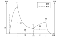
- FIG. 2 is a schematic diagram of current and temperature in spot welding in which the nugget is not cooled to the Mf point or below.
- FIG. 2 is a schematic diagram of current and temperature in spot welding in which the nugget is cooled to below the Mf point.
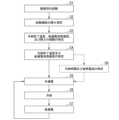
- FIG. 1 is a schematic diagram showing the correlation between the end temperature of cooling, the post-current heating rate, and the hardness of the test steel sheet after the post-current. 4 is a flowchart of a method for manufacturing a spot welded joint.
- FIG. 2 is a cross-sectional view of a spot welded joint.
- FIG. 1 is a schematic diagram of a thermal profile in a reproduced thermal cycle test.
- 1 is a graph showing a correlation between a cooling end temperature T2 in a reproduced heat cycle test and hardness of a steel sheet after the reproduced heat cycle test.
- 1 is a photograph of the metal structure of a nugget in a simulated thermal cycle test.
- 1 is a photograph of the metal structure of a nugget in a simulated thermal cycle test.
- 1 is a photograph of the metal structure of a nugget in a simulated thermal cycle test.
- 1 is a photograph of the metal structure of a nugget in a simulated thermal cycle test.
- 1 is a photograph of the metal structure of a nugget in a simulated thermal cycle test.
- FIG. 13 is a result of a simulation of the relationship between the cooling time and the cooling end temperature T2.
- FIG. 2 is a schematic diagram of a current flow pattern (a) employed in an experiment by the present inventors.
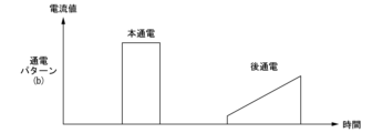
- FIG. 13 is a schematic diagram of a current flow pattern (b) employed in the inventors' experiments. The results are from a spot welding test. The results are from a spot welding test. The results are from a spot welding test. 13 shows simulation results of the weld temperature in the current flow pattern (a) and the current flow pattern (b).
- 4 shows a cross-sectional photograph and hardness measurement results of a spot-welded joint obtained by a spot welding test. 4 shows a cross-sectional photograph and hardness measurement results of a spot-welded joint obtained by a spot welding test.
- the inventors conducted extensive research to obtain a method for manufacturing a spot welded joint that allows for post-energization in a short time. As a result, they discovered that by appropriately shortening the cooling time (cooling time t2) that is performed after the main current, it is possible to manufacture a spot welded joint in a short time while ensuring the effect of post-energization. They also discovered that it is possible to identify an appropriate cooling time t2 by performing a test before spot welding. The technical concept of this disclosure is described below.
- the manufacturing method of a spot welded joint includes main current application, cooling, and post-current application.
- main current application a sheet assembly formed by overlapping a plurality of steel sheets 11 is sandwiched between the tips of electrodes for spot welding, and current and pressure are concentrated in a relatively small area to locally heat the sheet assembly, and pressure is applied by the electrodes at the same time.
- the current passed through the sheet assembly in the main current application is called the welding current.
- the main current application raises the temperature of the sheet assembly between the pair of electrodes to above the melting point.
- the current flow is stopped or the current value is reduced to a very low value while the plate assembly is still clamped between the tips of the electrodes.
- Spot welding electrodes have water cooling holes. With the electrodes in contact with the plate assembly, the resistance heat value is set to zero or close to zero, so that heat is transferred from the plate assembly to the electrodes. The temperature of the plate assembly between the pair of electrodes then drops rapidly. The molten metal formed by this current flow solidifies as it cools to form a nugget 12.
- the metal structure of the nugget 12 is austenite immediately after solidification of the nugget 12.
- the nugget 12 is rapidly cooled, which produces martensite in the nugget 12. This hardens the nugget 12.
- the temperature at which the austenite begins to transform into martensite during cooling is called the Ms point.
- the temperature at which the austenite has almost completely transformed into martensite during cooling is called the Mf point.
- the temperature of the nugget 12 is lowered to below the Mf point by cooling, and most of the metal structure of the nugget 12 becomes martensite.
- the post-current application current is passed through the plate assembly again to heat the nugget 12.
- the purpose of the post-current application is to temper the nugget 12, which has hardened due to cooling, and to soften the nugget 12. This increases the cross tensile strength of the weld.
- the current passed through the nugget 12 for the purpose of tempering is called the post-heat current.
- the martensite after the post-current treatment i.e., tempering heat treatment
- the martensite before the post-current treatment is called fresh martensite.
- the hardness of tempered martensite is lower than that of fresh martensite. Therefore, the hardness of the nugget 12 is reduced by the post-current treatment, and the cross tensile strength of the nugget 12 is improved.
- the amount of softening of the nugget 12 is an indicator of the effect of the post-current treatment.
- the reason for this lies in the temperature of the nugget 12 at the end of cooling (i.e., the start of post-current).
- the cooling time t2 is made sufficiently long to lower the temperature of the nugget below the Mf point before starting post-current (see Figure 2).
- the cooling time t2 is shortened, the temperature of the nugget 12 at the start of post-current will be above the Mf point (see Figure 1).
- post-current will start with austenite remaining in the nugget 12.
- the austenite remaining in the nugget 12 at the start of the post-current treatment becomes hard fresh martensite after the post-current treatment ends.
- the fresh martensite increases the hardness of the nugget 12.
- a reproduced heat cycle test reproduces the heat cycle that the heat-affected zone of the base material and the weld metal undergo when welding is performed, and examines changes in the base material characteristics and evaluates the phase transformation behavior (structure, mechanical performance) of the resulting weld metal. It is difficult to measure the temperature between the electrodes during spot welding.
- the reproduced heat cycle test makes it possible to accurately evaluate the relationship between the temperature at the start of post-current application and the hardness after the end of post-current application.
- the inventors conducted a simulated heat cycle test simulating the main current, cooling, and post-current of spot welding on a test steel plate simulating a plate assembly that is the base material of spot welding.
- the maximum heating temperature in the heating simulating the main current of spot welding, the cooling rate in the cooling simulating the cooling of spot welding, and the maximum heating temperature in the heating simulating post-current were all the same.
- the cooling time t2 in the cooling i.e., the cooling end temperature
- the heating rate in the heating simulating post-current post-current heating rate
- the cooling end temperature T2 is below (Ms + Mf)/2°C, it is possible to reduce the hardness of the test steel sheet. Therefore, it is possible to shorten the cooling time t2 while ensuring the softening amount of the nugget 12.
- the dashed line graph in Figure 3 shows the correlation between the cooling end temperature T2 and hardness when the post-current heating rate is high.
- the solid line graph in Figure 3 shows the correlation between the cooling end temperature T2 and hardness when the post-current heating rate is low.
- the cause of this phenomenon is presumed to be bainite transformation.
- the austenite becomes fresh martensite.
- the post-energization heating rate is small, part of the austenite transforms into bainite.
- the hardness of bainite is smaller than that of fresh martensite. Therefore, by reducing the post-energization heating rate, the amount of bainite in the nugget 12 can be increased and the amount of fresh martensite can be reduced. This reduces the hardness of the nugget 12.
- the cooling end temperature T2 can be increased and the cooling time t2 can be shortened.
- the time required for post-current (post-current time t3) becomes longer. If the post-current heating rate is set too small, the time required to manufacture the spot welded joint will actually become longer. Therefore, it is most desirable to adopt a post-current heating rate that can minimize the sum of the cooling time and the post-current time.
- a range of combinations of the cooling end temperature T2 and the post-energization heating rate that can ensure the joining strength required for the nugget 12 is specified in advance; (2) Identifying a combination of the cooling end temperature T2 and the post-current heating rate that can minimize the total value of the cooling time t2 and the post-current heating time t3 within the range; (3) After the temperature of the nugget 12 falls below the cooling end temperature T2, the post-current heating rate is applied and then the post-current is started promptly. This makes it possible to further shorten the time required to manufacture a spot welded joint while ensuring the joining strength of the nugget 12.
- the manufacturing method of the spot welded joint according to the present disclosure includes the steps of (S1) simulating the main current, cooling, and post-current of spot welding, and performing a reproduced heat cycle test on a test steel sheet multiple times with different end temperatures of cooling and different heating rates in the post-current, as shown in FIG.
- test simulating spot welding Prior to spot welding, a test simulating spot welding is conducted.
- the test subject is a test steel plate simulating a plate assembly, which is the base material for spot welding.
- the carbon content of the test steel plate is the same as the carbon content of the plate assembly. If the carbon content of the multiple steel plates 11 included in the plate assembly differs, the weighted average of the carbon content of the steel plates 11, weighted by the plate thickness of the steel plates 11, is considered to be the carbon content of the plate assembly.
- the carbon content is the element that has the greatest effect on the Ms point and Mf point.
- the test involves heating to simulate the main current flow of spot welding, cooling to simulate the cooling of spot welding, and heating to simulate the post-current flow of spot welding.
- the test is a replicated heat cycle test. In the replicated heat cycle test, the temperature of the test steel plate can be accurately measured and controlled.
- the test steel sheet In heating to simulate actual current flow for spot welding, the test steel sheet is heated. Note that, during actual current flow for spot welding, the steel sheet is heated above its melting point, but in heating to simulate actual current flow, it is not necessary to heat the test steel sheet to its melting point. It is sufficient to heat the test steel sheet to an extent that the structure of the test steel sheet is austenitized. For example, in heating to simulate actual current flow for spot welding, the inventors heated the test steel sheet to 900°C and held it for 5 minutes to austenitize the structure of the test steel sheet. Heating equivalent to this can be performed in heating to simulate actual current flow for spot welding.
- the temperature of the test steel plate is lowered.
- the cooling end temperature T2 is varied in multiple tests. This makes it possible to obtain data to identify the correlation between the cooling end temperature T2 and hardness.
- the cooling rate is the same in all tests.
- the cooling end temperature T2 is controlled via the cooling time t2.
- the test steel sheet is reheated.
- the reheating is performed up to the tempering temperature of the test steel sheet.
- the tempering temperature of the test steel sheet is, for example, 700°C.
- the heating rate is varied in multiple tests. This makes it possible to obtain data for identifying the correlation between the post-energization heating rate and hardness.
- the heating rate in the heating that simulates post-energization may also be referred to as the post-energization heating rate for convenience.
- the hardness measurement may be performed, for example, in accordance with JIS Z 2244:2009 "Vickers hardness test - Test method".
- the test force and other test conditions are the same for all hardness measurements.
- the specific test conditions are not particularly limited, and appropriate conditions can be selected according to the hardness of the test steel plate.
- the Vickers hardness measurement conditions for both ends 12E of the nugget 12 described later may be applied to the measurement of the hardness of the test steel plate.
- the dashed-dotted line graph illustrated in Figure 3 shows the correlation between the end cooling temperature T2 and the hardness of the test steel sheet when the post-current heating rate is high.
- the post-current heating rate is high, if the end cooling temperature T2 is X°C or lower, the hardness of the test steel sheet can be made equal to or lower than the target hardness.
- the solid-line graph illustrated in Figure 3 shows the correlation between the end cooling temperature T2 and the hardness of the test steel sheet when the post-current heating rate is low.
- the post-current heating rate is low, if the end cooling temperature T2 is Y°C or lower, the hardness of the test steel sheet can be made equal to or lower than the target hardness.
- increasing the post-energization heating rate can shorten the time required for post-energization, i.e., the post-energization time t3.
- increasing the post-energization heating rate lowers the upper limit of the cooling end temperature T2 at which the target hardness can be achieved. This lengthens the time required for cooling, i.e., the cooling time t2.
- spot welding is performed on the plate assembly. Spot welding involves main current, cooling, and post-current. As mentioned above, the carbon content of the plate assembly to be spot welded is the same as the carbon content of the test steel plate.
- a pair of electrodes for spot welding is used to pass a current through a sheet assembly, which is two or more stacked steel sheets 11. This causes the sheet assembly to melt between the pair of electrodes.
- the conditions for this current are not particularly limited. The conditions for this current can be appropriately selected to suit the sheet assembly. In general, conditions that ensure the diameter of the nugget and bring the amount of expulsion within an acceptable range are applied to the current.
- the current is reduced while the pair of electrodes is being pressed against the sheet assembly.
- the current is stopped and the current flowing through the electrodes is set to zero.
- the spot welding electrodes have water-cooling holes, and the tips of the electrodes are cooled by a coolant during spot welding. With the electrodes in contact with the sheet assembly, the resistance heat value is set to zero or a value close to zero, thereby cooling the molten metal and forming a nugget 12.
- the time when cooling ends is determined based on the combination of the cooling end temperature T2 and the post-current heating rate determined through the above-mentioned test. Cooling ends as soon as possible after the point when it is estimated that the temperature of the nugget 12 has fallen below the cooling end temperature T2 determined through the test.
- a pair of electrodes is used to post-energize the nugget 12 formed into a plate assembly by the main current and cooling.
- the post-current temperature T3, i.e., the maximum heating temperature in the post-current, is set to the tempering temperature of the nugget 12. This allows the nugget 12 to be tempered and its hardness to be reduced.
- the post-current temperature T3 is set to be the same as the maximum heating temperature in the heating simulating the post-current.
- the post-current heating rate is determined based on the combination of the cooling end temperature T2 and the post-current heating rate that minimizes the cooling time t2 and the post-current heating rate, as determined through the above-mentioned tests.
- the post-heating current in the post-current is controlled so that the post-current heating rate is equal to or lower than the post-current heating rate determined through the tests, and is as large as possible. It is not necessary to constantly control the post-current heating rate from the start to the end of the post-current. It is sufficient that the average heating rate during the post-current is below the upper limit value determined through the tests.
- the second actual current can be started immediately.
- the conditions obtained through testing are applicable to multiple spot welding.
- a test simulating spot welding is first performed. Then, a good combination of the cooling end temperature T2 and the post-energization heating rate is identified through the test.
- the combination allows the hardness of the nugget 12 to be equal to or lower than the target hardness. Furthermore, the combination allows both the cooling time t2 and the post-energization time t3 to be shortened.
- spot welding is performed to achieve a good combination of the cooling end temperature T2 and the post-energization heating rate determined through testing. This makes it possible to manufacture a spot welded joint having a nugget 12 that has been suitably tempered in a short period of time.
- the target value of the hardness of the test steel sheet used when specifying the combination of the cooling end temperature T2 and the post-energization heating rate is not particularly limited.
- the cross tensile strength required for the spot welded joint is determined according to, for example, the application, material, and shape of the spot welded joint.
- the target hardness can be appropriately selected according to the cross tensile strength required for the spot welded joint.
- the target value of hardness can be determined, for example, based on the estimated maximum Vickers hardness HVmax of the test steel sheet.
- the element symbols in the above formula are the contents of the elements corresponding to the element symbols in the chemical components of the test steel plate.
- the C, Mn, Cr, and Mo in the above formula are elements that improve the hardenability of the steel.
- the estimated maximum Vickers hardness HVmax calculated by the above formula is the estimated hardness of the steel when hardening is performed to maximize the hardness of the steel.
- the target hardness value may be set to a value equal to or less than "HVmax of the test steel plate - HV150", which further improves the joint strength (especially CTS).
- the carbon content of the test steel plate is approximately the same as the carbon content of the plate assembly to be spot-welded.
- the Mn content, Cr content, and Ni content of the test steel plate are also approximately the same as the Mn content, Cr content, and Ni content of the plate assembly to be spot-welded.
- the chemical composition of the test steel plate is the same as the chemical composition of the plate assembly to be spot-welded.
- the closer the Ms and Mf points of the test steel plate are to the Ms and Mf points of the plate assembly is closer to the Ms and Mf points of the plate assembly. This can further increase the reliability of the combination of the end temperature and heating rate identified through the test.
- the manufacturing method of a spot welded joint according to the present disclosure further includes a step S8 of estimating, by simulation, a cooling time and post-heating current that can reproduce the combination of the upper limit of the cooling end temperature and the lower limit of the heating rate determined by the reproduced thermal cycle test. In this case, it is preferable to apply the cooling time and post-current time identified by the simulation to the cooling and post-current of the plate assembly.
- the interelectrode resistance Another means for determining the time when the temperature of the nugget 12 is estimated to be below the cooling end temperature T2 determined by testing is the interelectrode resistance.
- the electrical resistance of steel is an indicator of the temperature of the steel. Therefore, the temperature of the nugget 12 can be estimated by measuring the current and voltage between the electrodes that clamp the plate assembly and calculating the interelectrode resistance. Note that in order to obtain the interelectrode resistance, a current must be passed through the electrodes. However, the current passed to obtain the interelectrode resistance does not interfere with cooling. This is because the current passed to obtain the interelectrode resistance can be extremely small.
- the post-heating current flowing during the post-current may be a constant value.
- the post-heating current may be up-slope controlled during at least a portion of the post-current.
- the up-slope control is a control for continuously increasing the current. It is particularly preferable to use up-slope current at least during the first half of the post-current, and more preferably to use up-slope current throughout the entire post-current. This increases the amount of bainite in the nugget 12, and further increases the amount of softening of the nugget 12.
- the type of steel plate 11 in the plate assembly is not particularly limited, but preferably, one or more of the steel plates 11 are high carbon steel plates.
- the high carbon steel plate is a steel plate 11 having a carbon content of 0.20 mass% or more. This allows the spot welded joint to be applied to mechanical parts that require high strength, such as automobile frame parts. It is known that the spot welded parts of high carbon steel plates are easily embrittled and their cross tensile strength is easily reduced.
- the nugget 12 can be softened in a short time to improve the cross tensile strength.
- the spot welded joint includes two or more overlapping steel plates 11 and a nugget 12 that joins the steel plates 11, and the metal structure of both ends 12E of the nugget 12 at a virtual line 13L along a joining interface 13 of the steel plates 11, as measured in a cross section of the nugget 12, contains 5 to 40 area % fresh martensite, and the remaining 95 area % or more is one or both of tempered martensite and bainite.
- the spot welded joint has two or more overlapping steel plates 11 and a nugget 12.
- the nugget 12 is a molten solidified portion that joins the steel plates 11.
- the configuration of the nugget 12 is defined by using a virtual line 13L along the joint interface 13.
- the joint interface 13 is a surface where the steel plates 11 contact and face each other.
- the joint interface 13 may also be called a mating surface.
- the joint interface 13 disappears inside the nugget 12.
- the virtual line 13L along the joint interface 13 is used to evaluate the nugget 12. When there are two steel plates 11, there is one joint interface 13 and one virtual line 13L. When there are three or more steel plates 11, there are two or more joint interfaces 13 and two or more virtual lines 13L.
- the end 12E of the nugget 12 at the virtual line 13L along the joint interface 13 refers to the area near the intersection of the outer edge of the nugget 12 (i.e., the fusion boundary) and the virtual line 13L, as shown in FIG. 5. There are two ends 12E at one virtual line 13L. When there are two or more virtual lines 13L, there are two ends 12E at each of the multiple virtual lines 13L.
- the end 12E of the nugget 12 at the imaginary line 13L along the joint interface 13 is an extremely important area for improving the joint strength of the nugget 12. This is because the end 12E along the joint interface 13 becomes a stress concentration area in a cross tensile test.
- the metal structure of each of the ends 12E of the nugget 12 includes 5 to 40 area % of fresh martensite.
- the region other than the fresh martensite is mainly composed of tempered martensite and/or bainite.
- 95 area % or more of the region other than the fresh martensite is one or both of tempered martensite and bainite. That is, the metal structure of both end portions 12E of the nugget 12 satisfies both of the following formulas.
- FM, TM, and B are the area fractions of fresh martensite, tempered martensite, and bainite, respectively, in the metal structure of both end portions 12E of the nugget 12.
- the area fraction FM of fresh martensite is a value obtained by dividing the area of fresh martensite in an observation field described below by the area of the observation field.
- the area fraction TM of tempered martensite is a value obtained by dividing the area of tempered martensite in an observation field by the area of the observation field
- the area fraction B of bainite is a value obtained by dividing the area of bainite in an observation field by the area of the observation field.
- Martensite is a metal structure that is produced when austenite is rapidly cooled and transformed without diffusion.
- Fresh martensite is martensite that has not been tempered.
- Tempered martensite is a tempered structure of martensite.
- the nugget 12 at the start of post-current is a mixture of martensite and austenite that has not been transformed into martensite.
- the martensite present at the start of post-current becomes tempered martensite after post-current.
- the austenite present at the start of post-current is transformed into bainite during post-current, or is transformed into martensite and becomes fresh martensite after post-current. Therefore, when cooling is stopped in a temperature range below the Ms point and above the Mf point before post-current is applied, the nugget 12 is a mixture of fresh martensite, tempered martensite, and/or bainite.
- the spot welded joint according to this embodiment can be manufactured by stopping cooling in a temperature range below the Ms point and above the Mf point before post-current is applied.
- the area ratio of fresh martensite may be 6% or more, 8% or more, 10% or more, 15% or more, or 18% or more. In the metal structure of both ends 12E of the nugget 12, the area ratio of fresh martensite may be 35% or less, 30% or less, 28% or less, 25% or less, or 20% or less. In the structure other than fresh martensite (remaining structure), the proportion of tempered martensite and bainite may be 96% or more, 98% or more, or 100%.
- the method for evaluating the fresh martensite content is as follows. First, the nugget 12 is cut. The cut surface is as close as possible to the center of the indentation 14 provided on the surface of the steel sheet 11. The cut surface is perpendicular to the surface of the steel sheet 11. The cut surface is then polished and etched with nital.
- the metal structure revealed by etching is observed using a SEM.
- the magnification of the SEM observation is 3000 times.
- the area ratio of the metal structure is measured in an observation field that satisfies the following requirements.
- the end portion 12E shown in FIG. 5 satisfies the following requirements.
- - Rectangular shape of 400 ⁇ m square - Center is on virtual line 13L along the joint interface 13 - One vertex coincides with the outer edge (melting boundary) of the nugget 12 - Two sides are parallel to virtual line 13L along the joint interface 13
- the area ratio of each structure at both ends 12E is measured and the average value is calculated.
- the number of steel plates 11 is three or more, the area ratio of the structure is measured at both ends for each of two or more joint interfaces 13 and the average value is calculated.
- the method for measuring the area ratio of the structure is as follows.
- Areas where the substructure is not revealed and has low brightness are considered to be ferrite. Areas that are lamellar structures of ferrite and cementite are considered to be pearlite. Areas where the substructure is not revealed and has high brightness are considered to be fresh martensite or retained austenite. Areas where the substructure is revealed are considered to be tempered martensite or bainite. When determining the total area fraction of tempered martensite and bainite in the remainder of the metal structure, i.e., in the areas other than fresh martensite in the metal structure, it is not necessary to distinguish between tempered martensite and bainite. A method for distinguishing between tempered martensite and bainite for the purpose of determining the area fraction of bainite is described below.
- the area fraction of fresh martensite is calculated by subtracting the volume fraction of retained austenite from the area fraction of the structure determined to be fresh martensite or retained austenite.
- the volume fraction of retained austenite is quantified from the (200) and (210) area fraction intensities of ferrite and the (200), (220), and (311) area fraction intensities of austenite using MoK ⁇ radiation. Note that although area fraction and volume fraction are different concepts, they can be considered to be essentially the same value. Therefore, when calculating the area fraction of fresh martensite, the volume fraction of retained austenite obtained by the above procedure is considered to be the area fraction.
- the metal structure of both ends 12E of the nugget 12 contains 5 area % or more of fresh martensite.
- Such a nugget 12 can be manufactured by stopping cooling in a temperature range of not more than the Ms point and not less than the Mf point, and then applying a current after that. Therefore, the spot welded joint according to this embodiment can be manufactured by spot welding with a shortened cooling time t2, and the manufacturing efficiency is high.
- the amount of fresh martensite in the metal structure of both ends 12E of the nugget 12 is 40 area % or less, and the remaining structure is mainly composed of tempered martensite and/or bainite. This increases the toughness of the nugget 12 and increases the cross tensile strength of the spot welded joint.
- the type of steel plate 11 in the spot welded joint is not particularly limited, but preferably, one or more of the steel plates 11 are high carbon steel plates.
- the high carbon steel plate is a steel plate 11 having a carbon content of 0.20 mass% or more. This allows the spot welded joint to be applied to mechanical parts that require high strength, such as automobile frame parts. It is known that the spot welds of high carbon steel plates are easily embrittled and their cross tensile strength is easily reduced.
- the nugget 12 can be softened in a short time to improve the cross tensile strength.
- the nugget 12 of the spot welded joint according to the present embodiment is preferably softer than the nugget 12 to which no post-energization is performed.
- the value obtained by subtracting the Vickers hardness of both end portions 12E of the nugget 12 from the estimated maximum Vickers hardness HVmax is HV50 or more.
- the estimated maximum Vickers hardness HVmax is a value calculated by the following formula.
- HVmax 217+1080 ⁇ (C+Si/70+Mn/113+Cr/93+Mo/30)
- the element symbols included in the above formula are the contents of the elements corresponding to the element symbols in the chemical components of the steel plate 11.
- the chemical components of the steel plate 11 are the weighted average of the chemical components of the steel plate 11, with the plate thickness being weighted.
- C, Mn, Cr, and Mo included in the above formula are elements that improve the hardenability of steel.
- the estimated maximum Vickers hardness HVmax calculated by the above formula is the estimated hardness of the steel when hardening is performed to maximize the hardness of the steel. Therefore, the estimated maximum Vickers hardness HVmax is an index of the hardness of the nugget 12 obtained by spot welding without post-current application.
- both ends 12E of the nugget 12 are sufficiently tempered. Therefore, the cross tensile strength of the spot welded joint is further increased.
- the chemical components of the steel plate 11 used to calculate the estimated maximum Vickers hardness may be measured by a general method. For example, a part of the steel plate 11 is cut to collect chips. The chemical components of the chips may then be measured using ICP-AES (Inductively Coupled Plasma-Atomic Emission Spectrometry) in accordance with JIS G 1201:2014.
- ICP-AES Inductively Coupled Plasma-Atomic Emission Spectrometry
- the C content which is difficult to measure using ICP-AES, may be measured using a combustion-infrared absorption method.
- the analytical sample is taken so as to obtain the average chemical composition throughout the thickness of the steel plate 11. Specifically, the analytical sample is taken from the t/4 position, avoiding the ends of the steel plate 11 in the width direction.
- the method for measuring the Vickers hardness of both ends 12E of the nugget 12 is as follows.
- the hardness of the nugget 12 is continuously measured on the imaginary line 13L along the joint interface 13 of the steel plates 11.
- the measurement interval is 100 ⁇ m.
- the test force is 200 gf.
- the minimum hardness value in the region within 400 ⁇ m from the end of the nugget 12 is regarded as the hardness of the end 12E of the nugget 12.
- the average value of the hardness at both ends 12E of the nugget 12 is calculated. If the number of steel plates 11 is three or more, the hardness is measured at both ends of each of the two or more joint interfaces 13, and the average value is calculated.
- the metal structure of both end portions 12E of the nugget 12 preferably contains bainite.
- the metal structure of both end portions of the nugget preferably contains 2 area % or more of bainite. More preferably, the metal structure of both end portions of the nugget contains 5 area % or more, 10 area % or more, or 15 area % or more of bainite.
- the area ratio B of bainite is the value obtained by dividing the area of bainite in the observation field by the area of the observation field.
- the hardness of bainite is less than that of fresh martensite. Therefore, by replacing fresh martensite with bainite, the hardness of the nugget 12 can be reduced. Furthermore, when manufacturing a nugget 12 with a large amount of bainite, the cooling time t2 can be shortened. In other words, a spot welded joint with an increased amount of bainite can be manufactured in an even shorter time.
- the upper limit of the amount of bainite is not particularly limited.
- the remaining amount of bainite may be 50 area % or less, 45 area % or less, or 40 area % or less.
- the method for measuring the amount of bainite in the metal structure of both ends 12E of the nugget 12 is as follows. First, the above-mentioned means is used to identify the areas in the observation field of both ends 12E of the nugget 12 where the substructure is revealed. The areas where the substructure is revealed are either tempered martensite or bainite. Therefore, by distinguishing between tempered martensite and bainite, the area ratio of bainite can be identified.
- the measurement interval is 0.2 ⁇ m.
- An EBSD analysis device is used for the measurement.
- the EBSD analysis device used by the inventors is composed of a thermal field emission scanning electron microscope (JEOL JSM-7200F) and an EBSD detector (EDAX Velocity (registered trademark) ultra-high speed EBSD detector).
- JEOL JSM-7200F thermal field emission scanning electron microscope
- EDAX Velocity registered trademark ultra-high speed EBSD detector.
- the area ratio of bainite can also be measured using an equivalent device to the above.
- the degree of vacuum in the device is 9.6 x 10⁻⁵ Pa or less
- the acceleration voltage is 25 kV
- the irradiation current level is 16.
- the obtained crystal orientation information is analyzed using version 7 or later of OIM Analysis (registered trademark) manufactured by EDAX/TSL solution. Measurement points between which the crystal orientation difference is 15° or more are regarded as grain boundaries. Areas surrounded by grain boundaries are regarded as crystal grains. The GAM value (Grain Average Misorientation value) of each of the multiple crystal grains is then measured. The GAM value is obtained by calculating the difference in crystal orientation between all measurement points present within a crystal grain. The average value of the crystal orientation differences is the GAM value of the crystal grain.
- the boundaries with a crystal orientation misorientation of more than 5° are displayed.
- the density of boundaries within the crystal grains with a crystal orientation misorientation of more than 5° i.e., the length of grain boundaries per unit area with a crystal orientation misorientation of more than 5°, is calculated.
- the density of boundaries with a crystal orientation misorientation of more than 5° is referred to as the 5° boundary density of the crystal grain.
- crystal grains having a GAM value of more than 0.5° and a 5° boundary density of 0.4 ⁇ m/ ⁇ m2 or less are regarded as bainite.
- the area ratio of crystal grains regarded as bainite By measuring the area ratio of crystal grains regarded as bainite, the area ratio of bainite contained in the remainder in the metal structure at both ends of the nugget can be calculated.
- the tensile strength of the steel plate 11 is not particularly limited. From the viewpoint of improving the rigidity and fracture resistance of the spot welded joint 1, it is preferable that at least one of the plurality of steel plates 11 is a high carbon steel plate having a tensile strength of 980 MPa or more. It is more preferable that the tensile strength of the high carbon steel plate is 1000 MPa or more, 1200 MPa or more, or 1500 MPa or more. On the other hand, at least one of the plurality of steel plates 11 may be a mild steel having a tensile strength of 500 MPa or less.
- the hardness of the steel plate 11 is not particularly limited. From the viewpoint of improving the rigidity and fracture resistance of the spot welded joint 1, it is preferable that at least one of the multiple steel plates 11 is a high carbon steel plate having a hardness of HV330 or more. It is even more preferable that the hardness of the high carbon steel plate is HV350 or more, HV400 or more, or HV450 or more. On the other hand, at least one of the multiple steel plates 11 may be mild steel.
- the thickness of the steel plates 11 is not particularly limited.
- the plate thickness ratio of the plate assembly is also not particularly limited.
- the plate thickness ratio of the plate assembly is the total plate thickness of the plate assembly divided by the thickness of the thinner of the steel plates 11 arranged on the surface of the plate assembly.
- the steel plates 11 are two thick high carbon steel plates and one thin mild steel plate.
- the high carbon steel plates are automobile frame members.
- the mild steel plates are automobile exterior members.
- the plate thickness of the high carbon steel plates is preferably 1.0 to 2.5 mm, for example.
- the plate thickness of the mild steel plates is preferably 0.4 to 1.2 mm, for example.
- the surface of the steel sheet 11 is plated.
- Types of plating include Al-based plating, Al-based alloy plating, Zn-based plating, and Zn-based alloy plating.
- the diameter of the nugget 12 is not particularly limited and can be appropriately selected within a range that does not cause poor joining.
- the diameter of the nugget 12 may be within a range of 2.5 ⁇ t to 5.0 ⁇ t.
- the diameter of the nugget 12 is 2.8 ⁇ t or more, 3.0 ⁇ t or more, or 3.2 ⁇ t or more.
- the diameter of the nugget 12 is 4.8 ⁇ t or less, 4.5 ⁇ t or less, or 4.2 ⁇ t or less.
- the diameter of the nugget 12 refers to the diameter of the nugget 12 measured at the joint interface 13 by a cross-sectional test of the welded portion.
- t refers to the average thickness of the two steel plates 11 that make up the joint interface 13 at which the diameter of the nugget 12 was measured.
- the diameter of the nugget 12 is within the above-mentioned range at one or more joint interfaces 13, and it is even more preferable that the diameter of the nugget 12 is within the above-mentioned range at all joint interfaces 13.
- the conditions in the example are merely one example of conditions adopted to confirm the feasibility and effects of the present disclosure.
- the present disclosure is not limited to this one example of conditions.
- Various conditions may be adopted in the present disclosure as long as they do not deviate from the gist of the present disclosure and the purpose of the present disclosure is achieved.
- Example 1 Reproduced heat cycle test
- the present inventors carried out a simulated heat cycle test simulating spot welding.
- the test steel sheets and the conditions of the simulated heat cycle test were as follows. ⁇ Steel type of test steel plate: 2 GPa-class hot stamping steel plate ⁇ Thickness of test steel plate: 2.0 mm Ms point of test steel plate: approx. 360°C Mf point of test steel plate: about 180°C - Thermal profile in the reproduced thermal cycle test: As shown in Figure 6
- the heating simulating the main current was performed under constant conditions.
- the maximum heating temperature was set as a constant condition.
- the cooling rate after the main current and the cooling rate after the post-current were also set as constant conditions.
- the cooling end temperature T2 i.e., the post-current temperature
- the post-current heating rate was set to either 400°C/sec or 100°C/sec.
- 8A to 8E show SEM photographs of the test steel sheets after the simulated thermal cycle test.
- the simulated thermal cycle test conditions for these test steel sheets were as follows: 8A: Cooling end temperature T2: room temperature, no post-current application; FIG. 8B: Cooling end temperature T2: 160° C., post-current application heating rate: 100° C./sec FIG. 8C: Cooling end temperature T2: 320° C., post-energization heating rate: 100° C./sec 8D: Cooling end temperature T2: 360° C., post-energization heating rate: 100° C./sec FIG. 8E: Cooling end temperature T2: room temperature, post-energization heating rate: 100° C./sec
- the cooling end temperature T2 was below the Mf point.
- the test steel plate in Figure 8B was sufficiently softened after the reproduced heat cycle test.
- the presence of precipitated carbides can be confirmed in the structural photograph in Figure 8B.
- the areas where carbides precipitate are tempered martensite or bainite.
- the cooling end temperature T2 was room temperature.
- the test steel plate in Figure 8E was sufficiently softened after the reproduced heat cycle test. The presence of precipitated carbides can be confirmed in the structural photograph in Figure 8E.
- Example 2 Four Masters Test
- the inventors conducted a Formaster test to examine the effect of the heating rate in reheating simulating post-energization on hardness.
- the thickness of the test steel sheet was measured while a reproduced heat cycle test simulating spot welding was performed on the test steel sheet.
- the steel sheet used in the Formaster test was the same as the test steel sheet in Experiment 1.
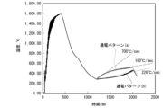
- the results of the Formaster test are shown in Figure 9.
- the horizontal axis of the graph shown in Figure 9 is temperature, and the vertical axis is the change in thickness of the steel sheet.
- the section marked with symbol (1) corresponds to heating simulating the main current flow of spot welding.
- the temperature of the test steel sheet was held at 900°C for 5 minutes.
- the section marked with symbol (2) corresponds to cooling simulating cooling of spot welding. Cooling was performed to 320°C.
- the section marked with symbol (3) corresponds to reheating simulating post-current flow. Reheating was performed to 700°C.
- the section marked with symbol (4) corresponds to cooling after post-current flow. Cooling after post-current flow was performed to room temperature.
- the thickness of the test steel plate increases in the sections marked with symbols (3) and (4). At the beginning of these sections, the thickness of the test steel plate increases or decreases monotonically. However, in the middle of these sections, the thickness of the test steel plate increases suddenly. The cause of this is presumed to be bainite transformation.
- Example 3 Estimation of cooling conditions using spot welding analysis software
- the relationship between the cooling time and the cooling end temperature T2 in spot welding of the test steel plate (a hot stamp steel plate having a thickness of 2.0 mm and a tensile strength of 2 GPa) used in Experiment 1 and Experiment 2 was simulated using spot welding analysis software SORPAS (registered trademark).
- SORPAS spot welding analysis software
- the simulation conditions for spot welding were as follows. Number of test steel plates: 2 Pressure: 3.92 kN ⁇ Main current application time: 0.36 seconds ⁇ Welding current during main current application: 8.0 kA ⁇ Nugget diameter: 7mm
- the simulation results are shown in FIG.
- the time required to raise the temperature of the test steel plate to 320°C is 50 cycles (1.0 second).
- the time required to raise the temperature of the test steel plate to 280°C is 55 cycles (1.1 seconds).
- the (D) post-energization time shown in Table 1 is a value calculated by the following formula.
- (D) 50 cycles/sec ⁇ ⁇ 700 ° C - (B) ⁇ / (A)
- “700°C” is the maximum temperature during post-current (see FIG. 6).
- “700°C-(B)” is the temperature rise required for post-current.
- "50 cycles/sec” in the above formula is the number of cycles per second.
- the cooling time can be shortened by reducing the temperature rise rate during post-current. However, reducing the temperature rise rate during post-current increases the post-current time. Therefore, it is not always preferable to reduce the post-current temperature rise rate. In the test steel plate used in this experiment, it was estimated that the welding time can be shortened by setting the temperature rise rate during post-current to 100°C/sec.
- Figure 12A shows the results of a spot welding test with a cooling time of (A) 40 cycles.
- Figure 12B shows the results of a spot welding test with a cooling time of (B) 50 cycles.
- Figure 12C shows the results of a spot welding test with a cooling time of (C) 60 cycles.
- Figure 13 shows the results of a simulation of the temperature of the weld in spot welding using current pattern (a) or current pattern (b). According to the simulation results, the amount of fluctuation in the heating rate is reduced by upslope control of the post-heating current. It is presumed that this promotes the formation of bainite.
- Figure 14 shows the cross-sectional observation results and hardness measurement results of the nugget with the maximum CTS in the spot welding test with a cooling time of 50 cycles and a post-current time of 55 cycles
- Figure 15 shows the cross-sectional observation results and hardness measurement results of the nugget with the maximum CTS in the spot welding test with a cooling time of 60 cycles and a post-current time of 55 cycles.
- the end of the nugget was sufficiently softened and the CTS was 10 kN or more.
- the CTS of the spot-welded joint manufactured without post-current was 6.5 kN. Therefore, it was confirmed that the effect of post-current was exerted under both post-current conditions.
- a reproduced heat cycle test was conducted to simulate the main current, cooling, and post-current of spot welding.
- a combination of the end temperature and heating rate was identified that would keep the hardness of the test steel sheet below the target value and minimize the total time required for cooling and post-current.
- cooling was terminated after the point at which the nugget temperature was estimated to have fallen below the end temperature identified by the reproduced heat cycle test.
- the heating rate in the post-current was set to be equal to or lower than the heating rate identified by the reproduced heat cycle test.
- Example 1 In the spot welding of Example 1, no post-current was applied. In the spot welded joint of Example 1, the nugget structure became entirely fresh martensite.
- Example 2 In the spot welding of Examples 2, 3, and 5, post-energization was performed. As a result, the amount of fresh martensite in the nuggets was reduced in the spot-welded joints of Examples 2, 3, and 5.
- the CTS of the spot-welded joints of Examples 2, 3, and 5 was significantly improved compared to Example 1. Furthermore, in the spot welding of Examples 2, 3, and 5, the cooling time and total value could be significantly reduced compared to Example 8.
- Example 4 post-current was applied.
- the total cooling time and post-current time in the spot welding of Example 4 were at the same level as in Example 3.
- the heating rate in the post-current was set to a value that exceeded the heating rate determined by the reproduced thermal cycle test.
- the amount of fresh martensite was not sufficiently reduced.
- the CTS of the spot-welded joint of Example 4 was only slightly improved compared to Example 1. In other words, in the spot welding of Example 4, the effect of post-current was hardly obtained.
Landscapes
- Engineering & Computer Science (AREA)
- Mechanical Engineering (AREA)
- Resistance Welding (AREA)
Priority Applications (1)
| Application Number | Priority Date | Filing Date | Title |
|---|---|---|---|
| JP2025557929A JP7828028B2 (ja) | 2023-11-17 | 2024-11-15 | スポット溶接継手、及びスポット溶接継手の製造方法 |
Applications Claiming Priority (2)
| Application Number | Priority Date | Filing Date | Title |
|---|---|---|---|
| JP2023-195627 | 2023-11-17 | ||
| JP2023195627 | 2023-11-17 |
Publications (1)
| Publication Number | Publication Date |
|---|---|
| WO2025105479A1 true WO2025105479A1 (ja) | 2025-05-22 |
Family
ID=95742776
Family Applications (1)
| Application Number | Title | Priority Date | Filing Date |
|---|---|---|---|
| PCT/JP2024/040670 Pending WO2025105479A1 (ja) | 2023-11-17 | 2024-11-15 | スポット溶接継手、及びスポット溶接継手の製造方法 |
Country Status (2)
| Country | Link |
|---|---|
| JP (1) | JP7828028B2 (https=) |
| WO (1) | WO2025105479A1 (https=) |
Citations (3)
| Publication number | Priority date | Publication date | Assignee | Title |
|---|---|---|---|---|
| US20080203139A1 (en) * | 2001-06-29 | 2008-08-28 | Mccrink Edward J | Method for controlling weld metal microstructure using localized controlled cooling of seam-welded joints |
| WO2011025015A1 (ja) * | 2009-08-31 | 2011-03-03 | 新日本製鐵株式会社 | スポット溶接継手およびスポット溶接方法 |
| JP2023108212A (ja) * | 2022-01-25 | 2023-08-04 | Jfeスチール株式会社 | 鋼帯の接合方法および鋼帯の接合装置 |
-
2024
- 2024-11-15 JP JP2025557929A patent/JP7828028B2/ja active Active
- 2024-11-15 WO PCT/JP2024/040670 patent/WO2025105479A1/ja active Pending
Patent Citations (3)
| Publication number | Priority date | Publication date | Assignee | Title |
|---|---|---|---|---|
| US20080203139A1 (en) * | 2001-06-29 | 2008-08-28 | Mccrink Edward J | Method for controlling weld metal microstructure using localized controlled cooling of seam-welded joints |
| WO2011025015A1 (ja) * | 2009-08-31 | 2011-03-03 | 新日本製鐵株式会社 | スポット溶接継手およびスポット溶接方法 |
| JP2023108212A (ja) * | 2022-01-25 | 2023-08-04 | Jfeスチール株式会社 | 鋼帯の接合方法および鋼帯の接合装置 |
Also Published As
| Publication number | Publication date |
|---|---|
| JP7828028B2 (ja) | 2026-03-11 |
| JPWO2025105479A1 (https=) | 2025-05-22 |
Similar Documents
| Publication | Publication Date | Title |
|---|---|---|
| US9475147B2 (en) | Method of resistance spot welding of high tensile strength steel sheet and welding joint manufactured by the method | |
| Laha et al. | Characterization of microstructures across the heat-affected zone of the modified 9Cr-1Mo weld joint to understand its role in promoting type IV cracking | |
| JP4865112B1 (ja) | 溶接継手の製造方法及び溶接継手 | |
| KR101725707B1 (ko) | 스폿 용접 방법 | |
| Kolhe et al. | Prediction of microstructure and mechanical properties of multipass SAW | |
| Aghajani et al. | Influence of in situ thermal processing strategies on the weldability of martensitic stainless steel resistance spot welds: effect of second pulse current on the weld microstructure and mechanical properties | |
| Hernandez et al. | Second pulse current in resistance spot welded TRIP steel—effects on the microstructure and mechanical behavior | |
| US10301692B2 (en) | Welding method and weld structure | |
| JP6313921B2 (ja) | 抵抗スポット溶接方法 | |
| Ashiri et al. | Weld processing and mechanical responses of 1-GPa TRIP steel resistance spot welds | |
| JP7633525B2 (ja) | スポット溶接継手の製造方法、及びスポット溶接装置 | |
| WO2013161937A1 (ja) | スポット溶接継手 | |
| WO2021177254A1 (ja) | 抵抗スポット溶接方法および抵抗スポット溶接継手の製造方法 | |
| Park et al. | Characterization of mechanical and metallurgical notch effects of DP980 steel weld joints in fatigue performance | |
| WO2022210749A1 (ja) | スポット溶接継手及びスポット溶接継手の製造方法 | |
| JP2002103054A (ja) | 高強度鋼板のスポット溶接方法 | |
| JP5171327B2 (ja) | 大入熱溶接熱影響部の板厚方向靭性に優れたスキンプレート用鋼板およびその製造方法 | |
| Dittrich et al. | HAZ characterization of welded 42SiCr steel treated by quenching and partitioning | |
| Ichiyama et al. | Flash-butt welding of high strength steels | |
| JP7828028B2 (ja) | スポット溶接継手、及びスポット溶接継手の製造方法 | |
| Taniguchi et al. | Examination of post-heating conditions to improve CTS in resistance spot-weld joints | |
| Görtan et al. | Control of the Martensitic Transformation During Resistance Spot Welding of High Strength S700MC Steel | |
| Yuhandri et al. | Effect of Heat Input on Microstructure and Mechanical Properties of Submerged Arc Welded SM570-TMC Steel | |
| Dewangan et al. | A Comparative Analysis among Quenched, Tempered, and Stepped Cooled TIG Welded SS‐304 Plates Based on Tensile Strength, Hardness, and Microstructural Appearance | |
| Han et al. | HAZ effects in hot-rolled dual-phase steel during flash butt welding of wheel rims |
Legal Events
| Date | Code | Title | Description |
|---|---|---|---|
| 121 | Ep: the epo has been informed by wipo that ep was designated in this application |
Ref document number: 24891514 Country of ref document: EP Kind code of ref document: A1 |
|
| ENP | Entry into the national phase |
Ref document number: 2025557929 Country of ref document: JP Kind code of ref document: A |
|
| WWE | Wipo information: entry into national phase |
Ref document number: 2025557929 Country of ref document: JP |