WO2025105166A1 - 金属接合体、羽根車、ポンプ、及び金属接合体の製造方法 - Google Patents
金属接合体、羽根車、ポンプ、及び金属接合体の製造方法 Download PDFInfo
- Publication number
- WO2025105166A1 WO2025105166A1 PCT/JP2024/038507 JP2024038507W WO2025105166A1 WO 2025105166 A1 WO2025105166 A1 WO 2025105166A1 JP 2024038507 W JP2024038507 W JP 2024038507W WO 2025105166 A1 WO2025105166 A1 WO 2025105166A1
- Authority
- WO
- WIPO (PCT)
- Prior art keywords
- metal plate
- metal
- joint
- plate
- impeller
- Prior art date
- Legal status (The legal status is an assumption and is not a legal conclusion. Google has not performed a legal analysis and makes no representation as to the accuracy of the status listed.)
- Pending
Links
Images



Classifications
-
- B—PERFORMING OPERATIONS; TRANSPORTING
- B23—MACHINE TOOLS; METAL-WORKING NOT OTHERWISE PROVIDED FOR
- B23K—SOLDERING OR UNSOLDERING; WELDING; CLADDING OR PLATING BY SOLDERING OR WELDING; CUTTING BY APPLYING HEAT LOCALLY, e.g. FLAME CUTTING; WORKING BY LASER BEAM
- B23K11/00—Resistance welding; Severing by resistance heating
- B23K11/14—Projection welding
-
- B—PERFORMING OPERATIONS; TRANSPORTING
- B23—MACHINE TOOLS; METAL-WORKING NOT OTHERWISE PROVIDED FOR
- B23K—SOLDERING OR UNSOLDERING; WELDING; CLADDING OR PLATING BY SOLDERING OR WELDING; CUTTING BY APPLYING HEAT LOCALLY, e.g. FLAME CUTTING; WORKING BY LASER BEAM
- B23K37/00—Auxiliary devices or processes, not specially adapted for a procedure covered by only one of the other main groups of this subclass
- B23K37/04—Auxiliary devices or processes, not specially adapted for a procedure covered by only one of the other main groups of this subclass for holding or positioning work
-
- F—MECHANICAL ENGINEERING; LIGHTING; HEATING; WEAPONS; BLASTING
- F04—POSITIVE - DISPLACEMENT MACHINES FOR LIQUIDS; PUMPS FOR LIQUIDS OR ELASTIC FLUIDS
- F04D—NON-POSITIVE-DISPLACEMENT PUMPS
- F04D29/00—Details, component parts, or accessories
- F04D29/18—Rotors
- F04D29/22—Rotors specially for centrifugal pumps
-
- F—MECHANICAL ENGINEERING; LIGHTING; HEATING; WEAPONS; BLASTING
- F04—POSITIVE - DISPLACEMENT MACHINES FOR LIQUIDS; PUMPS FOR LIQUIDS OR ELASTIC FLUIDS
- F04D—NON-POSITIVE-DISPLACEMENT PUMPS
- F04D29/00—Details, component parts, or accessories
- F04D29/18—Rotors
- F04D29/22—Rotors specially for centrifugal pumps
- F04D29/24—Vanes
-
- F—MECHANICAL ENGINEERING; LIGHTING; HEATING; WEAPONS; BLASTING
- F04—POSITIVE - DISPLACEMENT MACHINES FOR LIQUIDS; PUMPS FOR LIQUIDS OR ELASTIC FLUIDS
- F04D—NON-POSITIVE-DISPLACEMENT PUMPS
- F04D29/00—Details, component parts, or accessories
- F04D29/60—Mounting; Assembling; Disassembling
- F04D29/62—Mounting; Assembling; Disassembling of radial or helico-centrifugal pumps
Definitions
- the present invention relates to a metal joined body, an impeller, a pump, and a method for manufacturing the metal joined body.
- Patent Document 1 discloses an impeller used in a pump for pumping liquid.
- This impeller comprises a main plate having a through hole into which the pump shaft is inserted, multiple blades fixed to the main plate, and a side plate having a fluid inlet. The multiple blades are joined to the main plate and side plate by projection welding.
- T-shaped projection welding which is used in the manufacture of impellers and guide vanes, has the problem that the large joint that protrudes from the blade increases fluid resistance.
- the present invention was made in consideration of the above problems, and aims to provide a metal joint, an impeller, a pump, and a method for manufacturing a metal joint that can reduce fluid resistance.
- a metal joined body comprises a first metal plate, a second metal plate butted against the first metal plate in a T-shape, and a joint portion joining the first metal plate and the second metal plate, the joint portion comprising a first joint portion arranged on one side of the second metal plate, and a second joint portion arranged on the other side of the second metal plate and smaller than the first joint portion.
- the second joint portion may have a flat portion.
- the planar portion may include a first planar portion that is aligned with the first metal plate and a second planar portion that is aligned with the second metal plate.
- the angle between the first planar portion and the second planar portion may be a right angle.
- An impeller according to one aspect of the present invention comprises a metal joint body according to any one of (1) to (4), the first metal plate forms at least one of a main plate and a side plate, the second metal plate forms a plurality of blades joined to the main plate and the side plate, the second joint portion is disposed on the pressure side of the blade, and the first joint portion is disposed on the suction side of the blade.
- a pump according to one aspect of the present invention is provided with an impeller as described in (5).
- a method for manufacturing a metal joint body includes butting a second metal plate against a first metal plate in a T-shape and performing projection welding to form a first joint on one side of the second metal plate and to form a second joint, smaller than the first joint, on the other side of the second metal plate.
- the projection welding may be performed with a ceramic plate in contact with the other surface side of the second metal plate, and then the ceramic plate may be removed.
- a metal joint an impeller, a pump, and a method for manufacturing a metal joint that can reduce fluid resistance.
- FIG. 2 is a cross-sectional view of a metal bonded body according to an embodiment.
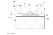
- FIG. 2 is a diagram showing a step of a method for producing a metal bonded body according to an embodiment.
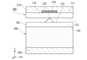
- FIG. 2 is a diagram showing a step of a method for producing a metal bonded body according to an embodiment.
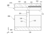
- FIG. 11 is a diagram showing one step of a method for manufacturing a metal bonded body according to a first modified example.
- FIG. 11 is a diagram showing one step of a method for manufacturing a metal bonded body according to a first modified example.
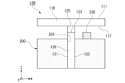
- FIG. 11 is a diagram showing one step of a method for manufacturing a metal bonded body according to a second modified example.
- FIG. 1 is a cross-sectional view of a metal bonded body according to an embodiment.
- FIG. 2 is a diagram showing a step of a method for producing a metal bonded body according to an embodiment.
- FIG. 2 is a diagram showing a step of a method for producing
- FIG. 11 is a diagram showing one step of a method for manufacturing a metal bonded body according to a second modified example.
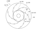
- FIG. 2 is a plan view of an impeller according to one embodiment.
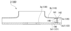
- FIG. 2 is a cross-sectional view of an impeller according to one embodiment.
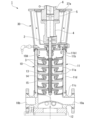
- FIG. 2 is a cross-sectional view of a pump according to an embodiment.
- FIG. 1 is a cross-sectional view of a metal bonded body 100 according to one embodiment.
- the metal joined body 100 includes a metal plate 110, a metal plate 120, and a metal plate 130.
- the metal plate 120 is joined to the metal plate 110 in a state where it is butted against the metal plate 110 in a T-shape.
- the metal plate 120 is joined to the metal plate 130 in a state where it is butted against the metal plate 130 in a T-shape.
- T-shaped includes not only a state in which the angle between metal plate 110 and metal plate 120 is a right angle (90°) as shown in FIG. 1, but also a state in which the angle is approximately a right angle.
- approximately a right angle refers to an angle in which a tilt of about 90° ⁇ 10° is permitted, for example.
- the angle between metal plate 120 and metal plate 130 may be not only a right angle, but also an approximately right angle.
- the X-axis direction is set to the thickness direction of the metal plate 120.
- the Y-axis direction and the Z-axis direction are set to the directions along the main surface (plate surface) of the metal plate 120.
- the "principal surfaces” refer to the set of surfaces with the largest area among the hexahedrons when metal plate 120 is considered to be a hexahedron surrounded by six rectangles. The same applies to metal plates 110 and 130.
- one side and the other side in the X-axis direction may be referred to as the -X side and the +X side
- one side and the other side in the Y-axis direction may be referred to as the -Y side and the +Y side
- one side and the other side in the Z-axis direction may be referred to as the -Z side and the +Z side.
- the metal plate 110 side (+Z side) of the metal plate 120 will be referred to as the upper side
- the metal plate 130 side (-Z side) of the metal plate 120 will be referred to as the lower side, but the Z-axis direction does not necessarily have to coincide with the direction of gravity.
- the metal plate 110 extends along the X-Y plane.
- the metal plate 110 has an upper surface 111 facing the +Z side and a lower surface 112 facing the -Z side.
- the upper surface 111 and the lower surface 112 are the main surfaces (plate surfaces) of the metal plate 110.
- the metal plate 120 extends along the Y-Z plane.
- the metal plate 120 has one surface 121 (left side surface) facing the -X side, and the other surface 122 (right side surface) facing the +X side.
- the one surface 121 and the other surface 122 are the main surfaces (plate surfaces) of the metal plate 120.
- the metal plate 130 extends along the X-Y plane.
- the metal plate 130 has an upper surface 131 facing the +Z side and a lower surface 132 facing the -Z side.
- the upper surface 131 and the lower surface 132 are the main surfaces (plate surfaces) of the metal plate 130.
- the upper end surface 123 of the metal plate 120 is joined to the lower surface 112 of the metal plate 110 by a joint 140.
- the lower end surface 124 of the metal plate 120 is joined to the lower surface 112 of the metal plate 110 by a joint 140.
- These joints 140 are welded metal formed by projection welding, which will be described later.
- First joint 141 bulges outward in a convex shape at each of the butt points between metal plate 110 and metal plate 120 and between metal plate 130 and metal plate 120.
- first joint 141 has a quadrant shape (a sector shape that is 1/4 of a circle) in the cross-sectional view shown in FIG. 1.
- first joint 141 is not limited to a quadrant shape, and may be, for example, a 1/4 shape of an ellipse, or a convex or concave parabolic shape.
- First joint 141 may also have a curved surface or uneven surface that cannot be defined by a circle, ellipse, or parabola.
- the second joint 142 is formed with an inward concave shape at each of the butt points of the metal plates 110 and 120 and at each of the butt points of the metal plates 130 and 120. Specifically, the second joint 142 has an L-shape in the cross-sectional view shown in FIG. 1.
- the second joint 142 shown in FIG. 1 includes a first flat surface portion 142a that runs along the metal plate 110 (or the metal plate 130) and a second flat surface portion 142b that runs along the metal plate 120.
- the first planar portion 142a is formed with a constant thickness along the lower surface 112 of the metal plate 110.
- the second planar portion 142b is formed with a constant thickness along the other surface 122 of the metal plate 110.
- the angle between the first planar portion 142a and the second planar portion 142b is a right angle, which is due to the manufacturing method of the metal joint body 100 described later.
- the angle between the first planar portion 142a and the second planar portion 142b formed at the butt point of the metal plate 110 and the metal plate 120 is approximately a right angle.
- the connection portion (corner portion) between the first planar portion 142a and the second planar portion 142b may include a curved surface.
- FIGS. 2A and 2B are diagrams showing a step in a method for manufacturing a metal joint 100 according to one embodiment. Specifically, FIGS. 2A and 2B show a state in which a metal plate 120 is butted against a metal plate 110 in a T-shape and projection-welded. Note that the direction in which the objects (metal plates 110, 120, etc.) are viewed is different between FIGS. 2A and 2B.
- the upper end surface 123 of the metal plate 120 is formed with a protrusion 125 (projection) that protrudes toward the +Z side.
- the metal plate 120 is fixed to a jig 200. As shown in FIG. 2A, the jig 200 has a storage groove 201 that stores the metal plate 120.
- the storage groove 201 stores a ceramic plate 300 together with the metal plate 120.
- the ceramic plate 300 extends along the Y-Z plane.
- the ceramic plate 300 has one surface 301 (left side surface) facing the -X side, and the other surface 302 (right side surface) facing the +X side.
- the one surface 301 and the other surface 302 are the main surfaces (plate surfaces) of the ceramic plate 300.
- the upper end surface 303 of the ceramic plate 300 is disposed so as to coincide with the upper end surface 123 of the metal plate 120. In other words, the position of the upper end surface 303 of the ceramic plate 300 and the upper end surface 123 of the metal plate 120 in the Z-axis direction is the same. As shown in FIG. 2B, the dimension of the ceramic plate 300 in the Y-axis direction (plate width direction) is larger than the dimension of the protrusion 125 in the Y-axis direction.
- Projection welding refers to resistance welding (spot welding) between metal plates 110 and 120 by pressing protrusion 125 of metal plate 120 against metal plate 110 in the state shown in Figures 2A and 2B, passing a large current through protrusion 125 from an electrode (not shown), and melting protrusion 125.
- the lower surface 112 of the metal plate 110 and the upper end surface 123 of the metal plate 120 approach each other in the Z-axis direction.
- the molten metal of the protrusion 125 extruded from between the lower surface 112 of the metal plate 110 and the upper end surface 123 of the metal plate 120 overflows onto one surface 121 and the other surface 122 of the metal plate 120, but since the ceramic plate 300 is disposed on the other surface 122 of the metal plate 120, most of the molten metal of the protrusion 125 overflows onto the one surface 121 of the metal plate 120.
- the remaining molten metal of the protrusion 125 also overflows onto the other surface 122 of the metal plate 120, but the molten metal penetrates into the gap between the lower surface 112 of the metal plate 110 and the upper end surface 123 of the ceramic plate 300, and into the gap between the other surface 122 of the metal plate 120 and one surface 301 of the ceramic plate 300.
- the metal plate 120 and the ceramic plate 300 are removed from the accommodation groove 201, and the ceramic plate 300 is removed. This forms the second joint 142 (the second joint 142 at the butt point of the metal plate 110 and the metal plate 120) having a flat portion as shown in FIG. 1.
- first joint 141 and the second joint 142 injection welding between the metal plates 110 and 120
- first joint 141 and the second joint 142 can be formed at the butt joint between the metal plates 130 and 120 (projection welding between the metal plates 130 and 120 can be performed).
- resin plate or a metal plate is used instead of the ceramic plate 300 in projection welding, the resin or metal will be welded to the metal plate 110 or the metal plate 120.
- the ceramic plate 300 is used in projection welding, the ceramic is not welded to the metal plate 110 or the metal plate 120, and therefore the ceramic plate 300 can be easily removed.
- a first joint 141 can be formed on one surface 121 of the metal plate 120, and a second joint 142, which is smaller than the first joint 141, can be formed on the other surface 122 of the metal plate 120.
- the first joint 141 and the second joint 142 which is smaller than the first joint 141, can also be formed by the following method.
- FIG. 3A and 3B are diagrams showing a step of a method for manufacturing a metal joined body 100 according to a first modified example. Note that, in Fig. 3A and Fig. 3B, electrodes 210 and 220 through which a current flows during projection welding are shown. The electrode 210 is disposed on the upper surface 111 side of the metal plate 110. The electrode 220 is disposed on the lower end surface 124 side of the metal plate 120.
- the insulating material 310 is disposed between the upper surface 111 of the metal plate 120 and the electrode 210 on the other surface 122 side of the metal plate 120.
- the current density during projection welding can be biased toward the one surface 121 side of the metal plate 120, and a large first joint portion 141 can be formed on the one surface 121 side of the metal plate 120, and a small second joint portion 142 can be formed on the other surface 122 side of the metal plate 120.
- the first joint 141 and the second joint 142 can be formed at the butt joint between the metal plates 130 and 120 (projection welding between the metal plates 130 and 120 can be performed).
- FIGS. 4A and 4B are diagrams showing a step of a method for producing a metal bonded body 100 according to a second modified example.
- a convex portion 330 is formed on a jig 200 instead of a ceramic plate 300 or an insulating material 310 .
- the protruding portion 330 is a part of the metal jig 200, and is disposed on the other surface 122 side of the metal plate 120. That is, the protruding portion 330 is disposed on the upper surface of the jig 200, and is located on the +X side of the other surface 122 of the metal plate 120. The protruding portion 330 protrudes on the +Z side toward the metal plate 110. According to this configuration, the current density during projection welding can be biased toward the one surface 121 side of the metal plate 120, and a large first joint portion 141 can be formed on the one surface 121 side of the metal plate 120, and a small second joint portion 142 can be formed on the other surface 122 side of the metal plate 120.
- first joint 141 and the second joint 142 injection welding between the metal plates 110 and 120
- first joint 141 and the second joint 142 can be formed at the butt joint between the metal plates 130 and 120 (projection welding between the metal plates 130 and 120 can be performed).
- Fig. 5 is a plan view of the impeller 3 according to one embodiment.
- Fig. 6 is a cross-sectional view of the impeller 3 according to one embodiment.
- the impeller 3 includes a main plate 3a, a side plate 3b, and a plurality of blades 3c.
- the main plate 3a is formed in a disk shape, and an insertion hole for inserting a rotating shaft (not shown) is formed in the center.
- the side plate 3b is formed in an annular shape coaxial with the main plate 3a, and is disposed with a gap in the axial direction from the main plate 3a.
- the main plate 3a and the side plate 3b are connected via a plurality of blades 3c.
- the space surrounded by the main plate 3a, the side plate 3b, and the plurality of blades 3c forms a flow path that guides the fluid radially outward.
- the side plate 3b forms the suction port of the impeller 3.
- the impeller 3 includes a metal joint 100 as shown in FIG. 1.
- the main plate 3a corresponds to the metal plate 130
- the side plate 3b corresponds to the metal plate 110
- the blade 3c corresponds to the metal plate 120.
- the second joint 142 is disposed on the pressure surface 3c2 side of the blade 3c
- the first joint 141 is disposed on the negative pressure surface 3c1 side of the blade 3c.
- the "positive pressure surface 3c2 of the blade 3c” refers to the surface facing the front side in the rotation direction of the impeller 3.
- the "negative pressure surface 3c1 of the blade 3c” refers to the surface facing the rear side in the rotation direction of the impeller 3.
- FIG. 7 is a cross-sectional view of the pump 1 according to one embodiment.
- the pump 1 shown in Fig. 7 is a vertical multi-stage pump including a rotating shaft 2 extending vertically and a plurality of impellers 3 fixed to the rotating shaft 2.
- the pump 1 includes a pump section 10, a motor section (not shown), and a coupling section 30.
- the coupling section 30 is disposed on the upper part of the pump section 10, and connects the rotating shaft 2 of the pump section 10 to the rotating shaft 6 of the motor section via couplings 4, 5.
- the couplings 4, 5 are covered from the outside by a guard member 37a.
- the pump section 10 includes a cylindrical casing 11 that houses the impeller 3.
- the casing 11 defines a pump chamber 10A inside, which pressurizes the liquid with the impeller 3.
- the casing 11 includes an intermediate casing 11a, an upper casing 11b disposed on the upper part of the intermediate casing 11a, a lower casing 11c disposed on the lower part of the intermediate casing 11a, and an outer casing 11d disposed radially outward of the intermediate casing 11a and the upper casing 11b.
- the upper casing 11b is formed in a cylindrical shape with a bottom like the intermediate casing 11a, and is stacked on top of the intermediate casing 11a.
- a number of communication holes 11b1 are formed in the peripheral wall of the upper casing 11b.
- the outer casing 11d is formed in a cylindrical shape that surrounds the radial outside of the intermediate casing 11a and the upper casing 11b.
- the outer casing 11d forms an annular flow path that communicates with the communication holes 11b1 on the radial outside of the intermediate casing 11a and the upper casing 11b.
- the lower casing 11c has an inlet 10a that communicates with the center of the bottom of the lowest intermediate casing 11a (the suction side of the impeller 3), and an outlet 10b that communicates with the annular flow passage inside the outer casing 11d.
- the inlet 10a and the outlet 10b are arranged back-to-back on the same line on the lower side of the pump section 10.
- the lower casing 11c supports the lower ends of the intermediate casing 11a and the outer casing 11d.
- a pump stand 12 is provided below the lower casing 11c.
- the pump stand 12 is axially connected to the coupling part 30 by a number of casing bolts and nuts (not shown).
- the multi-stage intermediate casing 11a, upper casing 11b, and lower casing 11c are clamped in the axial direction by fastening a number of casing bolts and nuts (not shown).
- the liquid is pressurized in multiple stages by the multiple impellers 3 and flows into the upper casing 11b.
- Multiple communication holes 11b1 are formed in the upper casing 11b, and the liquid in the upper casing 11b flows down from the communication holes 11b1 through an annular flow path formed on the outside of the upper casing 11b, and is discharged to the outside from the discharge port 10b of the lower casing 11c.
- the impeller 3 has a first joint 141 arranged on the negative pressure surface 3c1 side of the blade 3c, and a second joint 142 arranged on the positive pressure surface 3c2 side of the blade 3c and smaller than the first joint 141.
- the second joint 142 that protrudes onto the positive pressure surface 3c2 side of the blade 3c is small, so the flow resistance of the impeller 3 that guides liquid radially outward can be reduced.
- the second joint 142 has a flat surface, which makes it difficult for vortexes and stagnation of the liquid to occur, improving the performance of the pump 1.
- the metal joined body 100 includes metal plates 110, 130 (first metal plate), a metal plate 120 (second metal plate) butted against the metal plates 110, 130 in a T-shape, and a joint 140 that joins the metal plates 110, 130 and the metal plate 120, and the joint 140 includes a first joint 141 arranged on one surface 121 of the metal plate 120, and a second joint 142 arranged on the other surface 122 of the metal plate 120 and smaller than the first joint 141.
- This configuration can reduce the flow path resistance on the other surface 122 side of the metal plate 120.
- the second joint 142 has a flat portion.
- the planar portion includes a first planar portion 142a that is aligned with the metal plates 110 and 130, and a second planar portion 142b that is aligned with the metal plate 120.
- This configuration makes it possible to suppress the occurrence of vortexes and stagnation of the fluid on the surfaces of the metal plates 110 and 130 and the surface of the metal plate 120.
- the angle between the first flat portion 142a and the second flat portion 142b is a right angle.
- the impeller 3 includes the metal joint 100, in which the metal plates 110 and 130 form at least one of the main plate 3a and the side plate 3b, and the metal plate 120 forms a plurality of blades 3c joined to the main plate 3a and the side plate 3b, with the second joint 142 disposed on the positive pressure surface 3c2 side of the blades 3c and the first joint 141 disposed on the negative pressure surface 3c1 side of the blades 3c.
- This configuration allows the flow path resistance of the impeller 3 to be reduced.
- the pump 1 according to this embodiment also includes the impeller 3. This configuration improves the performance of the pump 1.
- the manufacturing method of the metal joint 100 involves butting the metal plate 120 against the metal plate 110 in a T-shape and performing projection welding, forming a first joint 141 on one surface 121 of the metal plate 120, and forming a second joint 142, smaller than the first joint 141, on the other surface 122 of the metal plate 120.
- projection welding is performed with the ceramic plate 300 in contact with the other surface 122 of the metal plate 120, and then the ceramic plate 300 is removed.
- This method makes it possible to manufacture a metal bonded body 100 that has a flat portion.
- the ceramic plate 300 is not welded to the metal plate 120 or the like during projection welding, and is therefore easy to remove.
- the impeller 3 including the metal joint 100 is applied to a vertical multi-stage pump, but it may be applied to other centrifugal pumps.
- the metal joint body 100 may be applied only between the main plate 3a and the blade 3c shown in FIG. 6, or only between the side plate 3b and the blade 3c.
- the metal joint body 100 may be applied not only to the impeller 3 but also to other fluid machines and fluid parts.
Landscapes
- Engineering & Computer Science (AREA)
- Mechanical Engineering (AREA)
- General Engineering & Computer Science (AREA)
- Physics & Mathematics (AREA)
- Optics & Photonics (AREA)
- Structures Of Non-Positive Displacement Pumps (AREA)
Abstract
金属接合体(100)は、金属板(110,130)(第1金属板)と、金属板(110,130)に対して、T字状に突き合わされた金属板(120)(第2金属板)と、金属板(110,130)と金属板(120)とを接合する接合部(140)と、を備え、接合部(140)は、金属板(120)の一方の面(121)側に配置された第1接合部(141)と、金属板(120)の他方の面(122)側に配置され、第1接合部(141)より小さい第2接合部(142)と、を備える。
Description
本発明は、金属接合体、羽根車、ポンプ、及び金属接合体の製造方法に関するものである。
本願は、2023年11月15日に、日本に出願された特願2023-194436号に基づき優先権を主張し、その内容をここに援用する。
本願は、2023年11月15日に、日本に出願された特願2023-194436号に基づき優先権を主張し、その内容をここに援用する。
下記特許文献1には、液体を圧送するためのポンプに使用される羽根車が開示されている。この羽根車は、ポンプの回転軸が挿入される貫通孔を有する主板と、主板に固定された複数の翼と、流体入口を有する側板と、を備えている。複数の翼は、主板及び側板に対してプロジェクション溶接により接合されている。
羽根車や、ガイドベーンの製造等に使用される、上記T字状のプロジェクション溶接では、翼からはみ出す接合部が大きいことで流体抵抗を増加させる、という問題がある。
本発明は、上記問題点に鑑みてなされたものであり、流体抵抗を減少させることができる金属接合体、羽根車、ポンプ、及び金属接合体の製造方法の提供を目的とする。
(1):本発明の一態様に係る金属接合体は、第1金属板と、前記第1金属板に対して、T字状に突き合わされた第2金属板と、前記第1金属板と前記第2金属板とを接合する接合部と、を備え、前記接合部は、前記第2金属板の一方の面側に配置された第1接合部と、前記第2金属板の他方の面側に配置され、前記第1接合部より小さい第2接合部と、を備える。
(2):(1)に係る金属接合体において、前記第2接合部は、平面部を備えてもよい。
(3):(2)に係る金属接合体において、前記平面部として、前記第1金属板に沿う第1平面部と、前記第2金属板に沿う第2平面部と、を備えてもよい。
(4):(3)に係る金属接合体において、前記第1平面部と前記第2平面部とがなす角度は、直角であってもよい。
(5):本発明の一態様に係る羽根車は、(1)~(4)のいずれか一つに記載の金属接合体を備え、前記第1金属板は、主板及び側板の少なくとも一方を形成し、前記第2金属板は、前記主板及び前記側板に接合された複数の翼を形成し、前記翼の正圧面側に、前記第2接合部が配置され、前記翼の負圧面側に、前記第1接合部が配置されている。
(6):本発明の一態様に係るポンプは、(5)に記載の羽根車を備える。
(7):本発明の一態様に係る金属接合体の製造方法は、第1金属板に対して、第2金属板をT字状に突き合わせてプロジェクション溶接を行い、前記第2金属板の一方の面側に第1接合部を形成すると共に、前記第2金属板の他方の面側に、前記第1接合部より小さい第2接合部を形成する。
(8):(7)に係る金属接合体の製造方法において、前記第2金属板の他方の面側にセラミックス板を当接させた状態で、前記プロジェクション溶接を行い、その後、前記セラミックス板を除去してもよい。
上記本発明の一態様によれば、流体抵抗を減少させることができる金属接合体、羽根車、ポンプ、及び金属接合体の製造方法を提供できる。
以下、本発明の一実施形態について図面を参照して説明する。
図1は、一実施形態に係る金属接合体100の断面構成図である。
図1に示すように、金属接合体100は、金属板110と、金属板120と、金属板130と、を備えている。金属板120は、金属板110に対してT字状に突き合わされた状態で、金属板110に対して接合されている。また、金属板120は、金属板130に対してT字状に突き合わされた状態で、金属板130に対して接合されている。
図1に示すように、金属接合体100は、金属板110と、金属板120と、金属板130と、を備えている。金属板120は、金属板110に対してT字状に突き合わされた状態で、金属板110に対して接合されている。また、金属板120は、金属板130に対してT字状に突き合わされた状態で、金属板130に対して接合されている。
なお、「T字状」とは、図1に示すように、金属板110と金属板120との角度が、直角(90°)である状態のみならず、略直角である状態を含む。「略直角」とは、例えば、90°±10°程度の傾きが許容される角度を言う。金属板120と金属板130との角度も同様に、直角のみならず略直角であってもよい。
以下の説明において、XYZ直交座標系を設定し、このXYZ直交座標系を参照しつつ各部材の位置関係について説明することがある。図1において、X軸方向は、金属板120の板厚方向に設定されている。また、Y軸方向及びZ軸方向は、金属板120の主面(板面)に沿う方向に設定されている。
なお、「主面」とは、金属板120を6つの四角形で囲まれた六面体と擬制したときに、当該六面体のうち最も面積の広い一組の面を言う。金属板110,130においても同様である。
以下の説明において、X軸方向における一方側及び他方側を-X側及び+X側と称し、Y軸方向における一方側及び他方側を-Y側及び+Y側と称し、Z軸方向における一方側及び他方側を-Z側及び+Z側と称する場合がある。
以下、説明の都合上、金属板120に対して金属板110側(+Z側)を上側と称し、金属板120に対して金属板130側(-Z側)を下側と称するが、必ずしもZ軸方向が重力方向に一致する必要はない。
以下、説明の都合上、金属板120に対して金属板110側(+Z側)を上側と称し、金属板120に対して金属板130側(-Z側)を下側と称するが、必ずしもZ軸方向が重力方向に一致する必要はない。
金属板110は、X-Y平面に沿って延在している。金属板110は、+Z側を向く上面111と、-Z側を向く下面112と、を有している。上面111及び下面112は、金属板110の主面(板面)である。
金属板120は、Y-Z平面に沿って延在している。金属板120は、-X側を向く一方の面121(左側面)と、+X側を向く他方の面122(右側面)と、を有している。一方の面121及び他方の面122は、金属板120の主面(板面)である。
金属板130は、X-Y平面に沿って延在している。金属板130は、+Z側を向く上面131と、-Z側を向く下面132と、を有している。上面131及び下面132は、金属板130の主面(板面)である。
金属板120の上端面123は、接合部140によって、金属板110の下面112に接合されている。また、金属板120の下端面124は、接合部140によって、金属板110の下面112に接合されている。これら接合部140は、後述するプロジェクション溶接により形成される溶接金属である。
接合部140は、金属板120の一方の面121側に配置された第1接合部141と、金属板120の他方の面122側に配置され、第1接合部141より小さい第2接合部142と、を備えている。なお、「第1接合部141より小さい」とは、図1に示す断面視において、第2接合部142の断面積が、第1接合部141の断面積より小さいことを言う。
第1接合部141は、金属板110と金属板120との突き合わせ箇所、及び金属板130と金属板120との突き合わせ箇所のそれぞれにおいて、外側に凸状に膨出している。具体的に、第1接合部141は、図1に示す断面視において、四分円形状(円の1/4の扇形形状)を有している。なお、第1接合部141は、四分円形状に限定されず、例えば、楕円の1/4の形状であってもよいし、凸状または凹状の放物線形状であってもよい。また、第1接合部141は、円、楕円、放物線で規定できない曲面や凹凸面を有してもよい。
第2接合部142は、金属板110と金属板120との突き合わせ箇所、及び金属板130と金属板120との突き合わせ箇所のそれぞれにおいて、内側に凹状に形成されている。具体的に、第2接合部142は、図1に示す断面視において、L字形状を有している。図1に示す第2接合部142は、金属板110(または金属板130)に沿う第1平面部142aと、金属板120に沿う第2平面部142bと、を備える。
第1平面部142aは、金属板110の下面112に沿って一定の厚みで形成されている。また、第2平面部142bは、金属板110の他方の面122に沿って一定の厚みで形成されている。第1平面部142aと第2平面部142bとがなす角度は、直角であるが、これは、後述する金属接合体100の製造方法に起因するものである。なお、金属板110と金属板120とがなす角度が略直角である場合、金属板110と金属板120との突き合わせ箇所に形成された第1平面部142aと第2平面部142bとがなす角度は略直角である。なお、第1平面部142aと第2平面部142bとの接続部(コーナー部)は、曲面を含んでもよい。
次に、上記構成の金属接合体100の製造方法について説明する。
図2A及び図2Bは、一実施形態に係る金属接合体100の製造方法の一工程を示す図である。具体的に、図2A及び図2Bは、金属板110に対して、金属板120をT字状に突き合わせてプロジェクション溶接する様子を示している。なお、図2Aと図2Bでは、対象物(金属板110,120等)を見る方向が異なっている。
金属板120の上端面123には、+Z側に突出する突起部125(プロジェクション)が形成されている。金属板120は、治具200に固定されている。治具200は、図2Aに示すように、金属板120を収容する収容溝201を備えている。収容溝201には、金属板120と共にセラミックス板300が収容されている。
セラミックス板300は、Y-Z平面に沿って延在している。セラミックス板300は、-X側を向く一方の面301(左側面)と、+X側を向く他方の面302(右側面)と、を有している。一方の面301及び他方の面302は、セラミックス板300の主面(板面)である。
セラミックス板300の一方の面301は、金属板120の他方の面122に当接している。また、セラミックス板300の上端面303は、金属板120の上端面123と一致するように設置されている。すなわち、セラミックス板300の上端面303と、金属板120の上端面123とのZ軸方向における位置は同じである。図2Bに示すように、セラミックス板300のY軸方向(板幅方向)の寸法は、突起部125のY軸方向の寸法よりも大きくなっている。
プロジェクション溶接(金属板110と金属板120とのプロジェクション溶接)とは、図2A及び図2Bに示す状態で、金属板120の突起部125を金属板110に押し付け、図示しない電極から突起部125に大電流を流し、突起部125を溶融させることで、金属板110と金属板120とを抵抗溶接(スポット溶接)することを言う。
突起部125が溶融すると、金属板110の下面112と、金属板120の上端面123とがZ軸方向で近接する。金属板110の下面112と金属板120の上端面123との間から押し出された突起部125の溶融金属は、金属板120の一方の面121側と他方の面122側にはみ出すが、金属板120の他方の面122側にはセラミックス板300が配置されているため、突起部125の溶融金属の大部分は、金属板120の一方の面121側にはみ出す。これにより、図1に示す第1接合部141(金属板110と金属板120との突き合わせ箇所における第1接合部141)が形成される。
また、突起部125の溶融金属の残部は、金属板120の他方の面122側にもはみ出すが、その溶融金属は、金属板110の下面112とセラミックス板300の上端面123との隙間、及び、金属板120の他方の面122とセラミックス板300の一方の面301との隙間などに入り込む。溶融金属が固まった後、収容溝201から金属板120及びセラミックス板300を取り出し、セラミックス板300を除去する。これにより、図1に示す、平面部を備える第2接合部142(金属板110と金属板120との突き合わせ箇所における第2接合部142)が形成される。
上記の例では、金属板110と金属板120との突き合わせ箇所における第1接合部141及び第2接合部142の形成方法(金属板110と金属板120とのプロジェクション溶接)について説明した。同様の方法によって、金属板130と金属板120との突き合わせ箇所において、第1接合部141及び第2接合部142を形成できる(金属板130と金属板120とのプロジェクション溶接を行うことができる)。
なお、プロジェクション溶接において、セラミックス板300の代わりに、樹脂板や金属板を用いる場合は、樹脂や金属が金属板110や金属板120に溶着してしまう。しかし、プロジェクション溶接においてセラミックス板300を用いる場合は、セラミックスが金属板110や金属板120に溶着しないため、セラミックス板300を、容易に除去することができる。
なお、プロジェクション溶接において、セラミックス板300の代わりに、樹脂板や金属板を用いる場合は、樹脂や金属が金属板110や金属板120に溶着してしまう。しかし、プロジェクション溶接においてセラミックス板300を用いる場合は、セラミックスが金属板110や金属板120に溶着しないため、セラミックス板300を、容易に除去することができる。
以上により、金属板120の一方の面121側に第1接合部141を形成すると共に、金属板120の他方の面122側に、第1接合部141より小さい第2接合部142を形成することができる。
なお、第1接合部141、及び、第1接合部141より小さい第2接合部142は、以下の方法によっても形成することができる。
図3A及び図3Bは、第1変形例に係る金属接合体100の製造方法の一工程を示す図である。なお、図3A及び図3Bでは、プロジェクション溶接する際に電流を流す電極210,220を図示している。
電極210は、金属板110の上面111側に配置されている。また、電極220は、金属板120の下端面124側に配置されている。
電極210は、金属板110の上面111側に配置されている。また、電極220は、金属板120の下端面124側に配置されている。
図3A及び図3Bに示す方法は、絶縁材料310を使用している。図3Aに示すように、絶縁材料310は、金属板120の他方の面122側において、金属板120の上面111と電極210との間に配置されている。この構成によれば、プロジェクション溶接の際の電流密度を、金属板120の一方の面121側に偏らせて、金属板120の一方の面121側に大きな第1接合部141を形成すると共に、金属板120の他方の面122側に小さな第2接合部142を形成することができる。
上記の例では、金属板110と金属板120との突き合わせ箇所における第1接合部141及び第2接合部142の形成方法(金属板110と金属板120とのプロジェクション溶接)について説明した。同様の方法によって、金属板130と金属板120との突き合わせ箇所において、第1接合部141及び第2接合部142を形成できる(金属板130と金属板120とのプロジェクション溶接を行うことができる)。
上記の例では、金属板110と金属板120との突き合わせ箇所における第1接合部141及び第2接合部142の形成方法(金属板110と金属板120とのプロジェクション溶接)について説明した。同様の方法によって、金属板130と金属板120との突き合わせ箇所において、第1接合部141及び第2接合部142を形成できる(金属板130と金属板120とのプロジェクション溶接を行うことができる)。
図4A及び図4Bは、第2変形例に係る金属接合体100の製造方法の一工程を示す図である。
図4A及び図4Bに示す方法は、セラミックス板300や絶縁材料310の代わりに、治具200に凸部330を形成している。
図4A及び図4Bに示す方法は、セラミックス板300や絶縁材料310の代わりに、治具200に凸部330を形成している。
凸部330は、金属製の治具200の一部であり、金属板120の他方の面122側に配置されている。すなわち、凸部330は、治具200の上面上に配置され、金属板120の他方の面122よりも+X側に位置している。凸部330は、金属板110に向かって+Z側に突出している。この構成によれば、プロジェクション溶接の際の電流密度を、金属板120の一方の面121側に偏らせて、金属板120の一方の面121側に大きな第1接合部141を形成すると共に、金属板120の他方の面122側に小さな第2接合部142を形成することができる。
上記の例では、金属板110と金属板120との突き合わせ箇所における第1接合部141及び第2接合部142の形成方法(金属板110と金属板120とのプロジェクション溶接)について説明した。同様の方法によって、金属板130と金属板120との突き合わせ箇所において、第1接合部141及び第2接合部142を形成できる(金属板130と金属板120とのプロジェクション溶接をすることができる)。
上記の例では、金属板110と金属板120との突き合わせ箇所における第1接合部141及び第2接合部142の形成方法(金属板110と金属板120とのプロジェクション溶接)について説明した。同様の方法によって、金属板130と金属板120との突き合わせ箇所において、第1接合部141及び第2接合部142を形成できる(金属板130と金属板120とのプロジェクション溶接をすることができる)。
次に、上記金属接合体100の適用例について説明する。
図5は、一実施形態に係る羽根車3の平面図である。図6は、一実施形態に係る羽根車3の断面図である。
これらの図に示すように、羽根車3は、主板3aと、側板3bと、複数の翼3cと、を備えている。主板3aは、円板状に形成され、その中心に図示しない回転軸を挿入する挿入孔が形成されている。側板3bは、主板3aと同軸の環状に形成され、主板3aと軸方向に隙間をあけて配置されている。主板3a及び側板3bは、複数の翼3cを介して接続されている。主板3a、側板3b、及び複数の翼3cによって囲まれた空間は、流体を径方向外側に導く流路となっている。側板3bは、羽根車3の吸込口を形成している。
これらの図に示すように、羽根車3は、主板3aと、側板3bと、複数の翼3cと、を備えている。主板3aは、円板状に形成され、その中心に図示しない回転軸を挿入する挿入孔が形成されている。側板3bは、主板3aと同軸の環状に形成され、主板3aと軸方向に隙間をあけて配置されている。主板3a及び側板3bは、複数の翼3cを介して接続されている。主板3a、側板3b、及び複数の翼3cによって囲まれた空間は、流体を径方向外側に導く流路となっている。側板3bは、羽根車3の吸込口を形成している。
羽根車3は、図1に示す金属接合体100を備えている。具体的に、主板3aは金属板130に相当し、側板3bは金属板110に相当し、翼3cは金属板120に相当するものである。図6に示すように、翼3cの正圧面3c2側に、第2接合部142が配置され、翼3cの負圧面3c1側に、第1接合部141が配置されている。なお、「翼3cの正圧面3c2」とは、羽根車3の回転方向前側を向く面である。また、「翼3cの負圧面3c1」とは、羽根車3の回転方向後側を向く面である。
図7は、一実施形態に係るポンプ1の断面構成図である。
図7に示すポンプ1は、鉛直方向に延びる回転軸2と、回転軸2に固定された複数の上記羽根車3と、を備える立形多段ポンプである。具体的に、ポンプ1は、ポンプ部10と、図示しないモータ部と、カップリング部30と、を備えている。カップリング部30は、ポンプ部10の上部に配置され、ポンプ部10の回転軸2と、モータ部の回転軸6とをカップリング4,5を介して接続している。なお、カップリング4,5は、ガード部材37aによって外側から覆われている。
図7に示すポンプ1は、鉛直方向に延びる回転軸2と、回転軸2に固定された複数の上記羽根車3と、を備える立形多段ポンプである。具体的に、ポンプ1は、ポンプ部10と、図示しないモータ部と、カップリング部30と、を備えている。カップリング部30は、ポンプ部10の上部に配置され、ポンプ部10の回転軸2と、モータ部の回転軸6とをカップリング4,5を介して接続している。なお、カップリング4,5は、ガード部材37aによって外側から覆われている。
ポンプ部10は、羽根車3を収容する筒状のケーシング11を備えている。ケーシング11は、羽根車3によって液体を昇圧するポンプ室10Aを内部に形成している。ケーシング11は、中間ケーシング11aと、中間ケーシング11aの上部に配置された上部ケーシング11bと、中間ケーシング11aの下部に配置された下部ケーシング11cと、中間ケーシング11a及び上部ケーシング11bの径方向外側に配置された外ケーシング11dと、を備える。
中間ケーシング11aは、鋼板などをプレス成形して有底筒状に形成され、その底部中央に回転軸2が挿通される開口が形成されている。中間ケーシング11aは、羽根車3の数に応じて多段に積み重ねられている。中間ケーシング11aの底部下面には、吸込板13が溶接により取り付けられている。また、吸込板13の下面には、戻し羽根14が溶接により取り付けられている。そして、中間ケーシング11aの底部開口の内壁には、羽根車3の吸込側への液体の漏れを防止するライナリング15が取り付けられている。
上部ケーシング11bは、中間ケーシング11aと同様の有底筒状に形成され、中間ケーシング11aの最上段に積み重ねられている。上部ケーシング11bの周壁には、複数の連通孔11b1が形成されている。外ケーシング11dは、中間ケーシング11a及び上部ケーシング11bの径方向外側を囲う円筒状に形成されている。外ケーシング11dは、中間ケーシング11a及び上部ケーシング11bの径方向外側に、連通孔11b1と連通する環状流路を形成している。
下部ケーシング11cは、最下段の中間ケーシング11aの底部中央(羽根車3の吸込側)に連通する吸込口10aと、外ケーシング11dの内側の上述した環状流路に連通する吐出口10bと、を有している。吸込口10a及び吐出口10bは、ポンプ部10の下部側面において背中合わせで同一直線上に配置されている。下部ケーシング11cは、中間ケーシング11a及び外ケーシング11dの下端部を支持している。
下部ケーシング11cの下部には、ポンプ台12が設けられている。ポンプ台12は、カップリング部30と、図示しない複数のケーシングボルト及びナットによって軸方向に連結されている。図示しない複数のケーシングボルト及びナットの締め付けにより、多段の中間ケーシング11a、上部ケーシング11b及び下部ケーシング11cは、軸方向において挟持されている。
上記構成のポンプ部10によれば、羽根車3が回転すると、吸込口10aから液体(流体)が下部ケーシング11c内に吸い込まれる。下部ケーシング11c内に吸い込まれた液体は、最下段の中間ケーシング11aにおいて1段目の羽根車3により昇圧される。1段目の羽根車3から吐き出された液体は、戻し羽根14及び吸込板13により形成される流路を通って次段の羽根車3の吸込側に導かれる。
このように、液体は複数の羽根車3により多段昇圧され、上部ケーシング11b内に流入する。上部ケーシング11bには複数の連通孔11b1が形成されており、上部ケーシング11b内の液体は、連通孔11b1から上部ケーシング11bの外側に形成された環状流路を通って下降し、下部ケーシング11cの吐出口10bから外部に吐出される。
ここで、羽根車3は、図5及び図6に示すように、翼3cの負圧面3c1側に配置された第1接合部141と、翼3cの正圧面3c2側に配置され、第1接合部141より小さい第2接合部142と、を備えている。この構成によれば、翼3cの正圧面3c2側に、はみ出す第2接合部142が小さいため、液体を径方向外側に導く羽根車3の流路抵抗を減少させることができる。また、第2接合部142は、平面部を備え、液体の渦や淀みなどができにくいため、ポンプ1の性能が向上する。
以上説明したように、本実施形態に係る金属接合体100は、金属板110,130(第1金属板)と、金属板110,130に対して、T字状に突き合わされた金属板120(第2金属板)と、金属板110,130と金属板120とを接合する接合部140と、を備え、接合部140は、金属板120の一方の面121側に配置された第1接合部141と、金属板120の他方の面122側に配置され、第1接合部141より小さい第2接合部142と、を備える。この構成によれば、金属板120の他方の面122側の流路抵抗を減少させることができる。
また、本実施形態では、第2接合部142は、平面部を備える。この構成によれば、本実施形態の金属接合体100を流体機械に適用した場合に、金属板120の他方の面122側に流体の渦や淀みなどができにくくなるため、流体機械の性能が向上する。
また、本実施形態では、平面部として、金属板110,130に沿う第1平面部142aと、金属板120に沿う第2平面部142bと、を備える。この構成によれば、金属板110,130の表面及び金属板120の表面における、流体の渦や淀みなどの発生を抑制できる。
また、本実施形態では、第1平面部142aと第2平面部142bとがなす角度は、直角である。この構成によれば、金属板120の他方の面122側に凸形状がなくなるため、流路抵抗をより減少させることができる。
また、本実施形態に係る羽根車3は、上記金属接合体100を備え、金属板110,130は、主板3a及び側板3bの少なくとも一方を形成し、金属板120は、主板3a及び側板3bに接合された複数の翼3cを形成し、翼3cの正圧面3c2側に、第2接合部142が配置され、翼3cの負圧面3c1側に、第1接合部141が配置されている。この構成によれば、羽根車3の流路抵抗を減少させることができる。
また、本実施形態に係るポンプ1は、上記羽根車3を備える。この構成によれば、ポンプ1の性能を向上させることができる。
また、本実施形態に係る金属接合体100の製造方法は、金属板110に対して、金属板120をT字状に突き合わせてプロジェクション溶接を行い、金属板120の一方の面121側に第1接合部141を形成すると共に、金属板120の他方の面122側に、第1接合部141より小さい第2接合部142を形成する。
また、本実施形態では、金属板120の他方の面122側にセラミックス板300を当接させた状態で、プロジェクション溶接を行い、その後、セラミックス板300を除去する。この手法によれば、平面部を備える金属接合体100を製造できる。また、セラミックス板300は、プロジェクション溶接において金属板120などに溶着しないため、除去が容易である。
このように、本実施形態によれば、流体抵抗を減少させることができる金属接合体100、羽根車3、ポンプ1、及び金属接合体100の製造方法を提供できる。
以上、本発明の好ましい実施形態を記載し説明してきたが、これらは本発明の例示的なものであり、限定するものとして考慮されるべきではないことを理解すべきである。追加、省略、置換、およびその他の変更は、本発明の範囲から逸脱することなく行うことができる。従って、本発明は、前述の説明によって限定されていると見なされるべきではなく、特許請求の範囲によって制限されている。
例えば、図7では、金属接合体100を備える羽根車3を、立形多段ポンプに適用したが、他の遠心ポンプに適用してもよい。
また、金属接合体100は、図6に示す主板3aと翼3cとの間のみに適用してもよいし、側板3bと翼3cとの間のみに適用してもよい。
また、金属接合体100は、羽根車3だけでなく、他の流体機械や流体部品に適用してもよい。
また、金属接合体100は、図6に示す主板3aと翼3cとの間のみに適用してもよいし、側板3bと翼3cとの間のみに適用してもよい。
また、金属接合体100は、羽根車3だけでなく、他の流体機械や流体部品に適用してもよい。
1 ポンプ
2 回転軸
3 羽根車
3a 主板
3b 側板
3c 翼
3c1 負圧面
3c2 正圧面
4 カップリング
5 カップリング
6 回転軸
10 ポンプ部
10a 吸込口
10A ポンプ室
10b 吐出口
11 ケーシング
11a 中間ケーシング
11b 上部ケーシング
11b1 連通孔
11c 下部ケーシング
11d 外ケーシング
12 ポンプ台
13 吸込板
14 羽根
15 ライナリング
30 カップリング部
37a ガード部材
100 金属接合体
110 金属板(第1金属板)
111 上面
112 下面
120 金属板(第2金属板)
121 一方の面
122 他方の面
123 上端面
124 下端面
125 突起部
130 金属板(第1金属板)
131 上面
132 下面
140 接合部
141 第1接合部
142 第2接合部
142a 第1平面部
142b 第2平面部
200 治具
201 収容溝
210 電極
220 電極
300 セラミックス板
301 一方の面
302 他方の面
303 上端面
310 絶縁材料
330 凸部
2 回転軸
3 羽根車
3a 主板
3b 側板
3c 翼
3c1 負圧面
3c2 正圧面
4 カップリング
5 カップリング
6 回転軸
10 ポンプ部
10a 吸込口
10A ポンプ室
10b 吐出口
11 ケーシング
11a 中間ケーシング
11b 上部ケーシング
11b1 連通孔
11c 下部ケーシング
11d 外ケーシング
12 ポンプ台
13 吸込板
14 羽根
15 ライナリング
30 カップリング部
37a ガード部材
100 金属接合体
110 金属板(第1金属板)
111 上面
112 下面
120 金属板(第2金属板)
121 一方の面
122 他方の面
123 上端面
124 下端面
125 突起部
130 金属板(第1金属板)
131 上面
132 下面
140 接合部
141 第1接合部
142 第2接合部
142a 第1平面部
142b 第2平面部
200 治具
201 収容溝
210 電極
220 電極
300 セラミックス板
301 一方の面
302 他方の面
303 上端面
310 絶縁材料
330 凸部
Claims (8)
- 第1金属板と、
前記第1金属板に対して、T字状に突き合わされた第2金属板と、
前記第1金属板と前記第2金属板とを接合する接合部と、を備え、
前記接合部は、
前記第2金属板の一方の面側に配置された第1接合部と、
前記第2金属板の他方の面側に配置され、前記第1接合部より小さい第2接合部と、を備える、
金属接合体。 - 前記第2接合部は、平面部を備える、
請求項1に記載の金属接合体。 - 前記平面部として、
前記第1金属板に沿う第1平面部と、
前記第2金属板に沿う第2平面部と、を備える、
請求項2に記載の金属接合体。 - 前記第1平面部と前記第2平面部とがなす角度は、直角である、
請求項3に記載の金属接合体。 - 請求項1~4のいずれか一項に記載の金属接合体を備え、
前記第1金属板は、主板及び側板の少なくとも一方を形成し、
前記第2金属板は、前記主板及び前記側板に接合された複数の翼を形成し、
前記翼の正圧面側に、前記第2接合部が配置され、
前記翼の負圧面側に、前記第1接合部が配置されている、
羽根車。 - 請求項5に記載の羽根車を備える、
ポンプ。 - 第1金属板に対して、第2金属板をT字状に突き合わせてプロジェクション溶接を行い、前記第2金属板の一方の面側に第1接合部を形成すると共に、前記第2金属板の他方の面側に、前記第1接合部より小さい第2接合部を形成する、
金属接合体の製造方法。 - 前記第2金属板の他方の面側にセラミックス板を当接させた状態で、前記プロジェクション溶接を行い、その後、前記セラミックス板を除去する、
請求項7に記載の金属接合体の製造方法。
Applications Claiming Priority (2)
| Application Number | Priority Date | Filing Date | Title |
|---|---|---|---|
| JP2023194436A JP2025080985A (ja) | 2023-11-15 | 2023-11-15 | 金属接合体、羽根車、ポンプ、及び金属接合体の製造方法 |
| JP2023-194436 | 2023-11-15 |
Publications (1)
| Publication Number | Publication Date |
|---|---|
| WO2025105166A1 true WO2025105166A1 (ja) | 2025-05-22 |
Family
ID=95742996
Family Applications (1)
| Application Number | Title | Priority Date | Filing Date |
|---|---|---|---|
| PCT/JP2024/038507 Pending WO2025105166A1 (ja) | 2023-11-15 | 2024-10-29 | 金属接合体、羽根車、ポンプ、及び金属接合体の製造方法 |
Country Status (2)
| Country | Link |
|---|---|
| JP (1) | JP2025080985A (ja) |
| WO (1) | WO2025105166A1 (ja) |
Citations (2)
| Publication number | Priority date | Publication date | Assignee | Title |
|---|---|---|---|---|
| JP2010229894A (ja) * | 2009-03-27 | 2010-10-14 | Hitachi Plant Technologies Ltd | 羽根車およびその製造方法 |
| JP2020084769A (ja) * | 2018-11-15 | 2020-06-04 | 株式会社荏原製作所 | 羽根車、該羽根車を備えたポンプ、および該羽根車の製造方法 |
-
2023
- 2023-11-15 JP JP2023194436A patent/JP2025080985A/ja active Pending
-
2024
- 2024-10-29 WO PCT/JP2024/038507 patent/WO2025105166A1/ja active Pending
Patent Citations (2)
| Publication number | Priority date | Publication date | Assignee | Title |
|---|---|---|---|---|
| JP2010229894A (ja) * | 2009-03-27 | 2010-10-14 | Hitachi Plant Technologies Ltd | 羽根車およびその製造方法 |
| JP2020084769A (ja) * | 2018-11-15 | 2020-06-04 | 株式会社荏原製作所 | 羽根車、該羽根車を備えたポンプ、および該羽根車の製造方法 |
Also Published As
| Publication number | Publication date |
|---|---|
| JP2025080985A (ja) | 2025-05-27 |
Similar Documents
| Publication | Publication Date | Title |
|---|---|---|
| US8899931B2 (en) | Impeller, compressor, and method for producing impeller | |
| JP5575202B2 (ja) | 磁気駆動ポンプ | |
| US9086075B2 (en) | Impeller assembly and method | |
| JPH02277998A (ja) | 羽根車 | |
| CN102203428B (zh) | 叶轮、压缩机及叶轮的制造方法 | |
| JP6982267B2 (ja) | クローズドインペラ及びクローズドインペラの製造方法 | |
| JP7213141B2 (ja) | 両吸込渦巻ポンプ | |
| JP5590081B2 (ja) | クロスフローファン | |
| JPH0718436B2 (ja) | 鋼板製中間ケーシング及び該中間ケーシングを用いた多段ポンプ | |
| EP3779206A1 (en) | Impeller with reinforced blades | |
| US11788543B2 (en) | Impeller, pump having the impeller, and method of producing the impeller | |
| WO2025105166A1 (ja) | 金属接合体、羽根車、ポンプ、及び金属接合体の製造方法 | |
| JP2004036444A (ja) | シュラウド付インペラーの製造方法 | |
| KR20170124029A (ko) | 임펠러 어셈블리 | |
| CN106246599A (zh) | 用于增压器的压缩机壳体及其制造方法 | |
| JP5664809B2 (ja) | クロスフローファン | |
| JP5633546B2 (ja) | 送風機 | |
| US12140150B2 (en) | Fluid pump impeller | |
| JP2020094550A (ja) | プロペラファン | |
| JP2005023794A (ja) | 羽根車 | |
| JP7636878B2 (ja) | ポンプ装置 | |
| JP2023004058A (ja) | インペラ及び水中ポンプ | |
| JPH0118278B2 (ja) | ||
| JP7670317B2 (ja) | インペラ、ポンプ装置及びインペラの製造方法 | |
| CN121356202A (zh) | 电动泵用转子 |
Legal Events
| Date | Code | Title | Description |
|---|---|---|---|
| 121 | Ep: the epo has been informed by wipo that ep was designated in this application |
Ref document number: 24891207 Country of ref document: EP Kind code of ref document: A1 |