WO2025100438A1 - Fe-Ni系合金薄板の製造方法およびFe-Ni系合金薄板 - Google Patents
Fe-Ni系合金薄板の製造方法およびFe-Ni系合金薄板 Download PDFInfo
- Publication number
- WO2025100438A1 WO2025100438A1 PCT/JP2024/039415 JP2024039415W WO2025100438A1 WO 2025100438 A1 WO2025100438 A1 WO 2025100438A1 JP 2024039415 W JP2024039415 W JP 2024039415W WO 2025100438 A1 WO2025100438 A1 WO 2025100438A1
- Authority
- WO
- WIPO (PCT)
- Prior art keywords
- thin plate
- less
- cold rolling
- alloy thin
- thin sheet
- Prior art date
- Legal status (The legal status is an assumption and is not a legal conclusion. Google has not performed a legal analysis and makes no representation as to the accuracy of the status listed.)
- Pending
Links
Classifications
-
- C—CHEMISTRY; METALLURGY
- C21—METALLURGY OF IRON
- C21D—MODIFYING THE PHYSICAL STRUCTURE OF FERROUS METALS; GENERAL DEVICES FOR HEAT TREATMENT OF FERROUS OR NON-FERROUS METALS OR ALLOYS; MAKING METAL MALLEABLE, e.g. BY DECARBURISATION OR TEMPERING
- C21D8/00—Modifying the physical properties of ferrous metals or ferrous alloys by deformation combined with, or followed by, heat treatment
- C21D8/02—Modifying the physical properties of ferrous metals or ferrous alloys by deformation combined with, or followed by, heat treatment during manufacturing of plates or strips
- C21D8/0221—Modifying the physical properties of ferrous metals or ferrous alloys by deformation combined with, or followed by, heat treatment during manufacturing of plates or strips characterised by the working steps
- C21D8/0236—Cold rolling
-
- C—CHEMISTRY; METALLURGY
- C21—METALLURGY OF IRON
- C21D—MODIFYING THE PHYSICAL STRUCTURE OF FERROUS METALS; GENERAL DEVICES FOR HEAT TREATMENT OF FERROUS OR NON-FERROUS METALS OR ALLOYS; MAKING METAL MALLEABLE, e.g. BY DECARBURISATION OR TEMPERING
- C21D8/00—Modifying the physical properties of ferrous metals or ferrous alloys by deformation combined with, or followed by, heat treatment
- C21D8/02—Modifying the physical properties of ferrous metals or ferrous alloys by deformation combined with, or followed by, heat treatment during manufacturing of plates or strips
- C21D8/0247—Modifying the physical properties of ferrous metals or ferrous alloys by deformation combined with, or followed by, heat treatment during manufacturing of plates or strips characterised by the heat treatment
- C21D8/0273—Final recrystallisation annealing
-
- C—CHEMISTRY; METALLURGY
- C21—METALLURGY OF IRON
- C21D—MODIFYING THE PHYSICAL STRUCTURE OF FERROUS METALS; GENERAL DEVICES FOR HEAT TREATMENT OF FERROUS OR NON-FERROUS METALS OR ALLOYS; MAKING METAL MALLEABLE, e.g. BY DECARBURISATION OR TEMPERING
- C21D9/00—Heat treatment, e.g. annealing, hardening, quenching or tempering, adapted for particular articles; Furnaces therefor
- C21D9/46—Heat treatment, e.g. annealing, hardening, quenching or tempering, adapted for particular articles; Furnaces therefor for sheet metals
-
- C—CHEMISTRY; METALLURGY
- C22—METALLURGY; FERROUS OR NON-FERROUS ALLOYS; TREATMENT OF ALLOYS OR NON-FERROUS METALS
- C22C—ALLOYS
- C22C19/00—Alloys based on nickel or cobalt
- C22C19/03—Alloys based on nickel or cobalt based on nickel
-
- C—CHEMISTRY; METALLURGY
- C22—METALLURGY; FERROUS OR NON-FERROUS ALLOYS; TREATMENT OF ALLOYS OR NON-FERROUS METALS
- C22C—ALLOYS
- C22C38/00—Ferrous alloys, e.g. steel alloys
-
- C—CHEMISTRY; METALLURGY
- C22—METALLURGY; FERROUS OR NON-FERROUS ALLOYS; TREATMENT OF ALLOYS OR NON-FERROUS METALS
- C22C—ALLOYS
- C22C38/00—Ferrous alloys, e.g. steel alloys
- C22C38/08—Ferrous alloys, e.g. steel alloys containing nickel
-
- C—CHEMISTRY; METALLURGY
- C22—METALLURGY; FERROUS OR NON-FERROUS ALLOYS; TREATMENT OF ALLOYS OR NON-FERROUS METALS
- C22F—CHANGING THE PHYSICAL STRUCTURE OF NON-FERROUS METALS AND NON-FERROUS ALLOYS
- C22F1/00—Changing the physical structure of non-ferrous metals or alloys by heat treatment or by hot or cold working
- C22F1/10—Changing the physical structure of non-ferrous metals or alloys by heat treatment or by hot or cold working of nickel or cobalt or alloys based thereon
-
- C—CHEMISTRY; METALLURGY
- C22—METALLURGY; FERROUS OR NON-FERROUS ALLOYS; TREATMENT OF ALLOYS OR NON-FERROUS METALS
- C22F—CHANGING THE PHYSICAL STRUCTURE OF NON-FERROUS METALS AND NON-FERROUS ALLOYS
- C22F1/00—Changing the physical structure of non-ferrous metals or alloys by heat treatment or by hot or cold working
Definitions
- the present invention relates to a method for producing thin Fe-Ni alloy sheets and thin Fe-Ni alloy sheets.
- Patent Document 1 discloses a method for manufacturing an Fe-Ni alloy containing 32 to 38 wt % of Ni by cold rolling, correcting the shape by applying a strain of 0.4 to 3%, and then performing strain relief annealing under conditions of a sheet temperature of 550 to 690° C. and a tension of 2 kgf/mm 2 or less, to produce an Fe-Ni low thermal expansion alloy thin plate having excellent sheet shape and thermal contraction resistance.
- Patent Document 2 discloses a method for producing a low thermal expansion alloy thin plate, in which a hot-rolled material is subjected to cold rolling and annealing at least once each, and the cold rolling rate before final recrystallization annealing is set to 90% or more, the annealing temperature of the final recrystallization annealing is set to 850° C. or more, and the final cold rolling rate is set to 30% or less, in order to improve the etching rate and etching accuracy of the Fe—Ni—Co-based low thermal expansion alloy thin plate.
- Patent Document 3 the applicant of the present application has proposed an Fe-Ni alloy thin plate having a thickness of 0.5 mm or less, which has a finish cold rolling process in which a cold rolling material is subjected to finish cold rolling at a rolling reduction rate of 5% to 50% to produce a thin plate, a final annealing process in which the thin plate after the finish cold rolling is annealed at a temperature of 800°C to 1000°C, and a tensile stress imparting process in which the thin plate after the final annealing process is subjected to shape correction under tension conditions of 200 to 400 MPa to impart tensile stress.
- the Fe-Ni thin plates that are the raw materials for these products are required to have a wide width, high flatness of the etched surface, and suppression of warping after etching.
- shape correction using a roller leveler or tension leveler has been effective in the past, but the residual stress imparted to the thin plate during shape correction is released during etching, causing warping, which becomes a problem.
- stress relief annealing is known, in which the thin plate is annealed at a temperature that does not reach the recrystallization temperature to remove the distortion.
- Patent Document 1 is an invention that can improve heat shrinkage resistance and flatness, but does not take into consideration the suppression of warping that occurs when half etching is performed on a wide thin plate, and there is still room for consideration.
- Patent Document 2 is an invention that can increase the (200) plane density of the rolled surface and improve etching accuracy, but there is no description of suppressing warping in processes after finish rolling, leaving room for further study on suppressing warping and improving flatness.
- Patent Document 3 is an excellent invention that can achieve both good flatness and excellent resistance to etching warpage.
- a metal mask since highly accurate pattern formation is required, half etching is performed on the material for the metal mask to various depths in the thickness direction.
- the deeper the etching the greater the concern about warpage due to the influence of residual stress. Therefore, there is a demand for a material that is less susceptible to deformation such as warpage even when half etching is performed to various depths.
- An object of the present invention is to provide a method for producing an Fe-Ni alloy thin plate having a thickness of 0.5 mm or less, which has better flatness and etching warpage resistance.
- One aspect of the present invention is a method for producing an Fe-Ni-based alloy thin plate, which includes a finish cold rolling process in which a cold rolling material containing, by mass%, C: ⁇ 0.01%, Si: ⁇ 0.5%, Mn: ⁇ 1.0%, Ni: 28 to 52%, with the balance being Fe and unavoidable impurities, is subjected to a finish cold rolling reduction of 5% to 50% to obtain a thin plate, a recrystallization annealing process in which the thin plate after the finish cold rolling is annealed at a temperature of 800° C.
- a tensile stress imparting process in which the thin plate after the recrystallization annealing process is subjected to shape correction under a tension of 200 to 600 MPa to impart tensile stress
- a strain relief annealing process in which strain relief annealing is performed at a temperature of 400° C. to 750° C. on the thin plate after the tensile stress imparting process, thereby obtaining an Fe-Ni-based alloy thin plate having a thickness of 0.5 mm or less.
- Another aspect of the present invention is an Fe-Ni based alloy thin plate having a thickness of 0.5 mm or less, containing, by mass%, C: ⁇ 0.01%, Si: ⁇ 0.5%, Mn: ⁇ 1.0%, Ni: 28-52%, with the balance being Fe and unavoidable impurities, wherein a sample having a length of 150 mm and a width of 30 mm is cut out from the Fe-Ni based alloy thin plate, the sample is etched from one side, and when 1 ⁇ 2 of the plate thickness of the sample is removed, the amount of warping is 10 mm or less, and the maximum floating height of the Fe-Ni based alloy thin plate over a length of 800 mm is 1.5 mm or less.
- the present invention provides an Fe-Ni alloy thin plate having a thickness of 0.5 mm or less that is capable of achieving both good flatness and etching warpage resistance.
- the invention proposed by the applicant of the present application and shown in Patent Document 3 is capable of achieving both good flatness and excellent resistance to etching warpage, and based on this, the present applicant has found optimal manufacturing conditions that can achieve both good flatness and excellent resistance to etching warpage.
- the manufacturing method of the Fe-Ni alloy thin plate of the present invention is explained below.
- a hot-rolled material is prepared having a composition containing, by mass%, C: ⁇ 0.01%, Si: ⁇ 0.5%, Mn: ⁇ 1.0%, Ni: 28-52%, and the balance being Fe and unavoidable impurities.
- the hot-rolled material of the Fe-Ni alloy thin plate having the composition specified in the present invention has a composition necessary to obtain a desired thermal expansion coefficient.
- the reasons for specifying the above-mentioned composition range are as follows. [C: ⁇ 0.01% by mass] C is an element that affects etching properties. If C is contained in an excessive amount, it inhibits etching properties, so the upper limit of C is set to 0.01%. The lower limit may be 0%, but since C is contained in no small amount in the manufacturing process, there is no particular limitation.
- Si and Mn are usually used for the purpose of deoxidization, and are contained in Fe-Ni alloys in trace amounts, but if contained in excess, they are likely to cause segregation, so the Si content is set to 0.5% or less and the Mn content to 1.0% or less.
- the preferred Si and Mn contents are 0.1% or less and 0.5% or less.
- Ni is an element that adjusts the thermal expansion coefficient and has a large effect on low thermal expansion properties.
- the content is less than 28% or more than 52%, the effect of reducing the thermal expansion coefficient is lost, so the Ni range is 28-52%.
- the preferred lower limit of the Ni content is 30%, the more preferred lower limit of the Ni content is 32%, and the even more preferred lower limit of the Ni content is 34%.
- the preferred upper limit of the Ni content is 50%, the more preferred upper limit of the Ni content is 45%, and the even more preferred upper limit of the Ni content is 38%.
- the rest of the above is Fe and unavoidable impurities.
- a part of Ni can be replaced with Co.
- a strip-shaped cold rolling material having the above-mentioned composition is prepared.
- This cold rolling material can be obtained, for example, by mechanically or chemically removing an oxide layer from a hot rolled material having the above-mentioned composition.
- the edges of the cold rolled material may be trimmed to prevent defects such as cracks from occurring at the edges during cold rolling. If necessary, a homogenization heat treatment may be performed at about 1200°C before cold rolling.
- intermediate cold rollings may be performed to adjust the plate thickness before the finish cold rolling described later.
- intermediate cold rolling may be omitted.
- intermediate annealing may be performed on the thin plate after intermediate cold rolling to soften the work-hardened material and remove processing strain.
- the temperature of this intermediate annealing may be set to a temperature of 800 ° C or more at which recrystallization is promoted. If the temperature during annealing is less than 800 ° C, the material may not be sufficiently softened and the desired characteristics may not be obtained.
- the upper limit of the annealing temperature is not particularly limited, but if the temperature is raised too much, it is highly likely that the desired characteristics will not be obtained, so it can be set to about 1100 ° C.
- the heating retention time at this time may be appropriately adjusted according to the composition and plate thickness of the material.
- this intermediate annealing can be performed by continuously passing the thin plate after intermediate cold rolling through a heating furnace set to the desired temperature. For example, the sheet after intermediate cold rolling may be pulled out from the rolled state, passed through a heating furnace, and wound into a roll.
- the intermediate material after the intermediate cold rolling or intermediate annealing is subjected to a finish cold rolling with a rolling reduction of 5% to 50% to obtain a thin plate.
- a rolling reduction within the range of the above-mentioned rolling reduction, the difference in elongation between the center and end of the intermediate material is reduced, thereby suppressing the occurrence of excessively corrugated shapes, and it is possible to easily adjust the shape to a flat shape after the shape correction process described below.
- the rolling reduction is less than 5%, intermediate elongation occurs, and the flatness of the center of the thin plate after shape correction tends to decrease.
- the rolling reduction when the rolling reduction is less than 5%, the recrystallization of the thin plate tends to be excessively promoted in the recrystallization heat treatment described below, and the hardness of the thin plate tends to decrease.
- the rolling reduction is more than 50%, the end waves become stronger, and the flatness tends to decrease after shape correction.
- the preferable lower limit of the rolling reduction is 15%, and the more preferable lower limit of the rolling reduction is 20%.
- the preferable upper limit of the rolling reduction is 40%, and the more preferable upper limit of the rolling reduction is 30%.
- the number of passes of the finish cold rolling is preferably one pass.
- the manufacturing method of this embodiment can be applied to thin plates having a width of 300 to 1100 mm.
- a recrystallization annealing process is performed on a thin plate (finish cold-rolled thin plate) that has been subjected to finish cold rolling, in which annealing is performed at a temperature of 800°C to 1000°C.
- This process sufficiently reduces the yield strength of the plate while removing the processing strain caused by rolling, making it easier to improve the flatness in the tensile stress application process described later.
- the temperature during recrystallization annealing is less than 800°C, the processing strain cannot be sufficiently removed, and if the temperature is more than 1000°C, the hardness of the thin plate tends to decrease too much, which is not preferable.
- the lower limit of the preferred recrystallization annealing temperature is 850°C
- the upper limit of the preferred recrystallization annealing temperature is 950°C.
- the preferable lower limit of the tension is 250 MPa
- the preferable upper limit of the tension is 500 MPa
- the more preferable upper limit of the tension is 450 MPa
- the even more preferable upper limit of the tension is 400 MPa.
- a stress relief annealing process is performed on the thin plate (shape-corrected thin plate) after the tensile stress imparting process, in which annealing is performed at a temperature of 400°C to 750°C, to obtain the Fe-Ni alloy thin plate of the present invention.
- this "strain relief annealing process" which is not disclosed in Patent Document 3 is essential.
- the tensile stress imparting process of the present invention is a process that imparts bending stress to the plate as little as possible, but since the stress difference between the plate surface layer and the plate thickness center portion still remains, there is a risk that the above-mentioned residual stress will be released when deep etching is performed, and excessive warping will occur.
- the above-mentioned stress relief annealing process by performing the above-mentioned stress relief annealing process, it is possible to obtain an Fe-Ni alloy thin plate that can eliminate the residual stress difference of the plate generated by the tensile stress imparting process and suppress the warping caused by etching while having excellent flatness.
- the lower limit of the preferable stress relief annealing temperature is 500°C
- the upper limit of the preferable stress relief annealing temperature is 700°C.
- the thin plate for Fe-Ni alloy of this embodiment is characterized in that when cut into a sample size of 150 mm in the length direction (rolling direction) and 30 mm in the width direction (direction perpendicular to rolling), the amount of warping when 1/2 of the plate thickness of the sample is removed is 10 mm or less.
- the thin plate of this embodiment has reduced residual stress at the center of the plate thickness, and even if etching is performed to the depth of the center of the plate thickness where the balance of stress is more disturbed, it is possible to suppress deformation of the plate material, and it is possible to ensure shape accuracy while proceeding with etching processing well.
- the amount of warping when 1/2 of the plate thickness is removed is 10 mm or less, which is more likely to be affected by warping than when 1/3 of the plate thickness is removed as described in Patent Document 3, it can be considered that the residual strain at the complex shape and deep cross-sectional position is also released, and it is suitable as a material for performing various etching.
- a more preferable upper limit of the amount of warping is 7 mm, and an even more preferable upper limit of the amount of warping is 5 mm.
- the sample is cut so that the longitudinal direction is the rolling direction to prepare a cut sample with a length of 150 mm and a width of 30 mm, and 1/2 of the plate thickness is removed from one side by etching.
- one end (upper end) of the cut sample in the longitudinal direction is hung in contact with a vertical platen, and the horizontal distance between the other end (lower end) of the cut sample that is separated from the vertical platen due to warping and the vertical platen is measured as the amount of warping.
- the case where the etched surface warps to the concave side is considered to be a "+" warp
- the case where the etched surface warps to the convex side is considered to be a "-" warp.
- the amount of warping is evaluated as an absolute value, and the smaller the absolute value, the more preferable it is.
- the amount of warping when 1/2 of the plate thickness of the sample is removed is 10 mm or less (more preferably 7 mm or less, and even more preferably 5 mm or less).
- the Fe-Ni alloy thin plate of this embodiment can also have a lower maximum floating height at a length of 800 mm than conventional products. Specifically, the maximum floating height is 1.5 mm or less when the length of the Fe-Ni alloy thin plate is 800 mm.
- the thin plate obtained by carrying out the manufacturing method of the present invention described above has excellent flatness even in a wide thin plate material having a width of 800 mm or more (preferably 900 mm or more, more preferably 1000 mm or more), and tends to exhibit effects such as improved dimensional accuracy in etching processing.
- a more preferable maximum floating height value is 1.2 mm or less, and a further more preferable maximum floating height value is 1.0 mm or less.
- the lower limit of the maximum floating height may be set to, for example, about 0.1 mm.
- the floating height can be measured by cutting the thin plate to a length of 800 mm, placing it on a horizontal platen, and measuring the floating height of the thin plate using a laser displacement meter or the like.
- the Fe-Ni alloy thin plate of the present embodiment preferably has a maximum steepness of 0.7% or less at a length of 800 mm.
- the Fe-Ni alloy thin plate of the present invention that satisfies this provision has a better flatness.
- a more preferable value of the maximum steepness is 0.5% or less, and an even more preferable value of the maximum steepness is 0.3% or less.
- the lower limit of the maximum steepness is not particularly limited, but since it is extremely difficult to manufacture a completely flat shape, as with the floating height, the lower limit of the maximum steepness may be, for example, about 0.01%.
- the steepness can be measured by calculating the steepness from data in which the floating height is recorded in a matrix form at every fixed length in the plate width and plate length directions.
- the Fe-Ni alloy thin plate of this embodiment preferably has a tensile strength of 400 MPa or more and a 0.2% proof stress of 200 MPa or more.
- the elongation may be set to 20 to 50%. This allows the Fe-Ni alloy thin plate of this embodiment to exhibit excellent flatness and etching warpage resistance as well as excellent plastic workability, and tends to be less susceptible to breakage or cracks during winding or plastic working.
- the preferred lower limit of the tensile strength is 450 MPa, and the preferred lower limit of the 0.2% proof stress is 250 MPa.
- the preferred lower limit of the elongation is 25%, and the preferred upper limit of the elongation is 45%.
- the tensile strength, 0.2% proof stress, and elongation properties can be determined by tests based on the methods specified in JIS-Z2241.
- An Fe-Ni alloy having the composition shown in Table 1 was hot pressed and hot rolled to prepare a hot rolled material having a thickness of 3.0 mm.
- the hot rolled material was chemically polished and mechanically polished to remove the oxide layer on the surface of the hot rolled material, and then the hot rolling cracks at both ends in the material width direction were removed by trimming.
- the material was then divided into an example of the present invention and a comparative example, and each was subjected to intermediate cold rolling and intermediate annealing (approximately 900°C) to produce intermediate cold rolled material having a width of 1040 mm and a thickness of 0.2 mm.
- both the example of the present invention and the comparative example were subjected to one pass of finish cold rolling at a rolling reduction rate of 25% to form a thin plate shape (finish cold rolled thin plate).
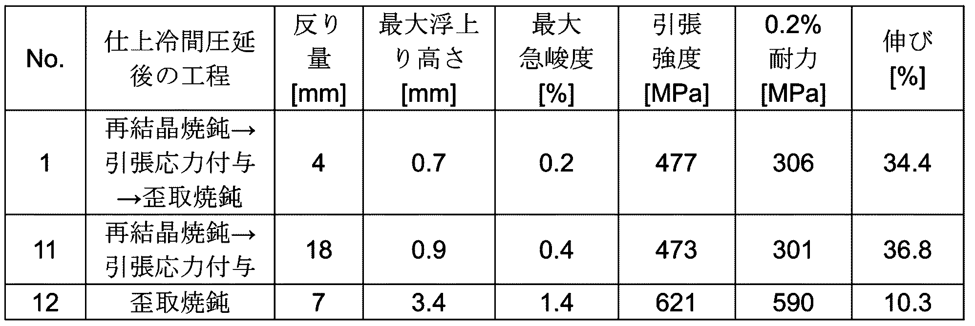
- the process shown in Table 2 was then carried out to produce sample No. 1, which is an example of the present invention, and samples No. 11 and 12, which are comparative examples.
- the recrystallization annealing for the present invention and comparative examples was performed at about 900°C, and shape correction was performed using a tension leveler, but without pressing with a leveler roll, under conditions of a correction tension of about 300 MPa, mainly tensile stress.
- the stress relief annealing temperature for sample No. 1, which is an example of the present invention, and sample No. 12, which is a comparative example was about 630°C.
- test pieces were taken from the sample of the invention example No. 1 prepared, and each test was performed.
- the test results are shown in Table 2.
- the measurement of warpage to confirm the effect of suppressing etching warpage was performed by preparing a cut sample of 150 mm in length and 30 mm in width, removing 1/2 of the plate thickness from one side by etching, and then measuring the amount of warpage when the cut sample was hung from a vertical upper plate and evaluated.
- the cut sample was taken from the center of the width direction of the prepared sample so that the length direction was the rolling direction.
- the etching solution used was an aqueous solution of ferric chloride, and the etching solution at a liquid temperature of 50°C was sprayed to corrode the test piece.
- the maximum floating height was measured using a three-dimensional shape measuring device, and the maximum floating height and maximum steepness were measured from a test piece cut to a length of 800 mm and placed on a horizontal plate. The steepness was calculated from the data recorded in a matrix form of the floating height for each fixed length (width direction: 21 mm, length direction: 8 mm). The tensile strength, 0.2% yield strength and elongation were measured using the test methods specified in JIS-Z2241.
- the specimen of the invention example No. 1 which was subjected to finish cold rolling-recrystallization annealing-shape straightening-stress relief annealing, showed a good etching warpage of 5 mm or less and good mechanical properties (tensile strength: 460 MPa or more, 0.2% proof stress: 280 MPa or more, elongation: 30% or more), and showed very excellent values of maximum floating height of 0.8 mm or less and maximum steepness of 0.3% or less. From this, it was found that the Fe-Ni alloy thin plate obtained by applying the present invention is suitable for carrying out various etching processes. On the other hand, the specimen of the comparative example No.
Landscapes
- Chemical & Material Sciences (AREA)
- Engineering & Computer Science (AREA)
- Mechanical Engineering (AREA)
- Materials Engineering (AREA)
- Metallurgy (AREA)
- Organic Chemistry (AREA)
- Physics & Mathematics (AREA)
- Thermal Sciences (AREA)
- Crystallography & Structural Chemistry (AREA)
- Heat Treatment Of Sheet Steel (AREA)
Abstract
Description
そこで本発明の目的は、厚さが0.5mm以下のFe-Ni系合金薄板において、さらに良好な平坦度と耐エッチング反り性とを有する、Fe-Ni系合金薄板の製造方法を提供することである。
本発明の他の一態様は、質量%で、C:≦0.01%、Si:≦0.5%、Mn:≦1.0%、Ni:28~52%を含有し、残部がFe及び不可避的不純物からなる、厚さ0.5mm以下のFe-Ni系合金薄板であって、前記Fe-Ni系合金薄板から長さ150mm、幅30mmの試料を切り出し、前記試料を片面側からエッチングし、前記試料の板厚の1/2を除去したときの反り量が10mm以下であり、前記Fe-Ni系合金薄板の800mm長さにおける最大浮上り高さが1.5mm以下である、Fe-Ni系合金薄板である。
以下に本発明のFe-Ni系合金薄板の製造方法について説明する。本発明では、例えば、質量%でC:≦0.01%、Si:≦0.5%、Mn:≦1.0%、Ni:28~52%を含有し、残部がFe及び不可避的不純物からなる組成を有する熱間圧延材を準備する。本発明で規定する組成を有するFe-Ni系合金薄板の熱間圧延材は、所望の熱膨張係数を得るために必要な組成を有するものである。上述した組成範囲の規定理由は以下のとおりである。
[C:≦0.01質量%]
Cは、エッチング性に影響を及ぼす元素である。Cが過度に多く含まれるとエッチング性を阻害するため、Cの上限を0.01%とした。下限は0%でも良いが、製造工程上少なからず含まれるものであるため、特に限定しない。
[Si:≦0.5質量%、Mn:≦1.0質量%]
Si、Mnは、通常、脱酸の目的で使用され、Fe-Ni合金に微量含有されているが、過剰に含有すれば偏析を起こし易くなるため、Si:0.5%以下、Mn:1.0%以下とした。好ましいSi量とMn量は、Si:0.1%以下、Mn:0.5%以下である。SiとMnの下限は特に限定しないが、例えばSiは0.01%、Mnは0.05%と設定することができる。
[Ni:28~52質量%]
Niは、熱膨張係数を調整する作用を有し、低熱膨張特性に大きな影響を及ぼす元素である。含有量が28%より少なく、または52%を超えるものでは熱膨張係数を低減させる効果がなくなるため、Niの範囲は28~52%とする。好ましいNi量の下限は30%であり、より好ましいNi量の下限は32%であり、さらに好ましいNi量の下限は34%である。また、好ましいNi量の上限は50%であり、より好ましいNi量の上限は45%であり、さらに好ましいNi量の上限は38%である。上記以外を構成するのはFe及び不可避的不純物である。また本実施形態では、熱膨張特性の調整や高強度を持たせるために、Niの一部をCoで置換することができる。上述した効果を材料に付与させやすくするために、Coの上限は20%と設定することが好ましい。
本実施形態では、前述の組成を有する帯状の冷間圧延用素材を準備する。この冷間圧延用素材は、例えば、前述の組成を有する熱間圧延材に、機械的或いは化学的に酸化層を除去することで得ることが出来る。また、冷間圧延中の冷間圧延材のエッジから割れ等の不良が発生しないように、エッジをトリミング等により整えておいてもよい。また必要に応じて、冷間圧延前の段階で1200℃程度で均質化熱処理を行っても良い。
本発明では、後述する仕上冷間圧延の前に、板厚を調整するために1回以上の中間冷間圧延を施しても良い。本実施形態では中間冷間圧延を導入した場合について説明するが、熱間圧延後の時点で所望の板厚に調整できている場合は、中間冷間圧延を省略してもよい。また、中間冷間圧延後の薄板には、加工硬化した材料を軟化させ、加工歪を除去するために、中間焼鈍を施しても良い。この中間焼鈍の温度は再結晶が促進される800℃以上の温度に設定すればよい。焼鈍時の温度が800℃未満の場合、材料が十分に軟化せず、所望の特性が得られない可能性がある。焼鈍温度の上限は特に限定しないが、過剰に温度を上げ過ぎた場合も所望の特性が得られない可能性が高いため、1100℃程度と設定することができる。このときの加熱保持時間は、材料の組成や板厚に合わせて適宜調整すればよい。尚、この中間焼鈍は、所望の温度に設定された加熱炉に中間冷間圧延後の薄板を連続的に通して行うことができる。例えば、中間冷間圧延後の薄板がロール状に巻かれた状態から引き出し、加熱炉を通り、ロール状に巻き取る方法で行うことができる。
本実施形態の製造方法では、前述した中間冷間圧延後または中間焼鈍後の中間材料に、圧下率5%以上50%以下の仕上冷間圧延を施し、薄板を得る。上述した圧下率の範囲に収めることで、中間材料の中央部と端部との伸び差を縮めることで過大な波形状の発生を抑制し、後述する形状矯正工程後で平坦な形状に調整し易くすることが出来る。圧下率が5%未満の場合、中伸びが発生し、形状矯正後の薄板中央部の平坦度が低下する傾向にある。また圧下率が5%未満の場合、後述する再結晶熱処理において、薄板の再結晶化が過大に促進されやすくなるため、薄板の硬度が低下する傾向にある。圧下率が50%超の場合、端波が強くなり、形状矯正後で平坦度が低下する傾向にある。好ましい圧下率の下限は15%であり、より好ましい圧下率の下限は20%である。また、好ましい圧下率の上限は40%であり、さらに好ましい圧下率の上限は30%である。ここで仕上冷間圧延のパス数は、1パスであることが好ましい。なお本実施形態の製造方法は、幅が300~1100mmの薄板に適用することができる。また、本実施形態に適した板厚は0.5mm以下であり、好ましくは0.3mm以下、より好ましくは0.2mm以下である。なお板厚の下限は特に限定しないが、あまりに薄すぎるとハーフエッチングに不適であるため、例えば0.02mmと設定することができる。好ましくは0.05mm以上であり、より好ましくは0.08mm以上である。
本実施形態では、仕上冷間圧延を終えた薄板(仕上冷延薄板)に対して、800℃~1000℃の温度で焼鈍を行う、再結晶焼鈍工程を行う。この工程により、圧延による加工歪を除去させつつ板の耐力を十分に低下させ、後述する引張応力付与工程において平坦度をより向上させ易くすることができる。ここで再結晶焼鈍時の温度が800℃未満の場合は加工歪を十分に除去することができず、温度が1000℃超の場合は薄板の硬度が下がりすぎる傾向にあるため、好ましくない。好ましい再結晶焼鈍温度の下限は850℃であり、好ましい再結晶焼鈍温度の上限は950℃である。
本実施形態の製造方法では、再結晶焼鈍工程を終えた薄板(再結晶焼鈍薄板)に形状矯正による引張応力付与工程を実施する。これにより再結晶焼鈍薄板に残存している過大な端波や中伸びを矯正し、平坦度を大幅に向上させることが可能となる。特に本発明では、テンションレベラーを用いた形状矯正で付与される曲げ応力を極力付与せず、引張応力主体で矯正することが特徴である。従来はこのような加工歪を除去するために、テンションレベラー等を用いて曲げ応力を付与する形状矯正を行った後、再結晶温度以下で薄板を熱処理する歪取焼鈍を行うことが一般的であった。しかし曲げ応力を付与する形状矯正で薄板に導入された加工歪は、歪取焼鈍でも十分に除去できず、薄板の平坦度低下要因となる可能性があった。本実施形態の引張応力付与工程は、薄板に新たな加工歪を付与させることなく、上述した再結晶焼鈍工程により曲げ応力を付与させなくても平坦度を向上させることが可能となる。この形状矯正に用いる装置は、ストレッチャー、ローラレベラーやテンションレベラー等、従来から用いられている形状矯正装置を使用することができる(本実施形態ではテンションレベラーを使用する)。ただし上述したように引張応力主体で矯正を行うために、例えばテンションレベラーを使用する際には、レベラーロール(矯正ロール)による押し込みを行わなくてもよい。また、レベラーロールによる押し込みを行う場合は、板厚以下の押し込み量にて実施してもよい。ここで形状矯正時の張力は、張力200~600MPaに設定することができる。張力が200MPa未満となる場合、矯正が不十分となる。張力が600MPa超と成る場合、過大な張力により新たな形状不良が発生する可能性がある。好ましい張力の下限は250MPaであり、好ましい張力の上限は500MPaであり、より好ましい張力の上限は450MPaであり、さらに好ましい張力の上限は400MPaである。なお本発明の製造方法では、後述の歪取焼鈍工程によって、調質圧延(軽圧下圧延)を行なわなくても、優れた平坦度や耐エッチング反り特性を有する薄板を製造できるため、引張応力付与工程の前後において調質圧延を省略することが可能である。
本実施形態では、引張応力付与工程後の薄板(形状矯正薄板)に、400℃~750℃の温度で焼鈍を行う、歪取焼鈍工程を実施し、本発明のFe-Ni系合金薄板を得る。本発明では、特許文献3には開示されていないこの「歪取焼鈍工程」を必須とする。本発明の引張応力付与工程は従来と比較して、板材に曲げ応力を極力付与しない工程であるが、依然として板材表層と板厚中央部における応力差が残存していることから、深いエッチング加工を施した際に上述した残留応力が解放され、過大な反りが発生する惧れがある。本実施形態では上述した歪取焼鈍工程を実施することで、引張応力付与工程によって発生した板材の残留応力差を解消し、優れた平坦度を有しつつエッチングによる反りも抑制することが可能なFe-Ni系合金薄板を得ることができる。この本発明の製造方法によれば、好ましい歪取焼鈍温度の下限は500℃であり、好ましい歪取焼鈍温度の上限は700℃である。
<反り量>
本実施形態のFe-Ni系合金用薄板は、長さ方向(圧延方向)に150mm、幅方向(圧延直角方向)に30mmの試料サイズに切断した際、前記試料の板厚の1/2を除去した際における反り量が10mm以下であることを特徴とする。これにより、本実施形態の薄板は板厚中央の位置における残留応力が低減されており、応力のバランスがより崩れる板厚中央の深さまでエッチングを行っても板材の変形を抑制することが可能であり、良好にエッチング加工を進行させつつ、形状精度を確保することが可能である。このように特許文献3に記載されている板厚の1/3を除去するよりも反りの影響が生じやすい、板厚の1/2を除去した際の反り量が10mm以下であれば、複雑形状かつ深い断面位置の残留ひずみも解放されているとみなすことができ、多様なエッチングを施すための素材として好適である。より好ましい反り量の上限は、7mmであり、さらに好ましい反り量の上限は5mmである。なお本実施形態では、長手方向が圧延方向となるように試料を切断して長さ150mm、幅30mmのカットサンプルを作成し、板厚の1/2を片面側からエッチングで除去した後、カットサンプルの長さ方向の一端(上端)を垂直定盤に接する状態で吊り下げ、反りにより垂直定盤から離れたカットサンプルの他端(下端)と、垂直定盤との水平距離を反り量として測定している。本実施形態では、エッチング面が凹側に反った場合を「+」の反り、エッチング面が凸側に反った場合を「-」の反りとしている。この反り量は絶対値で評価し、絶対値が小さいほど好ましい。なお本実施形態では、幅方向(圧延直角方向)に150mm、長さ方向(圧延方向)に30mmの試料サイズに切断した際、前記試料の板厚の1/2を除去した際における反り量が10mm以下(より好ましくは7mm以下、さらに好ましくは5mm以下)であることが好ましい。
本実施形態のFe-Ni系合金薄板は、800mm長さにおける最大浮上り高さも従来品より低くすることが可能である。具体的にはFe-Ni系合金薄板の長さを800mmとした際の最大浮上り高さが1.5mm以下である。このように、上述した本発明の製造方法を実施することで得られる薄板は、幅が800mm以上(好ましくは900mm以上、より好ましくは1000mm以上)といった広幅な薄板材においても、優れた平坦度を有し、例えばエッチング加工における寸法精度向上といった効果が発揮できる傾向にある。より好ましい最大浮上がり高さの値は1.2mm以下であり、さらに好ましい最大浮上り高さの値は1.0mm以下である。最大浮上り高さの下限は特に限定しないが、全く平坦な形状を製造することは極めて困難であることから、例えば最大浮上り高さの下限を0.1mm程度としてもよく、なお浮上り高さの測定は、薄板を800mm長さに切断し、水平定盤上に置き、レーザー変位計等を用いて、薄板の浮上り高さを測定すればよい。
本実施形態のFe-Ni系合金薄板は、800mm長さにおける最大急峻度が0.7%以下であることが好ましい。この規定を満たす本発明のFe-Ni系合金薄板は、より優れた平坦度を有する。より好ましい最大急峻度の値は0.5%以下であり、さらに好ましい最大急峻度の値は0.3%以下である。最大急峻度の下限も特に限定しないが、浮上り高さと同様、全く平坦な形状を製造することは極めて困難であることから、例えば最大急峻度の下限を0.01%程度としてもよい。なお急峻度の測定は、板幅および板長さ方向で、一定長さごとで浮上り高さをマトリックス状に記録したデータから、急峻度を算出すれば良い。
本実施形態のFe-Ni系合金薄板は、引張強度が400MPa以上、0.2%耐力が200MPa以上であることが好ましい。また加工性を重視する場合、伸びは20~50%と設定してもよい。これにより本実施形態のFe-Ni系合金薄板は、優れた平坦度および耐エッチング反り性に加えて、より優れた塑性加工性を発揮することが可能であり、巻取り時や塑性加工時の破断や亀裂がより発生し難くなる傾向にある。好ましい引張強度の下限は450MPaであり、好ましい0.2%耐力の下限は250MPaである。また好ましい伸びの下限は25%であり、好ましい伸びの上限は45%である。なお引張強度、0.2%耐力、および伸び特性は、JIS-Z2241に規定された方法に基づいた試験により求めることができる。

Claims (2)
- 質量%で、C:≦0.01%、Si:≦0.5%、Mn:≦1.0%、Ni:28~52%を含有し、残部がFe及び不可避的不純物からなる冷間圧延用素材に対して、圧下率5%~50%の仕上冷間圧延を施して薄板とする仕上冷間圧延工程と、
前記仕上冷間圧延後の薄板に、800℃以上1000℃以下の温度で焼鈍を行う再結晶焼鈍工程と、
前記再結晶焼鈍工程後の薄板に、張力200~600MPaの条件で形状矯正を行い、引張応力を付与する、引張応力付与工程と、
前記引張応力付与工程後の薄板に、400℃以上750℃以下の温度で歪取焼鈍を行う、歪取焼鈍工程を備え、厚さ0.5mm以下のFe-Ni系合金薄板を得る、Fe-Ni系合金薄板の製造方法。 - 質量%で、C:≦0.01%、Si:≦0.5%、Mn:≦1.0%、Ni:28~52%を含有し、残部がFe及び不可避的不純物からなる、厚さ0.5mm以下のFe-Ni系合金薄板であって、
前記Fe-Ni系合金薄板から長さ150mm、幅30mmの試料を切り出し、前記試料を片面側からエッチングし、前記試料の板厚の1/2を除去したときの反り量が10mm以下であり、
前記Fe-Ni系合金薄板の800mm長さにおける最大浮上り高さが1.5mm以下である、Fe-Ni系合金薄板。
Priority Applications (3)
| Application Number | Priority Date | Filing Date | Title |
|---|---|---|---|
| JP2025556417A JPWO2025100438A1 (ja) | 2023-11-07 | 2024-11-06 | |
| KR1020267017556A KR20260089647A (ko) | 2023-11-07 | 2024-11-06 | Fe-Ni계 합금 박판의 제조 방법 및 Fe-Ni계 합금 박판 |
| CN202480070139.5A CN122122320A (zh) | 2023-11-07 | 2024-11-06 | Fe-Ni系合金薄板的制造方法及Fe-Ni系合金薄板 |
Applications Claiming Priority (2)
| Application Number | Priority Date | Filing Date | Title |
|---|---|---|---|
| JP2023189925 | 2023-11-07 | ||
| JP2023-189925 | 2023-11-07 |
Publications (1)
| Publication Number | Publication Date |
|---|---|
| WO2025100438A1 true WO2025100438A1 (ja) | 2025-05-15 |
Family
ID=95695288
Family Applications (1)
| Application Number | Title | Priority Date | Filing Date |
|---|---|---|---|
| PCT/JP2024/039415 Pending WO2025100438A1 (ja) | 2023-11-07 | 2024-11-06 | Fe-Ni系合金薄板の製造方法およびFe-Ni系合金薄板 |
Country Status (4)
| Country | Link |
|---|---|
| JP (1) | JPWO2025100438A1 (ja) |
| KR (1) | KR20260089647A (ja) |
| CN (1) | CN122122320A (ja) |
| WO (1) | WO2025100438A1 (ja) |
Citations (6)
| Publication number | Priority date | Publication date | Assignee | Title |
|---|---|---|---|---|
| JPS63204541A (ja) | 1987-02-20 | 1988-08-24 | Fujitsu Ltd | フロツピイデイスク媒体の支持構造 |
| JPH10204541A (ja) * | 1997-01-17 | 1998-08-04 | Nkk Corp | 板形状および耐熱収縮性に優れた低熱膨張合金薄板の製 造方法 |
| JP2003253398A (ja) | 2002-02-28 | 2003-09-10 | Jfe Steel Kk | エッチング速度とエッチング精度に優れた低熱膨張合金薄板およびその製造方法 |
| JP2006097073A (ja) * | 2004-09-29 | 2006-04-13 | Hitachi Metals Ltd | Fe−Ni系合金薄板材の製造方法 |
| WO2018235862A1 (ja) * | 2017-06-20 | 2018-12-27 | 日立金属株式会社 | メタルマスク用薄板の製造方法及びメタルマスク用薄板 |
| JP2021014639A (ja) | 2019-07-10 | 2021-02-12 | 日立金属株式会社 | Fe−Ni系合金薄板の製造方法 |
-
2024
- 2024-11-06 CN CN202480070139.5A patent/CN122122320A/zh active Pending
- 2024-11-06 WO PCT/JP2024/039415 patent/WO2025100438A1/ja active Pending
- 2024-11-06 KR KR1020267017556A patent/KR20260089647A/ko active Pending
- 2024-11-06 JP JP2025556417A patent/JPWO2025100438A1/ja active Pending
Patent Citations (6)
| Publication number | Priority date | Publication date | Assignee | Title |
|---|---|---|---|---|
| JPS63204541A (ja) | 1987-02-20 | 1988-08-24 | Fujitsu Ltd | フロツピイデイスク媒体の支持構造 |
| JPH10204541A (ja) * | 1997-01-17 | 1998-08-04 | Nkk Corp | 板形状および耐熱収縮性に優れた低熱膨張合金薄板の製 造方法 |
| JP2003253398A (ja) | 2002-02-28 | 2003-09-10 | Jfe Steel Kk | エッチング速度とエッチング精度に優れた低熱膨張合金薄板およびその製造方法 |
| JP2006097073A (ja) * | 2004-09-29 | 2006-04-13 | Hitachi Metals Ltd | Fe−Ni系合金薄板材の製造方法 |
| WO2018235862A1 (ja) * | 2017-06-20 | 2018-12-27 | 日立金属株式会社 | メタルマスク用薄板の製造方法及びメタルマスク用薄板 |
| JP2021014639A (ja) | 2019-07-10 | 2021-02-12 | 日立金属株式会社 | Fe−Ni系合金薄板の製造方法 |
Also Published As
| Publication number | Publication date |
|---|---|
| CN122122320A (zh) | 2026-05-29 |
| KR20260089647A (ko) | 2026-06-15 |
| JPWO2025100438A1 (ja) | 2025-05-15 |
Similar Documents
| Publication | Publication Date | Title |
|---|---|---|
| JP7156279B2 (ja) | メタルマスク用薄板の製造方法及びメタルマスク用薄板 | |
| JP7532826B2 (ja) | Fe-Ni系合金薄板の製造方法 | |
| JP6598007B2 (ja) | Fe−Ni系合金薄板の製造方法 | |
| JP5294072B2 (ja) | エッチング加工用素材の製造方法及びエッチング加工用素材 | |
| JP6646882B2 (ja) | メタルマスク用素材およびその製造方法 | |
| CN108713067B (zh) | 马氏体系不锈钢箔及其制造方法 | |
| JP2015193871A (ja) | Fe−Ni系合金薄板及びその製造方法 | |
| JP3573047B2 (ja) | エッチング後の平坦性に優れたステンレス鋼板の製造方法 | |
| JP2017064764A (ja) | Fe−Ni系合金薄板及びその製造方法 | |
| JPWO2018043641A1 (ja) | メタルマスク用素材およびその製造方法 | |
| JP5679580B2 (ja) | 圧延銅箔 | |
| JP6975391B2 (ja) | Fe−Ni系合金薄板の製造方法およびFe−Ni系合金薄板 | |
| KR102244229B1 (ko) | Fe-Ni계 합금 박판의 제조 방법 및 Fe-Ni계 합금 박판 | |
| JP7535843B2 (ja) | チタン銅板、プレス加工品およびプレス加工品の製造方法 | |
| WO2023243710A1 (ja) | Fe-Ni系合金薄板の製造方法およびFe-Ni系合金薄板 | |
| JP5943105B2 (ja) | 鋼板およびその製造方法 | |
| JP2020163401A (ja) | Fe−Ni系合金薄板の製造方法およびFe−Ni系合金薄板 |
Legal Events
| Date | Code | Title | Description |
|---|---|---|---|
| 121 | Ep: the epo has been informed by wipo that ep was designated in this application |
Ref document number: 24888732 Country of ref document: EP Kind code of ref document: A1 |
|
| ENP | Entry into the national phase |
Ref document number: 2025556417 Country of ref document: JP Kind code of ref document: A |
|
| ENP | Entry into the national phase |
Ref document number: 1020267017556 Country of ref document: KR Free format text: ST27 STATUS EVENT CODE: A-0-1-A10-A15-NAP-PA0105 (AS PROVIDED BY THE NATIONAL OFFICE) |
|
| WWE | Wipo information: entry into national phase |
Ref document number: 1020267017556 Country of ref document: KR |
|
| ENP | Entry into the national phase |
Ref document number: 2024888732 Country of ref document: EP Effective date: 20260608 |
|
| WWE | Wipo information: entry into national phase |
Ref document number: 2024888732 Country of ref document: EP |
|
| NENP | Non-entry into the national phase |
Ref country code: DE |
|
| WWP | Wipo information: published in national office |
Ref document number: 1020267017556 Country of ref document: KR |