WO2025100413A1 - ペット用システムトイレ - Google Patents
ペット用システムトイレ Download PDFInfo
- Publication number
- WO2025100413A1 WO2025100413A1 PCT/JP2024/039314 JP2024039314W WO2025100413A1 WO 2025100413 A1 WO2025100413 A1 WO 2025100413A1 JP 2024039314 W JP2024039314 W JP 2024039314W WO 2025100413 A1 WO2025100413 A1 WO 2025100413A1
- Authority
- WO
- WIPO (PCT)
- Prior art keywords
- excretion
- surface portion
- wall portion
- pet toilet
- casing
- Prior art date
- Legal status (The legal status is an assumption and is not a legal conclusion. Google has not performed a legal analysis and makes no representation as to the accuracy of the status listed.)
- Pending
Links
Images




Classifications
-
- A—HUMAN NECESSITIES
- A01—AGRICULTURE; FORESTRY; ANIMAL HUSBANDRY; HUNTING; TRAPPING; FISHING
- A01K—ANIMAL HUSBANDRY; AVICULTURE; APICULTURE; PISCICULTURE; FISHING; REARING OR BREEDING ANIMALS, NOT OTHERWISE PROVIDED FOR; NEW BREEDS OF ANIMALS
- A01K1/00—Housing animals; Equipment therefor
- A01K1/01—Removal of dung or urine ; Removal of manure from stables
Definitions
- This disclosure relates to a system toilet for pets.
- Patent Document 1 discloses a pet toilet that includes a side wall with an inlet, an odor suction chamber formed on the outside of the side wall, an exhaust port formed in the suction chamber facing the inlet, and a fan attached to the exhaust port.
- the fan is operated to ventilate the excretion space of the toilet, thereby preventing the odor of excrement from building up in the excretion space.
- it is desirable to increase the ventilation capacity and improve the deodorizing performance of the excretion space.
- increasing the ventilation capacity of the fan increases the operating noise of the fan, which can discourage pets from using the toilet.
- the present disclosure therefore aims to provide a pet toilet system that is both quiet and has deodorizing performance.
- the pet toilet system includes an excretion platform having a liquid-permeable excretion surface, a base supporting the excretion platform and having a tray for receiving pet excreta that has passed over the excretion surface, an upper cover arranged above the excretion platform and having an entrance/exit for pets and a ventilation opening for ventilation, defining an excretion space between the excretion platform and the upper cover, and a blower fan that exhausts air in the excretion space through the ventilation opening, the blower fan is capable of ventilating the air in the excretion space within one minute, and the sound pressure in the excretion space when the blower fan is operating is 75 dB or less.
- Blower fans have higher static pressure characteristics than axial fans such as propeller fans, so they can achieve a high exhaust volume with a low rotation speed. Therefore, by using a blower fan, the air in the excretion space can be ventilated within one minute, and the sound pressure in the excretion space when the blower fan is operating can be reduced to 75 dB or less. This makes it possible to achieve both quietness and deodorizing performance.
- the excretion surface may have a plurality of openings through which excrement passes, and the ventilation opening may be disposed above the plurality of openings. By disposing the ventilation opening above the plurality of openings, odors from excretion can be effectively discharged from the ventilation opening.
- the upper cover includes a front wall portion having an entrance, a rear wall portion facing the front wall portion in the depth direction, a pair of side wall portions facing each other in the width direction perpendicular to the depth direction, and an upper wall portion facing the excretion surface in the up-down direction perpendicular to the width direction and the depth direction, and the ventilation hole may be formed in the upper wall portion.
- the ventilation hole By forming the ventilation hole in the upper wall portion, the odor of excreta can be effectively discharged from the excretion space.
- dust from the litter is less likely to be sucked in, which can prevent the blower fan from getting dirty.
- the pet toilet system includes a fan unit having a casing that houses a blower fan, and the fan unit may be removably attached to the upper wall of the upper cover. By removably attaching the fan unit to the upper cover, it becomes possible to remove the fan unit from the upper cover and clean it, thereby preventing a decrease in ventilation capacity due to dirt on the blower fan.
- the casing has a bottom surface facing the upper wall portion, a top surface facing the opposite side to the bottom surface, and a peripheral surface connecting the bottom surface and the top surface, the bottom surface having an intake port facing the ventilation port, the peripheral surface having an exhaust port for exhausting air taken in from the intake port to the outside of the casing, and the casing may have an exhaust path extending between the intake port and the exhaust port.
- the peripheral portion may include a front portion, a rear portion facing the opposite side of the front portion, a first side portion facing one side in the width direction, and a second side portion facing the other side in the width direction, and the exhaust port may be formed in the rear portion.
- the upper wall portion may have a mating recess recessed toward the excretion surface, and the bottom surface portion of the casing may have a mating protrusion protruding toward the upper wall and mating with the mating recess.
- the mating protrusion of the casing mating with the mating recess of the upper wall allows the fan unit to be properly attached to the upper cover.
- the mating protrusion may have a claw portion that fixes the casing to the upper wall portion. Fixing the casing to the upper wall portion by the claw portion can prevent the fan unit from falling off the upper cover.
- the rotation axis of the blower fan may be positioned at a position offset from the center point of the bottom surface when viewed from the top-bottom direction. By positioning the rotation axis of the blower fan offset from the center point of the bottom surface, the cross-sectional area of the exhaust path can be increased, thereby improving the ventilation capacity of the blower fan.
- the upper cover includes a front wall portion having an entrance and exit, a rear wall portion facing the front wall portion in the depth direction, and a pair of side wall portions facing each other in the width direction perpendicular to the depth direction, and the ventilation hole may be formed in the rear wall portion.
- the ventilation opening may be located above the middle position of the rear wall in the up-down direction perpendicular to the width and depth directions. By forming the ventilation opening above the middle position of the rear wall, the odor of excrement can be effectively discharged from the excrement space. In addition, when litter is placed on the excrement platform, dust from the litter is less likely to be sucked in, which reduces contamination of the blower fan.
- the ventilation opening may be located below the middle position of the rear wall in the up-down direction perpendicular to the width and depth directions. In this case, the ventilation opening is located close to the pet waste, so that the odor from the waste can be effectively discharged from the ventilation opening.
- the device may be provided with a fan unit having a casing that houses a blower fan, and the fan unit may be removably attached to the rear wall of the upper cover. Making the fan unit removable allows the fan unit to be removed and cleaned, thereby preventing a decrease in ventilation capacity due to contamination of the blower fan.
- the casing has a bottom surface facing the rear wall, a top surface facing the opposite side to the bottom surface, and a peripheral surface connecting the bottom surface and the top surface, the bottom surface having an intake port facing the ventilation port, the peripheral surface having an exhaust port for exhausting air taken in from the intake port to the outside of the casing, and the casing may have an exhaust path extending between the intake port and the exhaust port.
- the peripheral surface portion may include an upper surface portion facing upward, a lower surface portion facing downward, a first side portion facing one side in the width direction, and a second side portion facing the other side in the width direction, and the exhaust port may be formed in the upper surface portion.
- the exhaust port is prevented from being blocked by the wall when the system toilet is installed next to a wall.
- the diameter of the blower fan may be 12 cm or more.
- the front wall portion includes a straightening portion formed along the edge of the entrance/exit, and the straightening portion may have a V-shape that widens toward the excretion space in a cross-sectional view parallel to the excretion surface.
- the device may further include a deodorizing filter that covers the ventilation opening.
- This deodorizing filter may contain activated carbon. In this case, it can adsorb and remove odors in the exhaust air.
- the deodorizing filter may have an airflow resistance value of 0.01 kPa ⁇ s/m or more and 0.25 kPa ⁇ s/m or less. By making the airflow resistance value 0.01 kPa ⁇ s/m or more, the deodorizing effect can be improved. By making the airflow resistance value 0.25 kPa ⁇ s/m or less, pressure loss during exhaust can be suppressed, and a decrease in the ventilation capacity of the blower fan can be suppressed.
- the deodorizing filter may be arranged parallel to the excretion surface. In this case, the deodorizing filter is prevented from twisting or rippling during exhaust, and the deterioration of the deodorizing performance can be suppressed.
- the casing has a protruding tubular section that protrudes from the bottom surface toward the upper wall section and defines the air intake, and the tip of the protruding tubular section may abut against the deodorizing filter.
- the exhaust gas that passes through the ventilation opening will reliably pass through the deodorizing filter, improving the deodorizing performance.
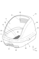
- FIG. 2 is an exploded perspective view showing the main components of the pet toilet system according to one embodiment.
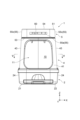
- FIG. 2 is a front view of the pet toilet system.
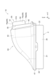
- FIG. 2 is a side view of the pet toilet system.
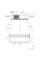
- FIG. 2 is a rear view of the pet toilet system.
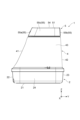
- 3 is a cross-sectional view of the pet toilet system taken along line VV in FIG. 2.
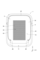
- FIG. 2 is a top view of the system toilet for pets with the fan unit removed.
- FIG. FIG. FIG. 11 is a perspective view showing a system toilet for pets according to another embodiment with the fan unit removed.
- FIG. 2 is a side view of the pet toilet system.
- FIG. 13 shows the results of a suction test.
- FIG. 1 is an exploded perspective view showing the main components of a pet system toilet (hereinafter referred to as the "system toilet") 1 according to one embodiment.
- FIG. 2 is a front view of the system toilet 1.
- FIG. 3 is a side view of the system toilet 1.
- FIG. 4 is a rear view of the system toilet 1.
- the system toilet 1 shown in Figures 1 to 4 is an excretion device for pets.
- pets broadly include vertebrates and invertebrates, and typically include pet animals such as dogs, cats, rabbits, and hamsters.
- the system toilet 1 is installed indoors for pets kept indoors, and provides an excretion space.
- Pet waste is typically urine, but also includes bodily fluids such as low-viscosity feces, saliva, and blood.
- the system toilet 1 includes a base 2, an excretion tray 3, an upper cover 4, and a fan unit 5.
- the excretion tray 3 is disposed on the base 2.
- the upper cover is disposed on the excretion tray 3.
- the fan unit 5 is disposed on the upper cover 4.
- the stacking direction of the base 2, excretion table 3, upper cover 4, and fan unit 5 is referred to as the "vertical direction Z,” and the two directions perpendicular to the vertical direction Z are referred to as the "width direction X” and the “depth direction Y,” respectively.
- the width direction X is a direction parallel to the short side of the system toilet 1 when viewed from the front.
- the depth direction Y is a direction perpendicular to the width direction X and the vertical direction Z.
- one side of the depth direction Y may be referred to as the "front,” and the other side of the depth direction Y may be referred to as the “rear.”
- the direction from the base 2 to the fan unit 5 may be referred to as the “upper,” and the direction from the fan unit 5 to the base 2 may be referred to as the “lower.”
- the base 2 is a container with an open top, and includes a bottom surface 21, a front wall portion 22, a rear wall portion 23, and a pair of side walls 24.
- the bottom surface 21 has a substantially rectangular planar shape, and is disposed opposite the installation surface (e.g., the floor surface) of the system toilet 1.
- the front wall portion 22, the rear wall portion 23, and the pair of side walls 24 are erected from the periphery of the bottom surface 21.
- the front wall portion 22 and the rear wall portion 23 face each other in the depth direction Y, and substantially extend in the up-down direction Z.
- the pair of side walls 24 face each other in the width direction X, and substantially extend in the up-down direction Z. Both ends of the front wall portion 22 and the rear wall portion 23 in the width direction X are connected to both ends of the pair of side walls 24 in the depth direction Y.
- the base 2 includes a tray 25 that receives pet waste.
- the tray 25 is housed within the base 2 so that it can slide in the depth direction Y.
- An absorbent sheet that absorbs waste is placed on the tray 25 by a user (e.g., a pet owner).
- the front wall 22 of the base 2 may be formed with a recess for inserting a hand. The user can insert their hand into the recess in the front wall 22 and slide the tray 25 forward to pull out the tray 25 from the base 2 as shown in FIG. 1.
- the excretion platform 3 is a container with an open top, and includes a bottom surface 31 and a wall surface 32.
- the bottom surface 31 and the wall surface 32 are integrally formed, for example, from a thermoplastic resin.
- the bottom surface 31 provides an excretion surface 33 on which the pet sits when excreting.
- Litter may be placed on the excretion surface 33 of the bottom surface 31.
- Litter is a granular material that can absorb or pass through excrement such as urine.
- litter made of bentonite or water-repellent coated wood or paper that can cover feces and absorb liquids, or zeolite, silica gel, minerals, etc. with deodorizing power, molded into an approximately spherical shape of several mm to several cm is used.
- the bottom surface 31 has a generally rectangular planar shape and has multiple bars arranged like a slatted platform. A number of openings 34 are regularly formed between the multiple bars. The multiple openings 34 are arranged above the tray 25 and are able to pass pet waste.
- the wall surface 32 rises upward from the periphery of the bottom surface 21.
- the wall surface 32 of the excretion platform 3 is supported on the base 2. When a pet excretes on the excretion surface 33, the waste passes through the multiple openings 34 and falls into the tray 25, where it is absorbed by an absorbent sheet arranged on the tray 25.
- the upper cover 4 is disposed above the excretion table 3.
- the upper cover 4 is a so-called full-cover type container, and includes a front wall 41, a rear wall 42, a pair of side walls 43, and an upper wall 44.
- the front wall 41, the rear wall 42, the pair of side walls 43, and the upper wall 44 are integrally formed, for example, from a thermoplastic resin.
- the front wall 41 and the rear wall 42 face each other in the depth direction Y, and substantially extend in the vertical direction Z.
- the pair of side walls 43 face each other in the width direction X, and substantially extend in the vertical direction Z. Both ends of the front wall 41 and the rear wall 42 in the width direction X are connected to both ends of the pair of side walls 43 in the depth direction Y.
- the lower ends of the front wall 41, the rear wall 42, and the pair of side walls 43 are spread out in a skirt shape.
- the front wall 41 is disposed above the front wall 22 of the base 2 via the wall surface 32 of the excretion table 3.
- the rear wall 42 is disposed above the rear wall 23 of the base 2 via the wall surface 32 of the excretion table 3.
- the pair of side walls 43 are disposed above the pair of side walls 24 of the base 2 via the wall surface 32 of the excretion table 3.
- the upper wall 44 is connected to the upper ends of the front wall 41, the rear wall 42, and the pair of side walls 43.
- the lower part of the upper cover 4 is open.
- the upper cover 4 defines an excretion space 10 between the excretion platform 3 and the upper cover 4.
- the excretion space 10 is a space defined by the excretion platform 3, a front wall 41, a rear wall 42, a pair of side walls 43, and an upper wall 44.
- the excretion space 10 has a volume according to the size of the pet. For example, the volume of the excretion space 10 is 0.02 m3 or more and 0.10 m3 or less.
- the excretion space 10 communicates with the internal space of the base 2 via a plurality of openings 34 in the excretion surface 33.
- the front wall portion 41, the rear wall portion 42, the pair of side wall portions 43, and the upper wall portion 44 may each be inclined inwardly upward so that the cross-sectional area perpendicular to the vertical direction Z of the excretion space 10 decreases upward.
- the inclination angle of the front wall portion 41 with respect to a plane perpendicular to the vertical direction Z (XY plane) may be greater than the inclination angle of the rear wall portion 42 with respect to the plane perpendicular to the vertical direction Z (XY plane).
- the upper cover 4 has an entrance 11 for pets.
- the entrance 11 is an opening for pets to enter and exit the excretion space 10, and is formed in the front wall portion 41 of the upper cover 4.
- the entrance 11 has, for example, a roughly rectangular shape when viewed from the front, and has dimensions according to the size of the pet.
- the entrance 11 may be formed continuously from the front wall portion 41 to a pair of side wall portions 43.
- FIG. 5 is a cross-sectional view taken along line V-V in FIG. 2.
- the front wall portion 41 of the upper cover 4 may include a straightening portion 48 formed along the edge of the entrance/exit 11.
- the straightening portion 48 has a V-shaped cross-sectional shape that widens toward the excretion space 10, and extends in the vertical direction Z.
- the straightening portion 48 has the function of straightening the airflow flowing from the entrance/exit 11 into the excretion space 10 when the blower fan 52 described below is activated, and suppresses odors within the excretion space 10 from escaping to the outside through the entrance/exit 11.
- the upper cover 4 has, in addition to the entrance/exit 11, a ventilation opening 12 for ventilation.
- the ventilation opening 12 is an opening for discharging air in the excretion space 10 to the outside of the system toilet 1, and is formed in the upper wall portion 44 of the upper cover 4.
- Figure 6 is a top view of the system toilet 1 with the fan unit 5 removed.
- the upper wall portion 44 is formed with a substantially rectangular ventilation opening 12.
- the ventilation opening 12 is connected to the entrance/exit 11 via the excretion space 10.
- the center position of the ventilation opening 12 extends in the vertical direction Z, and is positioned at a position offset from the central axis AX that passes through the center of the upper wall portion 44 in a plan view.
- the ventilation opening 12 is provided with a lattice- or slat-shaped ventilation plate 45 to prevent the intrusion of foreign objects.
- the ventilation plate 45 is arranged parallel to the excretion surface 33 so as to cover the ventilation opening 12, and has a number of slit-shaped openings that allow exhaust air from the excretion space 10 to pass through.
- the ventilation plate 45 is removably attached to the upper wall portion 44 via an engagement mechanism such as a latch. Therefore, the ventilation plate 45 can be removed from the upper wall portion 44 and cleaned.
- the system toilet 1 is further provided with a deodorizing filter 50 that is disposed between the upper cover 4 and the fan unit 5 and covers the ventilation opening 12.
- the deodorizing filter 50 is disposed on the ventilation plate 45 and removes odors from the air passing through the ventilation opening 12.
- the deodorizing filter 50 is disposed parallel to the excretion surface 33. This prevents the deodorizing filter 50 from being twisted or wavy when exhausting air.
- the deodorizing filter 50 is disposed upstream of a blower fan 52, which will be described later, in the flow direction of the exhaust air.
- the deodorizing filter 50 includes, for example, fibers carrying activated carbon that adsorbs odors.
- the density of the deodorizing filter 50 may be 0.007 g/cm 3 to 0.075 g/cm 3.
- the basis weight of the deodorizing filter 50 may be 40 gsm to 200 gsm, more preferably 70 gsm to 160 gsm.
- the deodorizing filter 50 may have an airflow resistance value of 0.01 kPa ⁇ s/m or more and 0.25 kPa ⁇ s/m or less.
- the airflow resistance value can be measured by a known method. For example, a test piece of a predetermined size is cut out from the deodorizing filter 50, and the airflow resistance value of the test piece is measured using a Kato Tech Co., Ltd. air permeability tester (KES-F8) or an equivalent air permeability tester. For example, air is discharged and sucked through the test piece at a constant flow rate, and the integral value of the pressure loss measured using a semiconductor differential pressure gauge is taken as the airflow resistance value.
- KES-F8 air permeability tester
- the measurement of the airflow resistance value is then repeated multiple times (for example, five times), and the average value can be taken as the airflow resistance value of the deodorizing filter 50.
- the airflow resistance value of the deodorizing filter 50 0.01 kPa ⁇ s/m or more, the air passing through the ventilation opening 12 can be effectively brought into contact with the fibers of the deodorizing filter 50.
- the airflow resistance of the deodorizing filter 50 0.25 kPa ⁇ s/m or less, pressure loss during exhaust can be suppressed, and as a result, the rotation speed of the blower fan 52, which will be described later, can be reduced.
- the upper wall portion 44 has a mating recess 46 recessed downward (toward the excretion surface 33).
- the mating recess 46 has a generally circular recess bottom surface 46a centered on the central axis AX when viewed from above, and a recess side surface 46b standing upright from the recess bottom surface 46a and connected to the peripheral portion 44a of the upper wall portion 44.
- the recess bottom surface 46a is positioned lower than the peripheral portion 44a of the upper wall portion 44.
- the ventilation opening 12 is formed in the recess bottom surface 46a.
- the recess side surface 46b has a plurality of cutouts 62 cut out radially outward from the recess bottom surface 46a. The plurality of cutouts 62 are arranged along the circumferential direction around the central axis AX.
- the fan unit 5 is removably attached to the upper wall portion 44 of the upper cover 4.
- the fan unit 5 includes a casing 51 and a blower fan 52.
- the casing 51 has a generally quadrangular pyramid shape and has a bottom surface portion 53, a top surface portion 54 facing the opposite side to the bottom surface portion 53, and a peripheral surface portion 55 connecting the bottom surface portion 53 and the top surface portion 54.
- the bottom surface portion 53 is disposed opposite the upper wall portion 44 of the upper cover 4.
- the peripheral portion 55 includes a front portion 55a, a back portion 55b, and a pair of side portions 55c.
- the front portion 55a faces forward in the depth direction Y
- the back portion 55b faces backward in the depth direction Y.
- the pair of side portions 55c face outward in the width direction X.
- the front portion 55a and the back portion 55b face each other in the depth direction Y, and essentially extend in the up-down direction Z.
- the pair of side portions 55c face each other in the width direction X, and essentially extend in the up-down direction Z. Both ends of the front portion 55a and the back portion 55b in the width direction X are connected to both ends of the pair of side portions 55c in the depth direction Y.
- the front portion 55a is inclined inwardly as it goes upwards, so as to form a smooth outline together with the front wall portion 41 of the upper cover 4, when viewed from the width direction X.
- the back portion 55b is inclined inwardly as it goes upwards, so as to form a smooth outline together with the rear wall portion 42 of the upper cover 4, when viewed from the width direction X.
- the pair of side portions 55c are inclined inwardly as it goes upwards, so as to form a smooth outline together with the pair of side wall portions 43 of the upper cover 4, when viewed from the depth direction Y.
- the inclination angles of the front portion 55a, the back portion 55b, and the pair of side portions 55c with respect to a plane perpendicular to the vertical direction Z (XY plane) are the same as the inclination angles of the front wall portion 41, the rear wall portion 42, and the pair of side walls with respect to a plane perpendicular to the vertical direction Z (XY plane).
- the front portion 55a is provided with an operation panel 60 that accepts operation inputs from the user.
- the system toilet 1 is equipped with a control device that controls the operation, stoppage, and rotation speed of the blower fan 52 in response to the operation of the operation panel 60 by the user.
- FIG. 7 is a bottom view of the fan unit 5.
- an air intake 13 is formed in the bottom surface 53 of the casing 51.
- the air intake 13 is a substantially circular opening for introducing exhaust air from the excretion space 10 into the casing 51.
- a lattice- or grate-shaped guard 56 is provided on the air intake 13 to prevent foreign matter from entering the inside of the casing 51.
- the air intake 13 is formed in a position corresponding to the ventilation opening 12. In other words, when the fan unit 5 is attached to the upper cover 4, the air intake 13 is aligned with the ventilation opening 12 formed in the upper wall portion 44. When viewed from the vertical direction Z, the center position of the air intake 13 is offset from the central axis AX.
- the casing 51 also has a cylindrical protruding tubular portion 68 that protrudes downward from the bottom surface portion 53 towards the upper wall portion 44.
- the protruding tubular portion 68 defines the air intake 13.
- the tip of the protruding tubular portion 68 abuts against the deodorizing filter 50 in the thickness direction.
- the deodorizing filter 50 is sandwiched between the protruding tubular portion 68 and the ventilation plate 45. This ensures that exhaust air that has passed through the ventilation opening 12 passes through the deodorizing filter 50.
- the bottom surface portion 53 is provided with a plurality of mating protrusions 57 arranged in a circumferential direction about the central axis AX and protruding downward from the bottom surface portion 53 (toward the upper wall portion 44).
- Each of the plurality of mating protrusions 57 extends in an arc shape in a circumferential direction about the central axis AX.
- the plurality of mating protrusions 57 have a shape corresponding to the mating recesses 46 formed in the upper wall portion 44, and when the fan unit 5 is placed on the upper cover 4, the plurality of mating protrusions 57 are fitted into the mating recesses 46.
- the multiple mating protrusions 57 may each have multiple claws 58 that protrude radially from the central axis AX.
- the multiple claws 58 engage with the multiple cutouts 62, and the fan unit 5 is fixed to the upper cover 4. This prevents the fan unit 5 from falling off the upper cover 4.
- the engagement between the multiple claws 58 and the multiple cutouts 62 is released, and the fan unit 5 can be removed from the upper cover 4.
- the multiple claws 58 and the multiple cutouts 62 form a locking mechanism that fixes the fan unit 5 to the upper cover 4.
- FIG. 8 is a rear view of the fan unit 5. As shown in FIGS. 4 and 8, an exhaust port 14 is formed in the rear portion 55b of the casing 51.
- the exhaust port 14 is an opening for discharging air introduced into the casing 51 from the intake port 13 to the outside.
- a lattice- or grate-shaped guard 59 is provided on the exhaust port 14 to prevent foreign objects from entering the inside of the casing 51.
- a duct 65 that defines an exhaust path 64 is provided within the casing 51 (see FIG. 1). As shown in FIG. 7, the exhaust path 64 is a flow path through which the exhaust gas flows, and extends in a curved manner between the intake port 13 and the exhaust port 14 within the casing 51.
- a blower fan 52 is disposed in the exhaust passage 64. That is, the blower fan 52 is housed in the casing 51.
- the blower fan 52 is a multi-blade fan also known as a sirocco fan, and has a rotatable shaft 66 and a number of blades 67 connected to the shaft 66.
- the shaft 66 extends parallel to the central axis AX, and rotates about the axis by the operation of a motor (not shown). The operation of the motor is controlled by a control device (not shown).
- the shaft 66 When viewed from the vertical direction Z, the shaft 66 may be disposed so as to coincide with the central positions of the ventilation opening 12 and the intake opening 13. That is, when viewed from the vertical direction Z, the shaft 66 is disposed at a position offset from the central axis AX.
- the multiple blades 67 are arranged in the circumferential direction around the rotating shaft 66. Each of the multiple blades 67 is oriented in the tangent direction of the circumference centered on the rotating shaft 66 and extends parallel to the rotating shaft 66.
- the blower fan 52 rotates around the rotating shaft 66 as the rotating shaft 66 rotates, generating an air flow that draws in air in a direction parallel to the rotating shaft 66 and exhausts air in the radial direction of the circumference centered on the rotating shaft 66. In other words, the blower fan 52 exhausts air in a direction different from the intake direction.
- the air in the excretion space 10 flows in the vertical direction Z through the ventilation opening 12 formed in the upper wall portion 44, and is introduced into the exhaust path 64 via the intake port 13.
- the exhaust air passes through the deodorizing filter 50, thereby removing odors contained in the exhaust air.
- the flow direction of the exhaust air introduced into the exhaust path 64 is changed within the exhaust path 64, and the exhaust air is discharged from the exhaust port 14 toward the rear in the depth direction Y. This ventilates the excretion space 10, and the odor of excrement is removed from the excretion space 10.
- the blower fan 52 has high static pressure characteristics compared to axial fans such as propeller fans, and is therefore capable of achieving a high exhaust volume at a low rotation speed. Specifically, the blower fan 52 can exhaust the air in the excretion space 10 within one minute, and the sound pressure in the excretion space 10 when the blower fan 52 is operating is kept below 75 dB. In other words, the exhaust volume per minute of the blower fan 52 is greater than the volume of the excretion space 10. For example, the exhaust volume per minute of the blower fan 52 may be at least 2 times, at least 5 times, at least 10 times, at least 15 times, or at least 20 times the volume of the excretion space 10.
- the exhaust volume per minute of the blower fan 52 can be measured by a known method. For example, when measuring the exhaust volume per minute of the blower fan 52, the blower fan 52 is operated, left for 6 seconds or more, and then the exhaust port 14 is covered with a collection bag, and the exhaust air from the exhaust port 14 is collected in the collection bag for 3 seconds. At this time, the collection bag is held horizontally to the exhaust port 14. Next, the collection bag is removed from the exhaust port 14, the mouth of the collection bag is tied, and the acrylic box is placed in an acrylic box, and the acrylic box is covered with an acrylic plate. Next, water is poured into the acrylic box while holding the collection bag with the acrylic plate so that it does not float, and the first amount of water poured until the acrylic box is full is recorded.
- Discharge volume per minute [m 3 /min] (second water supply volume [m 3 ] ⁇ first water supply volume [m 3 ])/3 [s]
- the amount of air exhausted per minute by the blower fan 52 with the deodorizing filter 50 removed is equal to or greater than 0.5 m 3 /min and equal to or less than 3.0 m 3 /min.
- the sound pressure in the excretion space 10 when the blower fan 52 is operating may be equal to or less than 50 dB.
- the sound pressure in the excretion space 10 is obtained by placing a sound level meter (for example, Sanko's small digital sound level meter RAMA11O08) in the center of the excretion surface 33 and measuring the sound pressure when the blower fan 52 is operated. Note that 75 dB is equivalent to the sound pressure of a cat meowing, which is a small sound. Therefore, the system toilet 1 has excellent noise reduction properties, and pets are prevented from disliking using the toilet due to noise.
- a sound level meter for example, Sanko's small digital sound level meter RAMA11O08
- the blower fan 52 may be 12 cm or larger.
- the blower fan 52 may be 15 cm or larger.
- the system toilet 1 exhausts the air in the excretion space 10 within one minute, and the sound pressure in the excretion space 10 when the blower fan 52 is operating is kept below 75 dB, so that it is possible to achieve both quietness and deodorizing performance. Furthermore, in the system toilet 1, air in the excretion space 10 is sucked in through the ventilation port 12 formed in the upper part of the upper cover 4, and exhausted to the rear of the system toilet 1 through the exhaust port 14. Therefore, even if a pet such as a cat sits on the top surface 54 of the fan unit 5, the exhaust port 14 is unlikely to be blocked by the pet, and a decrease in ventilation capacity can be suppressed. Furthermore, by forming the exhaust port 14 in the rear surface portion 55b, the exhaust air is prevented from hitting the pet or the user.
- a deodorizing filter 50 is disposed between the upper cover 4 and the fan unit 5, so odors can be removed from the exhaust air from the excretion space 10.
- the deodorizing filter 50 is disposed upstream of the blower fan 52, pet hair or dust contained in the exhaust air can be removed by the deodorizing filter 50, and dirt on the blower fan 52 can be suppressed.
- Figure 9 is a perspective view showing the system toilet 1A with the fan unit 5 removed. Below, differences from the system toilet 1 shown in Figure 1 will be mainly described, and overlapping descriptions will be omitted.
- the system toilet 1A is equipped with an upper cover 4A that is open at the top.
- the upper cover 4A is a so-called half-cover type container, and includes a front wall portion 41, a rear wall portion 42, and a pair of side wall portions 43, and differs from the upper cover 4 in that it does not include an upper wall portion 44.
- the upper cover 4A defines an excretion space 10 between the excretion table 3 and the upper cover 4A.
- the excretion space 10 is a space defined by the excretion table 3, the front wall portion 41, the rear wall portion 42, and a pair of side wall portions 43.
- the upper cover 4A has a ventilation opening 12 for ventilation.
- the ventilation opening 12 is formed in the rear wall portion 42 of the upper cover 4A.
- the ventilation opening 12 includes a plurality of slit-shaped openings extending in the width direction X.
- the ventilation opening 12 is disposed above the excretion surface 33 of the excretion table 3, more specifically, above the middle position of the rear wall portion 42 in the vertical direction Z.
- the ventilation opening 12 may be located below the middle position of the rear wall portion 42 in the vertical direction Z. In this case, the ventilation opening 12 is located close to the pet waste, so that the odor of the waste can be effectively discharged from the ventilation opening 12.
- FIG 10 is a side view of the system toilet 1A.
- the system toilet 1A is equipped with a fan unit 5A.
- the fan unit 5A has substantially the same configuration as the fan unit 5 described above, but differs from the fan unit 5 in that it can be detachably attached to the rear wall portion 42 of the upper cover 4A.
- the fan unit 5A includes a casing 51A.
- the casing 51A has a generally quadrangular pyramid shape and has a bottom surface 53, a top surface 54 facing the opposite side to the bottom surface 53, and a peripheral surface 55 connecting the bottom surface 53 and the top surface 54.
- the bottom surface 53 is positioned opposite the rear wall portion 42 of the upper cover 4A.
- the peripheral surface portion 55 includes an upper surface portion 75a, a lower surface portion 75b, and a pair of side surface portions 75c.
- the upper surface portion 75a faces upward, and the lower surface portion 75b faces downward.
- the pair of side surface portions 55c face outward in the width direction X.
- the upper surface portion 75a and the lower surface portion 75b face each other in the vertical direction Z, and substantially extend in the width direction X.
- the pair of side surface portions 55c face each other in the width direction X, and substantially extend in the vertical direction Z. Both ends of the upper surface portion 75a and the lower surface portion 75b in the width direction X are connected to both ends of the pair of side surface portions 55c in the vertical direction Z.
- An intake port 13 is formed in the bottom surface 53 of the casing 51A.
- the intake port 13 is aligned (facing) with the ventilation port 12 formed in the rear wall portion 42.
- An exhaust port 14 is formed in the top surface 75a of the casing 51A.
- An exhaust path 64 is formed in the fan unit 5A, extending in a curved manner between the intake port 13 and the exhaust port 14 within the casing 51A.
- a blower fan 52 is disposed in the exhaust path 64.
- the blower fan 52 exhausts the air in the excretion space 10 within one minute, and the sound pressure in the excretion space 10 while the blower fan 52 is operating is suppressed to 75 dB or less.
- the air in the excretion space 10 is exhausted from the ventilation opening 12 formed in the rear wall portion 42, and is introduced into the exhaust path 64 through the intake port 13.
- the exhaust passes through the deodorizing filter 50, thereby removing odors in the exhaust.
- the exhaust introduced into the exhaust path 64 has its flow direction changed within the exhaust path 64, and is exhausted upward from the exhaust port 14 formed in the upper surface portion 75a. This ventilates the excretion space 10, and the odor of excrement is removed from the excretion space 10.
- the system toilet 1A exhausts the air in the excretion space 10 within one minute, and keeps the sound pressure in the excretion space 10 below 75 dB when the blower fan 52 is operating, so it is possible to achieve both quietness and deodorizing performance. Furthermore, in the system toilet 1, air in the excretion space 10 is sucked in through the ventilation opening 12 formed in the rear wall portion 42 of the upper cover 4A, and exhausted above the system toilet 1 through the exhaust opening 14. Therefore, even if the system toilet 1A is installed next to a wall, the exhaust opening 14 is prevented from being blocked by the wall surface.
- odor (fecal odor) suction tests were conducted using multiple types of fans.
- a lit moxa stick was placed in the excretion space 10 of the system toilet 1 shown in Figures 1 to 4, and it was determined whether smoke was released to the outside from the entrance/exit 11 when the excretion space 10 was ventilated.
- suction tests were conducted using blower fans 52 with diameters of 88 mm, 120 mm, 140 mm, 160 mm, and 164 mm, respectively.
- the suction test was conducted using an axial fan with a diameter of 160 mm instead of the blower fan 52.
- Figure 11 shows the test results of the suction test.
- A indicates that smoke was not released to the outside from the entrance/exit 11 during the suction test
- B indicates that smoke was released to the outside from the entrance/exit 11 during the suction test.
- the blower fan 52 the sound pressure in the excretion space 10 can be reduced to 75 dB or less. It was also confirmed that by making the diameter of the blower fan 52 120 mm or more, odors can be effectively exhausted. On the other hand, when an axial fan was used, it was confirmed that the sound pressure in the excretion space 10 exceeded 75 dB and the odor exhaust capacity was also insufficient.
- This disclosure includes the following:
- An excretion platform having a liquid-permeable excretion surface; a base supporting the toilet platform and having a tray for receiving pet waste that has passed through the toilet surface; an upper cover disposed above the excretion platform and having an entrance for pets and a ventilation port for ventilation, the upper cover defining an excretion space between the excretion platform and the upper cover; a blower fan that exhausts air from within the excretion space through the ventilation opening; Equipped with The blower fan is capable of ventilating the air in the excretion space within one minute, The sound pressure in the excretion space when the blower fan is operating is 75 dB or less. System toilet for pets.
- the excretion surface has a plurality of openings through which the excreta passes,
- the upper cover includes a front wall portion having the entrance, a rear wall portion facing the front wall portion in a depth direction, a pair of side wall portions facing each other in a width direction perpendicular to the depth direction, and an upper wall portion facing the excretion surface in a vertical direction perpendicular to the width direction and the depth direction,
- the pet toilet system according to claim 1 or 2 wherein the ventilation hole is formed in the upper wall portion.
- a fan unit having a casing that houses the blower fan, The pet toilet system described in [3], wherein the fan unit is removably attached to the upper wall portion of the upper cover.
- the casing has a bottom surface portion facing the upper wall portion, a top surface portion facing an opposite side to the bottom surface portion, and a peripheral surface portion connecting the bottom surface portion and the top surface portion,
- the bottom surface portion has an air intake port facing the ventilation port
- the peripheral surface portion has an exhaust port for exhausting the air taken in through the intake port to the outside of the casing
- the peripheral surface portion includes a front portion, a back portion facing the opposite side of the front portion, a first side portion facing one side in the width direction, and a second side portion facing the other side in the width direction,
- the upper wall portion has a fitting recess recessed toward the excretion surface
- the pet system toilet according to [5] or [6] wherein the bottom surface of the casing has a mating protrusion that protrudes toward the upper wall and fits into the mating recess.
- the upper cover includes a front wall portion having the entrance, a rear wall portion facing the front wall portion in a depth direction, and a pair of side wall portions facing each other in a width direction perpendicular to the depth direction,
- the pet toilet system according to any one of [1] to [9], wherein the ventilation opening is formed in the rear wall portion.
- a fan unit having a casing that houses the blower fan, The pet toilet system described in [10], wherein the fan unit is removably attached to the rear wall portion of the upper cover.
- the casing has a bottom surface portion facing the rear wall, a top surface portion facing an opposite side to the bottom surface portion, and a peripheral surface portion connecting the bottom surface portion and the top surface portion,
- the bottom surface portion has an air intake port facing the ventilation port
- the peripheral surface portion has an exhaust port for exhausting the air taken in through the intake port to the outside of the casing,
- the system toilet for pets described in [13], wherein the casing has an exhaust passage extending between the intake port and the exhaust port.
- the peripheral surface portion includes an upper surface portion facing upward, a lower surface portion facing downward, a first side surface portion facing one side in the width direction, and a second side surface portion facing the other side in the width direction,
- the front wall portion includes a straightening portion formed along an edge of the entrance,
- the pet toilet system according to any one of [3] to [15], wherein the straightening portion has a V-shape widening toward the excretion space in a cross-sectional view parallel to the excretion surface.
- the casing has a protruding tubular portion that protrudes from the bottom surface portion toward the upper wall portion and defines the air intake port,
- the pet toilet system described in [21] wherein a tip of the protruding tubular portion abuts against the deodorizing filter.
- first side surface and second side surface 57... mating protrusion, 58... claw portion, 64... exhaust passage, 66... rotating shaft, 68... protruding cylindrical portion, 75a... upper surface, 75b... lower surface, 75c... side surface, X... width direction, Y... depth direction, Z... up and down direction.
Landscapes
- Life Sciences & Earth Sciences (AREA)
- Environmental Sciences (AREA)
- Zoology (AREA)
- Animal Husbandry (AREA)
- Biodiversity & Conservation Biology (AREA)
- Housing For Livestock And Birds (AREA)
- Bidet-Like Cleaning Device And Other Flush Toilet Accessories (AREA)
Abstract
一側面に係るペット用システムトイレは、透液性を有する排泄面を有する排泄台と、排泄台を支持する基部であり、排泄面を通過したペットの排泄物を受けるトレイを有する、該基部と、排泄台の上方に配置され、ペット用の出入口と換気用の換気口とを有する上部カバーであり、排泄台と上部カバーとの間に排泄空間を画成する、該上部カバーと、換気口を介して排泄空間内の空気を排気するブロアファンと、を備え、ブロアファンは、排泄空間の空気を1分以内に換気可能であり、ブロアファンの動作時における排泄空間の音圧は75dB以下である。
Description
本開示は、ペット用システムトイレに関する。
特許文献1には、導入口を有する側壁と、側壁の外側に形成された臭気の吸引室と、導入口に対向するように吸引室に形成された排風口と、当該排風口に取り付けられたファンとを備えるペット用の便器が開示されている。
上記ペット用の便器では、ファンの作動によって便器の排泄空間を換気することにより、排泄物の臭気が当該排泄空間に籠もることを抑制している。ペットにとってより快適な排泄環境を提供するためには、換気能力を高め、排泄空間の消臭性能を高めることが望ましい。一方で、ファンの換気能力を高めると、当該ファンの動作音が大きくなり、騒音によってペットがトイレの使用を嫌がることがある。
そこで、本開示は、静音性及び消臭性能の両立を図ることができるペット用システムトイレを提供することを目的とする。
一側面に係るペット用システムトイレは、透液性を有する排泄面を有する排泄台と、排泄台を支持する基部であり、排泄面を通過したペットの排泄物を受けるトレイを有する、該基部と、排泄台の上方に配置され、ペット用の出入口と換気用の換気口とを有する上部カバーであり、排泄台と上部カバーとの間に排泄空間を画成する、該上部カバーと、換気口を介して排泄空間内の空気を排気するブロアファンと、を備え、ブロアファンは、排泄空間の空気を1分以内に換気可能であり、ブロアファンの動作時における排泄空間の音圧は75dB以下である。
ブロアファンは、プロペラファン等の軸流ファンと比較して静圧特性が高いため、小さな回転数で高い排気量を実現することができる。したがって、ブロアファンを用いることにより、排泄空間の空気を1分以内に換気し、且つ、ブロアファンの動作時における排泄空間の音圧を75dB以下にすることができる。よって、静音性及び消臭性能の両立を図ることができる。
排泄面は、排泄物を通過させる複数の開口を有し、換気口は、複数の開口よりも上方に配置されていてもよい。換気口が複数の開口よりも上方に配置されることにより、排泄物の臭気を換気口から効果的に排出することができる。
上部カバーは、出入口を有する前壁部と、奥行方向において前壁部に対向する後壁部と、奥行方向に垂直な幅方向において互いに対向する一対の側壁部と、幅方向及び奥行方向に垂直な上下方向において排泄面に対向する上壁部とを含み、換気口は、上壁部に形成されていてもよい。換気口を上壁部に形成することにより、排泄物の臭気を排泄空間から効果的に排出することができる。また、排泄台上にトイレ砂を配置したときに、トイレ砂の塵埃を吸い込みにくくなるためブロアファンの汚れを抑制することができる。
ペット用システムトイレは、ブロアファンを収容するケーシングを有するファンユニットを備え、ファンユニットは、上部カバーの上壁部に着脱可能に取り付けられていてもよい。ファンユニットが上部カバーに着脱可能に取り付けられることにより、ファンユニットを上部カバーから取り外して清掃することが可能になるため、ブロアファンの汚れに伴う換気能力の低下を防止することができる。
ケーシングは、上壁部に対向する底面部と、底面部とは反対側に向けられた天面部と、底面部と天面部とを接続する周面部と、を有し、底面部は、換気口に対面する吸気口を有し、周面部は、吸気口から吸気された空気をケーシングの外部に排気する排気口を有し、ケーシングは、吸気口と排気口との間で延びる排気路を有していてもよい。排気口がケーシングの周面部に形成されることにより、ペットがケーシングの天面部上に乗った場合でも排気口がペットによって塞がれにくくなる。よって、換気能力の低下を抑制することができる。
周面部は、正面部と、正面部の反対側に向けられた背面部と、幅方向における一方側に向けられた第1側面部と、幅方向における他方側に向けられた第2側面部とを含み、排気口は、背面部に形成されていてもよい。排気口が背面部に形成されることにより、排気口からの排気がペット及び使用者に当たることを防止することができる。
上壁部は、排泄面側に窪む嵌合凹部を有し、ケーシングの底面部は、上壁に向けて突出して嵌合凹部に嵌合する嵌合凸部を有していてもよい。ケーシングの嵌合凸部が上壁部の嵌合凹部に嵌合することにより、ファンユニットが上部カバーに適切に取り付けられる。
嵌合凸部は、ケーシングを上壁部に固定する爪部を有していてもよい。爪部によってケーシングが上壁部に固定されることにより、上部カバーからファンユニットが脱落することを防止することができる。
ブロアファンの回転軸は、上下方向から見て底面部の中心点からずれた位置に配置されていてもよい。ブロアファンの回転軸を底面部の中心点からずらして配置することにより、排気路の断面積を広くすることができるので、ブロアファンの換気能力を向上させることができる。
上部カバーは、出入口を有する前壁部と、奥行方向において前壁部に対向する後壁部と、奥行方向に垂直な幅方向において互いに対向する一対の側壁部とを含み、換気口は、後壁部に形成されていてもよい。換気口が後壁部に形成されることにより、排泄物の臭気を換気口から効果的に排出することができる。
換気口は、幅方向及び奥行方向に垂直な上下方向における後壁部の中間位置よりも上方に配置されていてもよい。換気口を後壁部の中間位置よりも上方に形成することにより、排泄物の臭気を排泄空間から効果的に排出することができる。また、排泄台上にトイレ砂を配置したときに、トイレ砂の塵埃を吸い込みにくくなるためブロアファンの汚染が抑制される。
換気口は、幅方向及び奥行方向に垂直な上下方向における後壁部の中間位置よりも下方に配置されていてもよい。この場合には、換気口がペットの排泄物の近くに配置されるので、排泄物の臭気を換気口から効果的に排出することができる。
ブロアファンを収容するケーシングを有するファンユニットを備え、ファンユニットは、上部カバーの後壁部に着脱可能に取り付けられていていてもよい。ファンユニットを着脱可能にすることにより、ファンユニットを取り外して清掃することが可能になるため、ブロアファンの汚染に伴う換気能力の低下を防止することができる。
ケーシングは、後壁に対向する底面部と、底面部とは反対側に向けられた天面部と、底面部と天面部とを接続する周面部と、を有し、底面部は、換気口に対面する吸気口を有し、周面部は、吸気口から吸気された空気をケーシングの外部に排気する排気口を有し、ケーシングは、吸気口と排気口との間で延びる排気路を有していてもよい。排気口が周面部に形成されることにより、システムトイレを壁際に設置した場合に排気口が壁面に塞がれることが防止される。
周面部は、上方に向けられた上面部と、下方に向けられた下面部と、幅方向の一方側に向けられた第1側面部と、幅方向における他方側に向けられた第2側面部とを含み、排気口は、上面部に形成されていてもよい。この場合には、システムトイレを壁際に設置したときに排気口が壁面によって塞がれることが防止される。
ブロアファンの直径が12cm以上であってもよい。大型のブロアファンを用いることにより、ブロアファンの回転数を低減しつつ、一定の排気量を確保することができる。したがって、ペット用システムトイレの静音性を向上させることができる。
前壁部は、出入口の縁に沿って形成された整流部を含み、整流部は、排泄面に平行な断面視において、排泄空間に向けて広がるV字状の形状を有していてもよい。前壁部に整流部が形成されることにより、出入口から排泄空間に流入する気流が整流化される。その結果、排泄空間内の臭気が出入口から外部に流出することを抑制することができる。
換気口を覆う脱臭フィルターを更に備えていてもよい。この脱臭フィルターは、活性炭を含んでいてもよい。この場合には、排気中の臭気を吸着して除去することができる。
脱臭フィルターの通気抵抗値が、0.01kPa・s/m以上、0.25kPa・s/m以下であってもよい。通気抵抗値を0.01kPa・s/m以上にすることにより、消臭効果を高めることができる。通気抵抗値を0.25kPa・s/m以下にすることにより、排気時の圧力損失を抑制し、ブロアファンの換気能力の低下を抑制することができる。
ペット用システムトイレは、上部カバーとファンユニットとの間に配置され、換気口を覆う脱臭フィルターを更に備えていてもよい。この場合には、排泄空間からの排気の臭気を除去することができる。
脱臭フィルターは、排泄面に平行に配置されていてもよい。この場合には、排気時に脱臭フィルターに捩れや波打ちが発生することが防止され、消臭性能の低下を抑制することができる。
ケーシングは、底面部から上壁部に向けて突出し、吸気口を画成する突出筒状部を有し、突出筒状部の先端は、脱臭フィルターに当接していてもよい。この場合には、換気口を通過した排気が確実に脱臭フィルターを通過するため、消臭性能を高めることができる。
本発明の種々の態様によれば、ペット用システムトイレの静音性及び消臭性能の両立を図ることができる。
以下、図面を参照しながら本開示の実施形態が詳細に説明される。図面の説明において同一要素には同一符号が付され、重複する説明は省略される。図面は、理解の容易化のために一部を簡略化又は誇張して描いている場合があり、寸法比率は図面に記載のものに限定されない。
図1は、一実施形態に係るペット用システムトイレ(以下、「システムトイレ」という。)1の主要部品を分解して示す斜視図である。図2は、システムトイレ1の正面図である。図3は、システムトイレ1の側面図である。図4は、システムトイレ1の背面図である。
図1~図4に示すシステムトイレ1は、ペット用の排泄装置である。本明細書において、ペットは、脊椎動物や無脊椎動物を広く包含し、典型的には、犬、猫、ウサギ、ハムスターなどの愛玩動物を含む。典型的には、システムトイレ1は、室内で飼育するペットのために室内に設置され、排泄スペースを提供する。ペットの排泄物は、典型的には尿であるが、排泄物には低粘度の糞、唾液、血液等の体液が含まれる。
図1に示すように、システムトイレ1は、基部2、排泄台3、上部カバー4及びファンユニット5を備えている。排泄台3は、基部2上に配置されている。上部カバーは、排泄台3上に配置されている。ファンユニット5は、上部カバー4上に配置されている。
なお、以下の説明では、基部2、排泄台3、上部カバー4及びファンユニット5の積み重ね方向を「上下方向Z」といい、上下方向Zに垂直な二方向をそれぞれ「幅方向X」及び「奥行方向Y」というものとする。図1に示す実施形態では、幅方向Xは、システムトイレ1を正面から見たときの当該システムトイレ1の短手方向に平行な方向である。奥行方向Yは、幅方向X及び上下方向Zに垂直な方向である。以下の説明では、奥行方向Yの一方を「前方」といい、奥行方向Yの他方を「後方」ということがある。また、基部2からファンユニット5へ向かう方向を「上方」といい、ファンユニット5から基部2へ向かう方向を「下方」ということがある。
基部2は、上部が開放された容器であり、底面部21、前壁部22、後壁部23及び一対の側壁部24を含んでいる。底面部21は、略矩形状の平面形状を有し、システムトイレ1の設置面(例えば、床面)に対向して配置される。前壁部22、後壁部23及び一対の側壁部24は、底面部21の周縁から立設されている。前壁部22及び後壁部23は、奥行方向Yにおいて互いに対向しており、実質的に上下方向Zに延在している。一対の側壁部24は、幅方向Xにおいて互いに対向しており、実質的に上下方向Zに延在している。幅方向Xにおける前壁部22及び後壁部23の両端部は、奥行方向Yにおける一対の側壁部24の両端部に接続されている。
基部2は、ペットの排泄物を受けるトレイ25を含んでいる。トレイ25は、奥行方向Yにスライド可能なように当該基部2内に収容されている。トレイ25上には、使用者(例えば、ペットの飼い主)によって排泄物を吸収する吸収性シートが配置される。基部2の前壁部22には、手を差し込むための窪みが形成されていてもよい。使用者は、前壁部22の窪みに手を差し込んでトレイ25を前方にスライドすることにより、図1に示すように、トレイ25を基部2から引き出すことができる。
排泄台3は、上部が開放された容器であり、底面部31及び壁面32を含んでいる。底面部31及び壁面32は、例えば熱可塑性樹脂によって一体的に形成されている。底面部31は、排泄時にペットが乗る排泄面33を提供している。底面部31の排泄面33上には、トイレ砂が配置されていてもよい。トイレ砂は、尿等の排泄物を吸収又は透過可能な粒状物である。トイレ砂としては、例えば糞便を覆い、液体を吸収できるベントナイトや撥水コートを行った木や紙、又は脱臭力を備えたゼオライト、シリカゲル、鉱物等を数mm~数cm程度の略球状に成形したものが使用される。
底面部31は、略長方形状の平面形状を有し、スノコ状に配列された複数の桟を有している。当該複数の桟の間には、複数の開口34が規則的に形成されている。複数の開口34は、トレイ25の上方に配置され、ペットの排泄物を透過可能である。壁面32は、底面部21の周縁から上方に立ち上がっている。排泄台3の壁面32は、基部2上に支持されている。ペットが排泄面33に乗って排泄すると、排泄物は、複数の開口34を透過してトレイ25に落下し、トレイ25上に配置された吸収性シートに吸収される。
上部カバー4は、排泄台3の上方に配置されている。上部カバー4は、所謂フルカバータイプの容器であり、前壁部41、後壁部42、一対の側壁部43、及び、上壁部44を含んでいる。前壁部41、後壁部42、一対の側壁部43、及び、上壁部44は、例えば熱可塑性樹脂によって一体的に形成されている。前壁部41及び後壁部42は、奥行方向Yにおいて互いに対向しており、実質的に上下方向Zに延在している。一対の側壁部43は、幅方向Xにおいて互いに対向しており、実質的に上下方向Zに延在している。幅方向Xにおける前壁部41及び後壁部42の両端部は、奥行方向Yにおける一対の側壁部43の両端部に接続されている。上部カバー4を排泄台3上に配置するために、前壁部41、後壁部42、一対の側壁部43の下端は、スカート状に広げられている。
前壁部41は、排泄台3の壁面32を介して基部2の前壁部22の上方に配置されている。後壁部42は、排泄台3の壁面32を介して基部2の後壁部23の上方に配置されている。一対の側壁部43は、排泄台3の壁面32を介して基部2の一対の側壁部24の上方に配置されている。上壁部44は、前壁部41、後壁部42、一対の側壁部43の上端に接続されている。上部カバー4の下部は開放されている。
上部カバー4は、排泄台3と当該上部カバー4との間に排泄空間10を画成する。排泄空間10は、排泄台3、前壁部41、後壁部42、一対の側壁部43及び上壁部44によって画成された空間である。排泄空間10は、ペットのサイズに応じた任意の容積を有する。例えば、排泄空間10の容積は、0.02m3以上0.10m3以下である。排泄空間10は、排泄面33の複数の開口34を介して基部2の内部空間に連通している。
前壁部41、後壁部42、一対の側壁部43、及び、上壁部44の各々は、排泄空間10の上下方向Zに垂直な断面積が上方に向かうにつれて小さくなるように、上方に向かうにつれて内側に傾斜していてもよい。図3に示すように、上下方向Zに垂直な平面(XY平面)に対する前壁部41の傾斜角は、上下方向Zに垂直な平面(XY平面)に対する後壁部42の傾斜角よりも大きくてもよい。上下方向Zに垂直な平面(XY平面)に対する前壁部41の傾斜角は、上下方向Zに垂直な平面(XY平面)に対する一対の側壁部43の傾斜角よりも大きくてもよい。
図2に示すように、上部カバー4は、ペット用の出入口11を有している。出入口11は、ペットが排泄空間10に出入りするための開口であり、上部カバー4の前壁部41に形成されている。出入口11は、例えば正面から見て略長方形状を呈し、ペットのサイズに応じた寸法を有している。なお、出入口11は、前壁部41から一対の側壁部43にかけて連続的に形成されていてもよい。
図5は、図2のV-V線に沿った断面図である。図5に示すように、上部カバー4の前壁部41は、出入口11の縁に沿って形成された整流部48を含んでいてもよい。整流部48は、排泄空間10に向けて広がるV字状の断面形状を有し、上下方向Zに延在している。整流部48は、後述するブロアファン52が作動したときに、出入口11から排泄空間10に流入する気流を整流化し、排泄空間10内の臭気が出入口11から外部に流出することを抑制する機能を有する。
上部カバー4は、出入口11に加え、換気用の換気口12を更に有している。換気口12は、排泄空間10内の空気をシステムトイレ1の外部に排出するための開口であり、上部カバー4の上壁部44に形成されている。図6は、ファンユニット5を取り外した状態のシステムトイレ1の上面図である。図1及び図6に示すように、上壁部44には、略四角形状の換気口12が形成されている。換気口12は、排泄空間10を介して出入口11に連通している。図6に示すように、換気口12の中心位置は、上下方向Zに延在し、且つ、平面視において上壁部44の中心を通る中心軸線AXに対してずれた位置に配置されている。
換気口12には、異物の進入を防止するための格子状又はスノコ状の通気板45が設けられている。通気板45は、換気口12を覆うように排泄面33に平行に配置され、排泄空間10からの排気を通過可能な複数のスリット状の開口を有している。通気板45は、ラッチ等の係合機構を介して上壁部44に対して脱着可能に取り付けられる。したがって、上壁部44から通気板45を取り外して、当該通気板45を清掃することができる。
一実施形態では、図1に示すように、システムトイレ1は、上部カバー4とファンユニット5との間に配置され、換気口12を覆う脱臭フィルター50を更に備えている。脱臭フィルター50は、通気板45上に配置され、換気口12を通過する空気から臭気を除去する。脱臭フィルター50は、排泄面33に平行に配置される。これにより、排気時に脱臭フィルター50に捩れや波打ちが発生することが防止される。脱臭フィルター50は、排気の流れ方向において、後述するブロアファン52よりも上流側に配置されている。脱臭フィルター50は、例えば臭気を吸着する活性炭を担持する繊維を含んでいる。限定されるものではないが、脱臭フィルター50の密度は、0.007g/cm3~0.075g/cm3であってもよい。脱臭フィルター50の目付は、40gsm~200gsm、より好ましくは70gsm~160gsmであってもよい。
脱臭フィルター50は、0.01kPa・s/m以上、0.25kPa・s/m以下の通気抵抗値を有していてもよい。通気抵抗値は、周知の方法で測定することができる。例えば、脱臭フィルター50から所定の寸法の試験片を切り出し、カトーテック社製通気性試験機(KES-F8)又はそれと同等の通気性試験機を用いて当該試験片の通気抵抗値を測定する。例えば、一定の流量で試験片を通して空気を放出及び吸引し、半導体差圧ゲージを用いて測定された圧力損失の積分値を通気抵抗値とする。そして、通気抵抗値の測定を複数回(例えば5回)繰り返し、その平均値を脱臭フィルター50の通気抵抗値とすることができる。脱臭フィルター50の通気抵抗値を0.01kPa・s/m以上にすることにより、換気口12を通過する空気を脱臭フィルター50の繊維に効果的に接触させることができる。脱臭フィルター50の通気抵抗値を0.25kPa・s/m以下にすることにより、排気時の圧力損失を抑制することができ、その結果、後述するブロアファン52の回転数を抑えることができる。
図6に示すように、上壁部44は、下方(排泄面33側)に窪む嵌合凹部46を有している。嵌合凹部46は、上方から見て中心軸線AXを中心する略円形状の凹部底面46aと、凹部底面46aから立設され、上壁部44の周縁部44aに接続する凹部側面46bとを有している。上下方向Zにおいて、凹部底面46aは、上壁部44の周縁部44aよりも低い位置に配置されている。換気口12は、凹部底面46aに形成されている。凹部側面46bには、凹部底面46aの径方向の外側に向けて切り欠かれた複数の切欠部62が形成されている。複数の切欠部62は、中心軸線AX周りの周方向に沿って配列されている。
ファンユニット5は、上部カバー4の上壁部44上に着脱可能に取り付けられる。ファンユニット5は、ケーシング51及びブロアファン52を含んでいる。図1に示すように、ケーシング51は、略四角錐台形状を呈し、底面部53と、当該底面部53とは反対側に向けられた天面部54と、底面部53と天面部54とを接続する周面部55とを有している。ファンユニット5が上部カバー4に取り付けられたときに、底面部53は、上部カバー4の上壁部44に対向して配置される。
周面部55は、正面部55a、背面部55b、及び、一対の側面部55cを含んでいる。正面部55aは、奥行方向Yの前方に向けられており、背面部55bは、奥行方向Yの後方に向けられている。一対の側面部55cは、幅方向Xの外側に向けられている。正面部55a及び背面部55bは、奥行方向Yにおいて互いに対向しており、実質的に上下方向Zに延在している。一対の側面部55cは、幅方向Xにおいて互いに対向しており、実質的に上下方向Zに延在している。幅方向Xにおける正面部55a及び背面部55bの両端部は、奥行方向Yにおける一対の側面部55cの両端部に接続されている。
図3に示すように、正面部55aは、幅方向Xから見て、上部カバー4の前壁部41と共に滑らかな輪郭を形成するように、上方に向かうにつれて内側に傾斜している。同様に、背面部55bは、幅方向Xから見て、上部カバー4の後壁部42と共に滑らかな輪郭を形成するように、上方に向かうにつれて内側に傾斜している。図2に示すように、奥行方向Yから見て、一対の側面部55cは、奥行方向Yから見て、上部カバー4の一対の側壁部43と共に滑らかな輪郭を形成するように、上方に向かうにつれて内側に傾斜している。すなわち、正面部55a、背面部55b及び一対の側面部55cの上下方向Zに垂直な平面(XY平面)に対する傾斜角は、前壁部41、後壁部42及び一対の側壁部の上下方向Zに垂直な平面(XY平面)に対する傾斜角と一致している。
正面部55aには、使用者の操作入力を受け付ける操作パネル60が設けられている。一実施形態では、システムトイレ1は、制御装置を備えており、当該制御装置は、使用者による操作パネル60の操作に応じて、ブロアファン52の作動、作動停止及び回転速度を制御する。
図7は、ファンユニット5の下面図である。図7に示すように、ケーシング51の底面部53には、吸気口13が形成されている。吸気口13は、排泄空間10からの排気をケーシング51内に導入するための略円形の開口である。吸気口13には、ケーシング51の内部に異物が進入することを防止するために、格子状又はスノコ状のガード56が設けられている。吸気口13は、換気口12に対応する位置に形成されている。すなわち、ファンユニット5が上部カバー4に取り付けられたときに、吸気口13は、上壁部44に形成された換気口12に整列する。上下方向Zから見て、吸気口13の中心位置は、中心軸線AXに対してオフセットされた位置に配置されている。
また、ケーシング51は、底面部53から上壁部44に向けて下方に突出する円筒状の突出筒状部68を有している。突出筒状部68は、吸気口13を画成している。突出筒状部68の先端は、脱臭フィルター50にその厚み方向から当接する。すなわち、ファンユニット5が上部カバー4に取り付けられたときに、脱臭フィルター50は、突出筒状部68と通気板45との間で挟持される。これにより、換気口12を通過した排気が確実に脱臭フィルター50を通過する。
また、底面部53には、中心軸線AX周りの周方向に沿って配列され、当該底面部53から下方(上壁部44側)に向けて突出する複数の嵌合凸部57が設けられている。複数の嵌合凸部57の各々は、中心軸線AX周りの周方向に沿って円弧状に延在している。複数の嵌合凸部57は、上壁部44に形成された嵌合凹部46に対応する形状を有し、ファンユニット5が上部カバー4に載置されたときに、複数の嵌合凸部57は、嵌合凹部46に嵌め込まれる。
一実施形態では、複数の嵌合凸部57は、中心軸線AXに対して放射方向に突出する複数の爪部58をそれぞれ有していてもよい。複数の嵌合凸部57が嵌合凹部46に嵌合された状態で、ファンユニット5を中心軸線AX周りの一方向に回転させると、複数の爪部58が複数の切欠部62に係合して、ファンユニット5が上部カバー4に固定される。これにより、ファンユニット5が上部カバー4から脱落することが防止される。ファンユニット5を中心軸線AX周りの他方向に回転させると、複数の爪部58と複数の切欠部62との係合が解除され、ファンユニット5が上部カバー4から取り外し可能となる。すなわち、複数の爪部58及び複数の切欠部62は、ファンユニット5と上部カバー4に固定するロッキング機構を構成する。
図8は、ファンユニット5の背面図である。図4及び図8に示すように、ケーシング51の背面部55bには、排気口14が形成されている。排気口14は、吸気口13からケーシング51内に導入された空気を外部に排出するための開口である。排気口14には、ケーシング51の内部に異物が進入することを防止するために、格子状又はスノコ状のガード59が設けられている。
ケーシング51内には、排気路64を画成するダクト65が設けられている(図1参照)。図7に示すように、排気路64は、排気が流れる流路であり、ケーシング51内で吸気口13と排気口14との間で湾曲して延びている。
排気路64内には、ブロアファン52が配置されている。すなわち、ブロアファン52は、ケーシング51内に収容されている。ブロアファン52は、シロッコファンとも呼ばれる多翼ファンであり、回転可能な回転軸66と、当該回転軸66に連結された複数の羽根67とを有している。回転軸66は、中心軸線AXに平行に延在し、不図示のモータの作動によってその軸線周りに回転する。モータの動作は、不図示の制御装置によって制御される。上下方向Zから見て、回転軸66は、換気口12及び吸気口13の中心位置に一致するように配置されていてもよい。すなわち、上下方向Zから見て、回転軸66は、中心軸線AXに対してずれた位置に配置されている。
複数の羽根67は、回転軸66周りの周方向に沿って配列されている。複数の羽根67の各々は、回転軸66を中心とする円周の接線方向に向けられており、回転軸66に平行に延在している。ブロアファン52は、回転軸66の回転に伴って当該回転軸66周りに回転し、回転軸66に平行な方向に吸気し、回転軸66を中心とする円周の径方向に向かって排気するような空気の流れを発生させる。すなわち、ブロアファン52は、吸気方向とは異なる方向に排気する。
例えば、使用者が操作パネル60を操作して、ブロアファン52が作動すると、排泄空間10内の空気は、上壁部44に形成された換気口12を上下方向Zに流れ、吸気口13を介して排気路64に導入される。このとき、排気が脱臭フィルター50を通過することにより、排気中の臭気が除去される。排気路64に導入された排気は、排気路64内で流れ方向が変えられ、排気口14から奥行方向Yの後方に向けて排出される。これにより、排泄空間10が換気され、排泄物の臭気が排泄空間10から除去される。
ブロアファン52は、プロペラファン等の軸流ファンと比較して静圧特性が高いため、小さな回転数で高い排気量を実現することが可能である。具体的に、ブロアファン52は、排泄空間10の空気を1分以内に排気可能であり、且つ、ブロアファン52の動作時における排泄空間10の音圧は75dB以下に抑えられている。すなわち、ブロアファン52の1分当たりの排気量は、排泄空間10の容積よりも大きい。例えば、ブロアファン52の1分当たりの排気量は、排泄空間10の容積の2倍以上、5倍以上、10倍以上、15倍以上、又は、20倍以上であってもよい。
ブロアファン52の1分当たりの排気量は、周知の方法で測定することができる。例えば、ブロアファン52の1分当たりの排気量を測定する場合には、ブロアファン52を作動し、6秒間以上放置してから排気口14に回収袋を被せ、排気口14からの排気を3秒間回収袋に集める。このとき、回収袋は排気口14に水平になるように保持される。次に、排気口14から回収袋を取り外し、当該回収袋の口を縛ってアクリルボックスに入れ、アクリル板でアクリルボックスに蓋をする。次に、回収袋が浮かないようにアクリル板で押さえながらアクリルボックスに水を注ぎ、アクリルボックスが満杯になるまでの第1注水量を記録する。次に、アクリルボックスから回収袋を取り出し、空のアクリルボックスに水を注ぎ、アクリルボックスが満杯になるまでの第2注水量を記録する。そして、下記式から1分当たりの排気量を求める。
1分当たりの排気量[m3/min]=(第2注水量[m3]-第1注水量[m3])/3[s]
1分当たりの排気量[m3/min]=(第2注水量[m3]-第1注水量[m3])/3[s]
例えば、脱臭フィルター50を取り外した状態におけるブロアファン52の1分当たりの排気量は、0.5m3/min以上、3.0m3/min以下である。ブロアファン52の動作時における排泄空間10の音圧は50dB以下であってもよい。
排泄空間10の音圧は、排泄面33の中心に騒音計(例えば、サンコー社製の小型デジタル騒音計 RAMA11O08)を載置し、ブロアファン52を作動させたときの音圧を測定することにより得られる。なお、75dBは、猫の鳴き声の音圧に相当するものであり、小さな音である。したがって、システムトイレ1は、優れた静音性を有し、ペットが騒音によってトイレの使用を嫌がることが抑制される。
なお、ブロアファン52は、12cm以上であってもよい。なお、ブロアファン52は、15cm以上であってもよい。ブロアファン52を大型にすることにより、ブロアファン52の回転数を低減しつつ、一定の排気量を確保することができる。よって、システムトイレ1の静音性を向上させることができる。
以上説明したように、システムトイレ1は、排泄空間10の空気を1分以内に排気し、且つ、ブロアファン52の動作時における排泄空間10の音圧を75dB以下にしているので、静音性及び消臭性能の両立を図ることができる。また、システムトイレ1では、排泄空間10の空気を上部カバー4の上部に形成された換気口12から吸引し、排気口14からシステムトイレ1の後方に排出している。したがって、猫等のペットがファンユニット5の天面部54上に乗った場合でも、排気口14がペットによって塞がれにくくなり、換気能力の低下を抑制することができる。また、排気口14が背面部55bに形成されることにより、排気がペットや使用者に当たることが抑制される。
また、システムトイレ1では、上部カバー4とファンユニット5との間に脱臭フィルター50が配置されているので、排泄空間10からの排気から臭気を除去することができる。特に、脱臭フィルター50は、ブロアファン52よりも排気の上流側に配置されているので、排気に含まれるペットの毛又は塵埃を脱臭フィルター50で除去することが可能となり、ブロアファン52の汚れを抑制することができる。
次に、図9を参照して、別の実施形態に係るシステムトイレ1Aについて説明する。図9は、ファンユニット5を取り外した状態のシステムトイレ1Aを示す斜視図である。以下では、図1に示すシステムトイレ1の相違点について主に説明し、重複する説明は省略する。
図9に示すように、システムトイレ1Aは、上部が開放された上部カバー4Aを備えている。上部カバー4Aは、所謂ハーフカバータイプの容器であり、前壁部41、後壁部42及び一対の側壁部43を含み、上壁部44を含まない点で上部カバー4と相違している。上部カバー4Aは、排泄台3と当該上部カバー4Aとの間に排泄空間10を画成する。排泄空間10は、排泄台3、前壁部41、後壁部42及び一対の側壁部43によって画成された空間である。
上部カバー4Aは、換気用の換気口12を有している。換気口12は、上部カバー4Aの後壁部42に形成されている。図9に示すように、換気口12は、幅方向Xに延在する複数のスリット状の開口を含んでいる。換気口12は、排泄台3の排泄面33の上方、より具体的には、上下方向Zにおける後壁部42の中間位置よりも上方に配置されている。後壁部42の上部に換気口12が形成されることにより、底面部31上に配置されたペット砂が後述するファンユニット5A内に吸い込まれにくくるので、ペット砂によるブロアファン52の汚染が抑制される。
なお、一実施形態では、換気口12は、上下方向Zにおける後壁部42の中間位置よりも下方に配置されていてもよい。この場合には、換気口12がペットの排泄物の近くに配置されるので、排泄物の臭気を換気口12から効果的に排出することができる。
図10は、システムトイレ1Aの側面図である。システムトイレ1Aは、ファンユニット5Aを備えている。ファンユニット5Aは、上述したファンユニット5と実質的に同一の構成を有しているが、上部カバー4Aの後壁部42に着脱自在に取り付けられる点でファンユニット5と相違している。
図10に示すように、ファンユニット5Aは、ケーシング51Aを含んでいる。ケーシング51Aは、略四角錐台形状を呈し、底面部53と、当該底面部53とは反対側に向けられた天面部54と、底面部53と天面部54とを接続する周面部55とを有している。ファンユニット5が上部カバー4に取り付けられたときに、底面部53は、上部カバー4Aの後壁部42に対向して配置される。
周面部55は、上面部75a、下面部75b、及び、一対の側面部75cを含んでいる。上面部75aは、上方に向けられており、下面部75bは、下方に向けられている。一対の側面部55cは、幅方向Xの外側に向けられている。上面部75a及び下面部75bは、上下方向Zにおいて互いに対向しており、実質的に幅方向Xに延在している。一対の側面部55cは、幅方向Xにおいて互いに対向しており、実質的に上下方向Zに延在している。幅方向Xにおける上面部75a及び下面部75bの両端部は、上下方向Zにおける一対の側面部55cの両端部に接続されている。
ケーシング51Aの底面部53には、吸気口13が形成されている。ファンユニット5Aが上部カバー4Aに取り付けられたときに、吸気口13は、後壁部42に形成された換気口12に整列(対面)する。ケーシング51Aの上面部75aには、排気口14が形成されている。ファンユニット5A内には、ケーシング51A内で吸気口13と排気口14との間で湾曲して延びる排気路64が形成されている。
排気路64内には、ブロアファン52が配置されている。ブロアファン52は、排泄空間10の空気を1分以内に排気し、且つ、ブロアファン52の動作時における排泄空間10の音圧は75dB以下に抑えられている。このブロアファン52が作動すると、排泄空間10内の空気は、後壁部42に形成された換気口12をから排出され、吸気口13を介して排気路64に導入される。このとき、排気が脱臭フィルター50を通過することにより、排気中の臭気が除去される。排気路64に導入された排気は、排気路64内で流れ方向が変えられ、上面部75aに形成された排気口14から上方に向けて排出される。これにより、排泄空間10が換気され、排泄物の臭気が排泄空間10から除去される。
以上説明したように、システムトイレ1Aは、排泄空間10の空気を1分以内に排気し、且つ、ブロアファン52の動作時における排泄空間10の音圧を75dB以下にしているので、静音性及び消臭性能の両立を図ることができる。また、システムトイレ1では、排泄空間10の空気を上部カバー4Aの後壁部42に形成された換気口12から吸引し、排気口14からシステムトイレ1の上方に排出している。したがって、システムトイレ1Aを壁際に設置した場合であっても、排気口14が壁面によって塞がれることが防止される。
以上、種々の実施形態に係るシステムトイレ1,1Aについて説明してきたが、本発明は上述した実施形態に限定されることなく発明の要旨を変更しない範囲で種々の変形態様を構成可能である。すなわち、上述した実施形態は例示説明を目的とするものであり、本発明の範囲を制限するものではないことに留意すべきである。
以下、システムトイレの実験例について説明するが、本発明は以下の実験例に限定されるものではない。
実験例1~5、及び、比較実験例1では、複数種類のファンを用いて臭気(便臭)の吸い込み試験を行った。吸い込み試験では、図1~4に示すシステムトイレ1の排泄空間10に火を付けたお灸を配置し、排泄空間10の排気をしたときに出入口11から煙が外部に放出されるか否かを判定した。実験例1~5では、それぞれ直径88mm、120mm、140mm、160mm、164mmのブロアファン52を用いて吸い込み試験を行った。比較実験例1では、ブロアファン52に代えて直径160mmの軸流ファンを用いて吸い込み試験を行った。
図11は、吸い込み試験の試験結果を示している。図11において、Aは、吸い込み試験において煙が出入口11から外部に放出されなかったことを示しており、Bは、吸い込み試験において煙が出入口11から外部に放出されたことを示している。図11に示す結果から、ブロアファン52を用いることにより、排泄空間10の音圧を75dB以下にできることが確認された。また、ブロアファン52の直径を120mm以上にすることにより、臭気を効果的に排出できることが確認された。一方で、軸流ファンを用いた場合には、排泄空間10の音圧が75dBを超え、且つ、臭気の排出能力も十分でないことが確認された。
本開示は以下の内容を含む。
[1] 透液性を有する排泄面を有する排泄台と、
前記排泄台を支持する基部であり、前記排泄面を通過したペットの排泄物を受けるトレイを有する、該基部と、
前記排泄台の上方に配置され、ペット用の出入口と換気用の換気口とを有する上部カバーであり、前記排泄台と前記上部カバーとの間に排泄空間を画成する、該上部カバーと、
前記換気口を介して前記排泄空間内の空気を排気するブロアファンと、
を備え、
前記ブロアファンは、前記排泄空間の空気を1分以内に換気可能であり、
前記ブロアファンの動作時における前記排泄空間の音圧は75dB以下である、
ペット用システムトイレ。
前記排泄台を支持する基部であり、前記排泄面を通過したペットの排泄物を受けるトレイを有する、該基部と、
前記排泄台の上方に配置され、ペット用の出入口と換気用の換気口とを有する上部カバーであり、前記排泄台と前記上部カバーとの間に排泄空間を画成する、該上部カバーと、
前記換気口を介して前記排泄空間内の空気を排気するブロアファンと、
を備え、
前記ブロアファンは、前記排泄空間の空気を1分以内に換気可能であり、
前記ブロアファンの動作時における前記排泄空間の音圧は75dB以下である、
ペット用システムトイレ。
[2] 前記排泄面は、前記排泄物を通過させる複数の開口を有し、
前記換気口は、前記複数の開口よりも上方に配置されている、[1]に記載のペット用システムトイレ。
前記換気口は、前記複数の開口よりも上方に配置されている、[1]に記載のペット用システムトイレ。
[3] 前記上部カバーは、前記出入口を有する前壁部と、奥行方向において前記前壁部に対向する後壁部と、前記奥行方向に垂直な幅方向において互いに対向する一対の側壁部と、前記幅方向及び前記奥行方向に垂直な上下方向において前記排泄面に対向する上壁部とを含み、
前記換気口は、前記上壁部に形成されている、[1]又は[2]に記載のペット用システムトイレ。
前記換気口は、前記上壁部に形成されている、[1]又は[2]に記載のペット用システムトイレ。
[4] 前記ブロアファンを収容するケーシングを有するファンユニットを備え、
前記ファンユニットは、前記上部カバーの前記上壁部に着脱可能に取り付けられている、[3]に記載のペット用システムトイレ。
前記ファンユニットは、前記上部カバーの前記上壁部に着脱可能に取り付けられている、[3]に記載のペット用システムトイレ。
[5] 前記ケーシングは、前記上壁部に対向する底面部と、前記底面部とは反対側に向けられた天面部と、前記底面部と前記天面部とを接続する周面部と、を有し、
前記底面部は、前記換気口に対面する吸気口を有し、
前記周面部は、前記吸気口から吸気された空気を前記ケーシングの外部に排気する排気口を有し、
前記ケーシングは、前記吸気口と前記排気口との間で延びる排気路を有する、[4]に記載のペット用システムトイレ。
前記底面部は、前記換気口に対面する吸気口を有し、
前記周面部は、前記吸気口から吸気された空気を前記ケーシングの外部に排気する排気口を有し、
前記ケーシングは、前記吸気口と前記排気口との間で延びる排気路を有する、[4]に記載のペット用システムトイレ。
[6] 前記周面部は、正面部と、前記正面部の反対側に向けられた背面部と、前記幅方向における一方側に向けられた第1側面部と、前記幅方向における他方側に向けられた第2側面部とを含み、
前記排気口は、前記背面部に形成されている、[5]に記載のペット用システムトイレ。
前記排気口は、前記背面部に形成されている、[5]に記載のペット用システムトイレ。
[7] 前記上壁部は、前記排泄面側に窪む嵌合凹部を有し、
前記ケーシングの前記底面部は、前記上壁に向けて突出して前記嵌合凹部に嵌合する嵌合凸部を有する、[5]又は[6]に記載のペット用システムトイレ。
前記ケーシングの前記底面部は、前記上壁に向けて突出して前記嵌合凹部に嵌合する嵌合凸部を有する、[5]又は[6]に記載のペット用システムトイレ。
[8] 前記嵌合凸部は、前記ケーシングを前記上壁部に固定する爪部を有する、[7]に記載のペット用システムトイレ。
[9] 前記ブロアファンの回転軸は、前記上下方向から見て前記底面部の中心点からずれた位置に配置されている、[5]~[8]の何れか一項に記載のペット用システムトイレ。
[10] 前記上部カバーは、前記出入口を有する前壁部と、奥行方向において前記前壁部に対向する後壁部と、前記奥行方向に垂直な幅方向において互いに対向する一対の側壁部とを含み、
前記換気口は、前記後壁部に形成されている、[1]~[9]の何れか一項に記載のペット用システムトイレ。
前記換気口は、前記後壁部に形成されている、[1]~[9]の何れか一項に記載のペット用システムトイレ。
[11] 前記換気口は、前記幅方向及び前記奥行方向に垂直な上下方向における前記後壁部の中間位置よりも上方に配置されている、[10]に記載のペット用システムトイレ。
[12] 前記換気口は、前記幅方向及び前記奥行方向に垂直な上下方向における前記後壁部の中間位置よりも下方に配置されている、[10]に記載のペット用システムトイレ。
[13] 前記ブロアファンを収容するケーシングを有するファンユニットを備え、
前記ファンユニットは、前記上部カバーの前記後壁部に着脱可能に取り付けられている、[10]に記載のペット用システムトイレ。
前記ファンユニットは、前記上部カバーの前記後壁部に着脱可能に取り付けられている、[10]に記載のペット用システムトイレ。
[14] 前記ケーシングは、前記後壁に対向する底面部と、底面部とは反対側に向けられた天面部と、前記底面部と前記天面部とを接続する周面部と、を有し、
前記底面部は、前記換気口に対面する吸気口を有し、
前記周面部は、前記吸気口から吸気された空気を前記ケーシングの外部に排気する排気口を有し、
前記ケーシングは、前記吸気口と前記排気口との間で延びる排気路を有する、[13]に記載のペット用システムトイレ。
前記底面部は、前記換気口に対面する吸気口を有し、
前記周面部は、前記吸気口から吸気された空気を前記ケーシングの外部に排気する排気口を有し、
前記ケーシングは、前記吸気口と前記排気口との間で延びる排気路を有する、[13]に記載のペット用システムトイレ。
[15] 前記周面部は、上方に向けられた上面部と、下方に向けられた下面部と、前記幅方向の一方側に向けられた第1側面部と、前記幅方向における他方側に向けられた第2側面部とを含み、
前記排気口は、前記上面部に形成されている、[14]に記載のペット用システムトイレ。
前記排気口は、前記上面部に形成されている、[14]に記載のペット用システムトイレ。
[16] 前記ブロアファンの直径が12cm以上である、[1]~[15]の何れか一項に記載のペット用システムトイレ。
[17] 前記前壁部は、前記出入口の縁に沿って形成された整流部を含み、
前記整流部は、前記排泄面に平行な断面視において、前記排泄空間に向けて広がるV字状の形状を有する、[3]~[15]の何れか一項に記載のペット用システムトイレ。
前記整流部は、前記排泄面に平行な断面視において、前記排泄空間に向けて広がるV字状の形状を有する、[3]~[15]の何れか一項に記載のペット用システムトイレ。
[18] 前記換気口を覆う脱臭フィルターを更に備える、[1]~[17]の何れか一項に記載のペット用システムトイレ。
[19] 前記脱臭フィルターは、活性炭を含む、[18]に記載のペット用システムトイレ。
[20] 前記脱臭フィルターの通気抵抗値が、0.01kPa・s/m以上、0.25kPa・s/m以下である、[18]又は[19]に記載のペット用システムトイレ。
[21] 前記上部カバーと前記ファンユニットとの間に配置され、前記換気口を覆う脱臭フィルターを更に備える、[1]~[20]の何れか一項に記載のペット用システムトイレ。
[22] 前記脱臭フィルターは、前記排泄面に平行に配置されている、[21]に記載のペット用システムトイレ。
[23] 前記ケーシングは、前記底面部から前記上壁部に向けて突出し、前記吸気口を画成する突出筒状部を有し、
前記突出筒状部の先端は、前記脱臭フィルターに当接する、[21]に記載のペット用システムトイレ。
前記突出筒状部の先端は、前記脱臭フィルターに当接する、[21]に記載のペット用システムトイレ。
1…ペット用システムトイレ、2…基部、3…排泄台、4,4A…カバー、5,5A…ファンユニット、10…排泄空間、11…出入口、12…換気口、13…吸気口、14…排気口、41…前壁部、42…後壁部、43…側壁部、25…トレイ、33…排泄面、34…開口、44…上壁部、46…嵌合凹部、48…整流部、50…脱臭フィルター、51,51A…ケーシング、52…ブロアファン、53…底面部、54…天面部、55…周面部、55a…正面部、55b…背面部、55c…側面部(第1側面部及び第2側面部)、57…嵌合凸部、58…爪部、64…排気路、66…回転軸、68…突出筒状部、75a…上面部、75b…下面部、75c…側面部、X…幅方向、Y…奥行方向、Z…上下方向。
Claims (23)
- 透液性を有する排泄面を有する排泄台と、
前記排泄台を支持する基部であり、前記排泄面を通過したペットの排泄物を受けるトレイを有する、該基部と、
前記排泄台の上方に配置され、ペット用の出入口と換気用の換気口とを有する上部カバーであり、前記排泄台と前記上部カバーとの間に排泄空間を画成する、該上部カバーと、
前記換気口を介して前記排泄空間内の空気を排気するブロアファンと、
を備え、
前記ブロアファンは、前記排泄空間の空気を1分以内に換気可能であり、
前記ブロアファンの動作時における前記排泄空間の音圧は75dB以下である、
ペット用システムトイレ。 - 前記排泄面は、前記排泄物を通過させる複数の開口を有し、
前記換気口は、前記複数の開口よりも上方に配置されている、請求項1に記載のペット用システムトイレ。 - 前記上部カバーは、前記出入口を有する前壁部と、奥行方向において前記前壁部に対向する後壁部と、前記奥行方向に垂直な幅方向において互いに対向する一対の側壁部と、前記幅方向及び前記奥行方向に垂直な上下方向において前記排泄面に対向する上壁部とを含み、
前記換気口は、前記上壁部に形成されている、請求項1に記載のペット用システムトイレ。 - 前記ブロアファンを収容するケーシングを有するファンユニットを備え、
前記ファンユニットは、前記上部カバーの前記上壁部に着脱可能に取り付けられている、請求項3に記載のペット用システムトイレ。 - 前記ケーシングは、前記上壁部に対向する底面部と、前記底面部とは反対側に向けられた天面部と、前記底面部と前記天面部とを接続する周面部と、を有し、
前記底面部は、前記換気口に対面する吸気口を有し、
前記周面部は、前記吸気口から吸気された空気を前記ケーシングの外部に排気する排気口を有し、
前記ケーシングは、前記吸気口と前記排気口との間で延びる排気路を有する、請求項4に記載のペット用システムトイレ。 - 前記周面部は、正面部と、前記正面部の反対側に向けられた背面部と、前記幅方向における一方側に向けられた第1側面部と、前記幅方向における他方側に向けられた第2側面部とを含み、
前記排気口は、前記背面部に形成されている、請求項5に記載のペット用システムトイレ。 - 前記上壁部は、前記排泄面側に窪む嵌合凹部を有し、
前記ケーシングの前記底面部は、前記上壁に向けて突出して前記嵌合凹部に嵌合する嵌合凸部を有する、請求項5に記載のペット用システムトイレ。 - 前記嵌合凸部は、前記ケーシングを前記上壁部に固定する爪部を有する、請求項7に記載のペット用システムトイレ。
- 前記ブロアファンの回転軸は、前記上下方向から見て前記底面部の中心点からずれた位置に配置されている、請求項5に記載のペット用システムトイレ。
- 前記上部カバーは、前記出入口を有する前壁部と、奥行方向において前記前壁部に対向する後壁部と、前記奥行方向に垂直な幅方向において互いに対向する一対の側壁部とを含み、
前記換気口は、前記後壁部に形成されている、請求項1に記載のペット用システムトイレ。 - 前記換気口は、前記幅方向及び前記奥行方向に垂直な上下方向における前記後壁部の中間位置よりも上方に配置されている、請求項10に記載のペット用システムトイレ。
- 前記換気口は、前記幅方向及び前記奥行方向に垂直な上下方向における前記後壁部の中間位置よりも下方に配置されている、請求項10に記載のペット用システムトイレ。
- 前記ブロアファンを収容するケーシングを有するファンユニットを備え、
前記ファンユニットは、前記上部カバーの前記後壁部に着脱可能に取り付けられている、請求項10に記載のペット用システムトイレ。 - 前記ケーシングは、前記後壁に対向する底面部と、底面部とは反対側に向けられた天面部と、前記底面部と前記天面部とを接続する周面部と、を有し、
前記底面部は、前記換気口に対面する吸気口を有し、
前記周面部は、前記吸気口から吸気された空気を前記ケーシングの外部に排気する排気口を有し、
前記ケーシングは、前記吸気口と前記排気口との間で延びる排気路を有する、請求項13に記載のペット用システムトイレ。 - 前記周面部は、上方に向けられた上面部と、下方に向けられた下面部と、前記幅方向の一方側に向けられた第1側面部と、前記幅方向における他方側に向けられた第2側面部とを含み、
前記排気口は、前記上面部に形成されている、請求項14に記載のペット用システムトイレ。 - 前記ブロアファンの直径が12cm以上である、請求項1に記載のペット用システムトイレ。
- 前記前壁部は、前記出入口の縁に沿って形成された整流部を含み、
前記整流部は、前記排泄面に平行な断面視において、前記排泄空間に向けて広がるV字状の形状を有する、請求項3又は10に記載のペット用システムトイレ。 - 前記換気口を覆う脱臭フィルターを更に備える、請求項1に記載のペット用システムトイレ。
- 前記脱臭フィルターは、活性炭を含む、請求項18に記載のペット用システムトイレ。
- 前記脱臭フィルターの通気抵抗値が、0.01kPa・s/m以上、0.25kPa・s/m以下である、請求項18に記載のペット用システムトイレ。
- 前記上部カバーと前記ファンユニットとの間に配置され、前記換気口を覆う脱臭フィルターを更に備える、請求項5に記載のペット用システムトイレ。
- 前記脱臭フィルターは、前記排泄面に平行に配置されている、請求項21に記載のペット用システムトイレ。
- 前記ケーシングは、前記底面部から前記上壁部に向けて突出し、前記吸気口を画成する突出筒状部を有し、
前記突出筒状部の先端は、前記脱臭フィルターに当接する、請求項21に記載のペット用システムトイレ。
Priority Applications (1)
| Application Number | Priority Date | Filing Date | Title |
|---|---|---|---|
| CN202480070470.7A CN122121734A (zh) | 2023-11-10 | 2024-11-05 | 宠物用系统厕所 |
Applications Claiming Priority (2)
| Application Number | Priority Date | Filing Date | Title |
|---|---|---|---|
| JP2023-192238 | 2023-11-10 | ||
| JP2023192238A JP2025079516A (ja) | 2023-11-10 | 2023-11-10 | ペット用システムトイレ |
Publications (1)
| Publication Number | Publication Date |
|---|---|
| WO2025100413A1 true WO2025100413A1 (ja) | 2025-05-15 |
Family
ID=95695569
Family Applications (1)
| Application Number | Title | Priority Date | Filing Date |
|---|---|---|---|
| PCT/JP2024/039314 Pending WO2025100413A1 (ja) | 2023-11-10 | 2024-11-05 | ペット用システムトイレ |
Country Status (4)
| Country | Link |
|---|---|
| JP (1) | JP2025079516A (ja) |
| CN (1) | CN122121734A (ja) |
| TW (1) | TW202533765A (ja) |
| WO (1) | WO2025100413A1 (ja) |
Citations (8)
| Publication number | Priority date | Publication date | Assignee | Title |
|---|---|---|---|---|
| JP2003116396A (ja) * | 2001-10-12 | 2003-04-22 | Hitachi Hometec Ltd | ペット用ボックス |
| JP2004024180A (ja) * | 2002-06-28 | 2004-01-29 | Hitachi Hometec Ltd | 脱臭機能付きペット用ボックス |
| JP2006000074A (ja) * | 2004-06-18 | 2006-01-05 | Ichikawa Tekko:Kk | ペット用トイレ |
| JP2009011181A (ja) * | 2007-06-29 | 2009-01-22 | Unicharm Petcare Corp | 動物用トイレ |
| US20120137980A1 (en) * | 2010-09-07 | 2012-06-07 | Doskocil Manufacturing Company, Inc. | Air circulating litter box |
| US9565830B1 (en) * | 2014-06-26 | 2017-02-14 | James Caico | Ventilated litter box |
| US20170347618A1 (en) * | 2016-06-03 | 2017-12-07 | Joseph J. Spadola | Odor filter apparatus |
| JP2021185880A (ja) * | 2020-06-04 | 2021-12-13 | ユニ・チャーム株式会社 | 動物用トイレ |
-
2023
- 2023-11-10 JP JP2023192238A patent/JP2025079516A/ja active Pending
-
2024
- 2024-11-05 CN CN202480070470.7A patent/CN122121734A/zh active Pending
- 2024-11-05 WO PCT/JP2024/039314 patent/WO2025100413A1/ja active Pending
- 2024-11-07 TW TW113142741A patent/TW202533765A/zh unknown
Patent Citations (8)
| Publication number | Priority date | Publication date | Assignee | Title |
|---|---|---|---|---|
| JP2003116396A (ja) * | 2001-10-12 | 2003-04-22 | Hitachi Hometec Ltd | ペット用ボックス |
| JP2004024180A (ja) * | 2002-06-28 | 2004-01-29 | Hitachi Hometec Ltd | 脱臭機能付きペット用ボックス |
| JP2006000074A (ja) * | 2004-06-18 | 2006-01-05 | Ichikawa Tekko:Kk | ペット用トイレ |
| JP2009011181A (ja) * | 2007-06-29 | 2009-01-22 | Unicharm Petcare Corp | 動物用トイレ |
| US20120137980A1 (en) * | 2010-09-07 | 2012-06-07 | Doskocil Manufacturing Company, Inc. | Air circulating litter box |
| US9565830B1 (en) * | 2014-06-26 | 2017-02-14 | James Caico | Ventilated litter box |
| US20170347618A1 (en) * | 2016-06-03 | 2017-12-07 | Joseph J. Spadola | Odor filter apparatus |
| JP2021185880A (ja) * | 2020-06-04 | 2021-12-13 | ユニ・チャーム株式会社 | 動物用トイレ |
Also Published As
| Publication number | Publication date |
|---|---|
| JP2025079516A (ja) | 2025-05-22 |
| TW202533765A (zh) | 2025-09-01 |
| CN122121734A (zh) | 2026-05-29 |
Similar Documents
| Publication | Publication Date | Title |
|---|---|---|
| JP7275073B2 (ja) | 動物用トイレ | |
| US5511513A (en) | Pet litter box for collecting pet waste and elimination of odor | |
| JP5800652B2 (ja) | 空気清浄機 | |
| WO2013047135A2 (ja) | 空気清浄機 | |
| US10701890B2 (en) | Odor filter apparatus | |
| JP5471956B2 (ja) | 加湿ユニットおよびそれを搭載した加湿装置 | |
| JP7446066B2 (ja) | 空気清浄機 | |
| US20220323629A1 (en) | Method And Device For Destructive Removal Of Odors From An Animal Litter Box | |
| KR102752371B1 (ko) | 가습기 | |
| CN104603547A (zh) | 加湿装置 | |
| US5268010A (en) | Vacuum cleaner | |
| JP2025079516A (ja) | ペット用システムトイレ | |
| JP2011047592A (ja) | 送風装置及び空気清浄機 | |
| JP6116698B2 (ja) | 空気調和機 | |
| JP2605781Y2 (ja) | ペット用トイレ | |
| JP6725345B2 (ja) | 送風装置 | |
| CN220511869U (zh) | 带有除臭模块的猫砂盆 | |
| JP7780296B2 (ja) | 加湿機 | |
| JP6099462B2 (ja) | 加湿装置 | |
| JP5690997B2 (ja) | 加湿空気清浄機 | |
| KR102851821B1 (ko) | 가습기 | |
| US20250344664A1 (en) | Deodorant device for a pet litter box and method of eliminating odors for a litter box | |
| KR102906880B1 (ko) | 회전 물공급 방식 가습구조 및 이를 구비하는 가습기 | |
| JP6771690B1 (ja) | 電気掃除機およびダスト採取スティック | |
| JP7617455B2 (ja) | 加湿装置 |
Legal Events
| Date | Code | Title | Description |
|---|---|---|---|
| 121 | Ep: the epo has been informed by wipo that ep was designated in this application |
Ref document number: 24888708 Country of ref document: EP Kind code of ref document: A1 |
|
| NENP | Non-entry into the national phase |
Ref country code: DE |