WO2025100271A1 - 虚像表示装置 - Google Patents
虚像表示装置 Download PDFInfo
- Publication number
- WO2025100271A1 WO2025100271A1 PCT/JP2024/038170 JP2024038170W WO2025100271A1 WO 2025100271 A1 WO2025100271 A1 WO 2025100271A1 JP 2024038170 W JP2024038170 W JP 2024038170W WO 2025100271 A1 WO2025100271 A1 WO 2025100271A1
- Authority
- WO
- WIPO (PCT)
- Prior art keywords
- liquid crystal
- image display
- display device
- layer
- crystal compound
- Prior art date
- Legal status (The legal status is an assumption and is not a legal conclusion. Google has not performed a legal analysis and makes no representation as to the accuracy of the status listed.)
- Pending
Links
Images


Classifications
-
- G—PHYSICS
- G02—OPTICS
- G02B—OPTICAL ELEMENTS, SYSTEMS OR APPARATUS
- G02B27/00—Optical systems or apparatus not provided for by any of the groups G02B1/00 - G02B26/00, G02B30/00
- G02B27/02—Viewing or reading apparatus
-
- H—ELECTRICITY
- H04—ELECTRIC COMMUNICATION TECHNIQUE
- H04N—PICTORIAL COMMUNICATION, e.g. TELEVISION
- H04N13/00—Stereoscopic video systems; Multi-view video systems; Details thereof
- H04N13/30—Image reproducers
- H04N13/332—Displays for viewing with the aid of special glasses or head-mounted displays [HMD]
- H04N13/344—Displays for viewing with the aid of special glasses or head-mounted displays [HMD] with head-mounted left-right displays
-
- H—ELECTRICITY
- H04—ELECTRIC COMMUNICATION TECHNIQUE
- H04N—PICTORIAL COMMUNICATION, e.g. TELEVISION
- H04N5/00—Details of television systems
- H04N5/64—Constructional details of receivers, e.g. cabinets or dust covers
Definitions
- Virtual image display devices have become increasingly popular in recent years as display devices that realize virtual reality display and augmented reality display.
- a head-mounted display having an image display device and a lens is an example of a virtual image display device.
- a virtual image display device When such a head-mounted display is attached to the observer's head and an image is displayed through the lens, the user can observe a realistic image called virtual reality.
- a thin lens called a pancake lens In recent years, in order to reduce the thickness of such head mounted displays, a thin lens called a pancake lens has been adopted, which reflects light back and forth between a reflective polarizer and a half mirror. Due to its mechanism, the pancake lens is also called a folded optical system or a reflective optical system.
- Patent Document 1 discloses a virtual image display device using a folded optical system in order to reduce the size and thickness of the display unit.
- part of the light (image) emitted by the image display device passes through the half mirror, enters the reflective polarizer, is reflected and folded back, and enters the half mirror again, where part is reflected and folded back toward the reflective polarizer.
- the light is converted into light that transmits through the reflective polarizer, and the light that has transmitted through the reflective polarizer is observed by the user.
- the present invention was made in consideration of the above problems, and the problem that the present invention aims to solve is to provide a virtual image display device that uses a folded optical system, which reduces the variation in the size of ghosts and stably generates fewer ghosts.
- a virtual image display device having at least an image display device and a folding optical system including a reflective circular polarizer, wherein the reflective circular polarizer includes a cholesteric liquid crystal layer, the cholesteric liquid crystal layer has a degree of orientation of a liquid crystal compound of 0.5 or more on a surface facing the image display device, and the variation in director orientation of the liquid crystal compound within an effective area is 30° or less.
- the reflective circular polarizer includes a plurality of cholesteric liquid crystal layers.
- the reflective circular polarizer includes at least a cholesteric liquid crystal layer formed using a first liquid crystal compound substantially consisting of a rod-shaped liquid crystal compound, and a cholesteric liquid crystal layer formed using a second liquid crystal compound substantially consisting of a discotic liquid crystal compound.
- the reflective circular polarizer includes at least a cholesteric liquid crystal layer formed using a first liquid crystal compound substantially consisting of a rod-shaped liquid crystal compound, and a cholesteric liquid crystal layer formed using a second liquid crystal compound substantially consisting of a discotic liquid crystal compound.
- the present invention provides a virtual image display device that uses a folded optical system, with little variation in the size of ghosts and with a stable low occurrence of ghosts.
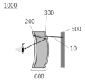
- FIG. 1 is a schematic diagram showing an example of a virtual image display device of the present invention.
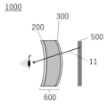
- FIG. 2 is a schematic diagram showing an example of the virtual image display device of the present invention.
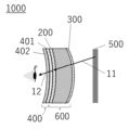
- FIG. 3 is a schematic diagram showing an example of the virtual image display device of the present invention.
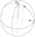
- FIG. 4 is a Poincare sphere diagram showing the change in the polarization state of a light ray passing through a reflective circular polarizer in the virtual image display device of the present invention.
- FIG. 5 is a Poincare sphere diagram showing the change in the polarization state of a light ray passing through a reflective circular polarizer in the virtual image display device of the present invention.
- FIG. 1 is a schematic diagram showing an example of a virtual image display device of the present invention.
- FIG. 2 is a schematic diagram showing an example of the virtual image display device of the present invention.
- FIG. 3 is a schematic diagram showing an example of the virtual image display device of the present invention.
- FIG. 4 is a Poincare
- FIG. 6 is a Poincare sphere diagram showing the change in the polarization state of a light ray passing through a reflective circular polarizer in the virtual image display device of the present invention.
- FIG. 7 is a Poincare sphere diagram showing the change in the polarization state of a light ray passing through a reflective circular polarizer in the virtual image display device of the present invention.
- orthogonal does not mean that the angle between two axes is strictly 90°, but rather 90° ⁇ 10°, preferably 90° ⁇ 5°.
- parallel does not mean that the angle between two axes is strictly 0°, but rather 0° ⁇ 10°, preferably 0° ⁇ 5°.
- 45° does not mean that the angle between two axes is strictly 45°, but rather means 45° ⁇ 10°, and preferably 45° ⁇ 5°.
- absorption axis refers to the polarization direction in which absorbance is maximum in the plane when linearly polarized light is incident.
- reflection axis refers to the polarization direction in which reflectance is maximum in the plane when linearly polarized light is incident.
- transmission axis refers to the direction in the plane that is perpendicular to the absorption axis or reflection axis.
- slow axis refers to the direction in the plane where the refractive index is maximum.
- Frest axis refers to the direction in the plane where the refractive index is minimum, and is the direction perpendicular to the slow axis.
- the phase difference means the in-plane retardation and is expressed as Re( ⁇ ), where Re( ⁇ ) represents the in-plane retardation at a wavelength ⁇ , and unless otherwise specified, the wavelength ⁇ is 550 nm.
- the retardation in the thickness direction at a wavelength ⁇ is referred to as Rth( ⁇ ) in this specification.
- the wavelength ⁇ is 550 nm.
- Re( ⁇ ) and Rth( ⁇ ) can be values measured at a wavelength ⁇ using an AxoScan OPMF-1 (manufactured by Optosciences Inc.).
- the virtual image display device of the present invention includes at least an image display device and a folding optical system including a reflective circular polarizer.
- the reflective circular polarizer further includes a cholesteric liquid crystal layer, the liquid crystal compound of which has a degree of orientation of 0.5 or more on the surface facing the image display device, and the director orientation of the liquid crystal compound within the effective area has a variation of 30° or less.
- FIG. 1 is a diagram conceptually showing an example of a virtual image display device of the present invention.
- 1 includes an image display device 500 and a folding optical system 600.
- the folding optical system 600 includes a reflective circular polarizer 200.
- the folding optical system 600 of the illustrated example includes a half mirror 300.
- the reflective circular polarizer 200 includes a cholesteric liquid crystal layer.
- the reflective circular polarizer 200 i.e., the cholesteric liquid crystal layer, for example, reflects right-handed circularly polarized light and transmits left-handed circularly polarized light.
- the cholesteric liquid crystal layer has a degree of orientation of the liquid crystal compound of 0.5 or more on the surface facing the image display device 500, and the variation in director orientation of the liquid crystal compound within the effective area is 30° or less.
- the light beam 10 (image) emitted by the image display device 500 is circularly polarized light.
- the image display device 500 emits right-handed circularly polarized light, for example.
- the image display device 500 has an image display element (display panel), a retardation layer ( ⁇ /4 wavelength plate), a linear polarizer, and a retardation layer ( ⁇ /4 wavelength plate) in this order.
- light (unpolarized) emitted from the image display element passes through the retardation layer, becomes linearly polarized by the linear polarizer, is converted to right-handed circularly polarized light by the retardation layer, and is emitted as light ray 10.
- the retardation layer immediately downstream of the image display element, together with the linear polarizer constitutes an anti-reflection film of the image display element.
- a portion of the light 10 (right-handed circularly polarized light) emitted from the image display device 500 passes through the half mirror 300 and then enters the reflective circular polarizer 200 .
- the reflective circular polarizer 200 has a cholesteric liquid crystal layer that selectively reflects right-handed circularly polarized light. Therefore, the right-handed circularly polarized light 10 incident on the reflective circular polarizer 200 is reflected by the reflective circular polarizer 200, the optical path is folded back, and the light is incident on the half mirror 300 again, where a part of the light is reflected by the half mirror 300. During this reflection, the light ray 10 is converted into left-handed circularly polarized light and enters the reflective circular polarizer 200 again.
- the reflective circular polarizer 200 is a cholesteric liquid crystal layer that selectively reflects right-handed circularly polarized light, and the light ray 10 has been converted into left-handed circularly polarized light. Therefore, the light ray 10 passes through the reflective circular polarizer 200. In this manner, a portion of the light beam 10 is folded back within the folding optical system 600 .
- the folding optical system 600 may refract the light ray 10 due to its shape, thereby generating lens power. Due to these effects, the light beam 10 emitted from the image display device 500 is substantially parallelized and reaches the user's eye, allowing the user to view the image displayed on the image display device as a virtual image.
- the reflective circular polarizer 200 reflects right-handed circularly polarized light and transmits left-handed circularly polarized light, but the present invention is not limited to this. That is, the reflective circular polarizer 200 may reflect left-handed circularly polarized light and transmit right-handed circularly polarized light. In this case, an image display device that emits left-handed circularly polarized light may be used, and the effect of the present invention does not lose generality.
- the above points also apply to the following explanations.
- a part of the light ray 10 emitted from the image display device 500 passes through the half mirror 300 , enters the reflective circular polarizer 200 , and is reflected by the reflective circular polarizer 200 .
- a part of light ray 10 emitted from image display device 500 is not reflected by reflective circular polarizer 200 after transmitting through half mirror 300, and is transmitted through reflective circular polarizer 200.
- this part of light ray 10 is referred to as light ray 11.
- Such light ray 11 is not substantially parallelized and reaches the user's eye via an optical path length different from that of light ray 10, and is therefore viewed as an image different from the virtual image viewed by the user, i.e., as a ghost.
- the virtual image display device 1000 of the present invention has an absorptive circular polarizer 400 in a preferred embodiment.
- the light beam 10 emitted by the image display device 500 is right-handed circularly polarized light.
- the light beam 11 that is unnecessarily transmitted through the reflective circular polarizer 200 when it is first incident on the reflective circular polarizer 200 is mostly right-handed circularly polarized light. Therefore, as conceptually shown in Fig.
- ghosts can be significantly reduced by laminating an absorptive circular polarizer 400 that absorbs right-handed circularly polarized light on the viewing side (user side) of the reflective circular polarizer 200.
- the absorptive circular polarizer 400 can be produced by laminating a ⁇ /4 wave plate ( ⁇ /4 retardation layer) 401 and an absorptive linear polarizer 402.
- the absorptive circular polarizer 400 transmits left-handed circularly polarized light, it has almost no effect on the display quality of the virtual image viewed by the user.
- the light ray 11 may be partially converted into left-handed circularly polarized light after passing through the reflective circular polarizer 200.
- the light ray that has been converted from the right-handed circularly polarized light 11 into the left-handed circularly polarized light is referred to as light ray 12 in order to distinguish it from the light ray 11 that is mainly right-handed circularly polarized light.
- this variation in the amount of light beam 12 is the cause of variation in the size of ghosts in a virtual image display device using a folding optical system.
- the light ray 12 Since the light ray 12 is left-handed circularly polarized light, it cannot be absorbed by the absorptive circular polarizer 400, which absorbs right-handed circularly polarized light. Therefore, it has been difficult to suppress the variation in ghost caused by the light ray 12 (left-handed circularly polarized light) which has a large variation in the amount of light.
- FIG. 4 conceptually illustrates, on the Poincare sphere, the change in polarization state of a light ray 11 that is incident on a reflective circular polarizer 200 and that is transmitted through the reflective circular polarizer 200 .
- Light ray 11 is right-handed circularly polarized when it enters reflective circular polarizer 200. Therefore, on the Poincaré sphere, it is represented at point S3 (the apex of the S3 axis).
- the reflective circular polarizer 200 selectively reflects right-handed circularly polarized light.
- the amount of transmitted light decreases.
- the distance from the center of the Poincaré sphere represents the amount of light. That is, in this specification, the decrease in the amount of transmitted light is described as the locus representing the change in the polarization state on the Poincaré sphere drawing a spiral near the S3 axis and approaching the center of the Poincaré sphere, as shown in FIG.
- FIG. 5 is a diagram of the Poincaré sphere in FIG. 4 as viewed from the direction of point S3 (S3 axis).
- S3 axis point S3
- the locus representing the change in the polarization state describes a spiral that is biased overall toward the first quadrant.
- the first quadrant is the quadrant formed by the S1 axis and the S2 axis.
- the director direction of the liquid crystal compound in the cholesteric liquid crystal layer can be in various directions, so the bias in the polarization state on the Poincaré sphere is not constant, which is presumably the cause of the variation in the size of the ghost.
- the light ray 10 emitted from the image display device 500 is not circularly polarized light in the strict sense, but is generally elliptically polarized light.
- the polarization state of the light ray 11 immediately before it enters the reflective circular polarizer 200 is represented on the Poincaré sphere, it will be represented at a position slightly away from the S3 axis (point S3), as shown by point A in Figures 6 and 7. As shown in Fig.
- ghosting can be reduced by adjusting the deviation of the locus of the change in the polarization state caused by the cholesteric liquid crystal layer in accordance with the polarization state of the light beam 10.
- ghosting can be reduced by adjusting the polarization state of the light beam 10 in accordance with the deviation of the locus of the change in the polarization state caused by the cholesteric liquid crystal layer.
- the direction of deviation of the locus of the change in the polarization state caused by the cholesteric liquid crystal layer is largely determined by the orientation of the director of the liquid crystal compound on the light incident surface side of the cholesteric liquid crystal layer. Therefore, ghosts can be reduced by adjusting the orientation of the director of the liquid crystal compound on the light incident surface side of the cholesteric liquid crystal layer in accordance with the polarization state of the light beam 10.
- the variation in the size of ghosts has two specific meanings.
- the first variation in the size of the ghost is the variation in the size of the ghost for each individual cholesteric liquid crystal layer (reflective circular polarizer), i.e., virtual image display device.
- the variation in the size of the ghost is due to individual differences between multiple components and devices.
- the second type of variation in ghost size is the variation in size of the ghost within the plane of one cholesteric liquid crystal layer (reflective circular polarizer), i.e., in the image displayed by one virtual image display device.
- the variation in size of the ghost is, for example, the variation in the displayed virtual image such that the ghost is small in the vertical center and large at the top and bottom.
- ⁇ Virtual image display device of the present invention Based on the above assumption, the inventors estimated that by controlling the orientation of the director of the liquid crystal compound on the light incident side of the cholesteric liquid crystal layer to a constant orientation, it is possible to reduce the variation in the size of ghosts in a virtual image display device, and thus arrived at the present invention. That is, as described above, the generation of left-handed circularly polarized light that causes ghosts is due to a change in the polarization state of light ray 11, which is right-handed circularly polarized light that passes through the cholesteric liquid crystal layer.
- the direction in which the locus representing the change in polarization state first moves on the Poincaré sphere is determined by the orientation of the director of the liquid crystal compound on the light-incident surface side of the cholesteric liquid crystal layer. Therefore, the direction of polarization in FIG. 5 is roughly determined by the orientation of the director of the liquid crystal compound on the light-incident surface side of the cholesteric liquid crystal layer. Variations in the orientation of this director cause variations in the size of ghosts.
- the change in the polarization state of the circularly polarized (elliptically polarized) light passing through the reflective circular polarizer 200 can be made uniform, thereby reducing the variation in ghosts.
- the virtual image display device of the present invention has at least an image display device and a folding optical system including a reflective circular polarizer, and the reflective circular polarizer includes a cholesteric liquid crystal layer, and the cholesteric liquid crystal layer has a degree of orientation of the liquid crystal compound of 0.5 or more on the surface facing the image display device, i.e., the surface on which light ray 10 (light ray 11) is incident, and the variation in director orientation of the liquid crystal compound within the effective area is 30° or less.
- the virtual image display device of the present invention has such a configuration, and thus can reduce the variation in size of ghosts in the virtual image display device.
- the effective area refers to an in-plane area of a reflective circular polarizer incorporated in a virtual image display device, through which light from the image display device passes when a user views a displayed virtual image.
- the orientation degree of the liquid crystal compound in the cholesteric liquid crystal layer on the surface facing the image display device is less than 0.5, then it becomes difficult to sufficiently reduce the variation in ghosts, and the circularly polarized light that should be reflected (for example, right-handed circularly polarized light) cannot be sufficiently reflected, resulting in inconveniences such as an increase in ghosts.
- the degree of orientation of the liquid crystal compound in the cholesteric liquid crystal layer on the surface on the image display device side is preferably 0.6 or more, and more preferably 0.65 or more. In the present invention, the higher the degree of orientation of the liquid crystal compound in the cholesteric liquid crystal layer on the surface on the image display device side, the more preferable, with the upper limit being 1 being the most preferable.
- the variation in director orientation of the liquid crystal compound within the effective region of the cholesteric liquid crystal layer on the surface on the image display device side exceeds 30°, the variation in ghosts cannot be reduced sufficiently.
- the variation in director orientation of the liquid crystal compound within the effective region of the cholesteric liquid crystal layer on the surface on the image display device side is preferably 10° or less, more preferably 5° or less.
- the smaller the variation in the director orientation of the liquid crystal compound within the effective region of the cholesteric liquid crystal layer on the surface on the image display device side the more preferable, and 0° is the most preferable.
- the orientation of the polarization axis of the elliptically polarized light at a wavelength of 550 nm emitted by the image display device and the orientation of the director of the liquid crystal compound on the surface of the cholesteric liquid crystal layer on the image display device side preferably form an angle of 45 to 90°, and more preferably form an angle of 55 to 80°.
- the orientation of the polarization axis of the elliptically polarized light at a wavelength of 550 nm emitted by the image display device and the orientation of the director of the liquid crystal compound on the surface of the cholesteric liquid crystal layer on the image display device side preferably form an angle of 0 to 45°, more preferably an angle of 10 to 35°.
- the position on the Poincaré sphere of the elliptically polarized light is a position that cancels the bias in the polarization state caused by the cholesteric liquid crystal layer, thereby minimizing ghosts.
- the ellipticity of the elliptically polarized light emitted by the image display device is preferably 0.8 to 0.99 on average at wavelengths of 450 to 650 nm. When the ellipticity is within this range, ghosts can be further reduced, which is preferable.
- the average ellipticity is more preferably 0.85 to 0.98, and even more preferably 0.93 to 0.98.
- the direction of the elliptical axis of elliptically polarized light refers to the direction of the major axis of the ellipse in the elliptical orbit traced by the change in the electric field in the elliptically polarized light
- the ellipticity refers to the ratio of the lengths of the major axis and the minor axis in the elliptical orbit.
- the elliptical axis orientation and ellipticity of the elliptically polarized light emitted by the image display device can be obtained, for example, by peeling the circular polarizer from the surface of the image display device and measuring it at a wavelength of 550 nm using an AxoScan OPMF-1 (manufactured by OptoScience Corporation).
- a reflective circular polarizer is a polarizer that transmits right-handed or left-handed circularly polarized light and reflects circularly polarized light that has the opposite rotation direction to the transmitted circularly polarized light.
- the reflective circular polarizer included in the virtual image display device of the present invention has a cholesteric liquid crystal layer.
- the cholesteric liquid crystal layer is a liquid crystal phase formed by fixing a cholesterically oriented liquid crystal phase (cholesteric liquid crystal phase).
- a cholesteric liquid crystal layer has a helical structure in which liquid crystal compounds are spirally rotated and stacked, and the liquid crystal compounds are stacked in a spiral shape, with one helical period (helical period (helical pitch)) being one rotation (360° rotation) of the liquid crystal compounds.
- the cholesteric liquid crystal layer has a structure in which the helically rotating liquid crystal compounds are stacked in multiple periods.
- a cholesteric liquid crystal layer reflects right-handed or left-handed circularly polarized light in a specific wavelength range and transmits other light depending on the length of the helical period and the sense of rotation of the helix by the liquid crystal compound.
- the reflective circular polarizer may have multiple cholesteric liquid crystal layers, for example a cholesteric liquid crystal layer having a central wavelength that selectively reflects red light, a cholesteric liquid crystal layer having a central wavelength that selectively reflects green light, and a cholesteric liquid crystal layer having a central wavelength that selectively reflects blue light.
- the reflective circular polarizer may also have a support and an alignment film for aligning the liquid crystal compound in the cholesteric liquid crystal layer.
- a reflective circular polarizer included in a folding optical system includes a cholesteric liquid crystal layer, in which the orientation degree of the liquid crystal compound on the surface facing the image display device is 0.5 or more, and the variation of the director orientation of the liquid crystal compound within the effective area is 30° or less.
- the above-mentioned degree of orientation and variation in director direction on the surface of the cholesteric liquid crystal layer facing the image display device can be achieved by performing an orientation treatment when forming the cholesteric liquid crystal layer so that the orientation direction of the liquid crystal compound is aligned in one direction.
- the alignment treatment can be carried out, for example, by applying a photo-alignment film to a support, irradiating the photo-alignment film with polarized ultraviolet light or the like, applying a liquid crystal composition containing a liquid crystal compound, aligning the liquid crystal compound in a cholesteric liquid crystal phase state, and then curing the liquid crystal compound to form a cholesteric liquid crystal layer in which the cholesteric liquid crystal phase is fixed.
- the direction of the director of the liquid crystal compound can be controlled by the direction of the polarization axis of the polarized light irradiated to the photo-alignment film.
- the alignment treatment can be carried out in the same manner by subjecting the support or the alignment film applied on the support to a rubbing treatment.
- the alignment treatment surface of the cholesteric liquid crystal layer thus formed is the image display device side, i.e., the incident side of light ray 10 (light ray 11). This makes it possible to make the degree of alignment of the liquid crystal compound on the image display device side surface of the cholesteric liquid crystal layer 0.5 or more and the variation in director orientation of the liquid crystal compound within the effective area 30° or less.
- the degree of orientation of the liquid crystal compound on the surface of the cholesteric liquid crystal layer and the direction of the director can be measured by SHG (Second Harmonic Generation) measurement or the like.
- the degree of orientation is an index representing the degree of local order of a liquid crystal compound, and is also called an order parameter.
- the degree of orientation may be determined by SHG measurement at five points within an effective area when the reflective circular polarizer is incorporated into a virtual image display device, and all of the five points should be 0.5 or more.
- the director orientation refers to the direction of the main axis of the liquid crystal compound.
- the variation in the director orientation of the liquid crystal compound in the effective area is the maximum value of the angle between the director orientations at different locations when SHG measurement is performed at five locations in the effective area when the reflective circular polarizer is incorporated into a virtual image display device to measure the local director orientations.
- the photo-alignment film is an alignment film that contains a photo-alignment material.
- the photo-alignment material contained in the photo-alignment film include those described in JP-A-2006-285197, JP-A-2007-76839, JP-A-2007-138138, JP-A-2007-94071, JP-A-2007-121721, JP-A-2007-140465, JP-A-2007-156439, and JP-A-2007-160144.
- Particularly preferred examples of the photoalignment material include azo compounds, photocrosslinkable polyimides,
- the photo-alignment film can be formed by applying a composition containing the photo-alignment material to form a coating film, irradiating the coating film with light, and imparting an alignment control force.
- the light irradiation is preferably performed by irradiating polarized light from a direction perpendicular to the surface of the coating film or a direction tilted from the perpendicular direction.
- the light irradiation may also be performed by irradiating non-polarized light from a direction tilted from the perpendicular direction to the surface of the coating film.
- the composition containing the photoalignment material may contain components other than the photoalignment material capable of forming a photoalignment film.
- the refractive index of the photo-alignment film can be adjusted by the type of photo-alignment material.
- the refractive index of the photo-alignment film can also be adjusted by other components that may be included together with the photo-alignment material.
- the photo-alignment film is a layer that has the ability to align liquid crystals.
- liquid crystal alignment ability is the ability to impart alignment to liquid crystal compounds.
- the cholesteric liquid crystal layer can be formed by fixing a cholesteric liquid crystal phase in a layer form.
- the structure in which the cholesteric liquid crystal phase is fixed may be any structure in which the orientation of the liquid crystal compound in the cholesteric liquid crystal phase is maintained, and typically, a structure in which a polymerizable liquid crystal compound is brought into a cholesteric liquid crystal phase orientation state, and then polymerized and hardened by ultraviolet light irradiation, heating, etc. to form a layer with no fluidity, and at the same time, changed to a state in which the orientation form is not changed by an external field or external force, is preferred.
- the polymerizable liquid crystal compound may be polymerized by a curing reaction and lose its liquid crystallinity.
- An example of a material used to form a cholesteric liquid crystal layer formed by fixing a cholesteric liquid crystal phase is a liquid crystal composition containing a liquid crystal compound, which is preferably a polymerizable liquid crystal compound.
- the liquid crystal composition used to form the cholesteric liquid crystal layer may further contain a surfactant and a chiral agent.
- the polymerizable liquid crystal compound may be a rod-shaped liquid crystal compound or a discotic liquid crystal compound.
- rod-shaped polymerizable liquid crystal compounds that form cholesteric liquid crystal phase include rod-shaped nematic liquid crystal compounds.As rod-shaped nematic liquid crystal compounds, azomethines, azoxys, cyanobiphenyls, cyanophenyl esters, benzoates, cyclohexane carboxylic acid phenyl esters, cyanophenylcyclohexanes, cyano-substituted phenylpyrimidines, alkoxy-substituted phenylpyrimidines, phenyldioxanes, tolanes, and alkenylcyclohexylbenzonitriles are preferably used.Not only low molecular weight liquid crystal compounds, but also high molecular weight liquid crystal compounds can be used.
- the polymerizable liquid crystal compound is obtained by introducing a polymerizable group into a liquid crystal compound.
- the polymerizable group include an unsaturated polymerizable group, an epoxy group, and an aziridinyl group, with an unsaturated polymerizable group being preferred, and an ethylenically unsaturated polymerizable group being more preferred.
- the polymerizable group can be introduced into the molecule of the liquid crystal compound by various methods.
- the number of polymerizable groups that the polymerizable liquid crystal compound has is preferably 1 to 6, more preferably 1 to 3. Examples of the polymerizable liquid crystal compounds are described in Makromol. Chem. , Vol. 190, p. 2255 (1989), Advanced Materials Vol. 5, p.
- polymerizable liquid crystal compounds that can be used include cyclic organopolysiloxane compounds having a cholesteric phase as disclosed in JP-A-57-165480.
- the aforementioned polymer liquid crystal compounds can include polymers in which mesogen groups exhibiting liquid crystallinity have been introduced into the main chain, side chain, or both the main chain and side chain, polymer cholesteric liquid crystals in which cholesteryl groups have been introduced into the side chain, liquid crystalline polymers as disclosed in JP-A-9-133810, and liquid crystalline polymers as disclosed in JP-A-11-293252.
- discotic liquid crystal compounds-- As the discotic liquid crystal compound, for example, those described in JP-A-2007-108732 and JP-A-2010-244038 can be preferably used.
- the reflective circular polarizer includes at least a cholesteric liquid crystal layer formed using a first liquid crystal compound consisting essentially of a rod-shaped liquid crystal compound, and a cholesteric liquid crystal layer formed using a second liquid crystal compound consisting essentially of a discotic liquid crystal compound.
- the above “consisting essentially of rod-shaped liquid crystal compounds” means that the liquid crystal compounds contained in the cholesteric liquid crystal layer are 95% by mass or more of rod-shaped liquid crystal compounds.
- the above “consisting essentially of discotic liquid crystal compounds” means that the liquid crystal compounds contained in the cholesteric liquid crystal layer are 95% by mass or more of discotic liquid crystal compounds.
- the amount of the polymerizable liquid crystal compound added to the liquid crystal composition is preferably 75 to 99.9% by mass, more preferably 80 to 99% by mass, and even more preferably 85 to 90% by mass, based on the solid content mass of the liquid crystal composition (mass excluding the solvent).
- the liquid crystal composition used in forming the cholesteric liquid crystal layer may contain a surfactant.
- the surfactant is preferably a compound that can function as an alignment control agent that contributes to the alignment of the cholesteric liquid crystal phase stably or quickly.
- examples of the surfactant include silicone surfactants and fluorine surfactants, and fluorine surfactants are preferred.
- the surfactant include the compounds described in paragraphs [0082] to [0090] of JP-A-2014-119605, the compounds described in paragraphs [0031] to [0034] of JP-A-2012-203237, the compounds exemplified in paragraphs [0092] and [0093] of JP-A-2005-099248, the compounds exemplified in paragraphs [0076] to [0078] and paragraphs [0082] to [0085] of JP-A-2002-129162, and fluorine (meth)acrylate polymers described in paragraphs [0018] to [0043] of JP-A-2007-272185, and the like.
- the surfactant may be used alone or in combination of two or more kinds.
- the fluorine-based surfactant the compounds described in paragraphs [0082] to [0090] of JP-A-2014-119605 are preferred.
- the amount of surfactant added in the liquid crystal composition is preferably 0.01 to 10% by mass, more preferably 0.01 to 5% by mass, and even more preferably 0.02 to 1% by mass, based on the total mass of the liquid crystal compound.
- Chiral agents have the function of inducing a helical structure in the cholesteric liquid crystal phase.
- Chiral agents can be selected according to the purpose, since the twist direction or helical period of the helical structure induced varies depending on the compound.
- the chiral agent is not particularly limited, and known compounds (for example, those described in Liquid Crystal Device Handbook, Chapter 3, Section 4-3, Chiral Agents for TN (twisted nematic) and STN (Super Twisted Nematic), p. 199, edited by the 142nd Committee of the Japan Society for the Promotion of Science, 1989), isosorbide, and isomannide derivatives can be used.
- the chiral agent generally contains an asymmetric carbon atom
- an axially asymmetric compound or a planarly asymmetric compound that does not contain an asymmetric carbon atom can also be used as the chiral agent.
- the axially asymmetric compound or the planarly asymmetric compound include binaphthyl, helicene, paracyclophane, and derivatives thereof.
- the chiral agent may have a polymerizable group.
- a polymer having a repeating unit derived from the polymerizable liquid crystal compound and a repeating unit derived from the chiral agent can be formed by a polymerization reaction between the polymerizable chiral agent and the polymerizable liquid crystal compound.
- the polymerizable group of the polymerizable chiral agent is preferably the same type of group as the polymerizable group of the polymerizable liquid crystal compound.
- the polymerizable group of the chiral agent is also preferably an unsaturated polymerizable group, an epoxy group, or an aziridinyl group, more preferably an unsaturated polymerizable group, and even more preferably an ethylenically unsaturated polymerizable group.
- the chiral agent may also be a liquid crystal compound.
- the chiral agent has a photoisomerizable group
- a pattern of a desired reflection wavelength corresponding to the emission wavelength can be formed by irradiating a photomask with actinic rays or the like after coating and alignment.
- the photoisomerizable group an isomerization site of a compound exhibiting photochromic properties, an azo group, an azoxy group, or a cinnamoyl group is preferable.
- Specific examples of the compound include those described in JP-A-2002-080478, JP-A-2002-080851, JP-A-2002-179668, JP-A-2002-179669, JP-A-2002-179670, JP-A-2002-179681, JP-A-2002-179682, JP-A-2002-338575, JP-A-2002-338668, JP-A-2003-313189, and JP-A-2003-313292.
- the content of the chiral agent in the liquid crystal composition is preferably 0.01 to 200 mol %, more preferably 1 to 30 mol %, based on the molar content of the liquid crystal compound.
- the liquid crystal composition contains a polymerizable compound, it preferably contains a polymerization initiator.
- the polymerization initiator used is preferably a photopolymerization initiator capable of initiating the polymerization reaction by ultraviolet irradiation.
- the photopolymerization initiator include ⁇ -carbonyl compounds (described in U.S. Pat. Nos. 2,367,661 and 2,367,670), acyloin ethers (described in U.S. Pat. No. 2,448,828), ⁇ -hydrocarbon-substituted aromatic acyloin compounds (described in U.S.
- the content of the photopolymerization initiator in the liquid crystal composition is preferably 0.1 to 20% by mass, and more preferably 0.5 to 12% by mass, based on the content of the liquid crystal compound.
- the liquid crystal composition may contain a crosslinking agent in order to improve the film strength and durability after curing.
- a crosslinking agent those which are cured by ultraviolet light, heat, moisture, etc. can be suitably used.
- the crosslinking agent is not particularly limited and can be appropriately selected according to the purpose.
- crosslinking agent examples include polyfunctional acrylate compounds such as trimethylolpropane tri(meth)acrylate and pentaerythritol tri(meth)acrylate; epoxy compounds such as glycidyl (meth)acrylate and ethylene glycol diglycidyl ether; aziridine compounds such as 2,2-bishydroxymethylbutanol-tris[3-(1-aziridinyl)propionate] and 4,4-bis(ethyleneiminocarbonylamino)diphenylmethane; isocyanate compounds such as hexamethylene diisocyanate and biuret type isocyanate; polyoxazoline compounds having an oxazoline group in the side chain; and alkoxysilane compounds such as vinyltrimethoxysilane and N-(2-aminoethyl)3-aminopropyltrimethoxysilane.
- polyfunctional acrylate compounds such as trimethylolpropane tri(meth)acrylate and pent
- a known catalyst can be used depending on the reactivity of the crosslinking agent, and in addition to improving the film strength and durability, productivity can be improved. These may be used alone or in combination of two or more.
- the content of the crosslinking agent is preferably 3 to 20% by mass, more preferably 5 to 15% by mass, based on the solid content by mass of the liquid crystal composition. When the content of the crosslinking agent is within the above range, the effect of improving the crosslinking density is easily obtained, and the stability of the cholesteric liquid crystal phase is further improved.
- a polymerization inhibitor an antioxidant, an ultraviolet absorber, a light stabilizer, a colorant, metal oxide fine particles, etc. may be added to the liquid crystal composition within a range that does not deteriorate the optical performance, etc.
- the liquid crystal composition is preferably used in the form of a liquid when forming a cholesteric liquid crystal layer.
- the liquid crystal composition may contain a solvent.
- the solvent is not limited and can be appropriately selected depending on the purpose, but an organic solvent is preferable.
- the organic solvent is not limited and can be appropriately selected according to the purpose, and examples thereof include ketones, alkyl halides, amides, sulfoxides, heterocyclic compounds, hydrocarbons, esters, and ethers. These may be used alone or in combination of two or more. Among these, ketones are preferred when considering the burden on the environment.
- a liquid crystal composition When forming a cholesteric liquid crystal layer, it is preferable to apply a liquid crystal composition to the surface on which the cholesteric liquid crystal layer is to be formed, align the liquid crystal compound in a cholesteric liquid crystal phase state, and then harden the liquid crystal compound to form a cholesteric liquid crystal layer. That is, when forming a cholesteric liquid crystal layer on an alignment film, it is preferable to apply a liquid crystal composition to the alignment film, align the liquid crystal compound in a cholesteric liquid crystal phase state, and then harden the liquid crystal compound to form a cholesteric liquid crystal layer in which the cholesteric liquid crystal phase is fixed.
- a liquid crystal composition can be applied onto an already formed cholesteric liquid crystal layer, the liquid crystal compound is oriented in a cholesteric liquid crystal phase state, and then the liquid crystal compound is hardened to form a second cholesteric liquid crystal layer.
- the liquid crystal composition can be applied by any known method capable of uniformly applying a liquid to a sheet-like material, such as printing methods including ink-jet printing and scroll printing, as well as spin coating, bar coating and spray coating.
- the applied liquid crystal composition is dried and/or heated as necessary, and then cured to form a cholesteric liquid crystal layer.
- the liquid crystal compounds in the liquid crystal composition are aligned in a cholesteric liquid crystal phase.
- the heating temperature is preferably 200°C or less, and more preferably 130°C or less.
- the aligned liquid crystal compound is further polymerized as necessary.
- the polymerization may be either thermal polymerization or photopolymerization by light irradiation, but photopolymerization is preferred.
- ultraviolet light is preferably used.
- the irradiation energy is preferably 20 mJ/cm 2 to 50 J/cm 2 , more preferably 50 to 1500 mJ/cm 2.
- light irradiation may be performed under heating conditions or in a nitrogen atmosphere.
- the wavelength of the ultraviolet light to be irradiated is preferably 250 to 430 nm.
- the thickness of the cholesteric liquid crystal layer there is no limit to the thickness of the cholesteric liquid crystal layer, and the thickness that provides the required light reflectance can be set appropriately depending on the light reflectance required for the cholesteric liquid crystal layer and the material from which the cholesteric liquid crystal layer is formed.
- the virtual image display device of the present invention may have a ⁇ /4 wave plate 401 and an absorptive linear polarizer 402 in this order on the viewing side surface of the reflective circular polarizer.
- Combining the ⁇ /4 wave plate 401 and the absorbing linear polarizer 402 can function as the absorbing circular polarizer 400.
- the reflective circular polarizer reflects right-handed circularly polarized light
- the right-handed circularly polarized light that is not completely reflected by the reflective circular polarizer is converted to linearly polarized light by the ⁇ /4 wave plate and then absorbed by the absorbing linear polarizer, which is preferable because this reduces ghosting.
- the material constituting the ⁇ /4 wave plate is not particularly limited, and examples thereof include liquid crystal compounds and polymers.
- the liquid crystal compound can form a retardation layer by orienting a liquid crystal material to exhibit refractive index anisotropy.
- the polymer can form a ⁇ /4 wave plate by exhibiting refractive index anisotropy by stretching a polymer film obtained by casting and coating, etc.
- the ⁇ /4 wave plate is preferably a layer formed using a liquid crystal compound, and more preferably a layer formed using a liquid crystal compound having a polymerizable group.
- the liquid crystal compound used in the ⁇ /4 wave plate is preferably a liquid crystal compound having a polymerizable group.
- the liquid crystal compound may be a liquid crystal compound that exhibits either forward or reverse wavelength dispersion.
- a liquid crystal compound that exhibits reverse wavelength dispersion is preferred, and a liquid crystal compound that has two or more polymerizable groups and exhibits reverse wavelength dispersion is more preferred.
- a liquid crystal compound exhibiting reverse wavelength dispersion refers to a compound that satisfies the relationship between the following formulas (A) and (B) when the in-plane retardation (Re) value at a specific wavelength (visible light range) of an optically anisotropic layer produced using this compound is measured.
- the ⁇ /4 wave plate is preferably a layer formed using a liquid crystal compound having a polymerizable group, and more preferably a layer in which the orientation state of the liquid crystal compound having a polymerizable group is fixed.
- the orientation state that a liquid crystal compound having a polymerizable group can take is not particularly limited, and examples thereof include homogeneous orientation, homeotropic orientation, twisted orientation, cholesteric orientation, hybrid orientation, and tilted orientation.
- the hybrid orientation is an orientation in which the tilt angle of the liquid crystal compound changes continuously from one surface to the other surface.
- the tilt orientation is an orientation in which the tilt angle of the liquid crystal compound is constant from one surface to the other surface.
- the twisted orientation represents an orientation state in which the liquid crystal compound is twisted around the thickness direction as the axis of rotation, and when the liquid crystal compound is twisted and has a predetermined tilt angle (tilt angle greater than 0°), it corresponds to a twisted hybrid orientation.
- the twisted orientation corresponds to an aspect in which the twist angle of the liquid crystal compound is less than 360°
- the above-mentioned cholesteric orientation corresponds to an aspect in which the twist angle of the liquid crystal compound is 360° or more.
- a ⁇ /4 waveplate formed using a liquid crystal compound may have multiple regions along the thickness direction in which the liquid crystal compound has different orientation states.
- a ⁇ /4 waveplate may have a region along the thickness direction in which the liquid crystal compound is fixed in a homogeneously oriented state and a region in which the liquid crystal compound is fixed in a twisted oriented state.
- the thickness of the ⁇ /4 wave plate is not particularly limited, but is preferably 0.1 to 10.0 ⁇ m, and more preferably 0.5 to 5.0 ⁇ m.
- the configuration of the wideband ⁇ / 4 wave plate include those configured with a single-layer retardation layer, such as a retardation layer using a liquid crystal compound exhibiting reverse wavelength dispersion as disclosed in WO 2019 / 160016, JP 2020-173460, and WO 2021 / 157694, and a ⁇ / 4 wave plate having a plurality of regions in which the orientation state of the liquid crystal compound disclosed in WO 2022 / 030308 and JP 2022-184691 is different along the thickness direction.
- a single-layer retardation layer such as a retardation layer using a liquid crystal compound exhibiting reverse wavelength dispersion as disclosed in WO 2019 / 160016, JP 2020-173460, and WO 2021 / 157694
- a ⁇ / 4 wave plate having a plurality of regions in which the orientation state of the liquid crystal compound disclosed in WO 2022 / 030308 and JP 2022-184691 is different along the thickness direction.
- examples of a laminate of two or more retardation layers include a combination of a ⁇ /4 retardation layer and a ⁇ /2 retardation layer disclosed in JP-A-2001-108825, JP-A-2001-91741, and WO 2013/137464, and a combination of a retardation layer having a twisted orientation and another retardation layer disclosed in JP-A-2001-21720, JP-A-2014-209219, and WO 2022/255105.
- the ⁇ /4 wave plate may further include other retardation layers, such as a positive C plate and a negative C plate, in order to compensate for a change in retardation caused by light incident in an oblique direction.
- An absorptive linear polarizer refers to a linear polarizer that absorbs linearly polarized light in the absorption axis direction of incident light and transmits linearly polarized light in the transmission axis direction.
- the absorptive linear polarizer a known absorptive linear polarizer can be used.
- it may be a polarizer in which a dichroic substance is dyed onto polyvinyl alcohol or other polymer resin and then oriented by stretching, or it may be a polarizer in which a dichroic substance is oriented by utilizing the orientation of a liquid crystal compound.
- the thickness of the absorbing linear polarizer is preferably 10 ⁇ m or less, more preferably 7 ⁇ m or less, and even more preferably 5 ⁇ m or less. When the absorbing linear polarizer is thin, it is possible to prevent cracks, breakage, and the like from occurring when the absorbing linear polarizer is stretched or molded.
- the single plate transmittance of the absorptive linear polarizer is preferably 40% or more, and more preferably 42% or more.
- the degree of polarization is preferably 90% or more, more preferably 95% or more, and even more preferably 99% or more.
- the single plate transmittance and degree of polarization of the absorptive linear polarizer are measured using an automatic polarizing film measuring device: VAP-7070 (manufactured by JASCO Corporation).
- the angle between the transmission axis of the absorptive linear polarizer and the slow axis of the ⁇ /4 wave plate is preferably 45 ⁇ 10°, more preferably 45 ⁇ 5°, and even more preferably 45 ⁇ 3°.
- the absorptive linear polarizer is preferably a light absorbing anisotropic layer containing a liquid crystal compound and a dichroic substance.
- a linear polarizer containing a liquid crystal compound and a dichroic substance is preferable because it can be thinned and is unlikely to crack or break even when stretched and molded.
- the thickness of the optically absorptive anisotropic layer is not particularly limited, but from the viewpoint of achieving a thin film, it is preferably from 0.1 to 8 ⁇ m, and more preferably from 0.3 to 5 ⁇ m.
- a linear polarizer containing a liquid crystal compound and a dichroic substance can be produced, for example, by referring to JP-A-2020-023153, etc.
- the light absorption anisotropic layer preferably has an orientation degree of the dichroic substance of 0.95 or more, more preferably 0.97 or more.
- the liquid crystal compound contained in the composition for forming an optically absorptive anisotropic layer for forming the optically absorptive anisotropic layer is preferably a liquid crystal compound that does not exhibit dichroism in the visible range.
- the liquid crystal compound either a low molecular weight liquid crystal compound or a polymeric liquid crystal compound can be used.
- low molecular weight liquid crystal compound refers to a liquid crystal compound that does not have a repeating unit in its chemical structure.
- polymeric liquid crystal compound refers to a liquid crystal compound that has a repeating unit in its chemical structure.
- polymer liquid crystal compound examples include the thermotropic liquid crystal polymer described in JP 2011-237513 A.
- the polymer liquid crystal compound preferably has a crosslinkable group (e.g., an acryloyl group or a methacryloyl group) at the end.
- the liquid crystal compounds may be used alone or in combination of two or more. It is also preferable to use a high molecular weight liquid crystal compound and a low molecular weight liquid crystal compound in combination.
- the content of the liquid crystal compound is preferably 25 to 2000 parts by mass, more preferably 33 to 1000 parts by mass, and even more preferably 50 to 500 parts by mass, per 100 parts by mass of the dichroic substance in the composition.
- the dichroic substance contained in the composition for forming an optically absorptive anisotropic layer for forming an optically absorptive anisotropic layer is not particularly limited, and examples thereof include visible light absorbing substances (dichroic dyes), ultraviolet absorbing substances, infrared absorbing substances, nonlinear optical substances, carbon nanotubes, and the like. Any conventionally known dichroic substance (dichroic dye) can be used. In the absorptive linear polarizer, two or more dichroic substances may be used in combination.
- the reflective circular polarizer, the ⁇ /4 wave plate, and the absorptive linear polarizer used in the virtual image display device of the present invention may include a support and/or an alignment layer.
- the reflective circular polarizer, the ⁇ /4 wave plate, and the absorptive linear polarizer used in the virtual image display device of the present invention may have a support and/or an alignment layer during production, and the support or even the alignment layer may be peeled off in the end. That is, the support and the alignment layer may be a temporary support that is finally peeled off and removed. By peeling off and removing the temporary support, the virtual image display device can be made thinner, and further, the adverse effect of the phase difference of the temporary support on the polarization degree of transmitted light can be eliminated, which is preferable.
- the type of the support is not particularly limited, but is preferably transparent to visible light.
- the support may be, for example, a film (sheet-like material) made of triacetyl cellulose, polyethylene terephthalate film, polyolefin such as polyethylene, polypropylene, or norbornene polymer, cyclic olefin resin, polyvinyl alcohol, polyethylene terephthalate, acrylic resin such as polymethacrylic acid ester and polyacrylic acid ester, polyethylene naphthalate, polycarbonate, polysulfone, polyether sulfone, polyether ketone, polyphenylene sulfide, or polyphenylene oxide.
- Commercially available products may also be used as the support.
- Technoloy S001G Technoloy S014G
- Technoloy S000 Technoloy C001
- Technoloy C000 Technoloy C000
- Lumirror U-type Lumirror FX10
- Lumirror SF20 Toray Industries, Inc.
- HK-53A Higashiyama Films Co., Ltd.
- Teflex FT3 Teijin DuPont Films Co., Ltd.
- S-Cina and SCA40 Sekisui Chemical Co., Ltd.
- Zeonor Film Optes Co., Ltd.
- Arton Film JSR Corporation
- the reflective circular polarizer, ⁇ /4 wave plate, and absorptive linear polarizer used in the virtual image display device of the present invention are preferably transparent to near-infrared light.
- the virtual image display device of the present invention may have other functional layers in addition to the reflective circular polarizer, the ⁇ /4 wave plate, and the absorptive linear polarizer. Suitable examples of these functional layers include a positive C plate and an anti-reflection layer, and the virtual image display device of the present invention preferably includes these.
- the reflective circular polarizer, the ⁇ /4 wave plate, and the absorptive linear polarizer used in the virtual image display device of the present invention are preferably attached to the surface of a lens to form a folding optical system.
- a half mirror is formed on the surface of the lens opposite to the surface to which the reflective circular polarizer is attached.
- the reflective circular polarizer, the ⁇ /4 wave plate, and the absorptive linear polarizer may be molded into a curved shape to match the surface shape of the lens. It is preferable that these members are molded into a curved shape to match the surface shape of the lens in order to reduce image distortion and aberration.
- the method for molding a reflective circular polarizer, a ⁇ /4 wavelength plate, and an absorptive linear polarizer onto a curved surface there are no limitations on the method for molding a reflective circular polarizer, a ⁇ /4 wavelength plate, and an absorptive linear polarizer onto a curved surface, and various known methods can be used depending on the forming material and layer structure of the reflective circular polarizer, etc.
- the lens there is no limitation on the lens, and various known lenses can be used.
- the lens include a convex lens and a concave lens.
- the convex lens include a biconvex lens, a plano-convex lens, and a convex meniscus lens.
- the concave lens include a biconcave lens, a plano-concave lens, and a concave meniscus lens.
- the lens may be made of a material that is transparent to visible light, such as glass, crystal, or plastic. Since birefringence of a lens causes rainbow unevenness and light leakage, the smaller the birefringence, the more preferable, and a material with substantially zero birefringence is more preferable.
- Image display device In the virtual image display device of the present invention, there is no limitation on the image display device (image display element (display panel)), and various known image display devices used for virtual image displays and the like can be used. Examples of image display devices include liquid crystal displays (LCDs (Liquid Crystal Displays)), organic electroluminescence displays (OLEDs (Organic Light Emitting Diodes)), CRTs (cathode-ray tubes), electronic paper, LED (Light Emitting Diode) displays, micro LED displays, DLPs (Digital Light Processing), and MEMS (Micro-Electro-Mechanical Systems) type displays.
- LCDs Liquid Crystal Displays
- OLEDs Organic Light Emitting Diodes
- CRTs cathode-ray tubes
- electronic paper LED (Light Emitting Diode) displays
- micro LED displays micro LED displays
- DLPs Digital Light Processing
- MEMS Micro-Electro-Mechanical Systems
- the image display device may have optical elements such as a retardation layer ( ⁇ /4 wave plate) and a linear polarizer as described above, if necessary.
- the image display element is an element that outputs linearly polarized light such as a liquid crystal display, the linear polarizer is not necessary.
- the numerical values are mass %.
- R is a group bonded via an oxygen atom.
- the average molar absorption coefficient of the above rod-shaped liquid crystal compound in the wavelength range of 300 to 400 nm was 140/mol cm.
- Chiral agent A is a chiral agent whose helical twisting power (HTP) is reduced by light.
- a PET film (A4265, manufactured by Toyobo Co., Ltd.) having a thickness of 100 ⁇ m was prepared, and the PET surface on the side on which the adhesive layer was not formed was subjected to a rubbing treatment.
- the prepared reflective layer coating solution R-1 was applied with a wire bar coater, and then dried at 110°C for 72 seconds.
- the coating was cured by irradiating light from a metal halide lamp at 100°C with an illuminance of 80 mW/ cm2 and an exposure dose of 500 mJ/ cm2 in a low-oxygen atmosphere (100 ppm or less) to form a first blue light reflective layer (first cholesteric liquid crystal layer) made of a cholesteric liquid crystal layer.
- the light irradiation was performed from the cholesteric liquid crystal layer side.
- the coating thickness was adjusted so that the film thickness of the first blue light reflective layer after curing was 2.6 ⁇ m.
- the first blue light reflecting layer surface was subjected to a corona treatment at a discharge amount of 150 W ⁇ min/m 2 , and then the reflecting layer coating liquid D-1 was applied onto the corona-treated surface with a wire bar coater.
- the coating film was then dried at 70°C for 2 minutes, and the solvent was evaporated, followed by heating and aging at 115°C for 3 minutes to obtain a uniform alignment state.
- the coating film was then held at 45°C and irradiated with ultraviolet light (300 mJ/ cm2 ) using a metal halide lamp under a nitrogen atmosphere to harden the film, forming a second blue light reflective layer (second cholesteric liquid crystal layer) on the first blue light reflective layer.
- the light was irradiated from the cholesteric liquid crystal layer side.
- the coating thickness was adjusted so that the film thickness of the second blue light reflective layer after hardening was 2.0 ⁇ m.
- the second blue light reflective layer was coated with the reflective layer coating solution D-2 using a wire bar coater.
- the coating film was then dried at 70° C. for 2 minutes, and after the solvent was evaporated, the film was heat-aged at 115° C. for 3 minutes to obtain a uniform alignment state.
- the coating film was then held at 45°C and irradiated with ultraviolet light (300 mJ/ cm2 ) using a metal halide lamp in a nitrogen atmosphere to harden it, forming a green light reflective layer (third cholesteric liquid crystal layer) on the second blue light reflective layer. Light was irradiated from the cholesteric liquid crystal layer side.
- the coating thickness was adjusted so that the hardened green light reflective layer had a thickness of 2.7 ⁇ m.
- the reflective layer coating solution R-2 was applied onto the green light reflective layer using a wire bar coater, and then dried at 110° C. for 72 seconds. Thereafter, the mixture was cured under a low-oxygen atmosphere (100 ppm or less) by irradiating light from a metal halide lamp at 100° C. with an illuminance of 80 mW and an exposure dose of 500 mJ/cm 2 to form a red light reflective layer (fourth cholesteric liquid crystal layer) on the green light reflective layer. The light was irradiated from the cholesteric liquid crystal layer side. At this time, the coating thickness was adjusted so that the red light reflective layer after curing had a film thickness of 3.4 ⁇ m.
- the red light reflective layer surface was subjected to a corona treatment at a discharge amount of 150 W min/ m2 , and then the reflective layer coating solution D-3 was applied onto the corona-treated surface with a wire bar coater.
- the coating film was then dried at 70°C for 2 minutes, and the solvent was evaporated, followed by heat aging at 115°C for 3 minutes to obtain a uniform alignment state.
- the coating film was then held at 45°C and irradiated with ultraviolet light (300 mJ/ cm2 ) using a metal halide lamp in a nitrogen atmosphere to harden the film, forming a yellow light reflective layer (fifth cholesteric liquid crystal layer) on the red light reflective layer. Light was irradiated from the cholesteric liquid crystal layer side.
- the coating thickness was adjusted so that the hardened yellow light reflective layer had a thickness of 3.4 ⁇ m.
- a reflective circular polarizer 1 which has a first cholesteric liquid crystal layer through a fifth cholesteric liquid crystal layer in that order.
- Table 3 shows the reflection center wavelength and film thickness for each cholesteric liquid crystal layer of the reflective circular polarizer 1 produced.
- the reflection center wavelength shown in Table 3 corresponds to the central wavelength of the reflected light of the cholesteric liquid crystal layer described above.
- the reflection center wavelength (central wavelength of the reflected light) was confirmed by creating a film in which each cholesteric liquid crystal layer was coated in a single layer. The film thickness was confirmed using an SEM.
- the temporary support (PET film) of the obtained reflective circular polarizer 1 was peeled off, and the surface of the first cholesteric liquid crystal layer (first layer) was subjected to SHG measurement, and the degree of orientation of the liquid crystal compound was found to be 0.65.
- the variation in the director orientation of the liquid crystal compound was 3.2°.
- the degree of orientation of the liquid crystal compound was 0.62.
- the variation in the director orientation of the liquid crystal compound was 85°.
- Reflective layer coating solution R-3 The composition shown below was stirred and dissolved in a container kept at 70° C. to prepare a coating solution R-3 for a reflective layer, where R represents a coating solution using a rod-like liquid crystal compound.
- Reflective layer coating solution R-4 The coating solution was prepared in the same manner as in the coating solution R-3 for a reflective layer, except that the amount of chiral agent A added was changed as shown in Table 4 below.
- Reflective layer coating solution D-4 The composition shown below was stirred and dissolved to prepare a coating solution D-4 for a reflective layer, where D represents a coating solution using a discotic liquid crystal compound.
- Reflective circular polarizers 2 were produced by coating these coating solutions in the same manner as for reflective circular polarizers 1, except that the film thickness after curing was adjusted to the value shown in Table 6. Therefore, in the reflective circular polarizer 2 as well, like the reflective circular polarizer 1, the first layer (first cholesteric liquid crystal layer) is formed on the alignment film.
- the temporary support (PET film) of the obtained reflective circular polarizer 2 was peeled off, and the surface of the first cholesteric liquid crystal layer (first layer) was subjected to SHG measurement, and the degree of orientation of the liquid crystal compound was found to be 0.67.
- the variation in the director orientation of the liquid crystal compound was 2.6°.
- the degree of orientation of the liquid crystal compound was 0.64.
- the variation in the director orientation of the liquid crystal compound was 79°.
- a ⁇ /4 wave plate 1 with reverse wavelength dispersion was produced with reference to the method described in paragraphs 0151 to 0163 of JP 2020-084070 A.
- a positive C plate 2 was prepared by adjusting the film thickness with reference to the method described in paragraphs 0132 to 0134 of JP 2016-053709 A. However, the support was changed from a polyethylene terephthalate film (PET film) to a triacetyl cellulose film (TAC film).
- PET film polyethylene terephthalate film
- TAC film triacetyl cellulose film
- the film was further dried by conveying it between rolls of a heat treatment device to prepare an optical film having a thickness of 40 ⁇ m, which was used as Cellulose Acylate Film 1.
- the Re of the obtained Cellulose Acylate Film 1 was 0 nm.
- the coating solution for forming an alignment layer S-PA-1 described later was continuously applied onto the cellulose acylate film 1 using a wire bar.
- the support on which the coating film was formed was dried with hot air at 140° C. for 120 seconds, and then the coating film was irradiated with polarized ultraviolet light (10 mJ/cm 2 , using an ultra-high pressure mercury lamp) to form a photoalignment layer PA1.
- the film thickness was 0.3 ⁇ m.
- the following coating solution SP-1 for forming an optically absorptive anisotropic layer was continuously coated with a wire bar to form a coating layer.
- the formed coating layer was then heated at 140° C. for 30 seconds, and cooled to room temperature (23° C.), then heated at 90° C. for 60 seconds, and cooled again to room temperature.
- an LED lamp center wavelength 365 nm was used to irradiate the layer with an illuminance of 200 mW/cm 2 for 2 seconds to form a light absorption anisotropic layer P1 on the photo-alignment layer PA1.
- the layer had a thickness of 1.6 ⁇ m.
- a UV adhesive Chemiseal U2084B (manufactured by Chemitech Co., Ltd., refractive index after curing n 1.60) was applied to the PMMA substrate with a wire bar coater to a thickness of 2 ⁇ m.
- the optically absorbing anisotropic layer P1 was laminated onto the formed adhesive layer.
- the optically absorbing anisotropic layer P1 was laminated with a laminator so that the surface of the optically absorbing anisotropic layer P1 opposite to the temporary support (cellulose acylate film 1) was in contact with the adhesive layer.
- the adhesive layer was cured by purging with nitrogen in the purge box until the oxygen concentration was 100 ppm or less, and then irradiating the adhesive layer with ultraviolet light from a high pressure mercury lamp from the temporary support side of the optically absorptive anisotropic layer P1.
- the illuminance was 25 mW/ cm2 and the dose was 1000 mJ/ cm2 .
- the temporary support was peeled off from the optically absorptive anisotropic layer P1.
- a UV adhesive layer was formed on the exposed surface of the optically absorptive anisotropic layer P1 in the same manner as above, and the ⁇ /4 waveplate 1 was attached thereto, except that the lamination was performed so that the angle between the slow axis of the ⁇ /4 waveplate 1 and the absorption axis of the optically absorptive anisotropic layer P1 was 45°.
- a UV adhesive layer was formed on the ⁇ /4 wave plate 1 using the same transfer procedure as above, and the positive C plate 2 was attached.
- a UV adhesive layer was formed on the positive C plate 2 in the same manner as above, and the reflective circular polarizer 1 was attached to the positive C plate 2 to produce a laminated film 1.
- the attachment was performed so that the surface of the reflective circular polarizer 1 on the fifth cholesteric liquid crystal layer side was in contact with the UV adhesive layer.
- the PET film of the reflective circular polarizer 1 of the laminated film 1 was peeled off to expose the surface of the first cholesteric liquid crystal layer.
- the laminated film 1 had a reflective circular polarizer 1, a positive C plate 2, a ⁇ /4 wavelength plate 1, and an optically absorptive anisotropic layer 1 in this order.
- Laminated film 2 having reflective circular polarizer 2 was produced using the same procedure as that for obtaining laminated film 1, except that reflective circular polarizer 2 was used instead of reflective circular polarizer 1.
- a half mirror was formed by depositing aluminum on the convex side of a lens (a convex meniscus lens LE1076-A (diameter 2 inches, focal length 100 mm) manufactured by Thorlab) so that the reflectance was 40%.
- Lens 1 with a half mirror was obtained by the above procedure.
- the produced reflective circular polarizer 1 was attached to the concave surface side of a half-mirror-equipped lens 1 while being molded, thereby producing a folding optical system 1 .
- the reflective circular polarizer 1 was molded and attached to the curved surface in the following manner. First, an adhesive sheet "NCF-D692(5)" manufactured by Lintec Corporation was attached to the surface of the first cholesteric liquid crystal layer of the reflective circular polarizer 1.
- the first cholesteric liquid crystal layer was placed with the adhesive sheet facing the concave surface of the half-mirror-equipped lens 1, and vacuum molding was performed by the method described in JP 2012-116094 A.
- the molding temperature was 110°C.
- the reflective circular polarizer 1 was molded, and the folding optical system 1 was fabricated in which the reflective circular polarizer 1 was attached to the concave surface of the lens with a half mirror 1 .
- a folding optical system was fabricated in the same manner as the folding optical system 1, except that the reflective circular polarizer 2 was used instead of the reflective circular polarizer 1.
- a virtual image display device of Example 2 was fabricated in the same manner as in Example 1, except that this folding optical system was used. Therefore, in this example, the reflective circular polarizer 2 has the first cholesteric liquid crystal layer (first layer) facing the image display device.
- a folding optical system was prepared in the same manner as the folding optical system 1, except that the laminate film 1 was used instead of the reflective circular polarizer 1.
- a virtual image display device of Example 3 was fabricated in the same manner as in Example 1, except that this folding optical system was used.
- the side of the first cholesteric liquid crystal layer of the reflective circular polarizer 1 in the laminated film 1 was positioned on the concave side of the lens with a half mirror 1, and the molding temperature was 110°C. Therefore, in this example, the reflective circular polarizer 1 of the laminated film 1 has the first cholesteric liquid crystal layer (first layer) facing the image display device.
- a folding optical system was prepared in the same manner as the folding optical system 1, except that the laminate film 2 was used instead of the reflective circular polarizer 1.
- a virtual image display device of Example 4 was fabricated in the same manner as in Example 1, except that this folding optical system was used.
- the side of the first cholesteric liquid crystal layer of the reflective circular polarizer 2 in the laminated film 2 was positioned on the concave side of the lens with a half mirror 1, and the molding temperature was 110°C. Therefore, in this example, the reflective circular polarizer 2 of the laminated film 2 has the first cholesteric liquid crystal layer (first layer) facing the image display device.
- a folding optical system was prepared in the same manner as the folding optical system 1, except that when the reflective circular polarizer 1 was molded into the lens with a half mirror 1, the side of the fifth cholesteric liquid crystal layer of the reflective circular polarizer 1 was made to be the concave side of the lens with a half mirror 1.
- a virtual image display device of Comparative Example 1 was fabricated in the same manner as in Example 1, except that this folding optical system was used. Therefore, in this example, the reflective circular polarizer 1 has a surface on the image display device side with the fifth cholesteric liquid crystal layer (fifth layer).
- Table 7 shows the evaluation results of ghosts in the examples and comparative examples.
- the evaluation values shown are the evaluation values when the ghost was the smallest and the evaluation values when the ghost was the largest among five evaluations.
Landscapes
- Physics & Mathematics (AREA)
- Engineering & Computer Science (AREA)
- Multimedia (AREA)
- Signal Processing (AREA)
- General Physics & Mathematics (AREA)
- Optics & Photonics (AREA)
- Polarising Elements (AREA)
- Liquid Crystal (AREA)
Priority Applications (2)
| Application Number | Priority Date | Filing Date | Title |
|---|---|---|---|
| CN202480070806.XA CN122139150A (zh) | 2023-11-08 | 2024-10-25 | 虚像显示装置 |
| JP2025556321A JPWO2025100271A1 (cg-RX-API-DMAC7.html) | 2023-11-08 | 2024-10-25 |
Applications Claiming Priority (4)
| Application Number | Priority Date | Filing Date | Title |
|---|---|---|---|
| JP2023-191044 | 2023-11-08 | ||
| JP2023191044 | 2023-11-08 | ||
| JP2024-102118 | 2024-06-25 | ||
| JP2024102118 | 2024-06-25 |
Related Child Applications (1)
| Application Number | Title | Priority Date | Filing Date |
|---|---|---|---|
| US19/640,437 Continuation US20260243938A1 (en) | 2023-11-08 | 2026-04-07 | Virtual image display apparatus |
Publications (1)
| Publication Number | Publication Date |
|---|---|
| WO2025100271A1 true WO2025100271A1 (ja) | 2025-05-15 |
Family
ID=95695927
Family Applications (1)
| Application Number | Title | Priority Date | Filing Date |
|---|---|---|---|
| PCT/JP2024/038170 Pending WO2025100271A1 (ja) | 2023-11-08 | 2024-10-25 | 虚像表示装置 |
Country Status (3)
| Country | Link |
|---|---|
| JP (1) | JPWO2025100271A1 (cg-RX-API-DMAC7.html) |
| CN (1) | CN122139150A (cg-RX-API-DMAC7.html) |
| WO (1) | WO2025100271A1 (cg-RX-API-DMAC7.html) |
Citations (2)
| Publication number | Priority date | Publication date | Assignee | Title |
|---|---|---|---|---|
| WO2023157947A1 (ja) * | 2022-02-18 | 2023-08-24 | 富士フイルム株式会社 | 光学積層体、光学レンズ、仮想現実表示装置、光学異方性フィルム、成形体、反射円偏光子、非平面反射円偏光子、積層光学体、複合レンズ |
| WO2023199950A1 (ja) * | 2022-04-14 | 2023-10-19 | 富士フイルム株式会社 | 成形方法、光学フィルム、コレステリック液晶層、光学積層体、および、曲面状光学機能性層の作製方法 |
-
2024
- 2024-10-25 JP JP2025556321A patent/JPWO2025100271A1/ja active Pending
- 2024-10-25 CN CN202480070806.XA patent/CN122139150A/zh active Pending
- 2024-10-25 WO PCT/JP2024/038170 patent/WO2025100271A1/ja active Pending
Patent Citations (2)
| Publication number | Priority date | Publication date | Assignee | Title |
|---|---|---|---|---|
| WO2023157947A1 (ja) * | 2022-02-18 | 2023-08-24 | 富士フイルム株式会社 | 光学積層体、光学レンズ、仮想現実表示装置、光学異方性フィルム、成形体、反射円偏光子、非平面反射円偏光子、積層光学体、複合レンズ |
| WO2023199950A1 (ja) * | 2022-04-14 | 2023-10-19 | 富士フイルム株式会社 | 成形方法、光学フィルム、コレステリック液晶層、光学積層体、および、曲面状光学機能性層の作製方法 |
Also Published As
| Publication number | Publication date |
|---|---|
| JPWO2025100271A1 (cg-RX-API-DMAC7.html) | 2025-05-15 |
| CN122139150A (zh) | 2026-06-02 |
Similar Documents
| Publication | Publication Date | Title |
|---|---|---|
| US9933619B2 (en) | Member for projection image display and projection image display system | |
| JP6336572B2 (ja) | 反射部材、投映スクリーン、コンバイナ、および、遮熱部材 | |
| US12216275B2 (en) | Optical element, image display device, virtual reality display device, electronic viewfinder, method of producing polarizer | |
| JP6321052B2 (ja) | 輝度向上フィルム、光学シート部材および液晶表示装置 | |
| JP2021140157A (ja) | 積層体 | |
| US20210223448A1 (en) | Optical laminate, light guide element, and image display device | |
| JP2006163343A (ja) | 楕円偏光板およびそれを用いた画像表示装置 | |
| JP2006178389A (ja) | 楕円偏光板の製造方法および楕円偏光板を用いた画像表示装置 | |
| JP2006268007A (ja) | 楕円偏光板の製造方法および楕円偏光板を用いた画像表示装置 | |
| JP7530984B2 (ja) | 光学フィルム、円偏光板、有機エレクトロルミネッセンス表示装置 | |
| US20240345306A1 (en) | Virtual reality display device | |
| JP4345312B2 (ja) | 広帯域1/4波長板原反、広帯域円偏光板原反、光学素子原反及び表示装置 | |
| WO2023199950A1 (ja) | 成形方法、光学フィルム、コレステリック液晶層、光学積層体、および、曲面状光学機能性層の作製方法 | |
| JP4737629B2 (ja) | 楕円偏光板およびそれを用いた画像表示装置 | |
| JP4008417B2 (ja) | 広帯域コレステリック液晶フィルム、その製造方法、円偏光板、直線偏光子、照明装置および液晶表示装置 | |
| JP2008225429A (ja) | 円偏光分離シート及びその製法、並びにそれを用いた液晶表示装置 | |
| JP2025027495A (ja) | 画像表示装置 | |
| TW202438945A (zh) | 透鏡部、顯示體及顯示方法 | |
| WO2023176362A1 (ja) | 表示システム、表示方法、表示体および表示体の製造方法 | |
| WO2025094817A1 (ja) | 光学積層体、積層光学フィルムおよび光学物品 | |
| JP2006323348A (ja) | 光学フィルムの製造方法、光学フィルム、および光学フィルムを用いた画像表示装置 | |
| JP2023166840A (ja) | 表示システム、表示方法、表示体および表示体の製造方法 | |
| WO2024154594A1 (ja) | 位相差フィルム、積層光学フィルム、光学物品、仮想現実表示装置 | |
| JP2025182580A (ja) | 光学積層体および画像表示装置 | |
| WO2025047505A1 (ja) | 積層体、表示装置、巻回体、吸収型偏光子、積層体の製造方法 |
Legal Events
| Date | Code | Title | Description |
|---|---|---|---|
| 121 | Ep: the epo has been informed by wipo that ep was designated in this application |
Ref document number: 24888568 Country of ref document: EP Kind code of ref document: A1 |
|
| ENP | Entry into the national phase |
Ref document number: 2025556321 Country of ref document: JP Kind code of ref document: A |
|
| NENP | Non-entry into the national phase |
Ref country code: DE |