WO2025100243A1 - バーナ - Google Patents
バーナ Download PDFInfo
- Publication number
- WO2025100243A1 WO2025100243A1 PCT/JP2024/037822 JP2024037822W WO2025100243A1 WO 2025100243 A1 WO2025100243 A1 WO 2025100243A1 JP 2024037822 W JP2024037822 W JP 2024037822W WO 2025100243 A1 WO2025100243 A1 WO 2025100243A1
- Authority
- WO
- WIPO (PCT)
- Prior art keywords
- supply pipe
- gas supply
- tip
- combustion
- fuel gas
- Prior art date
- Legal status (The legal status is an assumption and is not a legal conclusion. Google has not performed a legal analysis and makes no representation as to the accuracy of the status listed.)
- Pending
Links
Images


Classifications
-
- F—MECHANICAL ENGINEERING; LIGHTING; HEATING; WEAPONS; BLASTING
- F23—COMBUSTION APPARATUS; COMBUSTION PROCESSES
- F23D—BURNERS
- F23D14/00—Burners for combustion of a gas, e.g. of a gas stored under pressure as a liquid
- F23D14/20—Non-premix gas burners, i.e. in which gaseous fuel is mixed with combustion air on arrival at the combustion zone
- F23D14/22—Non-premix gas burners, i.e. in which gaseous fuel is mixed with combustion air on arrival at the combustion zone with separate air and gas feed ducts, e.g. with ducts running parallel or crossing each other
-
- F—MECHANICAL ENGINEERING; LIGHTING; HEATING; WEAPONS; BLASTING
- F23—COMBUSTION APPARATUS; COMBUSTION PROCESSES
- F23D—BURNERS
- F23D14/00—Burners for combustion of a gas, e.g. of a gas stored under pressure as a liquid
- F23D14/32—Burners for combustion of a gas, e.g. of a gas stored under pressure as a liquid using a mixture of gaseous fuel and pure oxygen or oxygen-enriched air
-
- F—MECHANICAL ENGINEERING; LIGHTING; HEATING; WEAPONS; BLASTING
- F23—COMBUSTION APPARATUS; COMBUSTION PROCESSES
- F23D—BURNERS
- F23D14/00—Burners for combustion of a gas, e.g. of a gas stored under pressure as a liquid
- F23D14/46—Details
- F23D14/48—Nozzles
-
- F—MECHANICAL ENGINEERING; LIGHTING; HEATING; WEAPONS; BLASTING
- F23—COMBUSTION APPARATUS; COMBUSTION PROCESSES
- F23D—BURNERS
- F23D14/00—Burners for combustion of a gas, e.g. of a gas stored under pressure as a liquid
- F23D14/46—Details
- F23D14/48—Nozzles
- F23D14/58—Nozzles characterised by the shape or arrangement of the outlet or outlets from the nozzle, e.g. of annular configuration
Definitions
- the present invention relates to a burner.
- Burners that use fuel gas and combustion-supporting gas are known (see, for example, Patent Document 1).
- the heat source is generally a burner that burns fuel with an oxidizer.
- Various fossil fuels are used as fuel, including solid fuels such as pulverized coal, liquid fuels such as kerosene or heavy oil, or gaseous fuels such as natural gas or LPG.
- solid fuels such as pulverized coal
- liquid fuels such as kerosene or heavy oil
- gaseous fuels such as natural gas or LPG.
- the object to be heated is heated by the radiant heat transfer of the flame produced by burning fuel.
- Ammonia has the characteristic of not producing CO2 when burned, but on the other hand, there are problems such as low flame radiation intensity due to the lack of carbon, and an unstable flame due to its slow burning speed.
- the object of the present invention is to provide a burner that uses ammonia as fuel and ensures radiation intensity and flame stability.
- One aspect of the present invention is as follows:
- a burner that uses a fuel gas containing ammonia and a combustion supporting gas having an oxygen concentration of 30% or more.
- a fuel gas supply pipe through which the fuel gas is supplied and the fuel gas is ejected from a fuel gas ejection hole at the tip of the fuel gas supply pipe;
- the burner according to claim 1 further comprising a combustion-supporting gas supply pipe arranged radially outside the fuel gas supply pipe so as to surround the fuel gas supply pipe, supplying the combustion-supporting gas and ejecting the gas from a combustion-supporting gas ejection hole at the tip.
- the fuel gas ejection hole is formed on an inner circumferential surface of the tip of the fuel gas supply pipe,
- the inner diameter of the fuel gas supply pipe at the tip is d1
- the outer diameter is D1
- the inner diameter at a position that is a distance L1 from the tip is d2
- d 1 ⁇ d 2 At a position where 5 ⁇ d 1 ⁇ L 1 ⁇ 10 ⁇ d 1 , d 1 ⁇ d 2 ;
- the combustion supporting gas ejection hole is formed on the inner peripheral surface of the tip of the combustion supporting gas supply pipe,
- the inner diameter of the tip of the combustion supporting gas supply pipe is d3 and the inner diameter at a position where the distance from the tip is L2 is d4 ,
- the tip of the fuel gas supply pipe is located closer to the base end than the tip of the combustion assisting gas supply pipe,
- the distance from the tip of the fuel gas supply pipe to the tip of the combustion assisting gas supply pipe is L3 .
- a burner body having the fuel gas supply pipe and the combustion supporting gas supply pipe; a burner block having an opening in which the burner body is disposed;
- the maximum outer diameter of the combustion assisting gas supply pipe at the portion disposed at the opening is D4 and the inner diameter at the tip of the opening is D5 , D4 ⁇ D5 ⁇ 1.1 ⁇ D4 ;
- the tip of the combustion supporting gas supply pipe is located on the base end side of the tip of the opening, When the distance from the tip of the opening to the tip of the combustion supporting gas supply pipe is L4 ,
- the burner according to any one of [2] to [5], wherein 0.2 ⁇ (D 5 /2) 2 ⁇ L 42 ⁇ 0.5.
- a heating furnace having at least one burner according to any one of claims [1] to [6] installed therein.
- the present invention provides a burner that uses ammonia as fuel and ensures radiation intensity and flame stability.
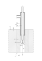
- FIG. 2 is a cross-sectional view showing a heating furnace according to an embodiment of the present invention.
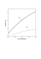
- FIG. 2 is a partially enlarged view of the burner shown in FIG. 1 is a graph showing the relationship between the oxygen concentration of an oxidizer and the adiabatic theoretical flame temperature.
- 1 is a graph showing the relationship between the oxygen concentration of an oxidizer and the combustion rate.
- the heating furnace 6 has at least one burner 1.
- the heating furnace 6 has a furnace side wall 6a on which the burner 1 is installed.
- the burner 1 is embedded in the furnace side wall 6a.
- the arrangement of the burner 1 in the heating furnace 6 is not limited to this.
- the burner 1 burns fuel gas in the internal space 6b of the heating furnace 6 to heat the object to be heated and melt it as necessary.
- Burner 1 uses a fuel gas containing ammonia and a combustion-supporting gas with an oxygen concentration of 30% or more.
- the above configuration makes it possible to realize a burner 1 that uses ammonia as the fuel gas and can ensure radiation intensity and flame stability.
- the fuel gas is not particularly limited as long as it contains ammonia, but it is preferable that it contains ammonia as the main component (i.e., the ammonia component is more than 50% and not more than 100%).
- the combustion supporting gas is not particularly limited as long as it has an oxygen concentration of 30% or more, but it is preferable to use oxygen-enriched air and have an oxygen concentration of 30% or more in the combustion supporting gas.
- the radiation intensity and flame stability of burner 1 are related to the flame temperature and burning speed, and the flame temperature and burning speed are related to the oxygen concentration of the supporting gas.
- the relationship between the oxygen concentration of the oxidizer (supporting gas) and the adiabatic theoretical flame temperature of fossil fuel (methane) and ammonia is as shown in Figure 3
- the relationship between the oxygen concentration of the oxidizer (supporting gas) and the burning speed of fossil fuel (methane) and ammonia is as shown in Figure 4.
- ammonia has a lower flame temperature and burning speed than fossil fuels.
- Equation (1) applies when CH4 is burned in air.
- Equation (2) represents the case where CH4 is burned in oxygen.
- Equation (3) applies when NH3 is burned in air.
- Equation (4) represents the case where NH3 is burned in oxygen.
- the CO 2 and H 2 O contained in the right side of each formula are known as radiant gases, and these gases contribute to the radiation performance of the combustion flame.
- the concentration of each radiant gas is as follows, and it can be seen that changing the oxidant from air to oxygen improves the radiation performance of the flame.
- the CO 2 concentration in the exhaust gas increases.
- the CO 2 concentration is zero, and the concentration of the radiant gas is greater than that in formula (1).
- formula (4) in which the oxidant is changed from air to oxygen, the concentration of the radiant gas is further improved. Therefore, it can be seen that it is effective to increase the oxygen concentration of the oxidant for ammonia, which has a low flame temperature.
- the burner 1 has a fuel gas supply pipe 2a that supplies fuel gas (preferably without premixing oxygen) and ejects it from the fuel gas ejection hole 2a1 at the tip, and a combustion-stimulating gas supply pipe 2b that is provided radially outside the fuel gas supply pipe 2a so as to surround the fuel gas supply pipe 2a (preferably the tip of the fuel gas supply pipe 2a as shown) (preferably as shown so that a flow path for the combustion-stimulating gas is formed between the outer peripheral surface of the fuel gas supply pipe 2a and the inner peripheral surface of the combustion-stimulating gas supply pipe 2b that is spaced from the outer peripheral surface all around), and supplies the combustion-stimulating gas (preferably without premixing fuel) and ejects it from the combustion-stimulating gas ejection hole 2b1 at the tip.
- fuel gas supply pipe 2a that supplies fuel gas (preferably without premixing oxygen) and ejects it from the fuel gas ejection hole 2a1 at the tip
- the fuel gas ejected from the fuel gas ejection hole 2a1 and the combustion-stimulating gas ejected from the combustion-stimulating gas ejection hole 2b1 can be supplied to the burner flame, so that stable ammonia combustion can be achieved while suppressing backfire.
- the fuel gas supply pipe 2a preferably surrounds the central axis O of the combustion supporting gas supply pipe 2b as shown, and more preferably is arranged coaxially with the combustion supporting gas supply pipe 2b as shown.
- the inner and outer circumferential surfaces of the fuel gas supply pipe 2a at the tip of the fuel gas supply pipe 2a and the inner and outer circumferential surfaces of the combustion supporting gas supply pipe 2b at the tip of the combustion supporting gas supply pipe 2b are each circular, but are not limited to this.
- the burner 1 has a burner body 2 that has a double-pipe structure consisting of a fuel gas supply pipe 2a and a combustion-supporting gas supply pipe 2b.
- the fuel gas ejection hole 2a1 is formed on the inner surface of the tip of the fuel gas supply pipe 2a. If the inner diameter at the tip of the fuel gas supply pipe 2a is d1 , the outer diameter is D1 , and the inner diameter at a position a distance from the tip is L1 is d2 , then at a position where 5 ⁇ d1 ⁇ L1 ⁇ 10 ⁇ d1 , d1 ⁇ d2 , and ⁇ ( D1 - d1 )/ D1 ⁇ 100 ⁇ 20.
- the flow path of the fuel gas near the fuel gas ejection hole 2a1 narrows toward the fuel gas ejection hole 2a1, and the supply pressure of the fuel gas increases toward the fuel gas ejection hole 2a1.
- the supply pressure of the fuel gas at the fuel gas ejection hole 2a1 is uniformized, and the uniformity of the ejection amount of the fuel gas at the fuel gas ejection hole 2a1 can be improved.
- the distance between the outer circumferential surface of the flow path of the fuel gas and the inner circumferential surface of the flow path of the combustion-supporting gas at the tip of the fuel gas supply pipe 2a becomes small enough for practical use, and the fuel gas and the combustion-supporting gas can be quickly mixed. Therefore, good stability of the flame due to good mixing can be realized.
- the combustion-supporting gas ejection hole 2b1 is formed on the inner surface of the tip of the combustion-supporting gas supply pipe 2b.
- the inner diameter at the tip of the combustion-supporting gas supply pipe 2b is d3 and the inner diameter at a position where the distance from the tip is L2 is d4 , then at a position where 5 ⁇ d3 ⁇ L2 ⁇ 10 ⁇ d3 , d3 ⁇ d4 ; and the tip of the fuel gas supply pipe 2a is located closer to the base end than the tip of the combustion-supporting gas supply pipe 2b, and when the distance from the tip of the fuel gas supply pipe 2a to the tip of the combustion-supporting gas supply pipe 2b is L3 , then L3 ⁇ 5 ⁇ d3 .
- the mixing chamber 3 can be formed while suppressing the possibility of backfire, and therefore, even better stability of the flame due to better mixing can be achieved.
- the fuel gas supply pipe 2a and the combustion supporting gas supply pipe 2b each extend linearly parallel to the central axis O in a range where 0 ⁇ L 2 ⁇ 10 ⁇ d3 is satisfied.
- the burner 1 has a burner body 2 having a fuel gas supply pipe 2a and a combustion supporting gas supply pipe 2b, and a burner block 4 having an opening 4a in which the burner body 2 is arranged (preferably coaxially as shown).
- a burner body 2 having a fuel gas supply pipe 2a and a combustion supporting gas supply pipe 2b
- a burner block 4 having an opening 4a in which the burner body 2 is arranged (preferably coaxially as shown).
- the tip of the combustion supporting gas supply pipe 2b is located closer to the base end than the tip of the opening 4a, and when the distance from the tip of the opening 4a to the tip of the combustion supporting gas supply pipe 2b is L4 , 0.2 ⁇ ⁇ ( d5 /2) 2 ⁇ ⁇ ⁇ L42 ⁇ 0.5 is satisfied.
- D4 ⁇ d5 ⁇ 1.1 ⁇ D4 the tip of the combustion supporting gas supply pipe 2b is located closer to the base end than the tip of the opening 4a, and 0.2 ⁇ ( d5 /2) 2 ⁇ L42 ⁇ 0.5, so that the opening 4a of the burner block 4 can form a good combustion chamber 5 while protecting the burner body 2 from radiant heat from the installation environment such as an industrial furnace.
- the burner 1 is not limited to a configuration having a burner block 4, and may be configured to have a water-cooled jacket instead of or in addition to the burner block 4.
- the opening 4a is configured as a circular through hole, but is not limited to this.
- burner 2 burner body 2a fuel gas supply pipe 2a1 fuel gas ejection hole 2b combustion supporting gas supply pipe 2b1 combustion supporting gas ejection hole 3 mixing chamber 4 burner block 4a opening 5 combustion chamber 6 heating furnace 6a furnace side wall 6b internal space d1 inner diameter d2 inner diameter d3 inner diameter d4 inner diameter d5 inner diameter D1 outer diameter D2 outer diameter D3 outer diameter D4 outer diameter L1 distance L2 distance L3 distance L4 distance O central axis
Landscapes
- Engineering & Computer Science (AREA)
- Chemical & Material Sciences (AREA)
- Combustion & Propulsion (AREA)
- Mechanical Engineering (AREA)
- General Engineering & Computer Science (AREA)
- Combustion Of Fluid Fuel (AREA)
Abstract
アンモニアを含む燃料ガスと酸素濃度30%以上の支燃性ガスとを用いるバーナ。
Description
本発明はバーナに関する。
燃料ガスと支燃性ガスとを用いるバーナが知られている(例えば特許文献1参照)。
金属加熱炉、ガラス溶解炉、アルミ溶解炉等の工業炉においては、燃料を酸化剤で燃焼させるバーナを熱源とすることが一般的である。燃料には、微粉炭等の固体燃料、灯油若しくは重油等の液体燃料、又は天然ガス若しくはLPG等の気体燃料等の様々な化石燃料が用いられる。工業炉では、燃料を燃焼させた火炎の輻射伝熱によって被加熱物を加熱する。
化石燃料を用いる場合、燃焼排ガス中に多量のCO2を含むことになるため、近年では、アンモニアを用いることが提案されてきている。
アンモニアは燃焼してもCO2を発生しないといった特徴をもつが、一方で炭素が含まれないために火炎の輻射強度が低くなったり、燃焼速度が遅いために火炎が安定しなかったりする問題がある。
そこで本発明の目的は、燃料にアンモニアを用い且つ輻射強度と火炎の安定性とを確保できるバーナを提供することにある。
本発明の一態様は以下のとおりである。
[1]
アンモニアを含む燃料ガスと酸素濃度30%以上の支燃性ガスとを用いるバーナ。
アンモニアを含む燃料ガスと酸素濃度30%以上の支燃性ガスとを用いるバーナ。
[2]
前記燃料ガスを供給し先端の燃料ガス噴出孔から噴出する燃料ガス供給管と、
前記燃料ガス供給管の径方向外側に前記燃料ガス供給管を囲繞するように設けられ、前記支燃性ガスを供給し先端の支燃性ガス噴出孔から噴出する支燃性ガス供給管とを有する、[1]に記載のバーナ。
前記燃料ガスを供給し先端の燃料ガス噴出孔から噴出する燃料ガス供給管と、
前記燃料ガス供給管の径方向外側に前記燃料ガス供給管を囲繞するように設けられ、前記支燃性ガスを供給し先端の支燃性ガス噴出孔から噴出する支燃性ガス供給管とを有する、[1]に記載のバーナ。
[3]
前記燃料ガス供給管と前記支燃性ガス供給管とによる2重管構造であるバーナ本体を有する、[2]に記載のバーナ。
前記燃料ガス供給管と前記支燃性ガス供給管とによる2重管構造であるバーナ本体を有する、[2]に記載のバーナ。
[4]
前記燃料ガス噴出孔は前記燃料ガス供給管の前記先端の内周面で形成され、
前記燃料ガス供給管の前記先端での内径をd1とし、外径をD1とし、先端からの距離がL1となる位置での内径をd2とした時に、
5×d1≦L1≦10×d1となる位置ではd1<d2であり、
{(D1-d1)/D1}×100≦20である、[2]又は[3]に記載のバーナ。
前記燃料ガス噴出孔は前記燃料ガス供給管の前記先端の内周面で形成され、
前記燃料ガス供給管の前記先端での内径をd1とし、外径をD1とし、先端からの距離がL1となる位置での内径をd2とした時に、
5×d1≦L1≦10×d1となる位置ではd1<d2であり、
{(D1-d1)/D1}×100≦20である、[2]又は[3]に記載のバーナ。
[5]
前記支燃性ガス噴出孔は前記支燃性ガス供給管の前記先端の内周面で形成され、
前記支燃性ガス供給管の前記先端での内径をd3とし、先端からの距離がL2となる位置での内径をd4とした時に、
5×d3≦L2≦10×d3となる位置ではd3<d4であり、
前記燃料ガス供給管の前記先端は、前記支燃性ガス供給管の前記先端よりも基端側に位置し、
前記燃料ガス供給管の前記先端から前記支燃性ガス供給管の前記先端までの距離をL3とした時に、
L3<5×d3である、[2]~[4]の何れか1項に記載のバーナ。
前記支燃性ガス噴出孔は前記支燃性ガス供給管の前記先端の内周面で形成され、
前記支燃性ガス供給管の前記先端での内径をd3とし、先端からの距離がL2となる位置での内径をd4とした時に、
5×d3≦L2≦10×d3となる位置ではd3<d4であり、
前記燃料ガス供給管の前記先端は、前記支燃性ガス供給管の前記先端よりも基端側に位置し、
前記燃料ガス供給管の前記先端から前記支燃性ガス供給管の前記先端までの距離をL3とした時に、
L3<5×d3である、[2]~[4]の何れか1項に記載のバーナ。
[6]
前記燃料ガス供給管及び前記支燃性ガス供給管を有するバーナ本体と、
前記バーナ本体が配置される開口部を有するバーナブロックとを有し、
前記開口部に配置される部分での前記支燃性ガス供給管の最大の外径をD4とし、前記開口部の先端での内径をD5とした時に、
D4≦D5≦1.1×D4であり、
前記支燃性ガス供給管の前記先端は、前記開口部の前記先端よりも基端側に位置し、
前記開口部の前記先端から前記支燃性ガス供給管の前記先端までの距離をL4とした時に、
0.2≦{(D5/2)2×π}÷L4 2≦0.5である、[2]~[5]の何れか1項に記載のバーナ。
前記燃料ガス供給管及び前記支燃性ガス供給管を有するバーナ本体と、
前記バーナ本体が配置される開口部を有するバーナブロックとを有し、
前記開口部に配置される部分での前記支燃性ガス供給管の最大の外径をD4とし、前記開口部の先端での内径をD5とした時に、
D4≦D5≦1.1×D4であり、
前記支燃性ガス供給管の前記先端は、前記開口部の前記先端よりも基端側に位置し、
前記開口部の前記先端から前記支燃性ガス供給管の前記先端までの距離をL4とした時に、
0.2≦{(D5/2)2×π}÷L4 2≦0.5である、[2]~[5]の何れか1項に記載のバーナ。
[7]
[1]~[6]の何れか1項に記載されたバーナが、少なくとも1基以上設置された加熱炉。
[1]~[6]の何れか1項に記載されたバーナが、少なくとも1基以上設置された加熱炉。
本発明によれば、燃料にアンモニアを用い且つ輻射強度と火炎の安定性とを確保できるバーナを提供することができる。
以下、図面を参照しつつ本発明の実施形態を例示説明する。
図1~図2に示すように、本発明の一実施形態において加熱炉6は、少なくとも1基以上のバーナ1を有する。加熱炉6は、バーナ1が設置された炉側壁6aを有する。バーナ1は、炉側壁6aに埋設される。なお、バーナ1の加熱炉6への配置はこれに限定されない。バーナ1は、加熱炉6の内部空間6bで燃料ガスを燃焼させて被加熱物を加熱し、必要に応じて溶融させる。
バーナ1は、アンモニアを含む燃料ガスと酸素濃度30%以上の支燃性ガスとを用いる。
上記構成によれば、燃料ガスにアンモニアを用い且つ輻射強度と火炎の安定性とを確保できるバーナ1を実現できる。燃料ガスは、アンモニアを含む限り特に限定されないが、アンモニアを主成分として含む(すなわちアンモニア成分が50%を超え100%以下である)ことが好ましい。支燃性ガスは、酸素濃度30%以上であれば特に限定されないが、酸素富化空気を用い支燃性ガス中の酸素濃度が30%以上となる構成とすることが好ましい。
バーナ1の輻射強度及び火炎の安定性は、火炎温度及び燃焼速度に関係し、火炎温度及び燃焼速度は、支燃性ガスの酸素濃度に関係する。例えば、酸化剤(支燃性ガス)の酸素濃度と化石燃料(メタン)及びアンモニアの断熱理論火炎温度との関係は図3に示すとおりであり、酸化剤(支燃性ガス)の酸素濃度と化石燃料(メタン)及びアンモニアの燃焼速度との関係は図4に示すとおりである。このように、アンモニアは化石燃料に比べて火炎温度及び燃焼速度が低い。以上に鑑み、支燃性ガスの酸素濃度を30%以上とすることで、工業炉での実用に十分な輻射強度と火炎の安定性とを確保できることが分かった。
一般的な化石燃料の主成分であるCH4(メタン)とNH3(アンモニア)の燃焼時の化学式を比較すると以下のとおりとなる。
(1)CH4+2O2+8N2→CO2+2H2O+8N2
(2)CH4+2O2→CO2+2H2O
(3)NH3+0.75O2+3N2→1.5H2O+3.5N2
(4)NH3+0.75O2→1.5H2O+0.5N2
式(1)は、CH4を空気中で燃焼させた場合である。
式(2)は、CH4を酸素中で燃焼させた場合である。
式(3)は、NH3を空気中で燃焼させた場合である。
式(4)は、NH3を酸素中で燃焼させた場合である。
(1)CH4+2O2+8N2→CO2+2H2O+8N2
(2)CH4+2O2→CO2+2H2O
(3)NH3+0.75O2+3N2→1.5H2O+3.5N2
(4)NH3+0.75O2→1.5H2O+0.5N2
式(1)は、CH4を空気中で燃焼させた場合である。
式(2)は、CH4を酸素中で燃焼させた場合である。
式(3)は、NH3を空気中で燃焼させた場合である。
式(4)は、NH3を酸素中で燃焼させた場合である。
各式の右辺に含まれるCO2とH2Oは輻射性ガスとして知られ、これらのガスが燃焼火炎の輻射性能に寄与する。各式を比較すると、各輻射性ガスの濃度が以下のとおりであり、酸化剤を空気から酸素に変更することで火炎の輻射性能が向上することが分かる。しかし、式(2)においては、排ガス中のCO2濃度が増大してしまう。また、式(3)ではCO2濃度はゼロであり、輻射性ガスの濃度は式(1)よりも大きい。さらに、酸化剤を空気から酸素に変更した式(4)では、輻射性ガスの濃度がさらに向上する。したがって、火炎温度の低いアンモニアでは、酸化剤の酸素濃度を高めることが有効であることが分かる。

バーナ1は、燃料ガスを(好ましくは酸素を予混合せずに)供給し先端の燃料ガス噴出孔2a1から噴出する燃料ガス供給管2aと、燃料ガス供給管2aの径方向外側に燃料ガス供給管2a(好ましくは図示のように燃料ガス供給管2aの先端部)を囲繞するように(好ましくは図示のように、燃料ガス供給管2aの外周面と当該外周面から全周に亘って離間する支燃性ガス供給管2bの内周面との間に支燃性ガスの流路が形成されるように)設けられ、支燃性ガスを(好ましくは燃料を予混合せずに)供給し先端の支燃性ガス噴出孔2b1から噴出する支燃性ガス供給管2bとを有する。上記構成によれば、バーナ火炎に燃料ガス噴出孔2a1から噴出する燃料ガスと支燃性ガス噴出孔2b1から噴出する支燃性ガスとを供給できるので、逆火を抑制しつつ安定したアンモニアの燃焼を実現できる。燃料ガス供給管2aは好ましくは図示のように支燃性ガス供給管2bの中心軸線Oを囲繞し、より好ましくは図示のように支燃性ガス供給管2bと同軸に設けられる。燃料ガス供給管2aの先端での燃料ガス供給管2aの内周面及び外周面と、支燃性ガス供給管2bの先端での支燃性ガス供給管2bの内周面及び外周面とは、本実施形態ではそれぞれ円形であるがこれに限らない。
バーナ1は、燃料ガス供給管2aと支燃性ガス供給管2bとによる2重管構造であるバーナ本体2を有する。上記構成によれば、簡単な構造で輻射強度と火炎の安定性とを確保できる。
燃料ガス噴出孔2a1は燃料ガス供給管2aの先端の内周面で形成され、燃料ガス供給管2aの先端での内径をd1とし、外径をD1とし、先端からの距離がL1となる位置での内径をd2とした時に、5×d1≦L1≦10×d1となる位置ではd1<d2であり、{(D1-d1)/D1}×100≦20である。上記構成によれば、5×d1≦L1≦10×d1となる位置ではd1<d2であることで、燃料ガス噴出孔2a1の付近で燃料ガスの流路が燃料ガス噴出孔2a1に向かって狭くなるため、燃料ガスの供給圧力が燃料ガス噴出孔2a1に向かって大きくなり、その結果、燃料ガス噴出孔2a1での燃料ガスの供給圧力が均一化されるため、燃料ガス噴出孔2a1での燃料ガスの噴出量の均一性を向上できる。また、{(D1-d1)/D1}×100≦20であることで、燃料ガス供給管2aの先端において、燃料ガスの流路の外周面と支燃性ガスの流路の内周面との距離が実用上十分に小さくなることで、燃料ガスと支燃性ガスとの速やかな混合を実現できる。したがって、良好な混合による火炎の良好な安定性を実現できる。
支燃性ガス噴出孔2b1は支燃性ガス供給管2bの先端の内周面で形成され、支燃性ガス供給管2bの先端での内径をd3とし、先端からの距離がL2となる位置での内径をd4とした時に、5×d3≦L2≦10×d3となる位置ではd3<d4であり、燃料ガス供給管2aの先端は、支燃性ガス供給管2bの先端よりも基端側に位置し、燃料ガス供給管2aの先端から支燃性ガス供給管2bの先端までの距離をL3とした時に、L3<5×d3である。上記構成によれば、5×d3≦L2≦10×d3となる位置ではd3<d4であることで、支燃性ガスの流路が支燃性ガス噴出孔2b1に向かって狭くなるため、支燃性ガスの供給圧力が支燃性ガス噴出孔2b1に向かって大きくなり、その結果、支燃性ガス噴出孔2b1での支燃性ガスの供給圧力が均一化されるため、支燃性ガス噴出孔2b1での支燃性ガスの噴出量の均一性を向上できる。また、燃料ガス供給管2aの先端が支燃性ガス供給管2bの先端よりも基端側に位置し、L3<5×d3であることで、逆火が生じる可能性を抑制しつつ混合室3を形成できるため、より一層良好な混合による火炎のより一層良好な安定性を実現できる。燃料ガス供給管2a及び支燃性ガス供給管2bはそれぞれ、本実施形態では、少なくとも0≦L2≦10×d3となる範囲において中心軸線Oに平行に直線状に延びる。
バーナ1は、燃料ガス供給管2a及び支燃性ガス供給管2bを有するバーナ本体2と、バーナ本体2が(好ましくは図示のように同軸に)配置される開口部4aを有するバーナブロック4とを有し、開口部4aに配置される部分での支燃性ガス供給管2bの最大の外径をD4とし、開口部4aの先端での内径をd5とした時に、D4≦d5≦1.1×D4であり、支燃性ガス供給管2bの先端は、開口部4aの先端よりも基端側に位置し、開口部4aの先端から支燃性ガス供給管2bの先端までの距離をL4とした時に、0.2≦{(d5/2)2×π}÷L4
2≦0.5である。上記構成によれば、D4≦d5≦1.1×D4であり、支燃性ガス供給管2bの先端が開口部4aの先端よりも基端側に位置し、0.2≦{(d5/2)2×π}÷L4
2≦0.5であることで、バーナブロック4の開口部4aによって良好な燃焼室5を形成しつつ工業炉などの設置環境からの輻射熱からバーナ本体2を保護できる。なお、バーナ1はバーナブロック4を有する構成に限らず、例えば、バーナブロック4に代えて、又は加えて、水冷ジャケットを有する構成としてもよい。開口部4aは本実施形態では円形の貫通穴で構成されるがこれに限らない。
本発明の実施形態について前述したが、本発明は前述した実施形態に限定されず、前述した実施形態は本発明の要旨を逸脱しない範囲で種々変更できる。
1 バーナ
2 バーナ本体
2a 燃料ガス供給管
2a1 燃料ガス噴出孔
2b 支燃性ガス供給管
2b1 支燃性ガス噴出孔
3 混合室
4 バーナブロック
4a 開口部
5 燃焼室
6 加熱炉
6a 炉側壁
6b 内部空間
d1 内径
d2 内径
d3 内径
d4 内径
d5 内径
D1 外径
D2 外径
D3 外径
D4 外径
L1 距離
L2 距離
L3 距離
L4 距離
O 中心軸線
2 バーナ本体
2a 燃料ガス供給管
2a1 燃料ガス噴出孔
2b 支燃性ガス供給管
2b1 支燃性ガス噴出孔
3 混合室
4 バーナブロック
4a 開口部
5 燃焼室
6 加熱炉
6a 炉側壁
6b 内部空間
d1 内径
d2 内径
d3 内径
d4 内径
d5 内径
D1 外径
D2 外径
D3 外径
D4 外径
L1 距離
L2 距離
L3 距離
L4 距離
O 中心軸線
Claims (7)
- アンモニアを含む燃料ガスと酸素濃度30%以上の支燃性ガスとを用いるバーナ。
- 前記燃料ガスを供給し先端の燃料ガス噴出孔から噴出する燃料ガス供給管と、
前記燃料ガス供給管の径方向外側に前記燃料ガス供給管を囲繞するように設けられ、前記支燃性ガスを供給し先端の支燃性ガス噴出孔から噴出する支燃性ガス供給管とを有する、請求項1に記載のバーナ。 - 前記燃料ガス供給管と前記支燃性ガス供給管とによる2重管構造であるバーナ本体を有する、請求項2に記載のバーナ。
- 前記燃料ガス噴出孔は前記燃料ガス供給管の前記先端の内周面で形成され、
前記燃料ガス供給管の前記先端での内径をd1とし、外径をD1とし、先端からの距離がL1となる位置での内径をd2とした時に、
5×d1≦L1≦10×d1となる位置ではd1<d2であり、
{(D1-d1)/D1}×100≦20である、請求項2に記載のバーナ。 - 前記支燃性ガス噴出孔は前記支燃性ガス供給管の前記先端の内周面で形成され、
前記支燃性ガス供給管の前記先端での内径をd3とし、先端からの距離がL2となる位置での内径をd4とした時に、
5×d3≦L2≦10×d3となる位置ではd3<d4であり、
前記燃料ガス供給管の前記先端は、前記支燃性ガス供給管の前記先端よりも基端側に位置し、
前記燃料ガス供給管の前記先端から前記支燃性ガス供給管の前記先端までの距離をL3とした時に、
L3<5×d3である、請求項2に記載のバーナ。 - 前記燃料ガス供給管及び前記支燃性ガス供給管を有するバーナ本体と、
前記バーナ本体が配置される開口部を有するバーナブロックとを有し、
前記開口部に配置される部分での前記支燃性ガス供給管の最大の外径をD4とし、前記開口部の先端での内径をD5とした時に、
D4≦D5≦1.1×D4であり、
前記支燃性ガス供給管の前記先端は、前記開口部の前記先端よりも基端側に位置し、
前記開口部の前記先端から前記支燃性ガス供給管の前記先端までの距離をL4とした時に、
0.2≦{(D5/2)2×π}÷L4 2≦0.5である、請求項2に記載のバーナ。 - 請求項1~6の何れか1項に記載されたバーナが、少なくとも1基以上設置された加熱炉。
Applications Claiming Priority (2)
| Application Number | Priority Date | Filing Date | Title |
|---|---|---|---|
| JP2023-189530 | 2023-11-06 | ||
| JP2023189530 | 2023-11-06 |
Publications (1)
| Publication Number | Publication Date |
|---|---|
| WO2025100243A1 true WO2025100243A1 (ja) | 2025-05-15 |
Family
ID=95695425
Family Applications (1)
| Application Number | Title | Priority Date | Filing Date |
|---|---|---|---|
| PCT/JP2024/037822 Pending WO2025100243A1 (ja) | 2023-11-06 | 2024-10-23 | バーナ |
Country Status (1)
| Country | Link |
|---|---|
| WO (1) | WO2025100243A1 (ja) |
Citations (6)
| Publication number | Priority date | Publication date | Assignee | Title |
|---|---|---|---|---|
| JPH06147437A (ja) * | 1992-11-02 | 1994-05-27 | Chugai Ro Co Ltd | 燃料ノズル |
| JPH11257613A (ja) * | 1998-03-12 | 1999-09-21 | Miyamoto Kogyosho:Kk | バーナ |
| JP2000346316A (ja) * | 1999-06-02 | 2000-12-15 | Nippon Sanso Corp | 燃焼装置 |
| CN105674319A (zh) * | 2014-11-20 | 2016-06-15 | 宋亚民 | 基于氨气和氧气的复合燃料系统 |
| CN106678802A (zh) * | 2016-11-28 | 2017-05-17 | 无锡市莱达热工工程有限公司 | 熔化炉的煤气烧嘴结构 |
| JP2023119728A (ja) * | 2022-02-17 | 2023-08-29 | 東京瓦斯株式会社 | バーナ |
-
2024
- 2024-10-23 WO PCT/JP2024/037822 patent/WO2025100243A1/ja active Pending
Patent Citations (6)
| Publication number | Priority date | Publication date | Assignee | Title |
|---|---|---|---|---|
| JPH06147437A (ja) * | 1992-11-02 | 1994-05-27 | Chugai Ro Co Ltd | 燃料ノズル |
| JPH11257613A (ja) * | 1998-03-12 | 1999-09-21 | Miyamoto Kogyosho:Kk | バーナ |
| JP2000346316A (ja) * | 1999-06-02 | 2000-12-15 | Nippon Sanso Corp | 燃焼装置 |
| CN105674319A (zh) * | 2014-11-20 | 2016-06-15 | 宋亚民 | 基于氨气和氧气的复合燃料系统 |
| CN106678802A (zh) * | 2016-11-28 | 2017-05-17 | 无锡市莱达热工工程有限公司 | 熔化炉的煤气烧嘴结构 |
| JP2023119728A (ja) * | 2022-02-17 | 2023-08-29 | 東京瓦斯株式会社 | バーナ |
Similar Documents
| Publication | Publication Date | Title |
|---|---|---|
| JP4309380B2 (ja) | 点火支援燃料ランスを有する多段燃焼システム | |
| RU2426030C2 (ru) | УЗЕЛ ГОРЕЛОК С УЛЬТРАНИЗКОЙ ЭМИССИЕЙ NOx | |
| CN108224425A (zh) | 氢气燃烧器结构及包括氢气燃烧器结构的氢气燃烧器装置 | |
| EP0664871A1 (en) | BURNER WITH STEP-IN AIR INTRODUCTION, RECYCLING OF BURNED GASES AND LOW NOx EMISSION RATE. | |
| JP2022154831A (ja) | バーナ | |
| JP2025063289A (ja) | マルチノズルバーナによる工業炉、特に、ガラス炉または金属溶融炉における水素燃焼の方法およびバーナ | |
| JP2524025B2 (ja) | 低カロリ―ガスの燃焼バ―ナ構造およびその燃焼方法 | |
| JP7410642B2 (ja) | 特殊バーナ | |
| US6718773B2 (en) | Method for igniting a thermal turbomachine | |
| JP2025077384A (ja) | バーナ | |
| RU99596U1 (ru) | Горелочное устройство | |
| CN114466693A (zh) | 无机质球状化粒子制造装置及无机质球状化粒子制造方法 | |
| WO2025100243A1 (ja) | バーナ | |
| JP2022130326A (ja) | バーナ | |
| WO2025100242A1 (ja) | バーナ | |
| JP2001108225A (ja) | 混焼バーナおよびそれを用いた排ガス処理装置 | |
| JP2025077385A (ja) | バーナ | |
| JP2015525333A (ja) | 液体燃料の触媒燃焼を行うための触媒加熱器と反応器とに使用される燃料噴射システム | |
| RU19312U1 (ru) | Устройство для розжига и подсветки пылеугольного факела | |
| JP4323686B2 (ja) | 低NOxバーナ及びその運転方法 | |
| JP7262521B2 (ja) | ガスバーナ、及び燃焼設備 | |
| JP6894297B2 (ja) | 燃焼器 | |
| RU2642997C2 (ru) | Газовая горелка с низким содержанием оксидов азота и способ сжигания топливного газа | |
| RU211642U1 (ru) | Горелочное устройство для сжигания низкокалорийного газа | |
| RU50280U1 (ru) | Вспомогательное горелочное устройство для плазменного воспламенения и стабилизации горения низкореакционного пылеугольного топлива основных горелок теплового агрегата |
Legal Events
| Date | Code | Title | Description |
|---|---|---|---|
| 121 | Ep: the epo has been informed by wipo that ep was designated in this application |
Ref document number: 24888541 Country of ref document: EP Kind code of ref document: A1 |
|
| ENP | Entry into the national phase |
Ref document number: 2025556310 Country of ref document: JP Kind code of ref document: A |
|
| WWE | Wipo information: entry into national phase |
Ref document number: 2025556310 Country of ref document: JP |