WO2025088877A1 - 制御装置、制御システム、および制御方法 - Google Patents
制御装置、制御システム、および制御方法 Download PDFInfo
- Publication number
- WO2025088877A1 WO2025088877A1 PCT/JP2024/029069 JP2024029069W WO2025088877A1 WO 2025088877 A1 WO2025088877 A1 WO 2025088877A1 JP 2024029069 W JP2024029069 W JP 2024029069W WO 2025088877 A1 WO2025088877 A1 WO 2025088877A1
- Authority
- WO
- WIPO (PCT)
- Prior art keywords
- data
- unit
- application
- address
- information
- Prior art date
- Legal status (The legal status is an assumption and is not a legal conclusion. Google has not performed a legal analysis and makes no representation as to the accuracy of the status listed.)
- Pending
Links
Images











Classifications
-
- G—PHYSICS
- G06—COMPUTING OR CALCULATING; COUNTING
- G06F—ELECTRIC DIGITAL DATA PROCESSING
- G06F11/00—Error detection; Error correction; Monitoring
-
- G—PHYSICS
- G06—COMPUTING OR CALCULATING; COUNTING
- G06F—ELECTRIC DIGITAL DATA PROCESSING
- G06F13/00—Interconnection of, or transfer of information or other signals between, memories, input/output devices or central processing units
- G06F13/10—Program control for peripheral devices
-
- G—PHYSICS
- G06—COMPUTING OR CALCULATING; COUNTING
- G06F—ELECTRIC DIGITAL DATA PROCESSING
- G06F13/00—Interconnection of, or transfer of information or other signals between, memories, input/output devices or central processing units
- G06F13/38—Information transfer, e.g. on bus
Definitions
- the present invention relates to the configuration of a control device that controls industrial equipment, and in particular to technology that enables multiple devices to exchange data with each other and work together.
- a communications driver on the OS installed in the CPU (Central Processing Unit) accesses memory and peripheral devices to send and receive data, so the load on the CPU increases according to the amount of data received, which can affect the operation of the control application.
- OS Operating System
- CPU Central Processing Unit
- the background technology in this technical field is, for example, technology such as that in Patent Document 1.
- Patent Document 1 According to the "Abstract" of Patent Document 1, "When receiving and temporarily storing data that is repeatedly generated at a period of PRI (predetermined repetition interval), the reception completion interrupts that are generated each time data is received are consolidated and notified to the CPU as a single collective acknowledgment, thereby reducing the processing load required for the reception completion response processing.
- each signal processor selectively receives a series of data to which identification information matching its own identification information is added, thereby configuring the signal processing device in a round robin format using multiple signal processors, and by performing pipeline processing on a signal processor basis, signal processing is performed on all data without omission even when the reception time of the data to be processed is less than the signal processing time.
- industrial equipment control devices have limited CPU processing power.
- embedded controllers used in industrial sites such as factories have limited CPU processing power and number compared to computers equipped with high-performance CPUs, and the load on the CPU caused by the increase in communication data volume cannot be ignored.
- Industrial equipment is sometimes newly installed in response to changes in demand, or replaced with new equipment, and the applications installed in the control devices are updated as control technology advances.
- the applications installed in the control devices are updated as control technology advances.
- a system is configured so that part of the system is updated while other devices and applications are not, then in addition to the newly added data due to the update, data that is no longer used after the update will be sent to each device in the same way as before the update. This increases the load on the CPU that processes the data reception, and can lead to delays or halts in control processing.
- Patent Document 1 makes it possible to discard data that is not addressed to the device itself, but does not consider how to reduce the unnecessary load on the CPU caused by receiving unused data, even if the data is addressed to the device itself.
- the object of the present invention is to provide a control device, control system, and control method that transmits necessary data used by devices and applications to a CPU.
- the present invention provides a control device comprising a data processing device that outputs data to be used in an application from among input data transmitted from an external device, and an arithmetic processing unit having an application that performs a predetermined arithmetic processing using data from the data processing device, the data processing device comprising a receiving unit that receives and processes the input data, a received data holding unit that holds the input data received by the receiving unit, a selected data holding unit that holds only data to be used in the arithmetic processing unit from among the input data held in the received data holding unit and outputs the held data in accordance with a received data transfer command, and an operating status indicating the type of application currently running in the arithmetic processing unit.
- the system has an address correspondence information generating unit that generates address correspondence information between the address of the input data stored in the received data storage unit and the address of the selected data storage unit that is the storage destination from the active application information, a data extraction unit that generates a control signal including a write address and whether each data in the received data storage unit can be written to the selected data storage unit based on the address correspondence information, and adds the control signal to the data output from the received data storage unit and supplies it to the selected data storage unit, and a data transfer determination unit that transmits a data transfer command to the selected data storage unit to transfer the data held in the selected data storage unit to the arithmetic processing unit, and the arithmetic processing unit transmits type information of the active application to the address correspondence information generating unit.
- the present invention by selecting from the data received from an external device only the data that is to be used by an application running on the CPU and sending it to the CPU, it is possible to reduce the load on the CPU related to data reception.
- 1 is a configuration example of a control device according to a first embodiment of the present invention.
- 3 is an example of a data format according to the first embodiment of the present invention.
- 4 is a configuration example of a received data holding unit according to the first embodiment of the present invention.
- 4 is a configuration example of an address correspondence information generating unit according to the first embodiment of the present invention.
- 4 is an example of stored contents of an access information storage unit according to the first embodiment of the present invention.
- 5 is an example of a selection table of a received data holding unit according to the first embodiment of the present invention.
- 13 is an example of a determination table of a storage destination determination unit according to the first embodiment of the present invention.
- 4 is a configuration example of a data extraction unit according to the first embodiment of the present invention.
- 4 illustrates a data format input to a data extraction unit according to the first embodiment of the present invention.
- 4 is an example of a selection table of a selection signal generating unit according to the first embodiment of the present invention.
- 4 is a configuration example of a selection data storage unit according to the first embodiment of the present invention.
- 4 is a configuration example of a selection data buffer according to the first embodiment of the present invention.
- 4 is an example of a management table according to the first embodiment of the present invention.
- 4 is a configuration example of a data transfer determination unit according to the first embodiment of the present invention.
- 13 is an example of a process flow of a forwarding determination unit according to the first embodiment of the present invention. 13 is an example of stored contents of an access information storage unit according to the second embodiment of the present invention.
- 13 is an example of a selection table of a received data holding unit according to the second embodiment of the present invention.
- 13 is an example of a decision table of a storage destination decision unit according to the second embodiment of the present invention.
- 13 is a configuration example of a control device according to a third embodiment of the present invention.
- 13 is a configuration example of a control device according to a fourth embodiment of the present invention.
- 13 is a configuration example of a control device according to a fifth embodiment of the present invention.
- 13 is a screen display example according to the sixth embodiment of the present invention.
- 13 is a screen display example according to the sixth embodiment of the present invention.
- 13 is a screen display example according to the sixth embodiment of the present invention.
- 13 is a screen display example according to the sixth embodiment of the present invention.
- 13 is a screen display example according to the sixth embodiment of the present invention.
- 13 is a screen display example according to the sixth embodiment of the present invention.
- 13 is a screen display example according to the sixth embodiment
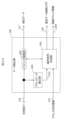
- the control device 101 of this embodiment receives data 200 from external devices to be controlled (such as industrial robots and power supply systems) and outputs control command values 210 for those devices. It mainly comprises a calculation processing unit (CPU) 102 that performs calculations according to a program, and a data processing device 103 that selects data to be sent to the CPU 102 from the received data 200.
- CPU calculation processing unit
- the CPU 102 is equipped with an application 104 that generates a control command value 210 based on the received data.
- the application 104 may also perform various processes required for control, such as data analysis.
- the data processing device 103 includes a receiving unit 105 that receives data 200 transmitted from an external device, a received data holding unit 106 that acts as a buffer circuit that stores and temporarily saves the received data, an address correspondence information generating unit 107 that determines which of the received data is to be transmitted to the CPU 102, a data extraction unit 108 that extracts data to be transmitted from the received data holding unit 106 to the CPU 102, a selected data holding unit 109 that temporarily holds the extracted data, and a data transfer determination unit 110 that gives the selected data holding unit 109 an instruction signal to transmit data to the CPU 102, etc.
- the data processing device 103 also includes a control unit (not shown) that controls the operation of each unit in the data processing device 103 and data transfer.
- (2) Data Format Fig. 1B is a diagram showing an example of the data format of data 200 transmitted from an external device, which is composed of a header section 201 and a data body section 202, and is transmitted in this frame unit at a predetermined cycle or irregularly at the occurrence of an event.
- the header section 201 includes information on the transmission source device, information on the transmission destination device, information on application software used at the transmission destination, etc.
- the data body section 202 includes control data such as measurement values of various sensors for generating control commands for the external device.
- the frame of data 200 may also include a predetermined bit string indicating the beginning or end of the frame, a code for error correction, etc. (not shown).
- (3) Configuration and Function of Each Part of the Data Processing Device (3-1) Receiving Unit
- the receiving unit 105 is composed of a receiving circuit (not shown) that receives data 200 transmitted from an external device and performs loss compensation for the signal waveform, etc., and outputs the reproduced data 122 to the received data holding unit 106.
- (3-2) Received Data Storage Unit The configuration of the received data storage unit 106 will be described with reference to Fig. 2.
- the received data storage unit 106 is made up of a memory device, and stores data 122 from the receiving unit 105 in free addresses 106A on a frame-by-frame basis.
- the data consists of header information and a data body portion, and is stored in the header information storage unit 106B1 and the data body storage unit 106B2, respectively.
- the data format may be transformed into a format used by the application 104, following the processing contents of the communication driver.
- Header information 106B1 and its address 106A of the data stored in the received data storage unit 106 are sent to the address correspondence information generation unit 107 as received data information 123.
- header information 106B1 and data body 106B2, together with the address 106A, are output to the data extraction unit 108 at a predetermined timing as total received data 126.
- the data stored in the received data holding unit 106 may be deleted from the received data holding unit 106 when it is output to the data extraction unit 108, or may be held until a separate deletion command or the like is received depending on the processing content or the like in the application 104. Also, the storage location of the data may be set in an area depending on the data format. 3A, the main components of the address correspondence information generating unit 107 will be described.
- the address correspondence information generating unit 107 includes an access information storage unit 300, a received data selecting unit 301, and a storage destination determining unit 302.
- the access information storage unit 300 stores the type of app (access information) running in the application 104.
- the received data selection unit 301 compares the access information of the application running in the application 104 with the received data information 123, selects the received data to send to the CPU 102, and outputs the address information 311 of the corresponding received data storage unit 106.
- the storage destination determination unit 302 determines the storage destination in the selected data holding unit 109 for each received data based on the address 311 of the received data holding unit 106 received from the received data selection unit and the configuration information 124 of the selected data holding unit 109, and outputs it as address correspondence information 125.
- (3-3-2) Details of Each Component (3-3-2-1) Access Information Storage Unit First, details of the access information storage unit 300 will be described. Here, type information of an app running in the application 104 is stored. Information on the type of an app running (in use) is periodically transmitted from the application 104 at a predetermined timing as the application's access information 121, and the app type is stored.
- FIG. 3B is an example of the contents stored in the access information storage unit 300.
- “app A” and “app D” are stored as “operating (in use) app information 300A.”
- "paused app information 300B” indicating apps that are not used in this embodiment but are currently temporarily stopped from being used
- “previously operating apps 300C” indicating apps that have been used in the past but are not currently being used may also be stored.
- the contents of the “running application information 300A” in the access information storage unit 300 may be set to all conceivable application types at the time of initial setup, and may be deleted at regular intervals, or when the installed applications or system are updated, or by an administrator.
- (3-3-2-2) Received Data Selection Unit As described above, the received data selection unit 301 manages the addresses at which data used by an application running on the application 104 is stored for each piece of data primarily stored in the received data storage unit 106, and has a selection table 301A as shown in FIG. 3C.
- the selection table 301A has an address 301A1 of each received data stored in the received data storage unit 106, application type information 301A2 corresponding to the received data, and access information 310A3 indicating whether the received data is running in the application 104.
- the received data selection unit 301 sequentially receives received data information 123 (address information 106A and header information 106B1; see FIG. 2) from the received data storage unit 106, recognizes the type of application associated with the data from the header information 106B1 ("App A", "App B”, etc.), and sequentially records the address of the received data storage unit as 301A1 and application type information as 301A2.
- the selection table 301A as shown in FIG. 3B is output to the storage destination determination unit 302. (3-3-2-3) Storage Destination Determination Unit Based on the selection table 301A ( Figure 3C) output from the received data selection unit 301, the storage destination determination unit 302 identifies the data that should be stored in the selected data storage unit 109 from the data stored in the received data storage unit 106, and links each address of the received data storage unit 106 to the selected data storage unit 109 address.
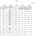
- decision table 302A as shown in FIG. 3D is used.
- received data storage unit address 302A1, application type information 302A2, and application access 302A3 correspond to "received data storage unit address 301A1," "application type information 301A2,” and "application access 301A3" in selection table 301A (FIG. 3C), respectively.
- the storage flag 302A4 in the selection data holding unit is set to "1" for data for which application access 302A3 is “Yes” and set to "0" for data for which application access 302A3 is “No.” This means that data for which storage flag 302A4 is "1” is stored in the selection data holding unit 109, and data for which storage flag 302A4 is "0" is not stored.
- the storage destination determination unit 302 also receives selected data storage unit information 124 about the usage status (availability) of each address from the selected data storage unit 109, and links the addresses. Address linking is performed by allocating available addresses in order starting from the first address of the selected data storage unit.
- the contents of the storage destination determination table in FIG. 3D are sent to the data extraction unit 108 as address correspondence information 125.
- the received data selection unit 301 creates the selection table 301A
- the storage destination determination unit 302 creates the storage destination determination table 302A based on the selection table 301A.
- the functions of the received data selection unit 301 and the storage destination determination unit 302 may be integrated to directly create the storage destination determination table 302A.
- the configuration of the data extraction unit 108 will be described using FIG. 4A.
- the data extraction unit 108 has an address data extraction unit 600, a selection signal generation unit 601, and a timing adjustment unit 602.
- All received data 126 from the received data storage unit 106 is input to the address data extraction unit 600 and timing adjustment unit 602 in the form of serial data as shown in FIG. 4B, starting with the data stored at address R0 (Data0 (header information + data body)).
- the address data extraction unit 600 extracts the address data 610 (R0, R1, R2, %) of each data in the received data storage unit 106 contained in the received total data 126, and passes it to the selection signal generation unit 601.
- the selection signal generating unit 601 outputs a selection signal that determines which of all the received data is to be stored in the selected data storage unit, and if so, in which address the data is to be stored, based on the address correspondence information 125 output from the address correspondence information generating unit 107.
- the selection signal generation unit 601 shares the same contents as decision table 302A shown in FIG. 3D as selection table 400 shown in FIG. 4C, and compares address data 610 (R0, R1, R2, ...) from address data extraction unit 600 with "received data storage unit address 400A" in selection table 400, and transmits the corresponding stored contents of "selection data storage unit storage flag 400B” and “selection data storage unit storage address 400C” to selection data storage unit 109 as selection data storage flag 128 and storage address information 128A, respectively.
- the timing adjustment unit 602 performs delay processing or the like on all input received data 126 as necessary in order to match the transmission timing of the selected data storage flag 128 and storage address information 128A transmitted from the selection signal generation unit 601 to the selected data holding unit 109 with the corresponding data of all received data 126.
- the address data (R0, R1, R2, ...) of the received data holding unit 106 included in the all received data 126 may be deleted.
- the data subjected to the above processing by the timing adjustment unit 602 is transmitted to the selected data holding unit 109 as extracted data 127 together with the selected data storage flag 128 and storage address information 128A. 5A, the configuration of the selected data holding unit 109 will be described.
- the selected data holding unit 109 has a selected data buffer 901, a buffer management unit 902, and a buffer timer 903.
- the selected data buffer 901 stores the extracted data 127 extracted by the data extraction unit 108, and is realized by a memory device as shown in FIG. 5B. However, since it only stores selected data, it can be implemented with a smaller storage capacity than the memory device of the received data holding unit 106.
- the capacity of the memory device may be determined according to the application, the specifications of the control device to be implemented, the capabilities of the CPU 102, etc.
- the selected data storage flag 128 and storage address information 128A output by the data extraction unit 108 are referenced, and if the storage flag 128 is "1", the data is stored at the address indicated by the simultaneously received storage address 128A.
- the selected data buffer 901 is a general memory device
- the received extracted data 127, selected data storage flag 128, and storage address information 128A correspond to write data, a write enable signal, and a write address signal, respectively.
- the data stored in the selected data buffer 901 is read out by a control signal 911 from the buffer management unit 902 and is sent as selected data 129 to the application 104 of the CPU 102 at a predetermined timing.
- the buffer management unit 902 manages the usage status of the selected data buffer 901 and generates the read control signal described above. In addition, it transmits free space information to the address correspondence information generation unit 107 as “selected data storage unit information 124”, and transmits to the data transfer judgment unit 110 the presence or absence of data that has been stored in the selected data buffer 901 but has not yet been read out as “selected data update information 130”.
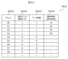
- the buffer management unit 902 also has a management table 902A as shown in FIG. 5C, which holds whether data is stored for each address in the selected data buffer 901, and the time when data was last stored for each address. That is, if the input selected data storage flag 128 is "1", the flag that manages the presence or absence of data is updated to "1", and the update time is recorded by referring to the buffer timer 903.
- 902A1 indicates each address of selected data buffer 901.
- 902A2 is the received selected data storage flag 128, where "1" indicates “store” and “0” indicates “do not store.”
- 902A3 indicates the presence or absence of data, where “1” indicates “data present” and “0” indicates “no data.” Considering situations where data was not written for some reason even though the received selected data storage flag 128 is "1,” selected data storage flag 902A2 and data presence or absence 902A3 are managed separately, but since the two usually match, they may be managed as a single "data presence or absence 902A3.”
- update time 902A4 an arbitrary timing is set as a reference time, and the relative time (elapsed time) at which data was written to the selected data buffer 901 is recorded as a value measured by the buffer timer 903.
- the reference time may be updated using an application update, a system restart, or the like as a trigger.
- the buffer management unit 902 transmits free addresses of the selected data buffer 901 to the address correspondence information generation unit 107 as the selected data storage unit information 124. For example, when the management table 902A has the contents shown in FIG. 5C, "S4, S5, S6, S7, S8, " are transmitted as the selected data storage unit information 124 (free address information).
- the selection data storage unit information 124 may be sent periodically at a predetermined interval, or when a change occurs in an available address. Alternatively, it may be sent in response to a request from the address correspondence information generation unit 107.
- the buffer management unit 902 transmits the presence or absence of unsent data in the selected data buffer 901 to the data transfer determination unit 110 as selected data update information 130 based on the management table 902A. For example, when the management table 902A has the contents shown in FIG. 5C, there is data presence/absence 902A3 with a value of "1", and therefore transmits information indicating that there is unsent data.
- the selected data update information 130 may be sent periodically at a predetermined interval, or when there is a change in the presence or absence of unsent data. Alternatively, it may be sent in response to a request from the data transfer determination unit 110.
- the buffer management unit 902 when the buffer management unit 902 receives a data transfer command 1212 from the data transfer determination unit 110, it transmits to the selected data buffer 901 a "read command 911" for reading unsent data from the selected data buffer 901 and "read address information 911A" for specifying the address to read, based on the management table 902A.
- the address where data presence/absence 902A3 is "1" is the data to be read, and in order to read data with the oldest update time 902A4 (the value with the smallest value), "1" indicating a read instruction is given as "read command 911", and "S0", "S1", “S2”, and “S3” are given as "read address information 911A" to the selected data buffer 901.
- the data recorded in the selected data buffer 901 does not necessarily need to be erased after the read process, as it will be overwritten in a later process.
- 6A is a diagram showing the configuration of the data transfer determination unit 110, which has a transfer determination unit 1202 that determines the timing of data transfer to the CPU 102, and a transfer timer 1203 that outputs time information used to determine the timing of data transmission.
- the transfer timer 1203 transmits, at a set cycle, to the transfer determination unit 1202 a signal that prompts the transfer determination unit 1202 to determine whether or not to transfer, and the current time.
- the transfer decision unit 1202 decides whether or not to transfer the data in the selected data buffer 901 to the CPU 102 based on the selected data update information 130 received from the buffer management unit 902 described above, and if it decides to "transfer,” it sends a data transfer command 1212 to the buffer management unit 902. Note that the transfer timer 1203 may be common to the buffer timer 903.
- FIG. 6B shows the operation flow of the forwarding decision unit 1202.
- the forwarding timer 1203 is set to a time that will be used as a trigger for deciding whether or not to forward (step S1301), and the unit waits until a specified time has elapsed (No in step S1202).
- step S1302 When the specified time has elapsed and a trigger signal is output from the transfer timer (Yes in step S1302), the selected data update information 130 from the buffer management unit 902 is checked (step S1303), and if there is no unsent data in the selected data buffer 901 (No in step S1304), the process returns to the next trigger time set (step S1301). If there is unsent data (Yes in step S1304), a data transfer command is transferred to the buffer management unit 902 (step S1305). As long as the system equipped with this data processing device is not shut down (No in step S1306), the above flow is repeated. If the system is shut down (Yes in step S1306), the process of the transfer determination unit is terminated.
- the arithmetic processing unit (CPU) 102 receives data from the data processing device 103 and performs a predetermined process using the application 104.
- the application 104 has one or more application software programs, each of which has a dedicated data access function built-in, and accesses data from the data processing device 103 and transmits access information 121 that notifies the above-mentioned address correspondence information generating unit 107 of the type of the application software.
- the data processing device 103 selects only the data to be used by the application 104 from the data received from the external device and sends it to the CPU 102, thereby reducing the load on the CPU 102 related to data reception.
- a data processing device according to a second embodiment of the present invention will be described with reference to Figures 7 to 9.
- the difference from the data processing device described in the first embodiment is the configurations and functions of the access information storage unit 300, the received data selection unit 301, and the storage destination determination unit in the address correspondence information generation unit 107 shown in Figure 3A.
- the received data selection unit 301 in the first embodiment compares the information on the destination application extracted from the header information of the received data with the information on the application running in the application 104 to select the data to be sent to the CPU 102, but the received data selection unit 301 in this embodiment compares the information on the sending device extracted from the header information of the received data with the sending device information of the data applied in the application 104 to select the data to be sent to the CPU 102.
- FIG. 7 shows an example of the contents stored in the access information storage unit 300 in this embodiment.
- "device A” and “device D” are stored as source device information 300J of data being applied in the application 104.
- source device 300K of data for which application is currently temporarily suspended, and source device 300L of data that has been applied in the past but is not currently being applied.
- FIG. 8 shows the configuration of selection table 301B in received data selection unit 301 of this embodiment, where application type information 301A2 in selection table 301A shown in FIG. 3C in embodiment 1 has been replaced with source device information 301B2, and information on the data source device ("Device A", "Device B”, etc.) is obtained from the header information, and is recorded sequentially as address 301B1 of received data holding unit 106 where the corresponding data is stored, and source device information 301B2.
- storage destination determination unit 302 is similar to that of Example 1, but instead of determination table 302A shown in FIG. 3D, it has determination table 302B shown in FIG. 9, and received data storage unit address 302B1, source device information 302B2, and application access 302B3 correspond to "received data storage unit address 301B1", “source device information 301B2”, and “application access 301B3" in selection table 301B (FIG. 8), respectively.
- the storage destination determination unit 302 of this embodiment like the received data selection unit 301 described above, links information about the data source device to each address in the selected data storage unit 109 instead of application type information. That is, like in the first embodiment, the storage flag 302B4 of the selected data storage unit is assigned a "1" for data for which the application access 302B3 is "Yes," and the storage address 302B5 of the selected data storage unit is assigned an available address (S0, S1, S2, S3, ...) in the selected data buffer 901 of the selected data storage unit 109.
- the addresses may be assigned in order from the first address of the selected data storage unit to available addresses, or may be grouped together according to the source device or data format.
- application information is used in the first embodiment and source device information is used in the present embodiment to determine whether data is accessed, the determination may be made using both application information and source device information.
- the determination of the relevant data is not limited to application information and source device information, but data format or identification number may also be used.
- the information used for the determination is not limited to one piece of information, but multiple pieces of information may also be used.
- decision table 302B The contents of decision table 302B are sent to data extraction unit 108 as address correspondence information 125, and thereafter, only the data to be used by CPU 102 is sent in the same manner as in Example 1.
- a data processing device will be described with reference to FIG. 10.
- the data required and unnecessary data for the CPU 102 (application 104) may also change accordingly.
- the data stored in the selection data holding unit 109 is transferred to the CPU 102 sequentially at a predetermined timing, if the application is changed while data is being stored in the selection data holding unit 109, the selection data before the change and the selection data after the change are stored in the selection data holding unit 109 in a mixed state, and it is possible that the data required and unnecessary data for the application 104 are sent to the CPU 102 in a mixed state.
- two data processing devices 103 (data processing device #1 (103) and data processing device #2 (103a) are prepared, one of the data processing devices is operated, and before and after changing the application, the operating data processing device is switched to the other data processing device in standby, thereby preventing the mixing of data necessary for the application 104 with data that is not necessary.
- data processing device #1 (103) and data processing device #2 (103a) have basically the same configuration as that shown in the first embodiment (FIG. 1A), and received data 200 is input to both.
- Selector 111 selects either selection data 129a or 129b output from data processing device #1 or #2 (103, 103a) and transfers it to CPU 102 (application 104).
- the control unit 112 outputs a control signal 130 to the selector 111 based on the access information 121 from the application 104, and transfers the access information 121 as is to the data processing device that is in operation, and sends information that "there is no application in operation" (for example, "running application 300A" in Figure 3A corresponds to a blank) as access information to the data processing device that is in standby.
- control unit 112 transfers the access information 121 from the application 104 as access information 121a to data processing device #1 (103) as is, transfers information that "there is no running application” to data processing device #2 (103a), and outputs a control signal 130 to the selector 111 to select the selection data 129a from data processing device #1 (103).
- the control unit 112 transfers the updated access information 121b to the waiting data processing device #2 (103a), and the data extraction unit 108 of the data processing device #2 (103a) starts generating an updated extraction rule (such as the selection table 400 in FIG. 4B) .
- Generation of the extraction rule may also be triggered by various changes in the situation, such as a change in the control target or surrounding environment, or a change in the control state.
- the updated selection data 129b will be output from the data processing device #2 (103a), and the selector 111 switches the data processing device that sends data to the CPU 104 to #2 (103a).
- the decision to update an application may be made by switching as described above each time a new addition, deletion, change, etc. occurs, but since additions, deletions, changes, etc. may occur to different applications within a relatively short period of time, it may be possible to wait until a specified time has elapsed since an application update was detected, or until a specified time has elapsed since new update information has stopped increasing (or the number of updates per hour falls below a certain level).
- the access information 121 may be transferred directly to the standby data processing device #2 (103a) to generate an extraction rule in the data extraction unit 108, and if there is a difference of a certain amount from the previously generated extraction rule, or if there is data that has not been used for a certain amount of time, the extraction rule may be changed to one that deletes unnecessary data that has not been used for a certain amount of time.
- the data processing device is configured in a dual-sided configuration, one of the data processing devices is operated, and before and after changing the application, the operating data processing device is switched to the other standby data processing device, thereby preventing data necessary for the application from being mixed with unnecessary data.
- the selection data storage unit may be duplicated. That is, as shown in FIG. 11, two selection data storage units 109 (selection data storage unit #1 (109) and selection data storage unit #2 (109a) are prepared, and data storage in selection data storage unit #1 (109) and #2 (109a) is switched before and after a change in the application, etc.
- Example 2 when the device starts operating, the same method as in Example 1 is used to write selected data 127 to selected data holding unit 109#1 (109) and control is performed to sequentially read the written data to CPU 102 as transfer data 129a, and transmit the data to CPU 102 via selector 111x as transfer data 129. Meanwhile, data extraction unit 108 transmits control signals 140 and 140A to select data holding unit 109#2 (109a) so that data 127 from data extraction unit 108 is not written. In other words, at that point in time, no data has been written to selected data holding unit 109#2 (109a).
- the change in the application 104 or the like is used as a trigger to stop the transfer of data 129 from the selected data holding unit 109#1 (109) to the CPU 102, and update the extraction rules in the data extraction unit 108 according to the contents of the changed application.
- the subsequent data 127 is written to the selected data holding unit 109#2 (109a) and controlled to be transferred sequentially to the CPU 102 via the selector 111x as transfer data 129b.
- the data transfer decision unit 110 sends a data transfer command 1212a or 1212b to the selected data storage unit #1 (109) or #2 (109a), and outputs a signal 1213 to the selector 111x to select either the selected data storage unit #1 (109) or #2 (109a) that is currently outputting data.
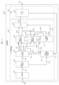
- the data processing device 103 is placed in a relay device 1801 separate from the control device 101 in which the CPU 102 is mounted.
- the data processing device 103 extracts data to be used by the CPU 102 from the data sent from the sending device 1802 and sends it to the control device 101.
- a more flexible and efficient configuration can be adopted for expanding the system, such as adopting a configuration in which a single relay device 1801 extracts transmission data for multiple control devices 101.
- control device in each of the above embodiments can use a wired or wirelessly connected computer, tablet device, etc. to perform various settings and monitor various information during operation.
- FIGS. 13A to 13E are examples of display screens on such personal computers or terminals.
- the operator presses the Various Settings button 1301 to configure various settings, or the Monitoring button 1302 to monitor the device.
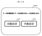
- FIG. 13B is an example screen for setting rules for selecting data in the data processing device.
- Pressing the automatic setting button 1303 automatically sets the selection rules by receiving information on the type of application currently in operation from the application 104, as described in Example 1 and the like.
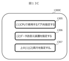
- Pressing the manual setting button 1304 here displays a selection rule specification method selection screen 1300C shown in FIG. 13C, and for example, selecting "(1) Specify the application to be used by the CPU” 1305 displays an input window (not shown) that allows the operator to input application type information.
- the "currently in operation application 300A" shown in FIG. 3B is manually set (input).
- pressing the monitoring button 1302 displays the display content selection screen 1300D shown in Fig. 13D.
- pressing the buttons for the amount of data received by the data processing device 1308, the amount of data transferred to the CPU 1309, and the CPU load factor 1310 the respective values can be confirmed.
- a screen 1300E as shown in FIG. 13E is displayed, where 1300E1 shows the amount of data received in the most recent period (1 hour, 6 hours, 12 hours) in terms of the number of bytes and the number of packets (pct). 1300E2 shows the change over time in a graph. Note that the amount of data transferred to the CPU 1309 and the CPU load factor 1310 can also be displayed in a similar manner.
- the receiving unit 105 and selected data storage unit of the data processing device 103 have a function for monitoring the amount and attributes of the data to be output, and the CPU 102 also has a function for monitoring the load factor of its operation, and these functions can be used to display the results on the screen.
- Control device 102 CPU 103: Data processing device 104: Application 105: Receiving unit 106: Received data holding unit 107: Address correspondence information generating unit 108: Data extraction unit 109: Selected data holding unit 110: Data transfer determination unit
Landscapes
- Engineering & Computer Science (AREA)
- Theoretical Computer Science (AREA)
- Physics & Mathematics (AREA)
- General Engineering & Computer Science (AREA)
- General Physics & Mathematics (AREA)
- Quality & Reliability (AREA)
- Information Retrieval, Db Structures And Fs Structures Therefor (AREA)
Applications Claiming Priority (2)
| Application Number | Priority Date | Filing Date | Title |
|---|---|---|---|
| JP2023-181517 | 2023-10-23 | ||
| JP2023181517A JP2025071397A (ja) | 2023-10-23 | 2023-10-23 | 制御装置、制御システム、および制御方法 |
Publications (1)
| Publication Number | Publication Date |
|---|---|
| WO2025088877A1 true WO2025088877A1 (ja) | 2025-05-01 |
Family
ID=95515631
Family Applications (1)
| Application Number | Title | Priority Date | Filing Date |
|---|---|---|---|
| PCT/JP2024/029069 Pending WO2025088877A1 (ja) | 2023-10-23 | 2024-08-15 | 制御装置、制御システム、および制御方法 |
Country Status (2)
| Country | Link |
|---|---|
| JP (1) | JP2025071397A (https=) |
| WO (1) | WO2025088877A1 (https=) |
Citations (2)
| Publication number | Priority date | Publication date | Assignee | Title |
|---|---|---|---|---|
| JP2014191589A (ja) * | 2013-03-27 | 2014-10-06 | Hitachi Ltd | 情報処理システム及び情報処理システムの制御方法 |
| JP2023066974A (ja) * | 2021-10-29 | 2023-05-16 | サイレックス・テクノロジー株式会社 | 中継装置およびその方法、ならびにプログラム |
-
2023
- 2023-10-23 JP JP2023181517A patent/JP2025071397A/ja active Pending
-
2024
- 2024-08-15 WO PCT/JP2024/029069 patent/WO2025088877A1/ja active Pending
Patent Citations (2)
| Publication number | Priority date | Publication date | Assignee | Title |
|---|---|---|---|---|
| JP2014191589A (ja) * | 2013-03-27 | 2014-10-06 | Hitachi Ltd | 情報処理システム及び情報処理システムの制御方法 |
| JP2023066974A (ja) * | 2021-10-29 | 2023-05-16 | サイレックス・テクノロジー株式会社 | 中継装置およびその方法、ならびにプログラム |
Also Published As
| Publication number | Publication date |
|---|---|
| JP2025071397A (ja) | 2025-05-08 |
Similar Documents
| Publication | Publication Date | Title |
|---|---|---|
| CN112416641A (zh) | 主从架构中被控端节点重启检测方法及主控端节点 | |
| JP6201298B2 (ja) | コントローラおよびプログラム | |
| JP2000511675A (ja) | ソフトウェアシステム間でソフトウェア機能を同期化させるための方法および装置 | |
| US6668205B1 (en) | Control method of factory automation system, recording medium recording a program therefor and central processor of factory automation system | |
| WO2025088877A1 (ja) | 制御装置、制御システム、および制御方法 | |
| JP2006244415A (ja) | データ制御装置 | |
| JP2001051871A (ja) | リモートデバッグ装置 | |
| US8547985B2 (en) | Network interface controller capable of sharing buffers and buffer sharing method | |
| JP2014197346A (ja) | コントローラおよびプログラム | |
| JP6141542B2 (ja) | 制御システム | |
| CN114051047A (zh) | 一种会话消息的备份方法、装置、网络设备和存储介质 | |
| CN111625385B (zh) | 调整rpm来处理死机的方法、系统、终端设备及存储介质 | |
| JP2007219843A (ja) | ノード管理装置及びノード管理方法及びプログラム | |
| JP2009032241A (ja) | 計算機システム及び計算機制御方法,制御プログラムを格納した記憶媒体 | |
| JP2006005719A (ja) | アドレス変換プログラム、プログラム利用方法、情報処理装置及びコンピュータ可読媒体 | |
| CN112422692A (zh) | 一种网络请求方法及相关装置 | |
| JP2010108202A (ja) | 機器監視制御システム、機器監視制御方法、及び制御プログラム | |
| JP2003229859A (ja) | ネットワークシステムにおけるデータ制御装置 | |
| CN119003390A (zh) | 一种设备控制方法、处理器架构以及计算机设备 | |
| CN119003389A (zh) | 一种设备控制方法、处理器架构以及计算机设备 | |
| JP2001251318A (ja) | ゲートウェイシステム及び情報端末 | |
| JP2023028375A (ja) | 情報処理装置、情報処理方法、プログラム、及びシステム | |
| CN114328740A (zh) | 一种跨机房数据库同步方法和装置 | |
| CN117632766A (zh) | 测试环境的配置方法、装置、电子设备和存储介质 | |
| JPH03113503A (ja) | 産業用コンピュータ |
Legal Events
| Date | Code | Title | Description |
|---|---|---|---|
| 121 | Ep: the epo has been informed by wipo that ep was designated in this application |
Ref document number: 24881994 Country of ref document: EP Kind code of ref document: A1 |