WO2025088694A1 - 疑似障害物運搬装置 - Google Patents
疑似障害物運搬装置 Download PDFInfo
- Publication number
- WO2025088694A1 WO2025088694A1 PCT/JP2023/038348 JP2023038348W WO2025088694A1 WO 2025088694 A1 WO2025088694 A1 WO 2025088694A1 JP 2023038348 W JP2023038348 W JP 2023038348W WO 2025088694 A1 WO2025088694 A1 WO 2025088694A1
- Authority
- WO
- WIPO (PCT)
- Prior art keywords
- wheel
- steering
- obstacle
- connection mechanism
- transport device
- Prior art date
- Legal status (The legal status is an assumption and is not a legal conclusion. Google has not performed a legal analysis and makes no representation as to the accuracy of the status listed.)
- Ceased
Links
Images


Classifications
-
- G—PHYSICS
- G01—MEASURING; TESTING
- G01M—TESTING STATIC OR DYNAMIC BALANCE OF MACHINES OR STRUCTURES; TESTING OF STRUCTURES OR APPARATUS, NOT OTHERWISE PROVIDED FOR
- G01M17/00—Testing of vehicles
- G01M17/007—Wheeled or endless-tracked vehicles
-
- G—PHYSICS
- G01—MEASURING; TESTING
- G01M—TESTING STATIC OR DYNAMIC BALANCE OF MACHINES OR STRUCTURES; TESTING OF STRUCTURES OR APPARATUS, NOT OTHERWISE PROVIDED FOR
- G01M7/00—Vibration-testing of structures; Shock-testing of structures
- G01M7/08—Shock-testing
Definitions
- the present invention relates to a simulated obstacle transport device for use in automobile performance testing.
- performance tests are conducted by simulating specific collision conditions to evaluate the degree of collision avoidance and damage reduction.
- This performance test is conducted using the automobile to be evaluated and a simulated obstacle transport device (hereinafter abbreviated as the transport device) (see, for example, Patent Document 1).
- the transport device runs while loaded with simulated obstacles (for example, dummies that simulate various obstacles such as people and bicycles) used in automobile performance tests, reproducing the movements of various obstacles.
- simulated obstacles for example, dummies that simulate various obstacles such as people and bicycles
- the transport device may be run over by the wheels of the automobile when the automobile collides with a simulated obstacle. When this happens, the transport device is dragged by the automobile, and this dragging exerts an external force on the steering wheel, centered on the steering shaft, which may damage the power unit that drives the steering wheel.
- the object of the present invention is to provide a pseudo obstacle transport device that can reduce the external force applied to the steering wheel when it comes into contact with an automobile, thereby minimizing damage to the steering wheel.
- the present invention provides a pseudo obstacle transport device that travels with a pseudo obstacle loaded on it, the device having a steering wheel that controls the direction of travel, a housing that covers the steering wheel, and a steering power unit that is connected to the housing and applies an external force to the steering wheel to change the direction of travel, the steering wheel being configured to contact the ground on an extension of its steering axis.
- the present invention can reduce the external force applied to the steering wheel when it comes into contact with the vehicle, thereby minimizing damage to the steering wheel.
- 1 is a perspective view showing an external configuration of a pseudo obstacle transportation device according to an embodiment of the present invention
- 1 is a bottom view showing the external configuration of a pseudo obstacle transportation device according to an embodiment of the present invention
- 1 is an exploded view of a housing and a traveling device of a pseudo obstacle transportation device according to an embodiment of the present invention.
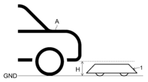
- 1 is a diagram showing the height relationship between the overall height of a simulated obstacle transporting device according to one embodiment of the present invention and the ground clearance of a test subject automobile.
- 1 is a schematic diagram showing an operation form of a pseudo obstacle transportation device according to an embodiment of the present invention
- 1 is a schematic diagram showing an operation form of a pseudo obstacle transportation device according to an embodiment of the present invention
- 1 is a schematic diagram showing an operation form of a pseudo obstacle transportation device according to an embodiment of the present invention
- 1 is a schematic diagram showing an operation form of a pseudo obstacle transportation device according to an embodiment of the present invention
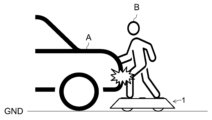
- 1 is a schematic diagram showing a performance test of an automobile using a simulated obstacle transportation device according to an embodiment of the present invention
- 2 is a perspective view of a steering wheel provided on the pseudo obstacle transportation device according to one embodiment of the present invention
- FIG. FIG. 7 is a rear view of the steering wheel as viewed in the direction of arrow VII in FIG. 6 .
- FIG. 8 is a cross-sectional view taken along line VIII-VIII in FIG. 9, seen in the same direction as FIG. 7.
- 9 is a cross-sectional view taken along line IX-IX in FIG. 8 .
- 2 is a plan view of a steering wheel provided on a pseudo obstacle transportation device according to an embodiment of the present invention.
- FIG. 11 is a cross-sectional view taken along line XIb-XIb in FIG. 9 of XIa in FIG. 10 . 2 is a bottom view of a steering wheel provided on the pseudo obstacle transportation device according to one embodiment of the present invention.
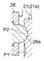
- FIG. 11 is an enlarged cross-sectional view of part XIIIa of FIG. 9 taken along line XIIIb-XIIIb in FIG. 10.
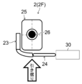
- FIG. 11 is an explanatory diagram of the effect of one embodiment of the present invention.
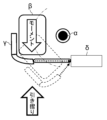
- FIG. 13 is an explanatory diagram of a problem in a comparative example.
- Fig. 1 is a perspective view showing the external configuration of a simulated obstacle transporting device according to one embodiment of the present invention
- Fig. 2A is a bottom view thereof
- Fig. 2B is an exploded view thereof
- Fig. 3 is a diagram showing the height relationship between the overall height of the simulated obstacle transporting device shown in Fig. 1 and the minimum ground clearance of a test subject automobile
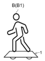
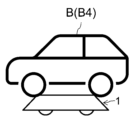
- Figs. 4A to 4D are schematic diagrams showing the operating form of the simulated obstacle transporting device.
- the right, left, bottom, and top of Fig. 2A correspond to the front, rear, left, and right of the simulated obstacle transporting device 1 (hereinafter abbreviated as transporting device 1) of this embodiment.
- the transport device 1 shown in FIG. 1 is a device that stops or runs with a pseudo obstacle B, which is a dummy obstacle used in a performance test of an automobile (test vehicle) A, loaded on it, simulating a static or dynamic obstacle.
- the body of the pseudo obstacle B is generally made of a soft material such as a balloon, so that even if the automobile A collides with the pseudo obstacle B during a performance test, the pseudo obstacle B and the automobile A are unlikely to be damaged.
- the functions of the AD (Autonomous Driving) and ADAS (Advanced Driver-Assistance Systems) of the automobile A are tested.
- the transport device 1 is configured to be low-profile and thin so that it is unlikely to be recognized as an obstacle by the external recognition sensor of the automobile A to be tested, and to avoid contact with the body of the automobile A when the automobile A collides with the pseudo obstacle B. As shown in FIG. 3, the overall height of the transport device 1 from the ground surface is lower than the minimum ground clearance H of the automobile A, for example, about 100 mm.
- the components of the transport device 1 include a running device 2 (Fig. 2A), a housing 3, and connection parts 4 and 5.
- the traveling device 2 is a device that allows the transport device 1 to travel under its own power, and the transport device 1 is equipped with multiple (three in this embodiment) traveling devices (drive wheels 2L, 2R and steering wheels 2F. Each of these drive wheels 2L, 2R and steering wheels 2F includes one wheel 25.
- the transport device 1 of this embodiment is configured to perform braking only by regenerating the drive motors of the drive wheels 2L and 2R, and is compact by omitting mechanical brakes.
- the transport device 1 also omits a suspension mechanism in anticipation of travel on paved surfaces such as test courses, thereby further miniaturizing the device. However, it is possible to install mechanical brakes or suspension mechanisms as necessary.
- the steering wheel 2F is a driven wheel (or may be a driving wheel) that controls the traveling direction of the transport device 1, and is located in the front center of the housing 3.
- the driving wheel 2L is located on the left rear of the left housing 3, and the driving wheel 2R is located on the right rear of the housing 3.
- the driving wheels 2L and 2R are located in the rear corners of the main body 3a of the housing 3, and the steering wheel 2F is located near the front inner wall of the main body 3a of the housing 3. In this way, the wheelbase and tread are maximized in the limited space inside the main body 3a of the housing 3, improving straight-line stability.
- the transport device 1 is driven to travel by the driving wheels 2L and 2R, which are the rear wheels, and steered by the steering wheel 2F, which is the front wheel.
- the driving wheels 2L and 2R which are the rear wheels
- the steering wheel 2F which is the front wheel.
- an area X for mounting relatively heavy control devices is provided in the triangular area S surrounded by the drive wheels 2L, 2R and steering wheel 2F.
- left and right areas Y for mounting batteries and left and right areas Z for mounting other electronic devices are arranged on either side of area X and the steering wheel 2F.
- the transport device 1 is a three-wheeled vehicle that runs on a total of three wheels 25, the steering wheel 2F and the drive wheels 2L, 2R, and the three wheels 25, spaced apart in three places, are always in contact with the ground, eliminating the need for a height adjustment mechanism for the wheels 25.
- the housing 3 is the body of the transport device 1, has connection parts 4 and 5 that connect the dummy obstacle B, and covers the traveling device 2.
- the housing 3 is configured to include a main body part 3a (core block) and a slope part 3b (cover).
- the housing 3 can be configured as an assembly of the main body part 3a and the slope part 3b, with the main body part 3a and the slope part 3b being separate structures, or the main body part 3a and the slope part 3b can be configured as a single unit molded structure.
- the main body 3a has a thin box-like shape that is rectangular (square in the example shown) in plan view, has front, rear, left and right sides and a top surface, and is open on the bottom.
- the top surface (top surface) of the main body 3a is a horizontal plane, but this is not necessarily the case.
- the main body 3a is made of metal and has high strength to withstand the load even if it is run over by the automobile A.
- ribs can be provided appropriately inside the main body 3a (the volumetric space surrounded by the front, rear, left and right sides and the top surface) to improve the strength of the main body 3a.
- the sloped surface 3b is located on the outer periphery of the main body 3a and surrounds the entire circumference of the main body 3a.
- the sloped surface 3b is detachably attached to the front, back, left and right of the main body 3a.
- the upward surface of the sloped surface 3b is a sloped surface that slopes downward from the horizontal center of the housing 3 toward the outside, and descends from the upper surface of the main body 3a toward the ground surface.
- the inclination angle, etc. of this sloped surface is set so that the wheels of the car A can smoothly ride up onto the transport device 1 when the car A collides with the simulated obstacle B.
- the sloped surface 3b is a replaceable part and is made of lightweight resin.
- Figure 2A shows an example of a structure in which the sloped surface 3b has been hollowed out to reduce weight.
- the connection part 4 is a mechanism for fixing the pseudo obstacle B to the housing 3, and is provided at the top of the housing 3, for example, at the center of the top surface.
- the configuration of the connection part 4 is appropriately adopted according to the mechanism for attaching and detaching the pseudo obstacle B to the transport device 1.
- the connection part 4 illustrated in FIG. 1 is a mechanism like a clamp that holds down the base plate of a pole (pipe, etc.).
- the pseudo obstacle B is fixed to the transport device 1 by attaching it to a pole supported by the connection part 4 or by fastening the pseudo obstacle to the pole.
- the connection part 4 can be configured with a screw hole into which a bolt for fixing the pseudo obstacle B is screwed, and the configuration of the connection part 4 can be variously changed in design.
- connection part 5 uses a magnet and fixes the pseudo obstacle B by attracting an iron plate provided at the bottom of the pseudo obstacle B. It is not necessary to provide both the connection parts 4 and 5, and either one may be omitted. In addition, the layout of the connection parts 4 and 5 can also be changed as appropriate.
- the dummy obstacle B is attached to the top of the housing 3 of the transport device 1 via these connections 4 and 5, and the transport device 1 travels in this state, causing the transport device 1 to reproduce the movement of the obstacle that the dummy obstacle B imitates.
- the dummy obstacle B is selected in a shape appropriate for the purpose of the performance test and attached to the transport device 1.
- Figure 4A shows an example in which a dummy obstacle B simulating a pedestrian B1 is mounted on the transport device 1.
- Figure 4B shows an example in which a bicycle B2 is mounted on the transport device 1
- Figure 4C shows an example in which a motorcycle B3 is mounted on the transport device 1
- Figure 4D shows an example in which a car B4 is mounted on the transport device 1.
- the transport device 1 travels in response to, for example, a radio signal in response to an operator's remote control operation, a radio signal remotely controlled by a control device, or a predefined program, and reproduces the specified movement of the loaded dummy obstacle B.
- Figure 5 is a schematic diagram showing a performance test of automobile A using a transport device 1.
- the transport device 1 loaded with a simulated obstacle B stops or runs under the test conditions specified in the performance test.
- the automobile A being tested runs relative to the simulated obstacle B loaded on the transport device 1, recognizing the simulated obstacle B as a real obstacle using its obstacle recognition function, and activating collision avoidance functions, etc. as necessary. If the test conditions make it difficult to avoid a collision with the simulated obstacle B, the body of automobile A will collide with the simulated obstacle B as shown in Figure 5.
- Participants in the performance test observe the collision situation between automobile A and simulated obstacle B from a location that is an appropriate distance away from automobile A and the transport device 1.
- Fig. 6 is a perspective view of the steered wheel 2F
- Fig. 7 is a rear view of the steered wheel 2F as seen in the direction of the arrow VII in Fig. 6
- Fig. 8 is a view seen in the same direction as Fig. 7 and is a cross-sectional view taken along line VIII-VIII in Fig. 9, and
- Fig. 9 is a cross-sectional view taken along line IX-IX in Fig. 8.
- Fig. 10 is a plan view of the steered wheel 2F
- Fig. 11 is a cross-sectional view taken along line XIb-XIb in Fig. 9 of XIa in Fig. 10
- Fig. 12 is a bottom view of the steered wheel 2F
- Fig. 13 is an enlarged cross-sectional view taken along line XIIIb-XIIIb in Fig. 10 of part XIIIa in Fig. 9.
- the steering wheel 2F is composed of a wheel 25, a steering shaft (kingpin) 26, a first connection mechanism 21, a second connection mechanism 22, a third connection mechanism 23, and a fourth connection mechanism 24.
- the wheel 25 is composed of a cylindrical wheel 25a and a tire 25b that covers the outer circumferential surface of the wheel 25a and comes into contact with the ground.
- the outer circumferential surface of the tire 25b forms a curved surface that is convex outward in a cross section cut by a plane passing through the rotation center line C1 of the wheel 25 as shown in FIG. 8.
- the steered wheel 2F has a convex ground contact surface, and the ground contact area is reduced compared to when the outer circumferential surface of the tire 25b is cylindrical.
- the ground contact portion 25c of the tire 25b is located on the center line C2 of the steering shaft 26, and the steered wheel 2F is configured to come into contact with the ground on the extension of the steering shaft 26.
- the center line C2 of the steering shaft 26 may pass through the ground contact portion 25c that has an area, but it is preferable that it passes through the ground contact center (the center point of the ground contact portion 25c) of the steered wheel 2F.
- the steering shaft (kingpin) 26 is housed inside the cylindrical wheel 25a of the steered wheel 2F.
- the steering shaft (kingpin) is placed away from the center of the tire to accommodate brake rotors, etc., but in this embodiment, the steering shaft 26 is placed inside the wheel 25a of the steered wheel 2F.
- the steering shaft 26 extends vertically, and the center line C2 of the steering shaft 26 is perpendicular to the ground with which the steered wheel 2F contacts the ground at the ground contact portion 25c of the steered wheel 2F. In this way, the steered wheel 2F is configured so that the caster angle and caster trail are zero.
- the caster angle is the angle between the ground contact center axis (a line perpendicular to the ground contact surface) of the steered wheel 2F and the steering shaft, and as described above, the center line C2 of the steering shaft 26 corresponds to the ground contact center axis of the steered wheel 2F, so the caster angle is zero degrees.
- Caster trail is the distance from the intersection of the extension of the steering shaft 26 and the ground to the ground contact part 25c of the steering wheel 2F, and as mentioned above, the steering wheel 2F touches the ground on the extension of the steering shaft 26, so the caster trail is 0 mm.
- the first connection mechanism 21 connects the steering shaft 26 and the housing 3.
- the first connection mechanism 21 is composed of a base 21a and an arm portion 21b as shown in FIG. 11.
- the base 21a and the arm portion 21b are formed integrally.
- the arm portion 21b extends along the rotation center line C1 of the wheels 25 when the transport device 1 is in a straight-ahead position, and supports the steering shaft 26 at its tip portion inserted inside the wheel 25a of the wheels 25.
- the cross section of the arm portion 21b cut perpendicular to the rotation center line C1 is long vertically, and has a shape that becomes thinner (thinner) from the steering shaft 26 toward the sliding mechanism 27, i.e., toward the base 21a, in a plan view as shown in FIG. 11.
- the base 21a of the first connection mechanism 21 is connected to the housing 3 via a sliding mechanism 27 (linear guide) and can slide perpendicular to the contact surface of the steering wheel 2F, i.e., vertically. In other words, the wheel 25 supported by the first connection mechanism 21 can move upward relative to the housing 3 along with the first connection mechanism 21.
- the sliding mechanism 27 includes a rail 27a and a block 27b.
- the rail 27a is fixed to the housing 3, and the block 27b slides up and down while being guided by the rail 27a.
- the first connection mechanism 21 moves relative to the housing 3 by being fixed to this block 27b.
- the steering wheel 2F is selectively held by the position fixing mechanism 28 at a first fixing part P1 or a second fixing part P2 ( Figure 13) which are different in height.
- the position fixing mechanism 28 is a plunger fixed to the housing 3, and the first fixing part P1 or the second fixing part P2 is a recess provided in the first connection mechanism 21 or the block 27b of the sliding mechanism 27.
- the pin (or ball) 28a at the tip of the position fixing mechanism 28 fits into the first fixing part P1 or the second fixing part P2, so that the steering wheel 2F is held by the first fixing part P1 or the second fixing part P2.
- the steering wheel 2F is held by the first fixing part P1 and the wheel 25 partially protrudes below the housing 3, but if an external force acts on the housing 3, such as when the car A runs over the housing 3, the pin 28a comes off the first fixing part P1 and the steering wheel 2F (wheel 25) moves upward relative to the housing 3, and the pin 28a fits into the second fixing part P2, with the steering wheel 2F completely stored in the housing 3.
- a similar mechanism is also provided separately in the transport device 1 for the drive wheels 2L and 2R.
- the jig J shown in Figure 6 etc. is inserted from above the housing 3 through the through hole 3e ( Figure 1) of the housing 3 when the steering wheel 2F is fixed at the second fixing part P2, and pushes down the steering wheel 2F (here, the base part 21a of the first connection mechanism 21), returning the steering wheel 2F to a state where it is held at the first fixing part P1.
- the upper limit of the movement range of the steering wheel 2F relative to the housing 3 is limited by a stopper 29 fixed to the housing 3, and is configured so that the steering wheel 2F does not rise beyond the second fixing part P2.
- the second connection mechanism 22 connects the steering shaft 26 and the steering power unit 30.
- the steering power unit 30 is a power unit, such as a servo motor, that applies an external force to the steering wheel 2F to change the traveling direction of the transport device 1, and is connected and fixed to the housing 3.
- this second connection mechanism is composed of a wheel unit 22a that connects to the wheel 25a of the steering wheel 2F, a wheel axle 22b that connects to the steering shaft 26, and a bearing unit 22c that connects the wheel unit 22a and the wheel axle 22b.
- the wheel portion 22a is a cylindrical member, and as shown in FIG. 8, is integrally formed (as one part) with the wheel 25a of the wheel 25, and protrudes from the wheel 25 on the opposite side to the first connection mechanism 21 across the steering shaft 26.
- the wheel axle 22b extends along the rotation center line C1 of the wheel 25, is inserted into the inside of the wheel 25a of the wheel 25 from the opposite side to the arm portion 21b of the first connection mechanism 21, and is connected to the steering shaft 26 via the bearing 22d so as to be freely rotatable in the horizontal direction.
- the wheel axle 22b of the second connection mechanism 22 is connected to the steering shaft 26 located inside the wheel 25a of the wheel 25 from the opposite side to the first connection mechanism 21 across the steering shaft 26.
- the bearing portion 22c is a hub bearing arranged on the outside of the wheel 25, and connects the wheel portion 22a to the wheel axle 22b so as to be freely rotatable around the rotation center line C1. This allows the wheel 25 to rotate freely relative to the wheel axle 22b.
- the bearing portion 22c which is a hub bearing, on the outside of the wheel 25, space is secured inside the wheel 25 to place the steering shaft 26.
- the second connection mechanism 22 is not directly connected to the steering power unit 30, but is connected to the steering power unit 30 via the third connection mechanism 23 and the fourth connection mechanism 24.
- the third connection mechanism 23 is a knuckle arm that connects the second connection mechanism 22 and the fourth connection mechanism 24.
- the third connection mechanism 23 has a screw portion that is fixed to the wheel axle 22b of the second connection mechanism 22 by this screw portion ( Figure 8).
- the fourth connection mechanism 24 connects the third connection mechanism 23 and the steering power unit 30 and is configured to be tiltable.
- the fourth connection mechanism 24 is configured to include a link shaft 24a and a rod end bearing 24b.
- the link shaft 24a is fixed to the output shaft of the steering power unit 30.
- the rod end bearing 24b is rotatably connected at one end to the end of the link shaft 24a and at the other end to the end of the third connection mechanism 23 via a ball joint.
- the third connection mechanism 23 moves to the upper limit relative to the link shaft 24a, the rod end bearing 24b tilts up and down.
- the vertical movement of the steering wheel 27 caused by the sliding mechanism 27 (movement between the first fixed part P1 and the second fixed part P2) is absorbed by the tilt of the rod end bearing 24b and is not transmitted to the steering power part 30.
- the steering wheel 2F is configured to come into contact with the ground on the extension of the steering shaft 26, and the scrub radius is essentially zero.
- the transport device 1 interferes with the automobile A and is dragged, there is a point of action (grounding point) on the extension of the steering shaft 26, which serves as the moment center, where an external force acts on the steering wheel 2F due to the drag, so the moment acting on the steering wheel 2F around the steering shaft 26 can be suppressed.
- This makes it possible to suppress the application of an external force from the steering wheel 2F to the steering power unit 30, and to suppress damage to the steering power unit 30.
- the steering shaft 26 is arranged inside the wheel 25a of the steered wheel 2F, and the first connection mechanism 21 and the second connection mechanism 22 are connected to the steering shaft 26 from opposite sides, and the steering shaft 26 is connected to the housing 3 via the first connection mechanism 21, and the steering shaft 26 is connected to the steering power unit 30 via the second connection mechanism 22.
- the steering power unit 30 is fixed to the housing 3. In this way, the steering power unit 30 is fixed to the housing 3 and is not an object to be rotated, so the steering mechanism can be made smaller than in a configuration in which the steering wheel 2F is rotated together with the steering power unit 30. Furthermore, the size and weight of the object to be rotated can be kept small, and the size of the steering power unit 30 can also be reduced.
- the first connection mechanism 21 is connected to the housing 3 via the sliding mechanism 27, and the steering wheel 2F can move vertically.
- the steering wheel 2F is stored in the housing 3, and damage to the steering wheel 2F can be suppressed.
- the second connection mechanism 22 is configured to have a wheel portion 22a that connects to the wheel 25a of the steering wheel 2F, a wheel axle 22b that connects to the steering shaft 26, and a bearing portion 22c that connects the wheel portion 22a and the wheel axle 22b.
- the required values of power performance (acceleration and maximum speed) required for the transport device 1 in a performance test to evaluate the collision safety of the automobile A can be achieved without driving the steering wheel 2F. Therefore, in this embodiment, the steering wheel 2F is a driven wheel, and the bearing portion 22c as a hub bearing is arranged outside the wheel 25a to allow the steering wheel 2F to rotate freely in the traveling direction.
- the bearing portion 22c as a hub bearing outside the wheel 25a, space can be secured inside the wheel 25a, and the steering shaft 26 can be arranged inside the wheel 25a.
- the steering wheel 2F In order to steer the steering wheel 2F, it is necessary for the steering wheel 2F to be connected to the steering power unit 30. At the same time, the steering wheel 2F needs to be configured to be movable in the vertical direction so that the steering wheel 2F can be stored in the housing 3 when the automobile A runs onto the transport device 1, for example.
- the second connection mechanism 22 is connected to the steering power unit 30 via the third connection mechanism 23 and the fourth connection mechanism 24, and the fourth connection mechanism 24 is configured to be tiltable. This allows the vertical movement of the steered wheels 2F to be absorbed by the tilting of the fourth connection mechanism 24, and prevents the external force caused by the vertical movement of the steered wheels 2F from being transmitted and damaging the steering power unit 30.
- the steering angle of the steering wheel 2F can be increased compared to the case where the arm portion 21b is made of a uniform thickness.
- the maximum steering angle is restricted by interference between the arm portion 21b and the wheel 25a.
- the arm portion 21a becomes thinner as it moves away from the steering shaft 26, so the necessary steering angle can be ensured. This ensures sufficient maneuverability of the transport device 1.
- the steering wheel 2F is configured so that the caster angle and caster trail are zero. In a manned aircraft, if the caster angle or caster trail is zero, the maneuverability becomes too sensitive and straight-line stability cannot be maintained. However, since the transport device 1 is an unmanned aircraft, the caster angle and caster trail can be set to zero, improving the agility of the transport device 1.
- the position fixing mechanism 28 is a ball plunger, and the traveling device 2 is fixed to either the first fixing part P1 or the second fixing part P2 by the spring force of the ball plunger.
- the fact that the position fixing mechanism 28 can be easily configured using a ball plunger, which is a general-purpose equipment element, can also contribute to making the transport device 1 smaller and less expensive.
- the transport device 1 is a three-wheeled vehicle, the three wheels 25 naturally come into contact with the ground at the same time. This makes it possible to eliminate the need for a position adjustment mechanism for the wheels 25 or a suspension mechanism.
- the road surface on which the transport device 1 runs is expected to be a paved test course or the like, so the absence of a suspension mechanism does not pose any particular problem, and eliminating the suspension mechanism and the position adjustment mechanism for the wheels 25 offers significant benefits, such as space savings, compactness, weight reduction, reduced number of parts, and easier maintenance.
- 1...dummy obstacle transport device 2F...steering wheel, 3...housing, 25a...wheel, 26...steering shaft, 21...first connection mechanism, 22...second connection mechanism, 22a...wheel section, 22b...wheel shaft, 22c...bearing section, 23...third connection mechanism, 24...fourth connection mechanism, 30...steering power section, 27...sliding mechanism, B...dummy obstacle
Landscapes
- Physics & Mathematics (AREA)
- General Physics & Mathematics (AREA)
- Handcart (AREA)
Abstract
疑似障害物を積載して走行する疑似障害物運搬装置であって、走行方向を操作する操舵輪と、前記操舵輪を覆う筐体と、前記筐体に接続し、前記操舵輪に外力を与えて前記走行方向を変更する操舵動力部と、を有し、前記操舵輪は、その操舵軸の延長上で接地するように構成されている障害物運搬装置を提供する。前記操舵輪は、ホイールの内部に前記操舵軸を収納しており、前記操舵軸及び前記筐体を接続する第1の接続機構と、前記操舵軸及び前記操舵動力部を接続する第2の接続機構とを備え、前記第2の接続機構が、前記ホイールの内部に位置する前記操舵軸に対し、前記操舵軸を挟んで前記第1の接続機構と反対側から接続している。
Description
本発明は、自動車の性能試験に用いる疑似障害物運搬装置に関する。
自動車の障害物の認識性能や回避性能を客観的に評価するために、所定の衝突条件を模擬して性能試験を行い、衝突の回避や被害低減の度合いを評価することが行われる。この性能試験は、評価対象である自動車と、疑似障害物運搬装置(以下、運搬装置と略記する)とを使用して行われる(例えば特許文献1)。運搬装置は、自動車の性能試験に用いる疑似障害物(例えば人や自転車といった各種障害物を模擬したダミー)を積載した状態で走行し、各種障害物の動きを再現する。運搬装置を用いた再現性の高い性能試験を行うことにより、自動車の衝突安全性が精度良く評価される。
自動車の性能実験において、運搬装置は、自動車と疑似障害物が衝突した際、自動車の車輪に踏み付けられることがある。その際、運搬装置は自動車に引き摺られ、この引き摺りにより操舵輪に操舵軸を中心とするモーメントが外力として加わり、操舵輪を駆動する動力部が損傷する可能性がある。
本発明の目的は、自動車との干渉時に操舵輪に加わる外力を低減し操舵輪の損傷を抑制することができる疑似障害物運搬装置を提供することにある。
上記目的を達成するために、本発明は、疑似障害物を積載して走行する疑似障害物運搬装置であって、走行方向を操作する操舵輪と、前記操舵輪を覆う筐体と、前記筐体に接続し、前記操舵輪に外力を与えて前記走行方向を変更する操舵動力部とを有し、前記操舵輪は、その操舵軸の延長上で接地するように構成されている障害物運搬装置を提供する。
本発明によれば、自動車との干渉時に操舵輪に加わる外力を低減し操舵輪の損傷を抑制することができる。
以下に図面を用いて本発明の実施の形態を説明する。
-疑似障害物運搬装置-
図1は本発明の一実施形態に係る疑似障害物運搬装置の外観構成を表す斜視図、図2Aはその下面図、図2Bは分解図である。また、図3は図1に示した疑似障害物運搬装置の全高と試験対象の自動車の最低地上高との高さ関係を示す図、図4A-図4Dは疑似障害物運搬装置の運用形態を表す模式図である。図2Aの右・左・下・上を、本実施形態の疑似障害物運搬装置1(以下、運搬装置1と略記する)の前・後・左・右とする。
図1は本発明の一実施形態に係る疑似障害物運搬装置の外観構成を表す斜視図、図2Aはその下面図、図2Bは分解図である。また、図3は図1に示した疑似障害物運搬装置の全高と試験対象の自動車の最低地上高との高さ関係を示す図、図4A-図4Dは疑似障害物運搬装置の運用形態を表す模式図である。図2Aの右・左・下・上を、本実施形態の疑似障害物運搬装置1(以下、運搬装置1と略記する)の前・後・左・右とする。
図1等に示した運搬装置1は、自動車(テスト車両)Aの性能試験に用いるダミー障害物である疑似障害物Bを積載して停止又は走行し、静的又は動的な障害物を模擬する装置である。疑似障害物Bの本体は、一般に風船等の柔らかいもので構成され、性能試験で自動車Aが疑似障害物Bに衝突しても疑似障害物Bや自動車Aが損傷し難いように配慮されている。性能試験では、例えば自動車AのAD(Autonomous Driving)やADAS(Advanced Driver-Assistance Systems)の機能がテストされる。運搬装置1は、試験対象の自動車Aの外界認識センサにより障害物として認識され難いように、また、疑似障害物Bに自動車Aが衝突した際の自動車Aのボディとの接触を避けるために、低背で薄型に構成されている。図3に示したように、運搬装置1の地表面からの全高は、自動車Aの最低地上高Hよりも低く、例えば100mm程度に抑えられる。
構成要素としては、運搬装置1は、走行装置2(図2A)、筐体3、及び接続部4,5等を備えている。
走行装置2は、運搬装置1を自力走行させる装置であり、運搬装置1には、複数(本実施形態においては3つ)の走行装置(駆動輪2L,2R及び操舵輪2Fが搭載されている。これら駆動輪2L,2R及び操舵輪2Fは、それぞれ車輪25を1つずつ含んで構成されている。なお、本実施形態の運搬装置1は、駆動輪2L,2Rの駆動モータの回生のみで制動するように構成され、機械式のブレーキを省略することで小型化を図っている。また、運搬装置1は、テストコース等の舗装された路面の走行を想定してサスペンション機構を省略し、更なる小型化を図っている。但し、必要に応じて機械式のブレーキやサスペンション機構を搭載することも可能である。
操舵輪2Fは、運搬装置1の走行方向を操作する従動輪であり(駆動輪であっても良い)、筐体3の前部中央に配置されている。駆動輪2Lは左側の筐体3の後部左側、駆動輪2Rは筐体3の後部右側に配置されている。具体的には、駆動輪2L,2Rは筐体3の本体部3a内の後側のコーナー部、操舵輪2Fは筐体3の本体部3a内の前側内壁付近に配置されている。このようにして、筐体3の本体部3aの内部の限られたスペースで最大限ホイールベースとトレッドを確保し、直進安定性の向上を図っている。本実施形態では、後輪である駆動輪2L,2Rで運搬装置1が走行駆動され、前輪である操舵輪2Fで操舵される。但し、駆動輪2L,2Rに操舵機構を付加したり、操舵輪2Fに走行駆動機構を付加したりすることは可能である。
また、運搬装置1の直進安定性をより高めるため、駆動輪2L,2R及び操舵輪2Fで囲われる三角形のエリアSに比較的重量の大きい制御機器を搭載するためのエリアXを確保してある。また、左右の駆動輪2L,2Rの前側には、バッテリーを搭載するための左右のエリアYやその他の電子機器を搭載するための左右のエリアZが、エリアXや操舵輪2Fを挟むようにしてそれぞれ配置されている。また、運搬装置1は操舵輪2F及び駆動輪2L,2Rのそれぞれの計3つの車輪25で走行する3輪車であり、3か所に間隔をあけて配置した3つの車輪25が常時接地するため、車輪25の高さ調整機構が不要である。
筐体3は、運搬装置1のボディであり、疑似障害物Bを接続する接続部4,5を有し走行装置2を覆う。本実施形態において、筐体3は、本体部3a(コアブロック)及び斜面部3b(カバー)を含んで構成されている。筐体3は、本体部3aと斜面部3bを別々の構造物として本体部3a及び斜面部3bの組立体として構成することもできるし、本体部3a及び斜面部3bを一体成型した構成とすることもできる。
本体部3aは、本実施形態では平面視で四角形(図の例では正方形状)の薄い箱型の形状であり、前後左右の側面と上面を持ち、下方は開放されている。本実施形態において、本体部3aの上面(天面)は水平な平面であるが、必ずしもこの限りではない。本体部3aは、金属製であり自動車Aに踏まれても荷重に耐える高強度を有する。図2Aでは図示省略してあるが、本体部3aの強度を向上させるために、本体部3aの内部(前後左右の側面と上面とで囲われた容積空間)には、適宜リブを設けることができる。
斜面部3bは、本体部3aの外周部に位置し、本体部3aの全周を囲っている。本実施形態においては、本体部3aの前後左右にそれぞれ斜面部3bが脱着可能に取り付けられている。斜面部3bの上向きの面は、筐体3の水平方向の中心から外側に向かって下方に傾斜する傾斜面であり、本体部3aの上面から地表面に向かって下っている。この傾斜面は、疑似障害物Bに自動車Aが衝突した際、自動車Aの車輪が運搬装置1にスムーズに乗り上げられるように、傾斜角度等が設定される。斜面部3bは交換部品であり、樹脂で軽量に製作されている。図2Aでは、軽量化のために斜面部3bを肉抜きした構造を例示している。
接続部4は、疑似障害物Bを筐体3に固定する機構であり、筐体3の上部、例えば上面の中央部に設けられている。接続部4の構成は、運搬装置1に対する疑似障害物Bの脱着機構に応じたものが適宜採用される。図1に例示した接続部4は、ポール(パイプ等)のベースプレート等を押さえる押さえのような機構である。接続部4に支持されたポールに疑似障害物Bを装着したり、疑似障害物をポールに括り付けたりして、運搬装置1に疑似障害物Bが固定される。その他、疑似障害物Bを固定するボルトをねじ込むネジ穴で接続部4を構成することもでき、接続部4の構成は種々設計変更可能である。また、接続部5は、マグネットを利用したものであり、疑似障害物Bの底部に設けた鉄板を吸着して疑似障害物Bを固定する。接続部4,5は必ずしも両方設けられている必要はなく、いずれかを省略しても良い。また、接続部4,5のレイアウトも適宜変更可能である。これら接続部4,5を介して運搬装置1の筐体3の上部に疑似障害物Bを装着しこの状態で運搬装置1が走行することにより、疑似障害物Bが模した障害物の動きが運搬装置1により再現される。
疑似障害物Bは、性能試験の目的に応じた形状のものが選択されて運搬装置1に取り付けられる。図4Aは運搬装置1に歩行者B1を模した疑似障害物Bを運搬装置1に搭載した例を表している。また、図4Bは自転車B2、図4CはオートバイB3、図4Dは自動車B4を運搬装置1に搭載した例をそれぞれ表している。運搬装置1は、例えば、オペレータのリモコン操作に応じた無線信号、管制制御装置による遠隔制御による無線信号、又は予め規定されたプログラムに応じて走行し、積載した疑似障害物Bの所定の動きを再現する。
図5は運搬装置1を用いた自動車Aの性能試験の様子を表す模式図である。性能試験において、疑似障害物Bを積載した運搬装置1は、性能試験で規定された試験条件で停止又は走行する。試験対象の自動車Aは運搬装置1に積載された疑似障害物Bと相対して走行しつつ、疑似障害物Bをその障害物認識機能により真の障害物として認識し、必要に応じて衝突回避機能等を働かせる。疑似障害物Bとの衝突回避が困難な試験条件であれば、図5に示したように疑似障害物Bに自動車Aのボディが衝突する。性能試験の参加者は、自動車Aや運搬装置1から適切な距離が確保された場所から自動車Aと疑似障害物Bとの衝突の状況等を観察する。
こうした自動車Aの性能実験において、運搬装置1は、自動車Aと疑似障害物Bが衝突した際、自動車Aのボディの下に潜り込んだり自動車Aの車輪に踏み付けられたりする場合も多い。このような使用環境であることから、自動車Aに踏まれても走行装置2等が損傷しないようにして、運搬装置1を繰り返し性能試験に使用できるようにする必要がある。
-操舵輪-
図6は操舵輪である操舵輪2Fの斜視図、図7は図6中の矢印VII方向に見た操舵輪2Fの後面図、図8は図7と同一方向に見た図であって図9中のVIII-VIII線による矢視断面図、図9は図8中のIX-IX線による矢視断面図である。図10は操舵輪2Fの平面図、図11は図10のXIaの図9中のXIb-XIb線による矢視断面図、図12は操舵輪2Fの底面図、図13は図9のXIIIa部の図10中のXIIIb-XIIIb線による拡大断面図である。
図6は操舵輪である操舵輪2Fの斜視図、図7は図6中の矢印VII方向に見た操舵輪2Fの後面図、図8は図7と同一方向に見た図であって図9中のVIII-VIII線による矢視断面図、図9は図8中のIX-IX線による矢視断面図である。図10は操舵輪2Fの平面図、図11は図10のXIaの図9中のXIb-XIb線による矢視断面図、図12は操舵輪2Fの底面図、図13は図9のXIIIa部の図10中のXIIIb-XIIIb線による拡大断面図である。
操舵輪2Fは、車輪25、操舵軸(キングピン)26、第1の接続機構21、第2の接続機構22、第3の接続機構23、第4の接続機構24を含んで構成されている。
車輪25は、円筒形のホイール25aと、ホイール25aの外周面を覆い接地するタイヤ25bとを含んで構成される。タイヤ25bの外周面は、図8に示すように車輪25の回転中心線C1を通る平面で切断した断面において外側に凸の曲面をなしている。つまり、操舵輪2Fは、接地面が凸形状であり、タイヤ25bの外周面を円筒形である場合に比べて接地面積が抑制されている。本実施形態において、タイヤ25bの接地部25cは操舵軸26の中心線C2上に位置しており、操舵輪2Fはその操舵軸26の延長上で接地するように構成されている。つまり、操舵輪2Fのスクラブ半径は0である。操舵軸26の中心線C2は面積を持つ接地部25cを通れば良いが、操舵輪2Fの接地中心(接地部25cの中心点)を通ることが望ましい。
操舵軸(キングピン)26は、操舵輪2Fの円筒形状のホイール25aの内部に収納されている。一般に、操舵軸(キングピン)はブレーキローター等を配置するために、タイヤ中心から離れた位置に配置されるが、本実施形態ではこのように操舵軸26をあえて操舵輪2Fがホイール25aの内側に配置している。本実施形態において、操舵軸26は鉛直に延在しており、操舵軸26の中心線C2は操舵輪2Fの接地部25cで操舵輪2Fが接触する地面に直交している。このように、操舵輪2Fは、キャスター角及びキャスタートレイルが0になるように構成されている。キャスター角は、操舵輪2Fの接地中心軸(接地面に直交する線)と操舵軸とがなす角であり、上記の通り操舵軸26の中心線C2が操舵輪2Fの接地中心軸に相当するためキャスター角は0度となっている。キャスタートレイルは、操舵軸26の延長線と地面との交点から操舵輪2Fの接地部25cまでの距離であり、上記の通り操舵輪2Fはその操舵軸26の延長上で接地するためキャスタートレイルは0mmとなっている。
第1の接続機構21は、操舵軸26及び筐体3を接続する。第1の接続機構21は、図11に示したように基部21aとアーム部21bとを含んで構成されている。基部21a及びアーム部21bは一体に形成されている。アーム部21bは、運搬装置1が直進する姿勢で車輪25の回転中心線C1に沿って延び、車輪25のホイール25aの内側に挿入された先端部分で操舵軸26を支持している。回転中心線C1に直交する切断で切断したアーム部21bの断面は縦長であり、図11に示すように平面視で操舵軸26から摺動機構27に向かって、つまり基部21aに向かって細く(薄く)なる形状をしている。所要強度が確保される範囲で、基部21aに向かってアーム部21bを細くすることで、操舵時のアーム部21bとホイール25aとの干渉を抑制し、操舵軸26を中心とする車輪25の回転可能角度、つまり操舵角を広く確保している。
第1の接続機構21の基部21aは、筐体3に対して摺動機構27(リニアガイド)を介して接続され、操舵輪2Fの接地面と垂直方向、つまり鉛直方向に摺動可能である。すなわち、第1の接続機構21に伴ってこの第1の接続機構21に支持される車輪25が筐体3に相対して上方向に移動することができるように構成されている。
摺動機構27は、レール27a及びブロック27bを含んで構成される。レール27aは筐体3に対して固定され、ブロック27bはレール27aにガイドされて上下に摺動する。第1の接続機構21は、このブロック27bに固定されることで筐体3に相対して移動する。操舵輪2Fは、位置固定機構28により高さの異なる第1固定部P1又は第2固定部P2(図13)で択一的に保持されるようになっている。位置固定機構28は筐体3に固定されたプランジャであり、第1固定部P1又は第2固定部P2は、第1の接続機構21又は摺動機構27のブロック27bに設けた窪みである。位置固定機構28の先端のピン(又はボール)28aが第1固定部P1又は第2固定部P2に嵌ることで、操舵輪2Fが第1固定部P1又は第2固定部P2で保持される。走行時には操舵輪2Fが第1固定部P1で保持されて筐体3の下側に車輪25が一部突出するが、筐体3に自動車Aが乗り上げた際等、筐体3に押さえ付ける外力が作用した場合、ピン28aが第1固定部P1から外れ操舵輪2F(車輪25)が筐体3に相対して上に移動し、ピン28aが第2固定部P2に嵌って操舵輪2Fの全部が筐体3に収納された状態になる。これと同じような機構は、駆動輪2L,2R用にも運搬装置1に別途備わっている。
なお、図6等に示した治具Jは、操舵輪2Fが第2固定部P2で固定された際、筐体3の貫通孔3e(図1)を介して筐体3の上から挿し込まれて操舵輪2F(ここでは第1接続機構21の基部21a)を押し下げ、操舵輪2Fを第1固定部P1で保持される状態に復帰させるものである。また、筐体3に対する操舵輪2Fの移動範囲の上限は筐体3に固定されたストッパ29で制限され、操舵輪2Fが第2固定部P2を超えて上昇しないように構成されている。
第2の接続機構22は、操舵軸26及び操舵動力部30を接続する。操舵動力部30は、操舵輪2Fに外力を与えて運搬装置1の走行方向を変更する動力装置、例えばサーボモータであり、筐体3に接続して固定されている。この第2の接続機構は、図8に示したように、操舵輪2Fのホイール25aと接続するホイール部22aと、操舵軸26と接続する車輪軸22bと、ホイール部22a及び車輪軸22bを接続する軸受部22cとを含んで構成されている。
ホイール部22aは、円筒状の部材であり、図8に示したように車輪25のホイール25aと一体に(一部品として)構成されており、操舵軸26を挟んで第1の接続機構21と反対側に車輪25から突出している。車輪軸22bは、車輪25の回転中心線C1に沿って延在し、第1の接続機構21のアーム部21bとは反対側から車輪25のホイール25aの内側に挿入され、ベアリング22dを介して操舵軸26に対して水平方向に回動自在に連結されている。このように、第2の接続機構22の車輪軸22bは、車輪25のホイール25aの内部に位置する操舵軸26に対し、操舵軸26を挟んで第1の接続機構21と反対側から接続している。軸受部22cは、車輪25の外側に配置されたハブベアリングであり、この車輪軸22bに対してホイール部22aを回転中心線C1周りに回転自在に結合している。これにより車輪軸22bに対して車輪25が自在に回転する。ハブベアリングである軸受部22cを車輪25の外側に配置することによって、操舵軸26を配置するスペースが車輪25の内部に確保される。
操舵軸26を中心に第2の接続機構22が水平方向に揺動することで、第2の接続機構22に伴って車輪25が操舵軸26を中心に水平方向に自転し、運搬装置1の走行方向が操作される。
なお、本実施形態において、第2の接続機構22は、操舵動力部30に直接連結されるのではなく、第3の接続機構23と第4の接続機構24とを介して操舵動力部30に接続している。第3の接続機構23はナックルアームであり、第2の接続機構22と第4の接続機構24とを接続する。この第3の接続機構23はネジ部を有しており、このネジ部で第2の接続機構22の車輪軸22bに固定されている(図8)。第4の接続機構24は、第3の接続機構23及び操舵動力部30を連結すると共に傾動可能に構成されている。具体的には、第4の接続機構24は、リンクシャフト24a及びロッドエンドベアリング24bを含んで構成されている。リンクシャフト24aは、操舵動力部30の出力軸に固定されている。ロッドエンドベアリング24bは、一端がリンクシャフト24aの端部に、他端が第3の接続機構23の端部に、それぞれボールジョイントを介して回動自在に連結されている。リンクシャフト24aに対して第3の接続機構23が上限に移動すると、ロッドエンドベアリング24bは上下に傾動する。これにより、前述した摺動機構27による操舵輪27の上下移動(第1固定部P1及び第2固定部P2間の移動)が、ロッドエンドベアリング24bの傾動により吸収されて操舵動力部30に伝達されないようになっている。
-効果-
(1)図15に示した比較例のように操舵軸αが操舵輪の車輪βの外部に位置する場合、運搬装置が自動車Aに引き摺られると、この引き摺りに伴って車輪X25に作用するモーメントが接続機構γを介して操舵動力部δに伝達され、操舵動力部δが損傷する可能性がある。
(1)図15に示した比較例のように操舵軸αが操舵輪の車輪βの外部に位置する場合、運搬装置が自動車Aに引き摺られると、この引き摺りに伴って車輪X25に作用するモーメントが接続機構γを介して操舵動力部δに伝達され、操舵動力部δが損傷する可能性がある。
それに対し、本実施形態においては、操舵輪2Fが操舵軸26の延長上で接地するように構成され、スクラブ半径が実質的に0である。つまり、図14に示したように、運搬装置1が自動車Aに干渉して引き摺られても、モーメント中心となる操舵軸26の延長上に、引き摺りにより操舵輪2Fに外力が作用する作用点(接地点)があるため、操舵軸26を中心に操舵輪2Fに作用するモーメントを抑制することができる。これにより、操舵輪2Fから操舵動力部30に外力が作用することを抑制することができ、操舵動力部30の損傷を抑制することができる。
(2)仮に、操舵輪2Fを操舵動力部30とユニット化し、操舵輪2Fの接地中心周りにユニットごと回転させる構造としても、スクラブ半径を0にすることができる。しかし、この場合には操舵機構が大型化し、車高が制約されて高さ方向にスペースがない運搬装置1にあっては、操舵機構の設置スペースを水平方向に広げざるを得ない。また、回転させるユニットのサイズも重量も大きくなるため、高トルク化するために操舵動力部30としても大型のものが必要になる。
それに対し、本実施形態においては、操舵輪2Fのホイール25aの内部に操舵軸26を配置し、この操舵軸26に対してそれぞれ反対側から第1の接続機構21及び第2の接続機構22を連結し、第1の接続機構21を介して操舵軸26を筐体3に連結し、第2の接続機構22を介して操舵軸26を操舵動力部30に連結する構成とした。操舵動力部30は筐体3に固定されている。このように操舵動力部30は筐体3に固定されて回転させる対象物にならないため、操舵動力部30ごと操舵輪2Fを回転させる構成に比べて操舵機構を小型化することができる。また、回転させる対象物の大きさや重量も小さく抑えられ、操舵動力部30のサイズも抑制することができる。
(3)第1の接続機構21が筐体3に対して摺動機構27を介して接続され、操舵輪2Fが垂直方向に移動可能であるため、例えば運搬装置1が自動車Aに踏まれたとき等に操舵輪2Fが筐体3に格納され、操舵輪2Fの損傷を抑制することができる。
(4)第2の接続機構22を、操舵輪2Fのホイール25aと接続するホイール部22aと、操舵軸26と接続する車輪軸22bと、ホイール部22a及び車輪軸22bを接続する軸受部22cとを有する構成とした。自動車Aの衝突安全性を評価する性能試験で運搬装置1に求められる動力性能(加速度や最高速度)の要求値は、操舵輪2Fを駆動しなくても達成することができる。そこで、本実施形態では操舵輪2Fを従動輪とし、ハブベアリングとしての軸受部22cをホイール25aの外部に配置して操舵輪2Fの進行方向への回転を自在化している。ハブベアリングとしての軸受部22cをホイール25aの外部に配置することで、ホイール25aの内部にスペースを確保することができ、操舵軸26をホイール25aの内部に配置することができる。
(5)操舵輪2Fを操舵するためには、操舵輪2Fと操舵動力部30が接続されている必要がある。その一方で、運搬装置1に自動車Aが乗り上げた際等に筐体3に操舵輪2Fが格納されるように、操舵輪2Fは上下方向に移動可能な構成とする必要がある。
そこで、本実施形態においては、第2の接続機構22を第3の接続機構23と及び第4の接続機構24を介して操舵動力部30に接続し、第4の接続機構24を傾動可能な構成とした。これにより、操舵輪2Fの上下の移動が第4の接続機構24の傾動により吸収され、操舵輪2Fの上下の移動による外力が伝達されて操舵動力部30が損傷することを抑制することができる。
(6)操舵輪2Fの接地面を凸形状としたことで、操舵輪2Fの接地面積を抑えることができ、操舵に必要な動力を抑制することができる。このことも操舵動力部30の小型化に貢献する。
(7)第1の接続機構21(アーム部21b)を平面視で操舵軸26から摺動機構27に向かって細くなるように構成したことで、仮にアーム部21bを一様な太さにした場合に比べ、操舵輪2Fの転舵角度を拡大することができる。本実施形態においては、操舵軸26(キングピン)をホイール25aの内部に配置する構造上、アーム部21bとホイール25aとの干渉により最大操舵角が制約されるが、アーム部21aが操舵軸26から離れるにつれて細くなることで必要な操舵角を確保することができる。これにより運搬装置1の小回り性能を十分に確保することができる。
(8)操舵輪2Fはキャスター角及びキャスタートレイルが0になるように構成されている。有人機ではキャスター角やキャスタートレイルが0であると操作性が過敏になり過ぎて直進性が保てなくなるが、運搬装置1の場合は無人機であるためキャスター角及びキャスタートレイルを0とすることができ、運搬装置1の敏捷性を向上させることができる。
(9)本実施形態の場合、位置固定機構28は、ボールプランジャであり、走行装置2は、ボールプランジャのばね力により第1固定部P1又は第2固定部P2に択一的に固定される。このように汎用的な機器要素であるボールプランジャで位置固定機構28を容易に構成することができることも、運搬装置1の小型化、低廉化に貢献し得る。
(10)運搬装置1は3輪車であるため、3つの車輪25が自ずと同時に接地する。そのため、車輪25の位置調整機構やサスペンション機構を不要化することができる。運搬装置1が走行する路面は舗装されたテストコース等が想定されるためサスペンション機構がなくても特段問題はなく、サスペンション機構や車輪25の位置調整機構を排除することによる省スペース化、小型化、軽量化、部品点数の抑制、メンテナンスの容易化等、得られるメリットが大きい。
-変形例-
本発明は以上の実施形態に限定されるものではなく、様々な変形例を含み得る。例えば上記した実施形態は、本発明を分かり易く説明するために詳細に説明したものであり、必ずしも説明した全ての構成を備えるものに限定されるものではない。例えば構成の一部を他の構成に置き換えることが可能である。また、実施形態の構成の一部について、削除したり他の構成を付加したりすることも可能である。
本発明は以上の実施形態に限定されるものではなく、様々な変形例を含み得る。例えば上記した実施形態は、本発明を分かり易く説明するために詳細に説明したものであり、必ずしも説明した全ての構成を備えるものに限定されるものではない。例えば構成の一部を他の構成に置き換えることが可能である。また、実施形態の構成の一部について、削除したり他の構成を付加したりすることも可能である。
1…疑似障害物運搬装置、2F…操舵輪、3…筐体、25a…ホイール、26…操舵軸、21…第1の接続機構、22…第2の接続機構、22a…ホイール部、22b…車輪軸、22c…軸受部、23…第3の接続機構、24…第4の接続機構、30…操舵動力部、27…摺動機構、B…疑似障害物
Claims (8)
- 疑似障害物を積載して走行する疑似障害物運搬装置であって、
走行方向を操作する操舵輪と、
前記操舵輪を覆う筐体と、
前記筐体に接続し、前記操舵輪に外力を与えて前記走行方向を変更する操舵動力部と、を有し、
前記操舵輪は、その操舵軸の延長上で接地するように構成されていることを特徴とする障害物運搬装置。 - 請求項1に記載の障害物運搬装置において、
前記操舵輪は、
ホイールの内部に前記操舵軸を収納しており、
前記操舵軸及び前記筐体を接続する第1の接続機構と、前記操舵軸及び前記操舵動力部を接続する第2の接続機構とを備え、
前記第2の接続機構が、前記ホイールの内部に位置する前記操舵軸に対し、前記操舵軸を挟んで前記第1の接続機構と反対側から接続している
ことを特徴とする障害物運搬装置。 - 請求項2に記載の障害物運搬装置において、
前記第1の接続機構は、前記筐体に対して摺動機構を介して接続され、前記操舵輪の接地面と垂直方向に摺動可能であることを特徴とする障害物運搬装置。 - 請求項2に記載の障害物運搬装置において、
前記第2の接続機構は、
前記ホイールと接続するホイール部と、
前記操舵軸と接続する車輪軸と、
前記ホイール部及び前記車輪軸を接続する軸受部と
を有することを特徴とする障害物運搬装置。 - 請求項2に記載の障害物運搬装置において、
前記第2の接続機構は、前記第2の接続機構と接続する第3の接続機構と、前記第3の接続機構及び前記操舵動力部を連結し傾動可能な第4の接続機構と、を介して前記操舵動力部に接続していることを特徴とする障害物運搬装置。 - 請求項1に記載の障害物運搬装置において、
前記操舵輪は、接地面が凸形状であることを特徴とする障害物運搬装置。 - 請求項3に記載の障害物運搬装置において、
前記第1の接続機構は、平面視で前記操舵軸から前記摺動機構に向かって細くなることを特徴とする障害物運搬装置。 - 請求項2に記載の障害物運搬装置において、
前記操舵輪は、キャスター角及びキャスタートレイルが0になるように構成されていることを特徴とする障害物運搬装置。
Priority Applications (2)
| Application Number | Priority Date | Filing Date | Title |
|---|---|---|---|
| JP2025552639A JPWO2025088694A1 (ja) | 2023-10-24 | 2023-10-24 | |
| PCT/JP2023/038348 WO2025088694A1 (ja) | 2023-10-24 | 2023-10-24 | 疑似障害物運搬装置 |
Applications Claiming Priority (1)
| Application Number | Priority Date | Filing Date | Title |
|---|---|---|---|
| PCT/JP2023/038348 WO2025088694A1 (ja) | 2023-10-24 | 2023-10-24 | 疑似障害物運搬装置 |
Publications (1)
| Publication Number | Publication Date |
|---|---|
| WO2025088694A1 true WO2025088694A1 (ja) | 2025-05-01 |
Family
ID=95515222
Family Applications (1)
| Application Number | Title | Priority Date | Filing Date |
|---|---|---|---|
| PCT/JP2023/038348 Ceased WO2025088694A1 (ja) | 2023-10-24 | 2023-10-24 | 疑似障害物運搬装置 |
Country Status (2)
| Country | Link |
|---|---|
| JP (1) | JPWO2025088694A1 (ja) |
| WO (1) | WO2025088694A1 (ja) |
Citations (6)
| Publication number | Priority date | Publication date | Assignee | Title |
|---|---|---|---|---|
| JPS5920832A (ja) * | 1982-07-27 | 1984-02-02 | Sumitomo Rubber Ind Ltd | タイヤの動的コ−ナリング特性試験機 |
| US20180201312A1 (en) * | 2017-01-19 | 2018-07-19 | Hyster-Yale Group, Inc. | Brake assisted turning |
| JP2019525163A (ja) * | 2016-07-06 | 2019-09-05 | 4アクティブシステムズ ゲーエムベーハー | 衝突または衝突に近い状況を試験するための変形可能な基体を備える走行可能なプラットフォーム |
| JP2021527805A (ja) * | 2018-06-22 | 2021-10-14 | アンソニー ベスト ダイナミクス リミテッドAnthony Best Dynamics Ltd | ソフトターゲット移動プラットフォーム |
| US20220205872A1 (en) * | 2019-06-26 | 2022-06-30 | Abb Schweiz Ag | Methods Of Calibrating Positions Of Wheels In An Automated Guided Vehicle, And Automated Guided Vehicle |
| JP2023049583A (ja) * | 2021-09-29 | 2023-04-10 | 日本電産シンポ株式会社 | 駆動ユニット、操舵ユニットおよび運搬装置 |
-
2023
- 2023-10-24 JP JP2025552639A patent/JPWO2025088694A1/ja active Pending
- 2023-10-24 WO PCT/JP2023/038348 patent/WO2025088694A1/ja not_active Ceased
Patent Citations (6)
| Publication number | Priority date | Publication date | Assignee | Title |
|---|---|---|---|---|
| JPS5920832A (ja) * | 1982-07-27 | 1984-02-02 | Sumitomo Rubber Ind Ltd | タイヤの動的コ−ナリング特性試験機 |
| JP2019525163A (ja) * | 2016-07-06 | 2019-09-05 | 4アクティブシステムズ ゲーエムベーハー | 衝突または衝突に近い状況を試験するための変形可能な基体を備える走行可能なプラットフォーム |
| US20180201312A1 (en) * | 2017-01-19 | 2018-07-19 | Hyster-Yale Group, Inc. | Brake assisted turning |
| JP2021527805A (ja) * | 2018-06-22 | 2021-10-14 | アンソニー ベスト ダイナミクス リミテッドAnthony Best Dynamics Ltd | ソフトターゲット移動プラットフォーム |
| US20220205872A1 (en) * | 2019-06-26 | 2022-06-30 | Abb Schweiz Ag | Methods Of Calibrating Positions Of Wheels In An Automated Guided Vehicle, And Automated Guided Vehicle |
| JP2023049583A (ja) * | 2021-09-29 | 2023-04-10 | 日本電産シンポ株式会社 | 駆動ユニット、操舵ユニットおよび運搬装置 |
Also Published As
| Publication number | Publication date |
|---|---|
| JPWO2025088694A1 (ja) | 2025-05-01 |
Similar Documents
| Publication | Publication Date | Title |
|---|---|---|
| CN112292590B (zh) | 软目标移动平台 | |
| JP2007055409A5 (ja) | ||
| WO2022134087A1 (zh) | 一种悬架结构、角模块系统及汽车 | |
| CN100509521C (zh) | 车辆转向装置 | |
| JP2007055409A (ja) | 転舵装置 | |
| JPH07172340A (ja) | 走行台車 | |
| JP7431145B2 (ja) | 自動車試験システム及び実路走行シミュレータ | |
| KR101916838B1 (ko) | 자율 주행차량용 시뮬레이션 장치 | |
| JP2018024284A (ja) | ステアバイワイヤ式操舵装置 | |
| CN114771642A (zh) | 一种全向移动机器人底盘的舵轮结构 | |
| JP7422551B2 (ja) | 電動トラック | |
| JPH05124535A (ja) | 車両用懸架装置 | |
| JP7348092B2 (ja) | 電動トラック用の駆動装置 | |
| JPH04103467A (ja) | 電気自動車 | |
| US5839749A (en) | Caster angle control system for vehicles | |
| CN222202202U (zh) | 舵轮总成、底盘装置和移动设备 | |
| CN120229293A (zh) | 具有线性致动器的独立转向装置及包括该装置的车辆 | |
| CN205207531U (zh) | 差速驱动总成 | |
| CN112874658A (zh) | 一种具有自平衡驱动结构的潜伏牵引agv | |
| CN112896300A (zh) | 转向力调节机构、汽车及转向力调节方法 | |
| JP2009269590A (ja) | キャスタ装置および車輪型ロボット | |
| KR20250128760A (ko) | 서스펜션 장치 | |
| KR20250101156A (ko) | 감속기와 모터의 병렬 배치 구조를 갖는 독립 조향장치 및 이를 포함하는 차량 | |
| CN209921462U (zh) | 全向叉车agv中基于舵轮与主动万向轮组合的底盘 | |
| JP4412868B2 (ja) | 模擬車体のシミュレーション装置 |
Legal Events
| Date | Code | Title | Description |
|---|---|---|---|
| 121 | Ep: the epo has been informed by wipo that ep was designated in this application |
Ref document number: 23956750 Country of ref document: EP Kind code of ref document: A1 |
|
| ENP | Entry into the national phase |
Ref document number: 2025552639 Country of ref document: JP Kind code of ref document: A |
|
| NENP | Non-entry into the national phase |
Ref country code: DE |