WO2025088681A1 - エレベーター装置 - Google Patents
エレベーター装置 Download PDFInfo
- Publication number
- WO2025088681A1 WO2025088681A1 PCT/JP2023/038273 JP2023038273W WO2025088681A1 WO 2025088681 A1 WO2025088681 A1 WO 2025088681A1 JP 2023038273 W JP2023038273 W JP 2023038273W WO 2025088681 A1 WO2025088681 A1 WO 2025088681A1
- Authority
- WO
- WIPO (PCT)
- Prior art keywords
- speed
- car
- rescue operation
- detection unit
- acceleration
- Prior art date
- Legal status (The legal status is an assumption and is not a legal conclusion. Google has not performed a legal analysis and makes no representation as to the accuracy of the status listed.)
- Pending
Links
Images


Classifications
-
- B—PERFORMING OPERATIONS; TRANSPORTING
- B66—HOISTING; LIFTING; HAULING
- B66B—ELEVATORS; ESCALATORS OR MOVING WALKWAYS
- B66B5/00—Applications of checking, fault-correcting, or safety devices in elevators
- B66B5/02—Applications of checking, fault-correcting, or safety devices in elevators responsive to abnormal operating conditions
Definitions
- the present invention relates to an elevator device.
- Patent Document 1 discloses an elevator system equipped with a safety device that stops the movement of the car when the speed of the car reaches a reference speed.
- a safety device that stops the movement of the car when the speed of the car reaches a reference speed.
- a remote operator determines for himself whether the safety device operated normally. If the safety device malfunctions, the operator shorts the circuit of the safety device and performs rescue operation.
- the elevator device of the present invention comprises a car that moves along a hoistway, an operation control unit that controls the movement of the car, an overspeed detection unit that detects when the speed of the car has reached a reference speed, a braking unit that applies a braking force to the movement of the car when the overspeed detection unit detects that the speed of the car has reached the reference speed, a malfunction detection unit that detects a malfunction of the overspeed detection unit, a speed measurement unit that measures the speed of the car when the overspeed detection unit detects that the speed of the car has reached the reference speed, and a rescue operation unit that performs rescue operation while measuring the speed of the car with the speed measurement unit when the malfunction detection unit detects a malfunction of the overspeed detection unit, and is characterized in that during rescue operation, when the speed measurement unit detects that the speed of the car has reached an abnormal speed, the braking force is applied to the movement of the car by the braking unit.
- the malfunction detection unit may determine that the overspeed detection unit has malfunctioned if the speed of the car measured by the speed measurement unit at the time when the overspeed detection unit detects that the speed of the car has reached the reference speed is less than the reference speed.
- the speed measurement unit may measure the speed of the car from the time when the overspeed detection unit detects that the speed of the car has reached the reference speed.
- the speed measurement unit may also measure the speed of the car based on information from the acceleration sensor.
- the acceleration sensor may also measure acceleration in three axial directions, and the speed measurement unit may measure the speed of the car using the composite acceleration measured in the three axial directions.
- the acceleration sensor measures acceleration in three axial directions
- the elevator device further includes an abnormality detection unit that detects an abnormality in the acceleration sensor based on the acceleration in a direction perpendicular to the moving direction of the car among the accelerations measured in the three axial directions. If an abnormality in the acceleration sensor is detected by the abnormality detection unit during rescue operation, a braking force may be applied to the movement of the car by the braking unit.
- the car does not normally move in a direction perpendicular to the moving direction (e.g., vertical direction). Therefore, when the acceleration sensor is normal, the acceleration in the direction perpendicular to the moving direction of the car is close to 0.
- the measured value of the acceleration in the direction perpendicular to the up-down direction is greater than a predetermined value, it can be said that there is a possibility that an abnormality has occurred in the acceleration sensor. Therefore, by applying a braking force to the movement of the car when an abnormality in the acceleration sensor is detected during rescue operation, rescue operation can be performed while further ensuring the safety of passengers.
- the speed measurement unit may measure the speed of the car based on information from multiple sensors, which may be multiple acceleration sensors, speed sensors, or position sensors. With this configuration, the speed of the car can be measured more accurately, and rescue operations can be performed while better ensuring the safety of passengers.
- a braking force may be applied to the movement of the car by the braking unit. If the variation in the measurement values of the multiple acceleration sensors is equal to or greater than a predetermined value, there is a possibility that some abnormality has occurred in the sensor. Therefore, by stopping rescue operation if the variation in the measurement values of the multiple sensors is equal to or greater than a predetermined value during rescue operation, rescue operation can be performed while further ensuring the safety of passengers.
- the elevator device may further include a communication device capable of communicating with a monitoring center for remote monitoring, and the rescue operation unit may perform rescue operation based on instructions from the monitoring center.
- the elevator device of the present invention allows rescue operations to be performed while ensuring the safety of passengers.
- FIG. 1 is a schematic diagram showing an elevator system including an elevator device according to an embodiment
- 1 is a block diagram showing a configuration of an elevator system including an elevator device according to an embodiment.
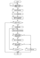
- FIG. 10 is a flowchart illustrating a process procedure in a rescue operation according to an embodiment;
- FIG. 10 is a diagram illustrating an example of a speed of a car of an elevator apparatus according to another embodiment.
- 13 is a flowchart showing a processing procedure in a rescue operation according to another example of the embodiment.
- FIG. 2 is a block diagram showing a configuration of an elevator system including an elevator device which is another example of an embodiment.
- 13 is a flowchart showing a processing procedure in a rescue operation according to another example of the embodiment.
- FIG. 1 is a schematic diagram showing the elevator system 1 according to this embodiment
- Figure 2 is a block diagram showing the configuration of the elevator system 1.
- the elevator system 1 includes an elevator device 10.
- the elevator device 10 is connected to a monitoring center 2 that is provided remotely via a network.
- the monitoring center 2 includes, for example, an operator who monitors the elevator device 10. The operator transmits commands regarding the operation of the elevator device 10 to the elevator device 10 as necessary.
- the elevator device 10 has a car 11, a hoist 12, and a governor 13 that serves as an overspeed detection unit.
- the car 11 is installed in a hoistway 14, which is provided as a space extending vertically within a building.
- the car 11 is provided with a car door 15.
- a platform door 16 provided at the platform opens in conjunction with the car door 15, allowing passengers to board and disembark.
- a machine room 17 is provided above the ceiling of the hoistway 14.
- One end of the main rope 18 is connected to the car 11.
- a counterweight 19 is connected to the other end of the main rope 18.
- the middle portion of the main rope 18 is wound around the drive sheave of the hoist 12, and the main rope 18 moves due to the rotational movement of the drive sheave of the hoist 12. This causes the car 11 and the counterweight 19 to rise and fall in opposite directions.
- the hoist 12 is disposed in the machine room 17 and drives the car 11.
- the hoist 12 is provided with a brake device 20.
- the brake device 20 corresponds to the braking section of the present invention.
- the brake device 20 generates a force to prevent the drive sheave of the hoist 12 from rotating, and applies a braking force to the movement of the car 11.
- the brake device 20 prevents the drive sheave from rotating, for example, by frictional force generated when a brake shoe is pressed against a braking surface that rotates in conjunction with the drive sheave by the force of a spring.
- the brake device 20 operates when the speed governor 13 detects that the speed of the car 11 has reached a reference speed, which will be described in more detail later.
- the brake device 20 may be provided as one of the functions of the hoisting machine 12.
- the governor 13 for example, has a governor rope 21 which is a single circular rope, a governor wheel 22 arranged in the machine room 17, a tension wheel 23, a pendulum (not shown) attached to the governor wheel 22, and an electric switch 24.
- the governor rope 21 is a circular rope arranged vertically within the elevator shaft 14.
- the governor rope 21 has a folded-back portion at the upper end wound around the governor wheel 22, and a folded-back portion at the lower end wound around the tension wheel 23.
- the governor rope 21 is connected and fixed to the car 11 so as to be linked to the ascending and descending movement of the car 11.
- the elevator device 10 further includes an acceleration sensor 25.
- the acceleration sensor 25 is disposed on the upper surface of the car 11.
- the acceleration sensor 25 detects the acceleration of the car 11 in one or more axial directions including at least the vertical direction.
- the acceleration sensor 25 transmits the measured acceleration of the car 11 to the control device 30.
- the control device 30 calculates the speed of the car 11 based on the measured acceleration.
- the acceleration sensor 25 may be an acceleration sensor that measures acceleration in three axial directions. That is, the acceleration sensor 25 may measure acceleration in the X-axis direction, the Y-axis direction, and the Z-axis direction.
- the X-axis direction, the Y-axis direction, and the Z-axis direction are mutually orthogonal.
- the Z-axis direction of the three-axis acceleration sensor is arranged to be the moving direction (up and down direction) of the car 11, the car 11 does not move in the X-axis direction and the Y-axis direction, so that the acceleration in the X-axis direction and the Y-axis direction when the car 11 moves is close to 0.
- the acceleration in the X-axis direction or the Y-axis direction may not be close to 0.
- a three-axis acceleration sensor for the acceleration sensor 25 and measuring the acceleration in the X-axis direction and the Y-axis direction it is possible to detect a malfunction of the acceleration sensor 25 and a deviation such as a tilt from the normal state in the arrangement of the acceleration sensor 25.
- the acceleration sensor 25 may constantly measure the acceleration of the car 11, but preferably measures the acceleration of the car 11 from the point in time when the speed governor 13 detects that the speed of the car 11 has reached the reference speed. This shortens the operating time of the acceleration sensor 25 and reduces the memory capacity of the control device 30. As a result, the price of the control device 30 can be reduced.
- the control device 30 performs overall control of the elevator device 10, including controlling the movement of the car 11.
- the control device 30 has a memory that stores various setting information, control programs, etc., and a processor that realizes the functions of each processing unit by reading and executing the control program.
- the control device 30 is connected to the speed governor 13 and the acceleration sensor 25, and acquires information necessary for control from the speed governor 13 and the acceleration sensor 25.
- the control device 30 is also connected to the hoisting machine 12 and the braking device 20, and is configured to transmit control signals to the hoisting machine 12 and the braking device 20.
- the control device 30 includes an operation control unit 31, a speed measurement unit 32, a malfunction detection unit 33, and a rescue operation unit 34.
- the operation control unit 31 controls the movement of the car 11 by controlling the hoist 12. Note that normal operation means operation other than the rescue operation described below. Furthermore, when the operation control unit 31 detects, based on a signal from the speed governor 13, that the speed of the car 11 has reached the reference speed, it activates the brake device 20 and stops the drive of the hoist 12.
- the malfunction detection unit 33 may determine that the governor 13 has malfunctioned at the time when the control device 30 acquires the overspeed detection signal, or may determine that the governor 13 has malfunctioned after the brake device 20 has been activated and the car 11 has come to a complete halt.
- the rescue operation unit 34 performs rescue operation while measuring the speed of the car 11 with the speed measurement unit 32. Then, if the speed measurement unit 32 detects that the speed of the car 11 has reached an abnormal speed during rescue operation, the rescue operation unit 34 activates the brake device 20 again and stops the drive of the hoist 12. That is, during normal operation, as described above, the speed of the car 11 is monitored by the governor 13, but during rescue operation, the speed of the car 11 is monitored by the speed measurement unit 32, not by the governor 13 in which a malfunction has occurred.
- the abnormal speed is a speed at which it is determined that the car 11 needs to be stopped from the viewpoint of safety, and may be the same as the reference speed or may be different from the reference speed. As a result, even during rescue operation, if it is detected that the speed of the car 11 has reached an abnormal speed, the brake device 20 can be activated, and rescue operation can be performed while ensuring the safety of passengers.
- the communication device 40 transmits information to the monitoring center 2 informing that the speed of the car 11 has reached the reference speed.
- the communication device 40 also transmits the detection result of the malfunction detection unit 33 to the monitoring center 2.
- the communication device 40 may also transmit information regarding the speed of the car 11 measured by the speed measurement unit 32 to the monitoring center 2.
- the communication device 40 may also obtain information from the monitoring center 2 and transmit the information to the control device 30. Examples of information obtained from the monitoring center 2 include a command to start a rescue operation and information regarding the speed and destination of the car 11 during a rescue operation.
- FIG. 3 is a flowchart showing the operation of the elevator system 1, and shows the processing procedure of the control device 30.
- the control device 30 performs rescue operation without receiving a command from the monitoring center 2.
- the control device 30 receives a signal (overspeed detection signal) from the speed governor 13 that detects that the speed of the car 11 has reached the reference speed V1 (step S1: Yes). Then, the control device 30 starts to obtain the acceleration of the car 11 from the acceleration sensor 25 from the time when the overspeed detection signal is received (step S2). Immediately after that, the control device 30 activates the brake device 20 and stops the drive of the hoist 12 (step S3). The control device 30 obtains the acceleration of the car 11 from the acceleration sensor 25 until the drive of the hoist 12 stops and the movement of the car 11 completely stops. Note that when the control device 30 activates the brake device 20, it may inform passengers that the car 11 will stop through a monitor, speaker, etc. provided inside the car 11.
- step S4 uses the acquired acceleration data of the car 11 to calculate the speed of the car 11 at the time of acquiring the overspeed detection signal (step S4).
- step S5 the control device 30 compares the calculated speed with a predetermined reference speed V1 to determine whether the speed governor 13 has malfunctioned. If the calculated speed is smaller than the reference speed V1, the control device 30 determines that the speed governor 13 has malfunctioned (step S5: Yes). On the other hand, if the calculated speed is equal to or greater than the reference speed V1, that is, if the speed governor 13 has not malfunctioned (step S5: No), an overspeed has actually occurred, and therefore some abnormality may have occurred in the elevator device 10. Therefore, since it is difficult to perform rescue operations from step S6 to step S11 described below while ensuring the safety of passengers, this flow is terminated.
- step S6 the control device 30 performs rescue operation. More specifically, the control device 30 shorts and disables the circuit of the safety device, including the electric switch 24, and then releases the brake device 20. Then, the control device 30 controls the drive of the hoist 12 to move the car 11 to the landing position of the nearest floor.
- rescue operation passengers may be notified that rescue operation is about to begin through a monitor, speaker, etc. provided inside the car 11.
- the control device 30 acquires the acceleration of the car 11 from the acceleration sensor 25 (step S7). Then, based on the acquired acceleration of the car 11, it calculates the speed of the car 11 during rescue operation (step S8).
- step S9 the calculated speed is compared with a predetermined abnormal speed V2. If the calculated speed is less than the abnormal speed V2 (step S9: Yes), rescue operation is being performed normally and rescue operation is continued. On the other hand, if the calculated speed is equal to or greater than the abnormal speed V2, overspeeding is occurring during rescue operation. Therefore, the control device 30 activates the brake device 20 (step S10) and stops rescue operation.
- step S11 determines in step S11 whether the rescue operation is completed, i.e., whether the car 11 has moved to the landing position of the nearest floor. If the rescue operation is not completed (step S11: No), the process returns to step S7 and the rescue operation is continued while monitoring the speed of the car 11. On the other hand, if the rescue operation is completed (step S11: Yes), this flow is terminated.
- FIG. 4 is a diagram showing an example of an actual change in speed of the car 11 when the governor 13 detects that the car 11 is overspeeding and the brake device 20 is activated.
- FIG. 5 is a flowchart showing the operation of the elevator system 1 of this embodiment, showing the processing procedure of the control device 30. As will be described in detail later, in this embodiment, the method of calculating the speed of the car 11 by the speed measurement unit 32 differs from the first embodiment.
- FIG. 5 shows the processing procedure of the control device 30 that takes into account the correction of the zero point of the acceleration sensor 25. As with the flow shown in FIG. 3, this illustrates an example in which the control device 30 performs rescue operation without receiving a command from the monitoring center 2.
- the control device 30 acquires a signal (overspeed detection signal) from the speed governor 13 that detects that the speed of the car 11 has reached the reference speed V1 (step S21: Yes). The control device 30 then starts acquiring the acceleration of the car 11 from the acceleration sensor 25 from the point in time when the overspeed detection signal is acquired (step S22). Immediately thereafter, the control device 30 activates the brake device 20 and stops the drive of the hoist 12 (step S23). The control device 30 acquires the acceleration of the car 11 from the acceleration sensor 25 until the drive of the hoist 12 stops and the movement of the car 11 comes to a complete halt.
- a signal overspeed detection signal
- step S25 it is determined whether the acquired offset value is within a predetermined range. If the acquired offset value is not within the predetermined range (step S25: No), that is, if a certain amount of acceleration is detected even though the car 11 is stopped, there is a possibility that an abnormality has occurred in the acceleration sensor 25. As a result, it is difficult to perform rescue operation while ensuring the safety of passengers, so this flow is terminated. Note that if there is a possibility that an abnormality has occurred in the acceleration sensor 25, the control device 30 may transmit information informing the monitoring center 2 of the abnormality.
- step S25 if the acquired offset value is within a predetermined range (step S25: Yes), an offset correction is performed on the acceleration data of the car 11 at the time when the overspeed detection signal was acquired based on the offset value. Then, based on the acceleration data after the offset correction, the speed of the car 11 at the time when the overspeed detection signal was acquired is calculated (step S26).
- the control device 30 compares the calculated speed with a predetermined reference speed V1 to determine whether the governor 13 has malfunctioned (step S27). If the calculated speed is smaller than the reference speed V1, the control device 30 determines that the governor 13 has malfunctioned (step S27: Yes). On the other hand, if the calculated speed is equal to or greater than the reference speed V1 (step S27: No), i.e., if the governor 13 has not malfunctioned, an overspeed has actually occurred, and this flow is terminated.
- step S28 if there is a malfunction of the speed governor 13, the control device 30 performs rescue operation (step S28).
- the car 11 may be operated at a speed lower than that during normal operation so that it can be stopped immediately if any abnormality occurs.
- the control device 30 acquires the acceleration of the car 11 from the acceleration sensor 25 (step S29). Then, based on the acquired acceleration of the car 11, the control device 30 calculates the speed of the car 11 during rescue operation (step S30). At this time, it is preferable to calculate the speed of the car 11 after performing an offset correction based on the offset value acquired in step S24. This makes it possible to accurately calculate the speed of the car 11. As a result, rescue operation can be performed while further ensuring the safety of passengers.
- step S31 the calculated speed is compared with an abnormal speed V2 that corresponds to a predetermined speed of the car 11 during rescue operation. If the calculated speed is less than the abnormal speed V2 (step S31: Yes), rescue operation is being performed normally and rescue operation is continued. On the other hand, if the calculated speed is equal to or greater than the abnormal speed V2, overspeeding is occurring during rescue operation. Therefore, the control device 30 activates the brake device 20 (step S32) and stops rescue operation.
- step S33 determines in step S33 whether the rescue operation is completed, i.e., whether the car 11 has moved to the landing position of the nearest floor. If the rescue operation is not completed (step S33: No), the process returns to step S29 and the rescue operation is continued while monitoring the speed of the car 11. On the other hand, if the rescue operation is completed (step S33: Yes), this flow is terminated.
- FIG. 6 is a block diagram showing the configuration of the elevator system 1 of this embodiment.
- FIG. 7 is a flowchart showing the operation of the elevator system 1 of this embodiment, showing the processing procedure of the control device 30.
- the acceleration sensor 25 is an acceleration sensor that measures acceleration in three axial directions.
- the control device 30 includes an abnormality detection unit 35 in addition to an operation control unit 31, a speed measurement unit 32, a malfunction detection unit 33, and a rescue operation unit 34.
- the abnormality detection unit 35 detects an abnormality in the acceleration sensor 25 based on the values measured by the acceleration sensor 25. More specifically, the abnormality detection unit 35 detects an abnormality in the acceleration sensor 25 when, among the accelerations in the three axial directions measured by the acceleration sensor 25, the acceleration in a direction perpendicular to the moving direction (up and down direction) of the car 11 is greater than a predetermined specified value. For example, when the Z-axis direction of the three-axis acceleration sensor is arranged so that it is the up and down direction, the accelerations in the X-axis and Y-axis directions when the car 11 is moving should be values close to 0. Therefore, the abnormality detection unit 35 determines that an abnormality has occurred in the acceleration sensor 25 when the accelerations in the X-axis and Y-axis directions are equal to or greater than a predetermined specified value.
- FIG. 7 shows the processing procedure of the control device 30 taking into consideration the detection of an abnormality in the acceleration sensor 25.
- this illustrates an example in which the control device 30 performs rescue operation without receiving a command from the monitoring center 2.
- the Z-axis direction of the three-axis acceleration sensor is arranged to coincide with the direction of movement of the car 11.
- the brake device 20 is activated to stop rescue operation (step S51). Note that if there is a possibility that an abnormality has occurred in the acceleration sensor 25, the control device 30 may transmit information notifying the abnormality to the monitoring center 2.
- step S49 the control device 30 calculates the speed of the car 11 during rescue operation based on the acceleration obtained from the acceleration sensor 25.
- the control device 30 may calculate the speed of the car 11 using only the acceleration in the Z-axis direction, or may calculate the speed of the car 11 by calculating a composite acceleration from the accelerations in the X-axis, Y-axis, and Z-axis directions and integrating the composite acceleration over time. In this case, even if the Z-axis direction and the up-down direction of the acceleration sensor 25 do not strictly match, the speed of the car 11 can be accurately calculated. Note that the subsequent flow is similar to the flow of the first embodiment shown in Figure 3.
- a rail may be provided on the side of the elevator 14, and a roller that moves in synchronization with the car 11 may be pressed against the rail to rotate, the rotational position may be detected by an encoder-type rotational position sensor, and the speed of the car 11 may be calculated from the output of the rotational position sensor.
- a speed sensor may be provided to measure the speed of the car 11 from the output of each of the position sensors, and the measurement value of the speed sensor may be output to the control device 30.
- the speed measurement unit 32 that measures the speed of the car 11 when the overspeed detection unit detects that the speed of the car 11 has reached the reference speed may be composed of the speed sensor and a speed acquisition unit that is provided in the control device 30 and acquires the measurement value of the speed sensor.
- the control device 30 may activate the brake device 20 and stop the rescue operation. If the variation in the measurement values of the multiple acceleration sensors 25 is equal to or greater than a predetermined value, there is a possibility that an abnormality has occurred in the acceleration sensor 25. Therefore, by stopping the rescue operation in the above case, the safety of passengers can be further ensured. Similarly, if multiple position sensors or speed sensors are provided as described above, and the variation in the measurement values of the multiple position sensors or speed sensors is equal to or greater than a predetermined value, the control device 30 may activate the brake device 20 and stop the rescue operation.
- the electric switch 24 provided in the speed governor 13 detects that the speed of the car 11 has reached the reference speed, but this is not limited to this.
- an optical or magnetic rotational position sensor may be provided in the speed governor 13 to detect the rotational angle of the speed governor 13, and based on the change in the rotational angle over time, it may be detected that the speed of the car 11 has reached the reference speed.
- the electric switch 24 may be used in combination with the rotational position sensor provided in the speed governor 13 as a configuration for detecting that the speed of the car 11 has reached the reference speed.
- a camera, sensor, etc. that detects the presence or absence of passengers may be provided inside the car 11, and rescue operation may be performed only when there is a passenger inside the car 11. In other words, if there is no passenger inside the car 11, a malfunction of the governor 13 may not be detected, and rescue operation may not be performed.
- Elevator system 2. Monitoring center, 10. Elevator equipment, 11. Car, 12. Hoisting machine, 13. Governor, 14. Hoistway, 15. Car door, 16. Landing door, 17. Machine room, 18. Main rope, 19. Counterweight, 20. Brake equipment, 21. Governor rope, 22. Governor car, 23. Tensioner, 24. Electric switch, 25. Acceleration sensor, 30. Control device, 31. Operation control unit, 32. Speed measurement unit, 33. Malfunction detection unit, 34. Rescue operation unit, 35. Abnormality detection unit, 40. Communication device
Landscapes
- Maintenance And Inspection Apparatuses For Elevators (AREA)
Priority Applications (2)
| Application Number | Priority Date | Filing Date | Title |
|---|---|---|---|
| PCT/JP2023/038273 WO2025088681A1 (ja) | 2023-10-24 | 2023-10-24 | エレベーター装置 |
| JP2024541861A JP7580677B1 (ja) | 2023-10-24 | 2023-10-24 | エレベーター装置 |
Applications Claiming Priority (1)
| Application Number | Priority Date | Filing Date | Title |
|---|---|---|---|
| PCT/JP2023/038273 WO2025088681A1 (ja) | 2023-10-24 | 2023-10-24 | エレベーター装置 |
Publications (1)
| Publication Number | Publication Date |
|---|---|
| WO2025088681A1 true WO2025088681A1 (ja) | 2025-05-01 |
Family
ID=93429276
Family Applications (1)
| Application Number | Title | Priority Date | Filing Date |
|---|---|---|---|
| PCT/JP2023/038273 Pending WO2025088681A1 (ja) | 2023-10-24 | 2023-10-24 | エレベーター装置 |
Country Status (2)
| Country | Link |
|---|---|
| JP (1) | JP7580677B1 (https=) |
| WO (1) | WO2025088681A1 (https=) |
Families Citing this family (1)
| Publication number | Priority date | Publication date | Assignee | Title |
|---|---|---|---|---|
| JP7794356B1 (ja) * | 2025-06-19 | 2026-01-06 | 三菱電機ビルソリューションズ株式会社 | エレベータの異常検出装置およびエレベータの異常検出方法 |
Citations (6)
| Publication number | Priority date | Publication date | Assignee | Title |
|---|---|---|---|---|
| JPS5742470A (en) * | 1980-08-28 | 1982-03-10 | Mitsubishi Electric Corp | Safety device for elevator |
| US20130240301A1 (en) * | 2010-11-18 | 2013-09-19 | Kone Corporation | Backup circuit for electricity supply, elevator system, and method |
| WO2014097373A1 (ja) * | 2012-12-17 | 2014-06-26 | 三菱電機株式会社 | エレベータ装置 |
| CN208500054U (zh) * | 2018-06-29 | 2019-02-15 | 苏州江南嘉捷电梯有限公司 | 一种带自监测装置的电梯限速器系统 |
| JP2019210086A (ja) * | 2018-06-01 | 2019-12-12 | 株式会社日立ビルシステム | エレベーター異常監視システム及びエレベーター異常監視方法 |
| WO2022185511A1 (ja) * | 2021-03-05 | 2022-09-09 | 三菱電機ビルテクノサービス株式会社 | エレベーター装置 |
Family Cites Families (1)
| Publication number | Priority date | Publication date | Assignee | Title |
|---|---|---|---|---|
| JP6567922B2 (ja) * | 2015-08-19 | 2019-08-28 | 株式会社日立製作所 | エレベータ |
-
2023
- 2023-10-24 JP JP2024541861A patent/JP7580677B1/ja active Active
- 2023-10-24 WO PCT/JP2023/038273 patent/WO2025088681A1/ja active Pending
Patent Citations (6)
| Publication number | Priority date | Publication date | Assignee | Title |
|---|---|---|---|---|
| JPS5742470A (en) * | 1980-08-28 | 1982-03-10 | Mitsubishi Electric Corp | Safety device for elevator |
| US20130240301A1 (en) * | 2010-11-18 | 2013-09-19 | Kone Corporation | Backup circuit for electricity supply, elevator system, and method |
| WO2014097373A1 (ja) * | 2012-12-17 | 2014-06-26 | 三菱電機株式会社 | エレベータ装置 |
| JP2019210086A (ja) * | 2018-06-01 | 2019-12-12 | 株式会社日立ビルシステム | エレベーター異常監視システム及びエレベーター異常監視方法 |
| CN208500054U (zh) * | 2018-06-29 | 2019-02-15 | 苏州江南嘉捷电梯有限公司 | 一种带自监测装置的电梯限速器系统 |
| WO2022185511A1 (ja) * | 2021-03-05 | 2022-09-09 | 三菱電機ビルテクノサービス株式会社 | エレベーター装置 |
Also Published As
| Publication number | Publication date |
|---|---|
| JP7580677B1 (ja) | 2024-11-11 |
| JPWO2025088681A1 (https=) | 2025-05-01 |
Similar Documents
| Publication | Publication Date | Title |
|---|---|---|
| JP4368854B2 (ja) | エレベータ装置 | |
| RU2369554C2 (ru) | Контроль состояния лифта | |
| EP3421400B1 (en) | Health monitoring systems and methods for elevator systems | |
| JP4855416B2 (ja) | エレベータの制御装置 | |
| CN104718148A (zh) | 电梯设备的安全装置 | |
| JP2012520809A (ja) | エレベータ用過加速度・過速度防止システム | |
| EP3459890B1 (en) | Health monitoring of safety braking systems for elevators | |
| WO2010084581A1 (ja) | エレベータ装置 | |
| US20150251877A1 (en) | Elevator apparatus | |
| WO2010067435A1 (ja) | エレベータ装置 | |
| EP3960673B1 (en) | Elevator systems | |
| JP7580677B1 (ja) | エレベーター装置 | |
| EP3381853B1 (en) | Elevator overtravel testing systems and methods | |
| JP5523455B2 (ja) | エレベータ装置 | |
| EP4177206B1 (en) | Avoiding entrapment in an elevator system | |
| JP2013049568A (ja) | 巻上機のブレーキ保持トルク調整装置及びそのブレーキ保持トルク調整方法 | |
| JP7140634B2 (ja) | エレベーターの制御システム | |
| JP6545868B1 (ja) | エレベータシステム | |
| JPH08165070A (ja) | エレベータの制動性監視装置 | |
| WO2007077828A1 (ja) | エレベータ | |
| JP7769107B2 (ja) | エレベータ用ガバナシステムの検査装置および検査方法 | |
| US20250026609A1 (en) | Elevator system and a method | |
| EP4474330B1 (en) | Elevator and method for demonstrating operation of elevator safety system | |
| JP7315119B2 (ja) | エレベーターの監視装置 | |
| EP4431429A1 (en) | Elevator safety system, elevator system and elevator car rescue run method |
Legal Events
| Date | Code | Title | Description |
|---|---|---|---|
| ENP | Entry into the national phase |
Ref document number: 2024541861 Country of ref document: JP Kind code of ref document: A |
|
| WWE | Wipo information: entry into national phase |
Ref document number: 2024541861 Country of ref document: JP |
|
| 121 | Ep: the epo has been informed by wipo that ep was designated in this application |
Ref document number: 23956739 Country of ref document: EP Kind code of ref document: A1 |