WO2025074641A1 - 昇降路内機器配置支援システム - Google Patents
昇降路内機器配置支援システム Download PDFInfo
- Publication number
- WO2025074641A1 WO2025074641A1 PCT/JP2023/036635 JP2023036635W WO2025074641A1 WO 2025074641 A1 WO2025074641 A1 WO 2025074641A1 JP 2023036635 W JP2023036635 W JP 2023036635W WO 2025074641 A1 WO2025074641 A1 WO 2025074641A1
- Authority
- WO
- WIPO (PCT)
- Prior art keywords
- unit
- elevator shaft
- data
- dimensional model
- model data
- Prior art date
- Legal status (The legal status is an assumption and is not a legal conclusion. Google has not performed a legal analysis and makes no representation as to the accuracy of the status listed.)
- Pending
Links
Images















Classifications
-
- B—PERFORMING OPERATIONS; TRANSPORTING
- B66—HOISTING; LIFTING; HAULING
- B66B—ELEVATORS; ESCALATORS OR MOVING WALKWAYS
- B66B3/00—Applications of devices for indicating or signalling operating conditions of elevators
Definitions
- This disclosure relates to an elevator shaft equipment placement support system.
- An elevator exterior display system includes a display unit that displays a three-dimensional model of the elevator, and the display unit detects changes in the user's field of vision and displays an image of the three-dimensional model projected into the field of vision (see, for example, Patent Document 1).
- the present disclosure has been made to solve these problems. Its purpose is to provide an elevator shaft equipment layout support system that enables on-site workers to easily check the layout of equipment, etc. to be installed in an elevator shaft that has been designed in advance, and that can easily modify 3D model data of equipment, etc. according to the actual conditions in the elevator shaft, thereby supporting the work of arranging equipment in the elevator shaft.
- the elevator shaft equipment placement support system includes an image acquisition unit that acquires an image of the inside of an elevator shaft in real space, a data acquisition unit that acquires coordinate data of the inside of the elevator shaft and three-dimensional model data of objects to be installed in the elevator shaft from a data management unit that stores the coordinate data and the three-dimensional model data of the objects to be installed in the elevator shaft, a display unit that displays an augmented reality image generated by superimposing the three-dimensional model data of the objects acquired from the data management unit on the image of the inside of the elevator shaft in the real space, an operation detection unit that detects a selection operation for individually selecting the objects and a movement operation for the selected objects in the augmented reality image, an update unit that updates the three-dimensional model data of the objects to reflect changes in the orientation and position of the objects due to the movement operation, and a transmission unit that transmits the updated three-dimensional model data of the objects to the data management unit.
- the elevator shaft equipment placement support system disclosed herein allows on-site workers to easily check the placement of equipment, etc. to be installed in the elevator shaft that has been designed in advance, and also allows for easy correction of 3D model data of equipment, etc. according to the actual conditions in the elevator shaft, thereby supporting the work of placing equipment in the elevator shaft.
- FIG. 1 is a block diagram showing an overall configuration of a hoistway equipment layout support system according to a first embodiment
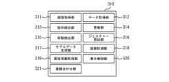
- FIG. 2 is a block diagram showing the configuration of a processing unit of the AR glasses of the elevator shaft equipment layout support system according to the first embodiment
- FIG. 13 is a block diagram showing a configuration of a terminal processing unit in a modified example of the hoistway equipment layout assistance system according to the first embodiment.
- FIG. 11 is a flow diagram showing an example of a process for identifying a beacon terminal position in the elevator shaft equipment arrangement support system according to the first embodiment.
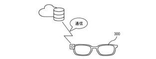
- FIG. 11 is a diagram showing the start of communication of the AR glasses of the elevator shaft equipment layout assistance system according to the first embodiment.
- FIG. 11 is a diagram showing an example of a main operation screen displayed on the AR glasses of the elevator shaft equipment layout support system according to the first embodiment.
- FIG. 13 is a diagram showing an example of a beacon terminal setting screen displayed on the AR glasses of the elevator shaft equipment layout support system according to the first embodiment;
- FIG. 13 is a diagram showing an example of a beacon terminal selection screen displayed on the AR glasses of the elevator shaft equipment arrangement support system according to the first embodiment.
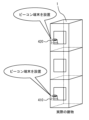
- 1 is a perspective view showing an example of installation of a beacon terminal in a shaft equipment layout support system according to embodiment 1.
- FIG. FIG. 11 is a diagram showing an example of a three-dimensional coordinate data display screen displayed on the AR glasses of the elevator shaft equipment layout assistance system according to the first embodiment.
- FIG. 10 is a diagram illustrating the designation of the position of a beacon terminal in three-dimensional coordinate data within a hoistway in the hoistway equipment layout assistance system according to the first embodiment.
- FIG. FIG. 4 is a flow diagram showing an example of a coordinate alignment process of the elevator shaft equipment layout support system according to the first embodiment.
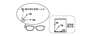
- FIG. 2 is a diagram for explaining coordinate alignment in the hoistway equipment layout assistance system according to the first embodiment.
- FIG. 2 is a diagram for explaining coordinate alignment in the hoistway equipment layout assistance system according to the first embodiment.
- FIG. 2 is a diagram for explaining coordinate alignment in the hoistway equipment layout assistance system according to the first embodiment.
- FIG. 11 is a flow diagram showing an example of an augmented reality image display process of the elevator shaft equipment arrangement support system according to the first embodiment.
- FIG. 13 is a diagram showing an example of a three-dimensional data display selection screen displayed on the AR glasses of the elevator shaft equipment layout support system according to the first embodiment.
- 1 is a diagram showing an example of an augmented reality image when looking at a front wall inside a hoistway in the hoistway in-hoistway equipment layout assistance system according to embodiment 1.
- FIG. 2 is a diagram showing an example of an augmented reality image when looking at the hall side from inside the hoistway in the hoistway equipment layout assistance system according to the first embodiment.
- FIG. 11 is a flow diagram showing an example of a process for moving an object within an augmented reality image of the elevator shaft equipment layout assistance system according to the first embodiment.
- FIG. 2 is a perspective view illustrating an example of equipment interference in the elevator shaft equipment layout assistance system according to the first embodiment.
- FIG. 13 is a diagram showing an example of a screen displayed on the AR glasses of the elevator shaft equipment layout support system according to the first embodiment when selecting a three-dimensional data operation.
- FIG. 2 is a diagram showing an example of a screen display during an object selection operation in the elevator shaft equipment layout assistance system according to the first embodiment.
- FIG. 13 is a diagram showing an example of a screen display after an object is moved in the elevator shaft equipment layout assistance system according to the first embodiment.
- FIG. 11 is a flow diagram showing an example of an object addition process for adding an obstacle or the like that caused a change in layout of the elevator shaft equipment layout assistance system according to the first embodiment.
- FIG. 11 is a diagram showing an example of a screen when inputting object attribute information in the hoistway equipment layout assistance system according to the first embodiment.
- FIG. 13 is a diagram showing an example of a screen display when an object is added in the elevator shaft equipment layout assistance system according to the first embodiment.
- 1 is a diagram showing an example of display of inter-object distances in the elevator shaft equipment layout assistance system according to the first embodiment;
- FIG. 10A to 10C are diagrams illustrating an example of object generation in the hoistway equipment layout assistance system according to the first embodiment.
- FIG. 11 is a flow diagram showing an example of a process for confirming changes in the hoistway equipment layout support system according to the first embodiment.
- 10 is a diagram for explaining a confirmation operation of data change contents in the elevator shaft equipment layout support system according to the first embodiment.
- FIG. FIG. 11 is a flow diagram showing an example of an equipment layout process at another work site of the elevator shaft equipment layout support system according to the first embodiment.
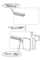
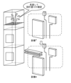
- 11 is a diagram showing an example of a case where a beacon terminal of the elevator shaft equipment arrangement support system according to the first embodiment is moved to another work location.
- FIG. 13 is a diagram showing an example of a case where a beacon terminal of the elevator shaft equipment arrangement support system according to the first embodiment is additionally installed at another work location.
- FIG. FIG. 4 is a flow diagram showing an example of a process for revising three-dimensional model data of the elevator shaft equipment layout support system according to the first embodiment.
- 11 is a diagram showing an example of a case where three-dimensional model data is revised on a PC in the elevator shaft equipment layout assistance system according to the first embodiment.
- FIG. 13 is a diagram showing an example of a case where three-dimensional model data is revised using AR glasses in the elevator shaft equipment layout assistance system according to the first embodiment.
- FIG. FIG. 2 is a block diagram showing an overall configuration of a first modified example of the hoistway equipment layout assistance system according to the first embodiment.
- FIG. 13 is a block diagram showing an overall configuration of a second modified example of the hoistway equipment layout assistance system according to the first embodiment.
- FIG. 13 is a block diagram showing the configuration of a processing unit of VR glasses in a second modified example of the elevator shaft equipment layout assistance system according to embodiment 1.
- FIG. 13 is a flow diagram showing an example of equipment layout processing in a second modified example of the shaft equipment layout assistance system according to embodiment 1.
- FIG. 13 is a diagram showing an example of a case where three-dimensional model data is revised using VR glasses in a second modified example of the elevator shaft equipment layout assistance system according to embodiment 1.
- FIG. 1 is a block diagram showing an overall configuration of an in-hoistway equipment layout support system.
- Fig. 2 is a block diagram showing a configuration of a processing unit of an AR glass in the in-hoistway equipment layout support system.
- Fig. 3 is a block diagram showing a configuration of a terminal processing unit in a modified example of the in-hoistway equipment layout support system.
- FIG. 4 is a flow diagram showing an example of a process for identifying the position of a beacon terminal in the elevator shaft equipment layout support system.
- FIG. 5 is a diagram showing the start of communication of the AR glasses of the elevator shaft equipment layout support system.
- FIG. 6 is a diagram showing an example of a main operation screen displayed on the AR glasses of the elevator shaft equipment layout support system.
- FIG. 7 is a diagram showing an example of a beacon terminal setting screen displayed on the AR glasses of the elevator shaft equipment layout support system.
- FIG. 8 is a diagram showing an example of a beacon terminal selection screen displayed on the AR glasses of the elevator shaft equipment layout support system.
- FIG. 9 is a perspective view showing an example of the installation of a beacon terminal in the elevator shaft equipment layout support system.
- FIG. 5 is a diagram showing the start of communication of the AR glasses of the elevator shaft equipment layout support system.
- FIG. 6 is a diagram showing an example of a main operation screen displayed on the AR glasses of the elevator shaft equipment layout support system.
- FIG. 7 is
- FIG. 10 is a diagram showing an example of a three-dimensional coordinate data display screen displayed on the AR glasses of the elevator shaft equipment layout support system.
- FIG. 11 is a diagram explaining the designation of the position of a beacon terminal in three-dimensional coordinate data in the elevator shaft in the elevator shaft equipment layout support system.
- FIG. 12 is a flow diagram showing an example of the coordinate alignment process of the elevator shaft equipment layout support system.
- FIG. 13 to FIG. 15 is a diagram explaining the coordinate alignment in the elevator shaft equipment layout support system.
- Figure 16 is a flow diagram showing an example of an augmented reality image display process in the elevator shaft equipment layout support system.
- Figure 17 is a diagram showing an example of a 3D data display selection screen displayed on the AR glasses of the elevator shaft equipment layout support system.
- Figure 18 is a diagram showing an example of an augmented reality image when looking at the front wall inside the elevator shaft in the elevator shaft equipment layout support system.
- Figure 19 is a diagram showing an example of an augmented reality image when looking at the landing side from inside the elevator shaft in the elevator shaft equipment layout support system.
- Figure 20 is a flow diagram showing an example of object movement processing within an augmented reality image of the elevator shaft equipment layout support system.
- Figure 21 is a perspective view explaining an example of equipment interference in the elevator shaft equipment layout support system.
- Figure 22 is a diagram showing an example of a screen displayed on the AR glasses of the elevator shaft equipment layout support system when selecting a 3D data operation.
- Figure 23 is a diagram showing an example of a screen display during an object selection operation in the elevator shaft equipment layout support system.
- Figure 24 is a diagram showing an example of a screen display after an object has been moved in the elevator shaft equipment layout support system.
- Figure 25 is a flow diagram showing an example of an object addition process for an obstacle or the like that has caused a change in layout in the elevator shaft equipment layout support system.
- Figure 26 is a diagram showing an example of a screen when object attribute information is input in the elevator shaft equipment layout support system.
- Figure 27 is a diagram showing an example of a screen display when an object is added in the elevator shaft equipment layout support system.
- Figure 28 is a diagram showing an example of a display of the distance between objects in the elevator shaft equipment layout support system.
- Figure 29 is a diagram explaining an example of object generation in the elevator shaft equipment layout support system.
- Figure 30 is a flow diagram showing an example of a process for confirming changes to the elevator shaft equipment layout support system.
- Figure 31 is a diagram explaining the process for confirming data changes to the elevator shaft equipment layout support system.
- FIG. 32 is a flow diagram showing an example of equipment placement processing at another work location in the elevator shaft equipment placement support system.
- FIG. 33 is a diagram showing an example of moving a beacon terminal of the elevator shaft equipment placement support system to another work location.
- FIG. 34 is a diagram showing an example of additionally installing a beacon terminal of the elevator shaft equipment placement support system to another work location.
- Figure 35 is a flow diagram showing an example of a process for revising three-dimensional model data in the elevator shaft equipment layout support system.
- Figure 36 is a diagram showing an example of revising three-dimensional model data using a PC in the elevator shaft equipment layout support system.
- Figure 37 is a diagram showing an example of revising three-dimensional model data using AR glasses in the elevator shaft equipment layout support system.
- Figure 38 is a block diagram showing the overall configuration of a first variant of the elevator shaft equipment layout support system.
- Figure 39 is a block diagram showing the overall configuration of a second variant of the elevator shaft equipment layout support system.
- Figure 40 is a block diagram showing the configuration of the processing unit of the VR glasses in the second variant of the elevator shaft equipment layout support system.
- Figure 41 is a flow diagram showing an example of equipment layout processing in the second variant of the elevator shaft equipment layout support system.
- Figure 42 is a diagram showing an example of revising three-dimensional model data using VR glasses in the second variant of the elevator shaft equipment layout support system.
- Figure 43 is a diagram showing an example of a configuration that realizes the functions of the terminal processing unit, glass processing unit, positioning device processing unit, and VR glass processing unit of the elevator shaft equipment layout support system.
- one configuration example of the elevator shaft equipment layout support system includes a terminal device 100, a cloud server 200, and AR glasses 300.
- the terminal device 100 is an information processing device such as a PC, a smartphone, or a tablet terminal.
- the terminal device 100 includes a terminal communication unit 101, a terminal processing unit 110, and a human interface unit 103.
- the device processing unit 110 has the function of performing calculations on data and the like to execute predetermined processing.
- the device communication unit 101 is a communication interface that enables the terminal device 100 to communicate with the cloud server 200.
- the device communication unit 101 may be configured as a physically structured circuit, in which case the device communication unit 101 may be referred to as a communication circuit.
- the device communication unit 101 is capable of transmitting data received from the device processing unit 110 to the cloud server 200.
- the device communication unit 101 can also receive data transmitted from the cloud server 200 and pass the received data to the device processing unit 110.
- the human interface unit 103 is an interface between the terminal device 100 and the user.
- the human interface unit 103 includes, for example, a display unit and an operation unit.
- the display unit is a liquid crystal display, an LED display, an organic EL display, etc., capable of displaying various information to the user.
- the operation unit is a keyboard, a mouse, etc., for the user to input various information.
- the human interface unit 103 may also include a touch panel, a non-contact panel, etc., that serves as both the display unit and the operation unit.
- the cloud server 200 is a server device realized by a collection of multiple information processing devices.
- the cloud server 200 includes a server communication unit 201 and a data management unit 202.
- the server communication unit 201 and the data management unit 202 may be provided in a server device consisting of a single information processing device, rather than a collection of multiple information processing devices.
- the server communication unit 201 is a communication interface through which the cloud server 200 communicates with each of the terminal device 100 and the AR glasses 300.
- the server communication unit 201 may be configured as a physically structured circuit, in which case the server communication unit 201 may be referred to as a communication circuit.
- the server communication unit 201 is capable of transmitting data received from the data management unit 202 to one or both of the terminal device 100 and the AR glasses 300.
- the server communication unit 201 is also capable of receiving data transmitted from the terminal device 100 or the AR glasses 300, and passing the received data to the data management unit 202.
- the data management unit 202 manages various data handled by the elevator shaft equipment layout support system.
- the data managed by the data management unit 202 includes coordinate data in the elevator shaft 1 and three-dimensional model data of objects installed in the elevator shaft 1.
- the data management unit 202 stores the coordinate data in the elevator shaft 1 and the three-dimensional model data of objects.
- the coordinate data in the elevator shaft 1 is data for expressing the position in the elevator shaft 1 on a three-dimensional coordinate system having, for example, an X-axis, a Y-axis, and a Z-axis.
- the objects installed in the elevator shaft 1 include, for example, various devices installed in the elevator shaft 1, such as a control panel, a junction box, a weighing device, a speed governor, a hoist, etc., and wiring connecting these devices, etc.
- the three-dimensional model data of the objects installed in the elevator shaft 1 is data that represents the shape and size of the three-dimensional models of these devices, wiring, etc., as well as the position and orientation in the elevator shaft 1 on the above-mentioned three-dimensional coordinate system.
- the data managed by the data management unit 202 may also include images captured by field workers using a camera.
- the AR glasses 300 are glasses-type or helmet-type devices that are worn on the user's face or head. AR is an abbreviation for "Augmented Reality.”
- the AR glasses 300 include a glass communication unit 301, a display unit 302, an operation unit 303, a camera 304, a sensor 305, a glass memory unit 306, and a glass processing unit 310.
- the glass communication unit 301 is a communication interface for the AR glass 300 to communicate with the cloud server 200.
- the glass communication unit 301 may be configured as a physically structured circuit, in which case the glass communication unit 301 may be referred to as a communication circuit.
- the glass communication unit 301 is capable of transmitting data received from the glass processing unit 310 to the cloud server 200.
- the glass communication unit 301 can also receive data transmitted from the cloud server 200 and pass the received data to the glass processing unit 310.
- Camera 304 captures images of real space.
- the images include not only photographs but also images or videos in which part or the entire elevator shaft is mapped.
- camera 304 is positioned facing forward of AR glasses 300 and can capture images in the same direction as the face of a user wearing the AR glasses 300. This allows camera 304 to capture images of real space in the same range as the field of vision of a user wearing the AR glasses 300, depending on the face direction of the user.
- the display unit 302 and the operation unit 303 are interfaces between the AR glasses 300 and a user wearing the AR glasses 300.
- the display unit 302 is a liquid crystal device, an LED device, an organic EL device, etc., capable of displaying various information to the user.
- the display unit 302 is visualized in front of the eyes of the user wearing the AR glasses 300.
- the operation unit 303 is, for example, a remote controller, a button, a switch, a stick, a touch pad, etc., which allows the user to operate the AR glasses 300 and input various information. Note that one or both of an operation detection unit 313 and a gesture detection unit 316, which will be described later, may be used together with or instead of the operation unit 303.
- the sensor 305 is for detecting the behavior of the AR glasses 300 in accordance with the behavior of a user wearing the AR glasses 300.
- the sensor 305 is, for example, a 6DoF (Six-Degrees of Freedom) sensor.
- the sensor 305 which is a 6DoF sensor, can detect acceleration in each of the X-axis, Y-axis, and Z-axis directions, and rotational angular acceleration around each of the X-axis, Y-axis, and Z-axis.
- Such a sensor 305 can detect changes in the position and orientation of the AR glasses 300 in three-dimensional space.
- the glass memory unit 306 stores various data related to the operation control of the AR glasses 300.
- the glass memory unit 306 stores coordinate data within the elevator shaft 1 and three-dimensional model data of objects transmitted from the cloud server 200.
- the glass memory unit 306 also stores images captured by the camera 304.
- the glass processing unit 310 has the function of performing calculations and the like using mainly the data stored in the glass memory unit 306, and executing predetermined processing required for the operation control of the AR glasses 300.
- the communication between the terminal device 100 and the cloud server 200 may be wired or wireless.
- the communication between the AR glasses 300 and the cloud server 200 be wireless.
- One or both of the communication between the terminal device 100 and the cloud server 200 and the communication between the AR glasses 300 and the cloud server 200 may be performed via a communication network such as the Internet.
- a communication network there are usually multiple communication nodes on the communication path.
- the communication between the AR glasses 300 and the communication node closest to the AR glasses 300 be wireless.
- the elevator shaft equipment layout support system may or may not include the terminal device 100.
- the terminal processing unit 110 of the terminal device 100 may be provided with some or all of the functions described below that are provided in the glass processing unit 310 of the AR glasses 300. In this way, the data processing load can be distributed, and the processing load on the glass processing unit 310 of the AR glasses 300 can be reduced. This can contribute to making the AR glasses 300 smaller and lighter.
- the glass processing unit 310 has, as its functional configuration, an image acquisition unit 311, a data acquisition unit 312, a behavior detection unit 315, a display control unit 320, an operation detection unit 313, and an update unit 314.
- the image acquisition unit 311 acquires an image of the inside of the elevator shaft 1 in real space.
- the camera 304 captures an image of the inside of the elevator shaft 1 in real space.
- the image acquisition unit 311 acquires the image captured by the camera 304, i.e., the image of the inside of the elevator shaft 1 in real space.
- the data acquisition unit 312 acquires coordinate data within the elevator shaft 1 and three-dimensional model data of objects installed within the elevator shaft 1 from the data management unit 202 of the cloud server 200.
- the server communication unit 201 of the cloud server 200 transmits the coordinate data within the elevator shaft 1 and the three-dimensional model data of objects installed within the elevator shaft 1, which are stored in the data management unit 202, to the AR glasses 300.
- the glass communication unit 301 of the AR glasses 300 receives the coordinate data and three-dimensional model data transmitted from the cloud server 200.
- the data acquisition unit 312 then acquires the coordinate data and three-dimensional model data received by the glass communication unit 301.
- the behavior detection unit 315 detects the behavior of the AR glasses 300. Behavior of the AR glasses 300 also occurs in accordance with the behavior of the user wearing the AR glasses 300. The behavior detection unit 315 uses the detection results of the sensor 305 of the AR glasses 300 to detect the relative change in position, i.e., movement, of the AR glasses 300 and the change in orientation of the AR glasses 300 as the behavior of the AR glasses 300.
- the elevator shaft equipment placement support system further includes a first beacon terminal 410 and a second beacon terminal 420.
- Each of the first beacon terminal 410 and the second beacon terminal 420 indicates a reference position in real space.
- the first beacon terminal 410 includes a first beacon transmitter 411.
- the first beacon transmitter 411 transmits a preset first beacon signal.
- the second beacon terminal 420 includes a second beacon transmitter 421.
- the second beacon transmitter 421 transmits a preset second beacon signal.
- the glass processing unit 310 further includes a coordinate alignment unit 321 that performs coordinate alignment.
- the coordinate alignment is performed to match the position in the elevator 1 in real space with the position on the coordinate axis of the coordinate data acquired from the data management unit, using information on the reference positions indicated by the first beacon terminal 410 and the second beacon terminal 420.
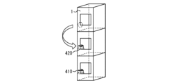
- the first beacon terminal 410 and the second beacon terminal 420 are arranged vertically in the elevator 1 in real space. That is, the first beacon terminal 410 and the second beacon terminal 420 have different vertical positions and the same horizontal position in real space.
- the first beacon terminal 410 and the second beacon terminal 420 determine the Z-axis direction. Also, for example, the first beacon terminal 410 determines the coordinate origin.
- the user wearing the AR glasses 300 first moves to a position where the first beacon terminal 410 is within the field of view of the camera 304.
- the coordinate alignment unit 321 uses the reception strength of the first beacon signal, etc. to identify the position of the AR glasses 300 relative to the first beacon terminal 410 in real space.
- the coordinate alignment unit 321 aligns the reference position indicated by the first beacon terminal 410 in the real space and the image. This aligns the coordinate origin.
- the coordinate alignment unit 321 aligns the reference position indicated by the second beacon terminal 420 in the real space and in the image. As described above, the first beacon terminal 410 and the second beacon terminal 420 are aligned vertically within the elevator shaft 1 in the real space. Therefore, the coordinate alignment unit 321 can determine the Z-axis direction from the reference positions indicated by the first beacon terminal 410 and the second beacon terminal 420, respectively.
- the first beacon terminal 410 and the second beacon terminal 420 are arranged vertically in the elevator shaft 1 in real space. On the premise of this, even if only one of the first beacon terminal 410 and the second beacon terminal 420 is within the field of view of the camera 304 and the other is outside the field of view of the camera 304, the Z-axis direction can be identified if the AR glasses 300 can receive a beacon signal from the other beacon terminal.
- the coordinate alignment unit 321 can identify the Z-axis direction using the reception strength of the first beacon signal and the second beacon signal, etc.
- the X-axis direction is specified, for example, using the horizontal arrangement in real space.
- the coordinate alignment unit 321 aligns the X-axis in the image with the lower edge of the opening of the elevator shaft 1, which serves as the entrance/exit for the landing side.
- the remaining Y-axis direction can be specified as a direction perpendicular to both the X-axis and Z-axis directions. In this way, the coordinate alignment unit 321 performs coordinate alignment to match the position in the elevator shaft 1 in real space with the position on the coordinate axis of the coordinate data obtained from the data management unit.
- the display control unit 320 causes the display unit 302 to display an augmented reality image generated by superimposing the three-dimensional model data of the object on an image of the interior of the elevator shaft 1 in real space.
- the display control unit 320 generates an augmented reality image by superimposing the three-dimensional model data of the object acquired by the data acquisition unit 312 on an image of the interior of the elevator shaft 1 in real space acquired by the image acquisition unit 311.
- the display control unit 320 then causes the display unit 302 to display the generated augmented reality image.
- the display unit 302 displays an augmented reality image in which the three-dimensional model data of the object acquired from the data management unit 202 is superimposed on an image of the interior of the elevator shaft 1 in real space.
- the display control unit 320 can correctly superimpose the three-dimensional model data of the object on the image of the interior of the elevator shaft 1 in real space by using the coordinate axes aligned by the coordinate alignment unit 321.
- the display control unit 320 also changes the generated augmented reality image in response to the behavior of the AR glasses 300 detected by the behavior detection unit 315, i.e., changes in the position and orientation of the display unit 302 provided on the AR glasses 300.
- the display unit 302 changes the augmented reality image it displays in response to changes in the position and orientation of the display unit 302. This makes it possible to display on the display unit 302 an augmented reality image that matches the field of view that would be visible to the user if the user were not wearing the AR glasses 300, in response to the movement, orientation, posture, etc. of the user wearing the AR glasses 300.
- the operation detection unit 313 detects a selection operation for individually selecting an object in an augmented reality image and a movement operation for a selected object.
- the user can perform a selection operation and a movement operation, for example, by operating the operation unit 303 of the AR glasses 300.
- a selection operation is an operation for individually selecting an object in an augmented reality image displayed on the display unit 302.
- a movement operation is an operation for moving an object selected by the selection operation within the augmented reality image displayed on the display unit 302.
- the operation detection unit 313 detects a selection operation for individually selecting an object in an augmented reality image and a movement operation for a selected object.
- the update unit 314 updates the three-dimensional model data of the object to reflect the changes in the orientation and position of the object due to the move operation. Updating refers to saving new information at the time of execution without overwriting past information. After the revision is completed, unnecessary information may be deleted.
- the update unit 314 updates the three-dimensional model data of the object that has been moved to data of the orientation and position of the object after it has been moved. Note that if the object that has been moved is something that can be deformed, such as a flexible wiring, for example, the update unit 314 updates the orientation and position of the three-dimensional model data of the object as well as its shape to that after the move operation.
- the glass communication unit 301 acquires the three-dimensional model data of the object updated by the update unit 314.
- the glass communication unit 301 then transmits the updated three-dimensional model data of the object to the cloud server 200.
- the server communication unit 201 of the cloud server 200 receives the three-dimensional model data of the object transmitted from the AR glass 300.
- the glass communication unit 301 also transmits images stored in the glass storage unit 306 to the cloud server 200.
- the server communication unit 201 of the cloud server 200 receives images transmitted from the AR glass 300.
- the data management unit 202 of the cloud server 200 updates the stored three-dimensional model data to the three-dimensional model data received by the server communication unit 201.
- the glass communication unit 301 is a transmission unit that transmits the updated three-dimensional model data of the object to the data management unit 202.
- the elevator shaft equipment layout support system configured as described above, it is possible to check before installation whether each piece of equipment specified in the 3D model data created at the time of design can be placed as specified on-site. If the equipment cannot be placed as specified, the 3D model data can be manipulated on the spot to change the layout to an optimal layout that takes into account the on-site conditions, and the changes can be reflected in the 3D model data.
- This allows on-site workers to easily check the layout of equipment, etc. to be installed in the elevator hoistway that was designed in advance, and also makes it easy to modify the 3D model data of equipment, etc. according to the actual conditions in the hoistway, thereby supporting the work of placing equipment in the hoistway.
- the glasses processing unit 310 may further include a gesture detection unit 316, as shown in FIG. 2.
- a user wearing the AR glasses 300 can hold out their hand in front of themselves, allowing the camera 304 of the AR glasses 300 to capture an image of the user's hand.
- the user's hand may be a bare hand, or may be a hand wearing, for example, a work glove or the like.
- the gesture detection unit 316 detects a gesture of the user's hand captured by the camera 304.
- the gesture detection unit 316 extracts the user's hand from the image captured by the camera 304.
- the gesture detection unit 316 detects a gesture made by the extracted user's hand.
- the operation detection unit 313 can detect a selection operation and a movement operation by a gesture.
- the operation detection unit 313 determines whether or not the gesture detected by the gesture detection unit 316 is a specific gesture that represents a selection operation and a movement operation, respectively. Then, if the gesture detected by the gesture detection unit 316 is a specific gesture that represents a selection operation, the operation detection unit 313 detects the selection operation. Also, if the gesture detected by the gesture detection unit 316 is a specific gesture that represents a movement operation, the operation detection unit 313 detects the movement operation.
- a gesture representing a selection operation is the action of pointing with a finger at an object in an augmented reality image.
- a gesture representing a movement operation is the action of dragging the selected object within the augmented reality image. In this way, the user can intuitively perform selection and movement operations while viewing the augmented reality image.
- the update unit 314 updates the three-dimensional model data of the object to reflect the change in orientation and position of the first object due to the move operation, and updates the three-dimensional model data of the second object to reflect the change in orientation and position of a second object associated with the first object due to the move operation on the first object.
- the first object is a control panel
- an example of the second object associated with it would be wiring connected to the control panel.
- the glass processing unit 310 may further include a model data generation unit 317 as shown in FIG. 2.
- the model data generation unit 317 detects an object from an image of the elevator shaft 1 in real space and generates three-dimensional model data of the object.
- the display control unit 320 generates an augmented reality image by superimposing the three-dimensional model data of the object acquired from the data management unit 202 and the three-dimensional model data of the object generated by the model data generation unit 317 on the image of the elevator shaft 1 in real space.
- the display unit 302 displays an augmented reality image generated by superimposing the three-dimensional model data of the object acquired from the data management unit 202 and the three-dimensional model data of the object generated by the model data generation unit 317 on the image of the elevator shaft 1 in real space.
- the object can be easily captured as three-dimensional model data.
- This kind of data reflecting the actual conditions inside the elevator shaft 1 can be used not only when installing an elevator, but also when remodeling or modernizing the elevator.
- the glasses processing unit 310 may further include a distance measurement unit 318 as shown in FIG. 2.
- the distance measurement unit 318 measures the distance between objects in the augmented reality image. Specifically, for example, when one object is selected by a selection operation and another object is further selected by a selection operation, the distance measurement unit 318 measures the distance between the two selected objects.
- the distance measurement unit 318 can calculate the distance between the objects based on, for example, three-dimensional model data of these objects. In this way, a user wearing the AR glasses 300 can easily check the distance between devices, wiring, etc. to be installed at the work site. This makes it easy to ensure clearance between devices, and improves work efficiency, etc.
- the display unit 302 may be capable of displaying attribute information of an object superimposed on an augmented reality image.
- the attribute information of an object is the type, name, material, color, etc. of the object.
- the display unit 302 may also be capable of displaying numerical information of three-dimensional model data of the object superimposed on an augmented reality image. In this way, a user wearing the AR glasses 300 can easily check information on the equipment, wiring, etc. to be installed at the work site. This can improve work efficiency, etc.
- the glass processing unit 310 may further include an attribute information acquisition unit 319 as shown in FIG. 2.
- the attribute information acquisition unit 319 inputs attribute information of an object.
- a user can input attribute information of an object by selecting an object in an augmented reality image and operating the operation unit 303 or a gesture.
- the attribute information acquisition unit 319 acquires the attribute information of the object thus input.
- the display unit 302 may display the attribute information of the object acquired by the attribute information acquisition unit 319 by superimposing it on the augmented reality image.
- the glass communication unit 301 may transmit the attribute information of the object acquired by the attribute information acquisition unit 319 to the cloud server 200.
- the data management unit 202 may store the attribute information of the object received by the server communication unit 201 in association with the three-dimensional model data of the object.
- one of the BIM data generation unit 111 and the two-dimensional drawing data generation unit 112 may be further provided.
- the terminal processing unit 110 of the terminal device 100 is provided with the BIM data generation unit 111 and the two-dimensional drawing data generation unit 112.
- the BIM data generation unit 111 and the two-dimensional drawing data generation unit 112 are not limited to being provided in the terminal device 100.
- the BIM data generation unit 111 and the two-dimensional drawing data generation unit 112 may also be provided in the cloud server 200, the AR glasses 300, etc.
- the BIM data generation unit 111 generates BIM (Building Information Modeling) data from the three-dimensional model data of the object.
- the server communication unit 201 of the cloud server 200 transmits the coordinate data in the elevator shaft 1 and the three-dimensional model data of the object installed in the elevator shaft 1 stored in the data management unit 202 to the terminal device 100.
- the terminal communication unit 101 of the terminal device 100 receives the coordinate data and the three-dimensional model data transmitted from the cloud server 200.
- the BIM data generation unit 111 generates BIM data from the coordinate data and the three-dimensional model data received by the terminal communication unit 101.
- the two-dimensional drawing data generating unit 112 also generates two-dimensional drawing data from three-dimensional model data of the object.
- the two-dimensional drawing data generating unit 112 acquires coordinate data within the elevator shaft 1 and three-dimensional model data of objects to be installed within the elevator shaft 1, which are stored in the data management unit 202 of the cloud server 200, and generates two-dimensional drawing data from the acquired coordinate data and three-dimensional model data.
- two-dimensional drawing data that reflects the on-site situation can be generated from three-dimensional data as necessary, and drawings that reflect the on-site situation can be provided to contractors, clients, architectural firms, etc. involved in the construction of buildings, including the installation of elevators.
- drawings to be attached to documents submitted in procedures prescribed by law can be easily created.
- step S100 the AR glasses 300, the first beacon terminal 410, and the second beacon terminal 420 are powered on.
- step S101 as shown in FIG. 5, the glass communication unit 301 of the AR glasses 300 starts communication and connects to the Internet.
- step S102 the display control unit 320 of the AR glasses 300 causes the display unit 302 to display a main operation screen (menu screen).
- a main operation screen An example of the main operation screen displayed on the display unit 302 is shown in FIG. 6.
- pressing the "menu" button allows, for example, the selection of a beacon terminal, the determination of the position of a beacon terminal, the cancellation of a beacon terminal position that has already been determined, the display of a help screen, and the like.
- the elevator shaft equipment layout support system then performs the process of step S103.
- step S103 the glass processing unit 310 determines whether the property in which the elevator shaft 1 of the target elevator is to be installed and the elevator number have been specified by operation of the operation unit 303 or gesture. If the property and the elevator number have not been specified, the glass processing unit 310 returns to step S102 and continues processing. On the other hand, if the property and the elevator number have been specified, the glass processing unit 310 then performs processing of step S104.
- step S104 the display control unit 320 of the AR glasses 300 causes the display unit 302 to display a beacon terminal (indoor positioning device) setting screen.
- a beacon terminal indoor positioning device
- FIG. 7 An example of the beacon terminal setting screen displayed on the display unit 302 is shown in FIG. 7.
- the glass processing unit 310 judges whether or not a beacon terminal has been detected, that is, whether or not the glass communication unit 301 has received a beacon signal transmitted from the beacon terminal, based on the received reception strength. If a beacon terminal is not detected, the glass processing unit 310 returns to step S104 and continues processing. On the other hand, if a beacon terminal is detected, the glass processing unit 310 then performs processing in step S106.
- step S106 the display control unit 320 of the AR glasses 300 causes the display unit 302 to display a beacon terminal (indoor positioning device) selection screen.
- a beacon terminal indoor positioning device
- FIG. 8 An example of the beacon terminal selection screen displayed on the display unit 302 is shown in FIG. 8.
- the display control unit 320 of the AR glasses 300 causes the display unit 302 to display three-dimensional coordinate data for the interior of the elevator shaft 1.
- the glass communication unit 301 accesses the cloud server 200 and requests coordinate data within the elevator shaft 1.
- the server communication unit 201 of the cloud server 200 acquires the coordinate data within the elevator shaft 1 stored in the data management unit 202 and transmits it to the AR glasses 300.
- the display control unit 320 then causes the display unit 302 to display the three-dimensional coordinate data within the elevator shaft 1 received by the glass communication unit 301.
- An example of a three-dimensional coordinate data display screen displayed on the display unit 302 is shown in FIG. 10.
- the glass processing unit 310 then performs the process of step S108.
- step S108 the position of the beacon terminal is specified in the three-dimensional coordinate data in the elevator shaft 1 displayed on the display unit 302, for example, as shown in FIG. 11. Then, in the following step S109, the glass processing unit 310 determines whether or not the positions in real space and the positions in the three-dimensional coordinate data match for all beacon terminals selected in step S106. If the positions in real space and the positions in the three-dimensional coordinate data do not match for all beacon terminals, the glass processing unit 310 returns to step S106 and continues processing. On the other hand, if the positions in real space and the positions in the three-dimensional coordinate data match for all beacon terminals, the series of beacon terminal position identification processes is completed.
- step S200 the site worker (user) moves to the floor on which the second beacon terminal 420 is installed.
- step S201 the user, near the second beacon terminal 420, checks again the position of the second beacon terminal 420 in real space and in the three-dimensional coordinate data, and corrects the position designation if necessary. Then, once the correction is complete, the glass processing unit 310 next performs the process of step S202.
- step S202 the image acquisition unit 311 acquires an image of the landing opening of the elevator shaft 1 captured by the camera 304.
- the coordinate alignment unit 321 acquires detection axis information of the sensor 305 ( Figure 14).
- the coordinate alignment unit 321 adjusts the coordinate origin and the Z-axis direction of the sensor 305 based on the reference position indicated by the beacon terminal.
- the coordinate alignment unit 321 also aligns the X-axis direction of the sensor 305 with the lower edge of the image of the landing opening of the elevator shaft 1 ( Figure 15). In this way, the coordinate alignment unit 321 corrects the detection axes (X-axis, Y-axis, and Z-axis) of the sensor 305.
- the glass processing unit 310 determines in the following step S301 whether or not three-dimensional data display has been selected by operation of the operation unit 303 or gesture (FIG. 17). If three-dimensional data display has been selected, the glass processing unit 310 then performs the process of step S302.
- step S302 the glass communication unit 301 accesses the cloud server 200 and requests three-dimensional model data of the object.
- the server communication unit 201 of the cloud server 200 acquires the three-dimensional model data of the object stored in the data management unit 202 and transmits it to the AR glasses 300.
- the display control unit 320 then aligns the position and orientation in which the three-dimensional model data of the object received by the glass communication unit 301 is displayed to the aligned coordinates.
- the display control unit 320 causes the display unit 302 to display an augmented reality image generated by superimposing the three-dimensional model data of the object on an image of the interior of the elevator shaft 1 in real space. This makes it possible to display an augmented reality image in which the three-dimensional model data of the object is superimposed on an image of the interior of the elevator shaft 1 in real space in accordance with the behavior of the user wearing the AR glasses 300.
- an augmented reality image is displayed that virtually reproduces the situation in which various devices, wiring, etc., to be installed on the front wall of the hoistway 1 are actually installed, according to the user's field of view at that time.
- an augmented reality image is displayed that virtually reproduces the situation in which various devices, wiring, etc., to be installed on the landing side of the hoistway 1 are actually installed, according to the user's field of view at that time.
- step S400 an augmented reality image in which three-dimensional model data of the object is superimposed on an image of the inside of the elevator shaft 1 in real space is displayed on the display unit 302 of the AR glasses 300.
- step S401 the user checks through the AR glasses 300 whether objects such as equipment and wiring do not interfere with each other. Then, in step S402, the user determines whether no interfering equipment, wiring, etc. are found and the current design arrangement is possible. If the current design arrangement is possible, the process ends. On the other hand, for example, if interfering equipment, wiring, etc. are found as shown in FIG. 21, the glasses processing unit 310 then performs the process of step S403.
- step S403 the user operates the operation menu displayed on the display unit 302 by the display control unit 320 to select a three-dimensional data operation (FIG. 22).
- the user then performs an object selection operation in the augmented reality image to select an object to be moved to eliminate interference (FIG. 23).
- the display control unit 320 displays the movable range of the selected object in the augmented reality image.
- the movable range of the selected object can be determined, for example, by the excess length range of the wiring connected to the object.
- the glass processing unit 310 then performs the process of step S404.
- step S404 the user moves the object within the augmented reality image.
- the display control unit 320 determines whether the moved object is within the movable range of the object (the excess length range of the connected wiring). If the moved object is within the movable range of the object, the glass processing unit 310 then performs processing in step S406.
- the display control unit 320 generates an augmented reality image after the object has been moved, and displays it on the display unit 302 ( Figure 24).
- the update unit 314 then updates the 3D model data of the moved object to reflect the state of the object after the move operation.
- step S500 when the placement of an object (device, wiring, etc.) is changed, the glass processing unit 310 then performs the process of step S501.
- step S501 the user checks and identifies the placement, size, and material of the obstacle that caused the change in placement of the object in the augmented reality image or the like displayed on the display unit 302.
- step S503 when the user operates to select "add/delete 3D data" in the operation menu displayed on the display unit 302 by the display control unit 320, in step S503, the user inputs information such as the size and material of the obstacle in the augmented reality image (FIG. 26). After step S503, the glass processing unit 310 then performs the process of step S504.
- step S504 the display control unit 320 generates an augmented reality image in which an obstacle object is additionally arranged based on the information input in step S503, and displays the image on the display unit 302 (FIG. 27). Then, when two objects including the added obstacle are selected in the augmented reality image, the distance measurement unit 318 measures the distance between the two objects including the obstacle. The display control unit 320 displays the distance between the obstacle and the object on the display unit 302 (FIG. 28). This allows the user to check whether the distance between the obstacle and the object meets the necessary clearance conditions. Then, in the following step S505, if the user performs a confirmation operation, the series of object addition processes ends. Note that the addition of an object in step S503 may be performed by the model data generation unit 317 detecting an obstacle from an image of the elevator shaft 1 in real space and generating three-dimensional model data of the obstacle, as shown in FIG. 29.
- step S600 a user wearing AR glasses 300 looks around inside the elevator shaft 1 and confirms the contents of the changed augmented reality image displayed on the display unit 302. Then, in the following step S601, if the objects displayed in the changed augmented reality image are able to be placed in the position they are shown in, the series of confirmation processes ends. On the other hand, if the objects displayed in the changed augmented reality image are still not able to be placed in the position they are shown in (step S602), the process of moving the objects in the augmented reality image (FIG. 20) and the process of adding the object such as an obstacle that caused the position change (FIG. 25) are performed again.
- step S700 if there is another work site, in step S701, a beacon terminal is installed at the other work site as necessary. Note that since improved positioning accuracy can be expected by installing the beacon terminal as close to the work site as possible, it is desirable to install the beacon terminal at the other work site. In this case, for example, as shown in FIG. 33, the second beacon terminal 420 installed at the previous work site may be moved, or as shown in FIG. 34, a new third beacon terminal 430 may be added and installed.
- steps S702 to S707 the object placement is confirmed and corrected using the augmented reality image, in the same way as at the previous work site. That is, in step S702, a process of identifying the beacon terminal position (FIG. 4) is performed, and in the following step S703, a coordinate alignment process (FIG. 12) is performed. Then, in the following step S704, a process of displaying the augmented reality image including the object (FIG. 16) is performed, and in the following step S705, a process of moving the object within the augmented reality image (FIG. 20) is performed. Then, in the following step S706, a process of adding an object such as an obstacle that caused the placement change (FIG. 25) is performed, and in the following step S707, a process of confirming the changes (FIG. 30) is performed.
- step S700 determines whether there are no other work sites and work at all sites has been completed. If it is determined in step S700 that there are no other work sites and work at all sites has been completed, the elevator shaft equipment layout support system then performs the process of step S708. If there is a revision by the user in step S708, the glasses communication unit 301 transmits the three-dimensional model data of the object updated by the update unit 314 and the user's revision instructions to the cloud server 200. Then, the server communication unit 201 of the cloud server 200 receives the three-dimensional model data of the object transmitted from the AR glasses 300 (step S709).
- step S710 the data management unit 202 of the cloud server 200 updates the stored three-dimensional model data to the three-dimensional model data received by the server communication unit 201.
- step S711 the data management unit 202 temporarily stores the three-dimensional model data until the revision process is performed.
- step S800 the user displays and views the 3D model data. Then, in the following step S801, if the revised 3D model data does not contain any description of the revision content and revision history, in step S802, the user adds the revision content and revision history to the revised 3D model data.
- This revision process may be performed using a PC or the like at the work site or a location separate from the work site, as shown in FIG. 36, for example.
- the revision process may be performed by a user wearing AR glasses 300 at the work site checking an augmented reality image on which the revised three-dimensional model data is superimposed.
- the elevator shaft equipment layout support system further includes an indoor positioning device 400.
- the indoor positioning device 400 is a parent device of the beacon terminal.
- a first beacon terminal 410 and a second beacon terminal 420 are provided as child devices.
- the indoor positioning device 400 includes a positioning device communication unit 401, a positioning device processing unit 402, and a positioning device storage unit 403.
- the first beacon terminal 410 includes a first beacon communication unit 412.
- the second beacon terminal 420 includes a second beacon communication unit 422.
- the indoor positioning device 400 and the first beacon terminal 410 can communicate via the positioning device communication unit 401 and the first beacon communication unit 412.
- the indoor positioning device 400 and the second beacon terminal 420 can communicate via the positioning device communication unit 401 and the second beacon communication unit 422.
- the indoor positioning device 400 and the AR glasses 300 can communicate via the positioning device communication unit 401 and the glasses communication unit 301.
- the indoor positioning device 400 and the cloud server 200 can communicate via the positioning device communication unit 401 and the server communication unit 201.
- the first beacon terminal 410 and the second beacon terminal 420 are each capable of transmitting a beacon signal.
- the first beacon terminal 410 and the second beacon terminal 420 transmit and stop transmitting beacon signals according to a control signal transmitted from the indoor positioning device 400.
- the indoor positioning device 400 which is the parent device, controls the operation of the first beacon terminal 410 and the second beacon terminal 420, which are child devices.
- the positioning device processing unit 402 of the indoor positioning device 400 realizes some or all of the functions of the image acquisition unit 311, data acquisition unit 312, operation detection unit 313, update unit 314, behavior detection unit 315, gesture detection unit 316, model data generation unit 317, distance measurement unit 318, attribute information acquisition unit 319, display control unit 320, and coordinate alignment unit 321 described above.
- the positioning device communication unit 401 of the indoor positioning device 400 realizes the function of the transmission unit described above.
- the glass memory unit 306 and glass processing unit 310 are not provided in the AR glasses 300. Therefore, the positioning device processing unit 402 of the indoor positioning device 400 realizes the functions of all of the units described above.
- the glass memory unit 306 and glass processing unit 310 may be provided in the AR glasses 300, and only some of the functions of the units described above may be provided in the indoor positioning device 400.
- the indoor positioning device 400 includes some or all of the image acquisition unit 311, data acquisition unit 312, operation detection unit 313, and update unit 314, as well as the aforementioned transmission unit. This makes it possible to distribute the load associated with relatively high-load three-dimensional data processing, etc., and reduce the processing load on the glass processing unit 310 of the AR glasses 300. This can contribute to making the AR glasses 300 smaller and lighter.
- the elevator shaft equipment layout support system may or may not include the terminal device 100.
- the terminal processing unit 110 of the terminal device 100 may be provided with some or all of the functions described below that are provided in the glass processing unit 310 of the AR glasses 300. In this way, the data processing load can be distributed, and the processing load on the glass processing unit 310 of the AR glasses 300 can be reduced. This can contribute to making the AR glasses 300 smaller and lighter.
- the elevator shaft equipment layout support system further includes VR glasses 500.
- Fig. 39 shows an example of a configuration of the second variant of the elevator shaft equipment layout support system.
- the elevator shaft equipment layout support system includes a cloud server 200, AR glasses 300, and VR glasses 500.
- the VR glasses 500 are glasses-type or helmet-type devices worn on the user's face or head. VR is an abbreviation for "Virtual Reality.”
- the VR glasses 500 are basically configured with the camera 304 removed from the AR glasses 300. Although not shown here, the VR glasses 500 may be equipped with a camera that captures the movement of the user's eyeballs as a function other than the camera 304. This function plays the role of the VR glasses operation unit 520 described later.
- the VR glasses 500 are equipped with a glass communication unit 301, a display unit 302, a sensor 305, a glass memory unit 306, and a VR glass processing unit 510.
- the glass communication unit 301, the display unit 302, the sensor 305, and the glass memory unit 306 of the VR glasses 500 each have the same functions as the glass communication unit 301, the display unit 302, the sensor 305, and the glass memory unit 306 of the AR glasses 300, respectively.
- the VR glass operation unit 520 is provided as an accessory to the VR glasses 500.
- the VR glass operation unit 520 corresponds to the operation unit 303 of the AR glasses 300.
- the VR glass operation unit 520 is, for example, a remote controller, a button, a switch, a stick, a touch pad, etc., which allows the user to operate the VR glasses 500 and input various information.
- the user of the VR glasses 500 does not need to be in the real elevator shaft 1, and is usually in a location different from the real elevator shaft 1. Because of this, the user of the VR glasses 500 does not need to move around much, and communication between the VR glasses 500 and the cloud server 200 may be wired or wireless. Note that communication between the VR glasses 500 and the cloud server 200 may be via a communication network such as the Internet.
- the glass memory unit 306 of the VR glasses 500 stores various data related to the operational control of the VR glasses 500.
- the glass memory unit 306 of the VR glasses 500 stores coordinate data of the interior of the elevator shaft 1 and three-dimensional model data of objects transmitted from the cloud server 200.
- an image of the interior of the elevator shaft 1 captured by a camera may be transmitted from the cloud server 200 to the VR glasses 500.
- the glass memory unit 306 of the VR glasses 500 further stores the image of the interior of the elevator shaft 1 transmitted from the cloud server 200.
- the VR glass processing unit 510 has the function of performing calculations and the like using data stored mainly in the glass memory unit 306 of the VR glass 500, and executing predetermined processing required for controlling the operation of the VR glass 500. As shown in FIG. 40, the VR glass processing unit 510 has, as its functional configuration, a data acquisition unit 312, a behavior detection unit 315, a display control unit 320, an operation detection unit 313, and an update unit 314.
- the functions of the data acquisition unit 312 and behavior detection unit 315 of the VR glasses processing unit 510 are equivalent to the functions of the data acquisition unit 312 and behavior detection unit 315 of the AR glasses 300.
- the display control unit 320 of the VR glasses processing unit 510 causes the display unit 302 of the VR glasses 500 to display a virtual reality image generated based on the three-dimensional model data of the object.
- the display control unit 320 of the VR glasses processing unit 510 generates a virtual reality image based on the three-dimensional model data of the object acquired by the data acquisition unit 312 of the VR glasses processing unit 510.
- the display control unit 320 of the VR glasses processing unit 510 then causes the display unit 302 of the VR glasses 500 to display the generated virtual reality image. In this way, the display unit 302 of the VR glasses 500 displays the virtual reality image generated based on the three-dimensional model data of the object acquired from the data management unit 202.
- the display control unit 320 of the VR glasses processing unit 510 also changes the virtual reality image it generates in response to the behavior of the VR glasses 500 detected by the behavior detection unit 315 of the VR glasses processing unit 510, i.e., changes in the position and orientation of the display unit 302 provided on the VR glasses 500. That is, the display unit 302 of the VR glasses 500 changes the virtual reality image it displays in response to changes in the position and orientation of the display unit 302. This makes it possible to display on the display unit 302 of the VR glasses 500 a virtual reality image that matches the field of view of the user wearing the VR glasses 500 in response to the movement, orientation, posture, etc. of the user.
- the operation detection unit 313 of the VR glasses processing unit 510 detects a selection operation for individually selecting an object in a virtual reality image and a movement operation for a selected object.
- the user can perform a selection operation and a movement operation, for example, by operating the VR glasses operation unit 520.
- a selection operation is an operation for individually selecting an object in a virtual reality image displayed on the display unit 302 of the VR glasses 500.
- a movement operation is an operation for moving an object selected by a selection operation within the virtual reality image displayed on the display unit 302 of the VR glasses 500.
- the operation detection unit 313 of the VR glasses processing unit 510 detects a selection operation for individually selecting an object in a virtual reality image and a movement operation for a selected object.
- the update unit 314 of the VR glasses processing unit 510 updates the 3D model data of the object to reflect changes in the orientation and position of the object due to the movement operation. Updating refers to saving new information at the time of execution without overwriting past information. After the revision is completed, unnecessary information may be deleted.
- the update unit 314 updates the 3D model data of the object that has been moved to data of the orientation and position of the object after the movement. Note that if the object that has been moved is something that can be deformed, such as a flexible wiring, the update unit 314 updates the orientation and position of the 3D model data of the object as well as the shape to that after the movement operation.
- the glass communication unit 301 of the VR glass processing unit 510 acquires the three-dimensional model data of the object updated by the update unit 314 of the VR glass processing unit 510. Then, the glass communication unit 301 of the VR glass processing unit 510 transmits the updated three-dimensional model data of the object to the cloud server 200.
- the server communication unit 201 of the cloud server 200 receives the three-dimensional model data of the object transmitted from the VR glass 500.
- the data management unit 202 of the cloud server 200 updates the stored three-dimensional model data to the three-dimensional model data received by the server communication unit 201.
- the data managed by the data management unit 202 may include images captured by a site worker using a camera.
- the data acquisition unit 312 of the VR glass processing unit 510 may further acquire images of the inside of the hoistway 1 from the data management unit 202 of the cloud server 200.
- the server communication unit 201 of the cloud server 200 transmits the images of the inside of the hoistway 1 stored in the data management unit 202 to the VR glasses 500.
- the glass communication unit 301 of the VR glasses 500 receives the images of the inside of the hoistway 1 transmitted from the cloud server 200.
- the data acquisition unit 312 of the VR glass processing unit 510 acquires the images of the inside of the hoistway 1 received by the glass communication unit 301 of the VR glass processing unit 510.
- the display control unit 320 of the VR glasses processing unit 510 may display on the display unit 302 of the VR glasses 500 a virtual reality image generated by superimposing the three-dimensional model data of the object on an image of the interior of the elevator shaft 1 in the virtual space.
- the display control unit 320 of the VR glasses processing unit 510 generates a virtual reality image by superimposing the image of the interior of the elevator shaft 1 in the real space acquired by the data acquisition unit 312 of the VR glasses processing unit 510 on the three-dimensional model data of the object.
- the display control unit 320 of the VR glasses processing unit 510 displays the generated virtual reality image on the display unit 302 of the VR glasses 500.
- the display unit 302 of the VR glasses 500 displays a virtual reality image in which the three-dimensional model data of the object acquired from the data management unit 202 is superimposed on an image of the interior of the elevator shaft 1 in the real space.
- the VR glasses processing unit 510 may have a model data generation unit 317 as shown in FIG. 40.
- the model data generation unit 317 of the VR glasses processing unit 510 has the same function as the model data generation unit 317 of the AR glasses 300.
- a virtual reality image including an image of the inside of the elevator 1 in real space
- an augmented reality image is displayed with coordinate alignment on the display unit 302 of the glasses worn by a user who is in the elevator 1 in real space.
- the user of the glasses on which the display unit 302 displays the virtual reality image does not need to be in the elevator 1 in real space, and therefore there is no need for coordinate alignment.
- the VR glass processing unit 510 in this second modified example may have a distance measurement unit 318, as shown in FIG. 40.
- the distance measurement unit 318 of the VR glass processing unit 510 has the same function as the distance measurement unit 318 of the AR glass 300. In other words, the distance measurement unit 318 of the VR glass processing unit 510 measures the distance between objects in a virtual reality image.
- the display unit 302 of the VR glasses 500 in this second modified example may be capable of displaying attribute information of an object superimposed on a virtual reality image.
- the display unit 302 of the VR glasses 500 may be capable of displaying numerical information of three-dimensional model data of an object superimposed on a virtual reality image.
- the glass processing unit 310 has an attribute information acquisition unit 319 as shown in FIG. 40.
- the attribute information acquisition unit 319 has the same function as the attribute information acquisition unit 319 of the AR glasses 300.
- step S900 a beacon terminal is installed at the work site.
- step S901 a process of identifying the beacon terminal position (FIG. 4) is performed, and in step S902, a coordinate alignment process (FIG. 12) is performed.
- step S903 if the designer's support is not required for the equipment placement change process, in step S904, a display process (FIG. 16) of an augmented reality image including an object is performed on the display unit 302 of the AR glasses 300 worn by the site worker, and in the following step S905, a process of moving the object within the augmented reality image (FIG. 20) is performed.
- step S906 a process of adding an object such as an obstacle that caused the placement change (FIG. 25) is performed, and in the following step S907, a process of confirming the change content (FIG. 30) is performed.
- step S903 support from the designer is required for the device layout change process
- step S908 as shown in FIG. 42
- a virtual reality image including the object is displayed on the display unit 302 of the VR glasses 500 worn by the designer, and in the following step S909, the object is moved within the virtual reality image.
- an object is added, such as an obstacle that caused the layout change, and in step S907, the change content is confirmed.
- VR glasses 500 can support the equipment placement work at the work site or at a location different from the work site.
- multiple AR glasses 300 may be used, and virtual reality images may be displayed on the AR glasses 300 instead of the VR glasses 500.
- FIG. 43 is a diagram showing an example of a configuration for implementing the functions of the device processing unit 110, the glass processing unit 310, the positioning device processing unit 402, and the VR glass processing unit 510 in this embodiment.
- the device processing unit 110, the glass processing unit 310, the positioning device processing unit 402, and the VR glass processing unit 510 will not be differentiated from one another and will simply be referred to as processing units.
- the functions of the processing unit are realized, for example, by a processing circuit.
- the processing circuit may include a processor 601 and a memory 602.
- the processing circuit may be dedicated hardware 603. A part of the processing circuit may be formed as dedicated hardware 603, and the processing circuit may further include a processor 601 and a memory 602.
- the processing circuit may also include a device that combines the processor 601 and the memory 602. In the example shown in the figure, a part of the processing circuit is formed as dedicated hardware 603. In the example shown in the figure, the processing circuit further includes a processor 601 and a memory 602.
- a processing circuit part of which is at least one dedicated hardware 603, may be, for example, a single circuit, a composite circuit, a programmed processor, a parallel programmed processor, an ASIC, an FPGA, or a combination of these.
- the processing circuit comprises at least one processor 601 and at least one memory 602
- the functions of the processing unit are realized by software, firmware, or a combination of software and firmware.
- Processor 601 realizes the functions of each part by reading and executing the programs stored in memory 602.
- Processor 601 is also called a CPU (Central Processing Unit), GPU (Graphics Processing Unit), GPGPU (General-Purpose computing on Graphics Processing Units), TPU (Tensor Processing Unit), central processing unit, processing unit, arithmetic unit, microprocessor, microcomputer, or DSP.
- Memory 602 may be, for example, a non-volatile or volatile semiconductor memory such as a RAM, a ROM, a flash memory, an EPROM, or an EEPROM, or a magnetic disk, a flexible disk, an optical disk, a compact disk, a mini disk, a DVD, etc.
- the processing circuit of the processing unit can realize each function of the processing unit by hardware, software, firmware, or a combination of these.
- the processing circuit of the processing unit has at least a processor 601 and a memory 602, the processor 601 executes a program stored in the memory 602 in the processing unit, and the hardware and software of the processing unit work together to realize the functions of each part of the processing unit.
- This disclosure can be used in an elevator shaft equipment layout support system that supports the layout design of various devices, wiring, etc. within an elevator shaft.
- Elevator shaft 100 Terminal device 101 Terminal communication unit 110 Terminal processing unit 111 BIM data generation unit 112 2D drawing data generation unit 103 Human interface unit 200 Cloud server 201 Server communication unit 202 Data management unit 300 AR glasses 301 Glass communication unit 302 Display unit 303 Operation unit 304 Camera 305 Sensor 306 Glass storage unit 310 Glass processing unit 311 Image acquisition unit 312 Data acquisition unit 313 Operation detection unit 314 Update unit 315 Behavior detection unit 316 Gesture detection unit 317 Model data generation unit 318 Distance measurement unit 319 Attribute information acquisition unit 320 Display control unit 321 Coordinate alignment unit 400 Indoor positioning device 401 Positioning device communication unit 402 Positioning device processing unit 403 Positioning device storage unit 410 First beacon terminal 411 First beacon transmission unit 412 First beacon communication unit 420 Second beacon terminal 421 Second beacon transmission unit 422 Second beacon communication unit 430 Third beacon terminal 500 VR glasses 510 VR glasses processing unit 520 VR glasses operation unit 601 Processor 602 Memory 603 Dedicated hardware
Landscapes
- Indicating And Signalling Devices For Elevators (AREA)
Priority Applications (3)
| Application Number | Priority Date | Filing Date | Title |
|---|---|---|---|
| CN202380102327.7A CN121969565A (zh) | 2023-10-06 | 2023-10-06 | 井道内设备配置辅助系统 |
| PCT/JP2023/036635 WO2025074641A1 (ja) | 2023-10-06 | 2023-10-06 | 昇降路内機器配置支援システム |
| JP2025550729A JPWO2025074641A1 (https=) | 2023-10-06 | 2023-10-06 |
Applications Claiming Priority (1)
| Application Number | Priority Date | Filing Date | Title |
|---|---|---|---|
| PCT/JP2023/036635 WO2025074641A1 (ja) | 2023-10-06 | 2023-10-06 | 昇降路内機器配置支援システム |
Publications (1)
| Publication Number | Publication Date |
|---|---|
| WO2025074641A1 true WO2025074641A1 (ja) | 2025-04-10 |
Family
ID=95283083
Family Applications (1)
| Application Number | Title | Priority Date | Filing Date |
|---|---|---|---|
| PCT/JP2023/036635 Pending WO2025074641A1 (ja) | 2023-10-06 | 2023-10-06 | 昇降路内機器配置支援システム |
Country Status (3)
| Country | Link |
|---|---|
| JP (1) | JPWO2025074641A1 (https=) |
| CN (1) | CN121969565A (https=) |
| WO (1) | WO2025074641A1 (https=) |
Citations (5)
| Publication number | Priority date | Publication date | Assignee | Title |
|---|---|---|---|---|
| JP2015125774A (ja) * | 2013-12-26 | 2015-07-06 | ダッソー システムズDassault Systemes | 減損現実 |
| WO2018207285A1 (ja) * | 2017-05-10 | 2018-11-15 | 三菱電機株式会社 | エレベーターの意匠提示装置および意匠提示プログラム |
| JP6872660B1 (ja) * | 2020-10-22 | 2021-05-19 | 株式会社スペースリー | 情報処理装置及び、プログラム |
| WO2021192355A1 (ja) * | 2020-03-27 | 2021-09-30 | 三菱電機株式会社 | エレベータ意匠決定支援システム、エレベータ意匠決定支援システムの操作端末、エレベータ意匠決定支援システムの携帯端末、エレベータ意匠決定支援方法およびプログラム |
| EP3964471A1 (en) * | 2020-09-02 | 2022-03-09 | Kleemann Hellas SA | Method for assisted installation |
-
2023
- 2023-10-06 WO PCT/JP2023/036635 patent/WO2025074641A1/ja active Pending
- 2023-10-06 JP JP2025550729A patent/JPWO2025074641A1/ja active Pending
- 2023-10-06 CN CN202380102327.7A patent/CN121969565A/zh active Pending
Patent Citations (5)
| Publication number | Priority date | Publication date | Assignee | Title |
|---|---|---|---|---|
| JP2015125774A (ja) * | 2013-12-26 | 2015-07-06 | ダッソー システムズDassault Systemes | 減損現実 |
| WO2018207285A1 (ja) * | 2017-05-10 | 2018-11-15 | 三菱電機株式会社 | エレベーターの意匠提示装置および意匠提示プログラム |
| WO2021192355A1 (ja) * | 2020-03-27 | 2021-09-30 | 三菱電機株式会社 | エレベータ意匠決定支援システム、エレベータ意匠決定支援システムの操作端末、エレベータ意匠決定支援システムの携帯端末、エレベータ意匠決定支援方法およびプログラム |
| EP3964471A1 (en) * | 2020-09-02 | 2022-03-09 | Kleemann Hellas SA | Method for assisted installation |
| JP6872660B1 (ja) * | 2020-10-22 | 2021-05-19 | 株式会社スペースリー | 情報処理装置及び、プログラム |
Also Published As
| Publication number | Publication date |
|---|---|
| JPWO2025074641A1 (https=) | 2025-04-10 |
| CN121969565A (zh) | 2026-05-01 |
Similar Documents
| Publication | Publication Date | Title |
|---|---|---|
| US11220002B2 (en) | Robot simulation device | |
| US8225226B2 (en) | Virtual control panel | |
| US20190389066A1 (en) | Visualization and modification of operational bounding zones using augmented reality | |
| US20180197340A1 (en) | Mixed-reality and cad architectural design environment | |
| US10950050B2 (en) | Information processing device, information processing method, and program for planning and execution of work plan | |
| KR20120069654A (ko) | 정보 처리 장치, 정보 처리 방법 및 프로그램 | |
| EP2787456A2 (en) | Creating ergonomic manikin postures and controlling computer-aided design environments using natural user interfaces | |
| JP2019008473A (ja) | 複合現実シミュレーション装置及び複合現実シミュレーションプログラム | |
| JP7366618B2 (ja) | 現場連携システムおよび管理装置 | |
| JP6975001B2 (ja) | 傾き測定装置及び傾き測定方法 | |
| JP2012135858A (ja) | 操作環境モデル構築システム、および操作環境モデル構築方法 | |
| JP7561871B2 (ja) | 拡張現実処理システム、情報表示装置、及び拡張現実処理方法 | |
| WO2023238759A1 (ja) | 情報処理方法、情報処理装置、及び情報処理プログラム | |
| CN116611159A (zh) | 用于设计、审查和/或呈现交通工具原型解决方案的系统、对应操作方法和计算机程序产品 | |
| JP6899715B2 (ja) | 図面作成システム、図面作成方法及びプログラム | |
| WO2025074641A1 (ja) | 昇降路内機器配置支援システム | |
| JP2020170482A (ja) | 作業指示システム | |
| WO2022190545A1 (ja) | 安全検証装置、安全検証方法、およびプログラム | |
| JP7693957B1 (ja) | コンテンツ表示システム、コンテンツ表示方法、コンテンツ表示装置及びコンテンツ表示プログラム | |
| JP7726318B1 (ja) | 表示装置、表示制御方法、および、表示制御プログラム | |
| JP7647968B1 (ja) | 表示装置、表示制御方法、および、表示制御プログラム | |
| JP7710776B1 (ja) | 設計支援システムおよび設計支援プログラム | |
| JP7758096B1 (ja) | 表示装置、表示制御方法、および、表示制御プログラム | |
| JP2017199085A (ja) | 情報処理装置、情報処理方法、およびプログラム | |
| EP4047458A1 (en) | Three-dimensional graphics generation system |
Legal Events
| Date | Code | Title | Description |
|---|---|---|---|
| 121 | Ep: the epo has been informed by wipo that ep was designated in this application |
Ref document number: 23954847 Country of ref document: EP Kind code of ref document: A1 |
|
| ENP | Entry into the national phase |
Ref document number: 2025550729 Country of ref document: JP Kind code of ref document: A |
|
| WWE | Wipo information: entry into national phase |
Ref document number: 2025550729 Country of ref document: JP |