WO2025074635A1 - バルブおよび液体補給容器 - Google Patents
バルブおよび液体補給容器 Download PDFInfo
- Publication number
- WO2025074635A1 WO2025074635A1 PCT/JP2023/036612 JP2023036612W WO2025074635A1 WO 2025074635 A1 WO2025074635 A1 WO 2025074635A1 JP 2023036612 W JP2023036612 W JP 2023036612W WO 2025074635 A1 WO2025074635 A1 WO 2025074635A1
- Authority
- WO
- WIPO (PCT)
- Prior art keywords
- valve
- liquid
- rib
- supply
- mouth
- Prior art date
- Legal status (The legal status is an assumption and is not a legal conclusion. Google has not performed a legal analysis and makes no representation as to the accuracy of the status listed.)
- Pending
Links
Images







Classifications
-
- B—PERFORMING OPERATIONS; TRANSPORTING
- B41—PRINTING; LINING MACHINES; TYPEWRITERS; STAMPS
- B41J—TYPEWRITERS; SELECTIVE PRINTING MECHANISMS, i.e. MECHANISMS PRINTING OTHERWISE THAN FROM A FORME; CORRECTION OF TYPOGRAPHICAL ERRORS
- B41J2/00—Typewriters or selective printing mechanisms characterised by the printing or marking process for which they are designed
- B41J2/005—Typewriters or selective printing mechanisms characterised by the printing or marking process for which they are designed characterised by bringing liquid or particles selectively into contact with a printing material
- B41J2/01—Ink jet
- B41J2/17—Ink jet characterised by ink handling
- B41J2/175—Ink supply systems ; Circuit parts therefor
-
- F—MECHANICAL ENGINEERING; LIGHTING; HEATING; WEAPONS; BLASTING
- F04—POSITIVE - DISPLACEMENT MACHINES FOR LIQUIDS; PUMPS FOR LIQUIDS OR ELASTIC FLUIDS
- F04B—POSITIVE-DISPLACEMENT MACHINES FOR LIQUIDS; PUMPS
- F04B43/00—Machines, pumps, or pumping installations having flexible working members
- F04B43/02—Machines, pumps, or pumping installations having flexible working members having plate-like flexible members, e.g. diaphragms
-
- F—MECHANICAL ENGINEERING; LIGHTING; HEATING; WEAPONS; BLASTING
- F16—ENGINEERING ELEMENTS AND UNITS; GENERAL MEASURES FOR PRODUCING AND MAINTAINING EFFECTIVE FUNCTIONING OF MACHINES OR INSTALLATIONS; THERMAL INSULATION IN GENERAL
- F16K—VALVES; TAPS; COCKS; ACTUATING-FLOATS; DEVICES FOR VENTING OR AERATING
- F16K15/00—Check valves
- F16K15/14—Check valves with flexible valve members
Definitions
- the present disclosure relates to a valve and a liquid supply container.
- Patent Document 1 discloses a conventional duckbill valve.
- This duckbill valve has a first flow passage forming section having a first flow passage, and a second flow passage forming section between the first wall section and the second wall section, having a second flow passage that becomes wider as it approaches the first flow passage forming section.
- the second flow passage forming section has a slit formed at its tip section, and when the slit is open, the second flow passage communicates with the downstream flow passage, and when the slit is closed, communication between the second flow passage and the downstream flow passage is blocked.
- the value of the ratio obtained by dividing the inner diameter dimension of the first flow passage forming section by the outer diameter dimension of the first flow passage forming section is less than 0.65, and the intersection angle between the first wall section and the second wall section is in the range of 50 degrees or more and 65 degrees or less.
- the pressure difference of the second flow passage relative to the pressure of the downstream flow passage is a negative pressure of -75 kPa, the first wall section and the second wall section do not come into contact.
- the inventors of this application have studied valves for containers that supply liquid to a water discharge device and have come to the following new realization.
- the duckbill valve described in Patent Document 1 has the function of allowing flow from the primary side to the secondary side and preventing flow in the reverse direction.
- valves such as duckbill valves, for example, if liquid continues to flow from the primary side to the secondary side and the pressure on the primary and secondary sides becomes approximately the same, there is a problem in that the valve does not close completely and liquid flows out from the secondary side to the primary side.
- the objective of this disclosure is to provide a valve and a liquid supply container that can prevent liquid from leaking.
- one embodiment of the present disclosure is a valve.
- the valve of one embodiment includes a mouth portion having a slit, a cylindrical base portion that forms a flow path that is continuous with the slit and in which the flow path widens as it moves from one bottom portion where the mouth portion is formed to the other bottom portion, and a rib portion that is provided on the outer surface of the base portion and protrudes in a direction that intersects with the slit.
- the liquid supply container of one aspect includes the above-mentioned valve, a container body that contains the liquid to be supplied to the water discharge device, and a lid that covers the opening of the container body and has a valve hole through which the valve is inserted.
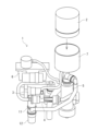
- FIG. 1 is a perspective view of the appearance of a water discharge device to which a liquid supply container according to an embodiment is attached;
- FIG. 2 is an external perspective view showing a part of the inside of the water discharge device.
- 4 is a block diagram showing an example of the configuration of a water channel system and an electrical circuit system of the water discharge device.
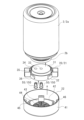
- FIG. FIG. 2 is an exploded perspective view of the liquid supply container.
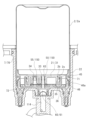
- FIG. 2 is a vertical cross-sectional view of the liquid supply container.
- FIG. 2 is an external perspective view of a supply valve.
- FIG. 2 is a perspective view showing a vertical cross section of a supply valve.
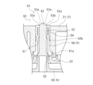
- FIG. FIG. FIG. 4 is an enlarged vertical cross-sectional view of a supply valve portion.
- FIG. 13 is a plan view showing the mouth of the supply valve with the plug inserted therein;
- FIG. 13 is an external perspective view of a supply valve according to a modified example.
- FIG. 13 is an external perspective view of a supply valve according to another modified example.
- FIG. 13 is an external perspective view of a supply valve according to yet another modified example.
- FIG. 13 is an external perspective view of a supply valve according to yet another modified example.
- the water discharge device 1 houses pipes and various parts inside a rectangular parallelepiped case 10.
- a hose 81 extending from a water supply device 80 is connected to a water supply port 11 of the water discharge device 1, and water is supplied from the water supply device 80.
- the water supply device 80 has, for example, a temperature adjustment function, a flow rate adjustment function, and a switching function between passing water and stopping water.
- the water discharge device 1 has a hose 82 of a shower head 83 connected to the water outlet 12.
- the water discharge device 1 discharges either water or bubbles from the water outlet 12, and either water or bubbles is discharged from the shower head 83 to the outside through the hose 82.
- the water discharge device 1 may be connected to a device other than the shower head 83.
- the water discharge device 1 may directly discharge either water or bubbles to the outside.
- the water discharge device 1 may be configured to include discharge components such as the shower head 83.
- the water discharge device 1 may have all of the functions of the water supply device 80.
- the water discharge device 1 may have some of the functions of the water supply device 80.
- the water discharge device 1 is removably connected to a liquid supply container 2 for supplying liquid containing a foaming component.
- An operation button 13 that can be operated by the user and a display 14 that can be seen by the user are arranged on the front of the case 10.
- the display 14 is composed of components such as an LED and an LCD display.
- the size of the case 10 is, for example, approximately 15 cm in height, 20 cm in width, and 5 cm in depth. The size of the case 10 is not limited to this.
- the water discharge device 1 includes a switch 3, a liquid suction device 4, a foaming device 5, a compressor 6, a container mounting section 7, a control circuit section 8, and a power supply section 9.
- a check valve 90 is connected downstream of the water supply port 11, and the check valve 90 and the switch 3 are connected by a flow path 110. The check valve 90 prevents water from flowing back from the flow path 110 to the water supply port 11.
- the switch 3 switches the flow of water to two flow paths 111 and 112 that branch off from the flow path 110.
- One of the flow paths 111 is connected to the junction 92.
- a check valve 91 provided in the flow path 111 prevents backflow from the junction 92 side to the switch 3 side.
- a flow rate regulator 93 and a check valve 94 are provided in the other flow path 112.
- the flow path 112 is connected to the liquid aspirator 4.
- the flow rate regulator 93 is composed of a constant flow rate valve, a pressure reducing valve, etc.
- the flow rate regulator 93 adjusts the flow rate on the downstream side to about 1 liter per minute, for example.
- the check valve 94 prevents backflow from the liquid aspirator 4 side to the switch 3 side.
- the liquid aspirator 4 is, for example, an ejector.
- the liquid aspirator 4 aspirates the liquid supplied from the liquid supply container 2 into the water flowing in from the flow path 112, mixes it, and sends it to the downstream flow path 113.
- the liquid supply container 2 and the liquid aspirator 4 are connected by a flow path 114.
- a check valve 95 is arranged in the flow path 114 to prevent backflow from the liquid aspirator 4 side to the liquid supply container 2 side.
- the flow path 113 is connected to the foamer 5.
- the flow path 113 supplies mixed water, which is a mixture of water and a liquid containing foaming components, to the foamer 5.
- the foamer 5 generates bubbles by mixing the mixed water supplied from the flow path 113 with compressed air from the compressor 6, and sends the bubbles to the flow path 115.
- the compressor 6 sends compressed air to the foamer 5 through the air flow path 116.
- a check valve 96 is arranged in the flow path 116 to prevent backflow from the foamer 5 side to the compressor 6 side.
- the junction 92 is a flow path that joins the flow path 111 and the flow path 115 and connects to the water outlet 12. As described above, the hose 82 of the shower head 83 is connected to the water outlet 12.
- the control circuit unit 8 receives power from the power supply unit 9 and operates the switch 3, compressor 6, etc.
- the power supply unit 9 is, for example, a variety of batteries such as a lithium ion battery.
- the power supply unit 9 may be configured as a power supply circuit for using power supplied from a household power source.
- the control circuit unit 8 accepts operation input from the connected operation button 13 and operates the switch 3, compressor 6, etc.
- the control circuit unit 8 also displays information such as the operating status of the water discharge device 1 and the remaining charge of the power supply unit 9 on the display 14.
- the water discharger 1 discharges water supplied from the water supply device 80 through the flow path 111 from the water outlet 12 without generating bubbles. By switching at the switch 3, the water discharger 1 generates bubbles through the flow paths 112, 113, and 115 and discharges them from the water outlet 12. The water discharger 1 discharges fine bubbles by forming fine bubbles using the foaming device 5.
- the water discharge device 1 switches between a first discharge state in which the supplied water is discharged and a second discharge state in which the supplied water is discharged with a fluid containing an additive.
- the fluid containing an additive in the second discharge state may contain air.
- the water discharge device 1 may cause the supplied water to contain a liquid having a foaming component as the fluid containing an additive in the supplied water in the second discharge state, and may further cause air to be contained to generate foam and discharge the foam from the water discharge port 12.
- the water discharge device 1 may cause the supplied water to contain various additives for washing the user's body, beauty, and health promotion, etc.
- the foamer 5 may be replaced with an ejector and the compressor 6 may be replaced with an air intake mechanism.
- the liquid supply container 2 contains liquid additives to be added to the water supplied to the water discharge device 1.
- the liquid supply container 2 is detachable from the water discharge device 1, and can be replaced with a new one when the liquid inside the container runs out.
- the water discharge device 1 can be used by preparing multiple liquid supply containers 2 filled with liquids with different scents, and by replacing the liquid supply container 2 according to the user's mood before the liquid runs out.
- the water discharge device 1 can be made smaller by attaching and detaching the liquid supply container 2 to supply additives.
- the liquid supply container 2 has a valve 150 consisting of a container body 2a, a lid portion 20, a supply valve 50, and an intake valve 55.
- the container body 2a is a cylindrical hollow container that contains liquid inside.
- the container body 2a has a cylindrical opening 2b.
- the lid portion 20 is attached to the opening 2b.
- the lid portion 20 has an inner lid 21 and an outer lid 22, and is attached so as to cover the opening 2b.
- the inner lid 21 is a flattened cylinder with multiple valve holes 33, 34 penetrating the bottoms 31, 32.
- Valve hole 33 is located in the center, and valve hole 34 is located in an eccentric position.
- a supply valve 50 is attached to the valve hole 33.
- An intake valve 55 is attached to the valve hole 34.
- the inner lid 21 has side walls 35, 36.
- the side wall 35 is cylindrical, and a bottom 31 is formed at the end on the container body 2a side.
- the side wall 35 fits into the inside of the opening 2b of the container body 2a.
- the side wall 36 has a larger diameter than the side wall 35, and fits into the outside of the opening 2b of the container body 2a.
- the outer lid 22 is a flattened cylinder and is attached to cover the inner lid 21.
- the side wall 41 of the outer lid 22 is fitted to the inner surface of the container attachment part 7 provided on the water discharge device 1 side.
- the bottom 42 of the outer lid 22 has valve holes 43, 44 that penetrate the bottom 42 at positions corresponding to the valve holes 33, 34 of the inner lid 21.
- the bottom 42 has claw parts 45 that are hooked onto the side wall 36 of the inner lid 21 at each of four equal positions in the circumferential direction.
- the outer lid 22 has an attachment part 46 formed by drilling the side wall 41.
- the side wall 35 of the inner lid 21 fits tightly against the inside of the opening 2b of the container body 2a.
- the side wall 36 of the inner lid 21 is prevented from coming off by fitting into an annular protrusion 2c provided on the outside of the opening 2b of the container body 2a.
- the claw 45 of the outer lid 22 is hooked onto the side wall 36 of the inner lid 21.
- the mounting portion 46 of the outer lid 22 has a protrusion 46a.
- a claw 71 formed on the inside of the side wall 70 of the container mounting portion 7 is hooked onto the protrusion 46a.
- the container attachment section 7 has a plug section 60 provided at the bottom 72.
- the plug 63 of the plug section 60 extends towards the liquid supply container 2 and is inserted into the supply valve 50.
- the supply valve 50 is opened when the plug 63 is inserted.
- the supply valve 50 is opened, the liquid contained in the liquid supply container 2 flows through the plug 63 into the flow path 114.
- the supply valve 50 and the intake valve 55 are held in place by being sandwiched between the inner lid 21 and the outer lid 22.
- the supply valve 50 and intake valve 55 constituting the valve 150 are made of an elastic material such as rubber and have the same structure.
- the supply valve 50 and intake valve 55 are duckbill valves or the like.
- the supply valve 50 will be described below as an example.
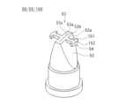
- the supply valve 50 has a sealing portion 51, a base portion 52, a mouth portion 53 and a rib portion 54, and is formed into a cylindrical shape as a whole.
- the sealing portion 51 is cylindrical, and has a flange portion 51a that extends outward from one end. The other end of the sealing portion 51 is continuous with the base portion 52.
- the sealing portion 51 is provided on the outer side of the mouth portion 53 when viewed from the container body 2a side.
- the root portion 52 is hollow and tubular, extending like a spatula with a mouth portion 53 formed at one bottom portion 52a.
- the other bottom portion 52b of the root portion 52 is connected to the other end side of the sealing portion 51.
- the root portion 52 widens from the one bottom portion 52a to the other bottom portion 52b.
- a linear cut 53a is provided in the mouth portion 53.
- the mouth portion 53 is closed when the peripheral portions 53b, 53c on both sides of the cut 53a are in close contact with each other.
- the mouth portion 53 is in a closed state when no load is applied and in a free state.
- the mouth 53 opens as a result of the peripheral portions 53b, 53c elastically deforming in a direction receding from the slit 53a.
- the direction in which the peripheral portions 53b, 53c deform when the mouth 53 opens is perpendicular to the extension direction of the slit 53a and the central axis direction of the supply valve 50.
- the central axis direction of the supply valve 50 is the same as the insertion direction of the plug 63 on the container attachment portion 7 side relative to the supply valve 50.
- the mouth 53 opens as a result of the peripheral portions 53b, 53c elastically deforming in a direction intersecting the insertion direction of the plug 63 inserted into the supply valve 50.
- the root portion 52 has a first wall portion 52d and a second wall portion 52e that extend from one bottom portion 52a to the other bottom portion 52b.
- the first wall portion 52d and the second wall portion 52e are inclined with respect to the axial direction of the root portion 52 so that the distance between them increases from the one bottom portion 52a to the other bottom portion 52b.
- the flow path S1 formed inside the root portion 52 increases in width from the one bottom portion 52a to the other bottom portion 52b.
- the flow path S1 is continuous with the cut 53a.
- the rib portion 54 is provided on the outer surface 52c of the root portion 52, and is formed so as to protrude in a direction intersecting the axial direction of the notch 53a and the root portion 52.
- One end 54a of the rib portion 54 is connected to one bottom 52a of the root portion 52, and extends from the one end 54a in a direction intersecting the axial direction of the notch 53a and the root portion 52, then bends and extends in the axial direction of the root portion 52.
- the other end 54b of the rib portion 54 is connected to a position closer to the other bottom 52b of the root portion 52.
- the rib portion 54 is provided so as to extend from one bottom portion 52a of the root portion 52 to the other bottom portion 52b.
- the rib portion 54 is provided on both the first wall portion 52d and the second wall portion 52e.
- the outer edge portion 54c of the rib portion 54 contacts the inner surface of the valve hole 33 into which the root portion 52 is inserted.
- the plug 60 has a plug body 61, a body 62, and a plug 63.
- the plug body 61 is cylindrical, and has a flow path formed therein for liquid to flow through.
- the body 62 is cylindrical, and extends from the plug body 61 toward the liquid supply container 2.
- the inside of the body 62 is connected to the inside of the plug body 61.
- the plug 63 is rod-shaped, and extends from the end 62a of the body 62 toward the liquid supply container 2, and is supported by the body 62. In a cross section intersecting the central axis direction, the plug 63 has a perforated outer surface, leaving plate-shaped members on two perpendicular diameters.
- a number of through holes 62b are formed between the end 62a of the body 62 and the stopper 63.
- the through holes 62b communicate with the interior of the body 62 and the interior of the stopper body 61.
- the liquid supplied from the liquid supply container 2 flows through the multiple through holes 62b, the interior of the body 62, and the interior of the stopper body 61 to the flow path 114.
- the liquid supply container 2 Before attaching the liquid supply container 2 to the water discharge device 1, the liquid supply container 2 can be carried in any position. For example, the user may hold the liquid supply container 2 with the lid portion 20 facing up, or may hold it upside down.
- the supply valve 50 of the liquid supply container 2 is in a free state and closed.
- the intake valve 55 is also in a free state and closed.
- the liquid in the container body 2a acts as weight on the supply valve 50 and the intake valve 55, applying a load to them.
- the load applied by the liquid acts in a direction that brings the peripheral portions 53b, 53c of the mouth portions 53 of the supply valve 50 and the intake valve 55 into close contact with each other, so that the closed state is maintained.
- the rib portions 54 of the supply valve 50 and the intake valve 55 help to bring the peripheral portions 53b, 53c of the mouth portions 53 into close contact with each other.
- the plug 63 With the liquid supply container 2 attached to the water discharge device 1, the plug 63 is inserted into the supply valve 50.
- the mouth 53 of the supply valve 50 is opened by the insertion of the plug 63.
- the peripheral edges 53b, 53c of the mouth 53 elastically deform in a direction intersecting the insertion direction of the plug 63, and the slit 53a opens.
- the rib 54 elastically deforms under compression so as to be pressed between the peripheral edges 53b, 53c of the mouth 53 and the inner surface of the valve hole 33. As shown in Figure 11, a gap D is created between the mouth 53 and the plug 63.
- the liquid in the container body 2a flows out from the gap D and is supplied to the water discharge device 1 through the through hole 62b of the plug portion 60.
- the liquid supply container 2 is closed and open by inserting and removing the plug 63 into the supply valve 50, which is advantageous in simplifying the structure of the valve portion and reducing costs.
- the sealing portion 51 of the supply valve 50 is fitted with the body portion 62 that supports the plug 63, and comes into contact with the body portion 62 in a tight fit to prevent liquid leakage.
- the supply valve 50 is made of an elastic material such as rubber, and can be tightly fitted to the body portion 62.
- the sealing portion 51 is prevented from shifting position by maintaining the position of the supply valve 50, and the function of preventing liquid leakage can be maintained.
- the supply valve 50 is held in place by sandwiching the flange 51a between the inner lid 21 and the outer lid 22.
- the supply valve 50 can be held in place by the inner lid 21 and the outer lid 22 in a simple configuration.
- the intake valve 55 can be configured in the same way as the supply valve 50. As described above, when the lid 20 of the liquid supply container 2 is on the lower side, the intake valve 55 is closed. When the liquid in the container body 2a is supplied to the water discharge device 1 and the pressure in the container body 2a drops, air is sucked in through the intake valve 55. The intake valve 55 opens at the moment the air is sucked in. At the moment the intake valve 55 opens, the sucked in air holds the liquid in the container body 2a, preventing liquid leakage.
- the intake valve 55 is held in place by sandwiching the flange 51a between the inner lid 21 and the outer lid 22.
- the intake valve 55 can be held in place by the inner lid 21 and the outer lid 22 in a simple configuration.
- the plug 63 is pulled out from the supply valve 50.
- the rib portion 54 of the supply valve 50 elastically deforms to return to its original state due to a restoring force, and exerts a force on the peripheral portions 53b, 53c of the mouth portion 53 in a direction in which the slit 53a closes.
- the supply valve 50 is able to increase the restoring force that closes the slit 53a, thereby suppressing the outflow of liquid.
- the supply valve 50 has a rib portion 54 that extends from one bottom portion 52a of the base portion 52 to the other bottom portion 52b, so that the rib portion 54 can reliably contact the inner surface of the valve hole 33 and exert a restoring force.
- the supply valve 50 can apply a force to close the slit 53a at a location close to the peripheral edges 53b, 53c of the slit 53a of the mouth 53 by connecting one end 54a of the rib 54 to one bottom 52a of the root 52.
- the supply valve 50 can apply a restoring force to close the slit 53a of the mouth 53 from a position on the side of the other bottom 52b of the root 52 by connecting the other end 54b of the rib 54 to a position closer to the other bottom 52b of the root 52.
- the supply valve 50 When the rib portion 54 comes into contact with the inner surface of the valve hole 33, the supply valve 50 is elastically deformed so as to be pressed between the peripheral portions 53b and 53c of the mouth portion 53 and the inner surface of the valve hole 33, and a restoring force can be applied to the mouth portion 53.
- the supply valve 50 may have the rib portion 54 in contact with the inner surface of the valve hole 33.
- the supply valve 50 may have a gap between the rib portion 54 and the inner surface of the valve hole 33.
- the supply valve 50 may be configured to elastically deform so that when the plug 63 is inserted, the gap between the rib portion 54 and the inner surface of the valve hole 33 is filled and the rib portion 54 is pressed between the peripheral portions 53b and 53c and the inner surface of the valve hole 33.
- the supply valve 50 functions so that when the plug 63 is inserted, the liquid in the space S2 inside the container body 2a flows into the flow path S1, and when the plug 63 is removed, the supply valve 50 prevents the liquid from leaking into the flow path S1.
- the supply valve 50 may be used in a circuit configuration in which the flow path S1 side is the primary side and the space S2 side is the secondary side, and liquid flows from the primary side to the secondary side.
- the supply valve 50 functions such that as the pressure of the liquid on the primary side (flow path S1 side) increases, the slit 53a of the mouth 53 opens, allowing the liquid to flow to the secondary side (space S2 side). As the pressure of the liquid on the primary side decreases and approaches the pressure on the secondary side, the slit 53a of the mouth 53 closes, stopping the flow of liquid to the secondary side, and suppressing the outflow of liquid from the secondary side to the primary side.
- a valve 150 formed by the supply valve 50 and the intake valve 55 according to the modified example has a rib portion 54 that projects from one bottom 52a of the root portion 52 in a direction intersecting the axial direction of the slit 53a and the root portion 52.
- the rib portion 54 has a rod-shaped base portion 151 that extends from one bottom 52a of the root portion 52 in a direction intersecting the axial direction of the slit 53a and the root portion 52, and an arc-shaped outer edge portion 152 provided at the tip of the base portion 151.
- the outer edge portion 152 of the rib portion 54 contacts the inner surface of the valve hole 33.
- the rib portion 54 comes into contact with the inner surface of the valve hole 33, and is pushed between the peripheral edges 53b and 53c of the mouth portion 53 and the inner surface of the valve hole 33, causing elastic deformation, and a restoring force can be applied to the mouth portion 53.
- a valve 150 according to another modified example has a plate-shaped rib portion 54 that extends from one bottom portion 52a to the other bottom portion 52b of the root portion 52.
- the rib portion 54 protrudes in a direction that intersects with the axial direction of the cut 53a and the root portion 52.
- the outer edge portion 54c of the rib portion 54 contacts the inner surface of the valve hole 33.
- a valve 150 according to yet another modification has a rib portion 54 that extends from one bottom 52a to the other bottom 52b of the root portion 52 in a direction intersecting the axial direction of the notch 53a and the root portion 52.
- the rib portion 54 has a base portion 151 that extends in a direction intersecting the axial direction of the notch 53a and the root portion 52 and is bent midway, and an arc-shaped outer edge portion 152 provided at the tip of the base portion 151.
- the outer edge portion 152 of the rib portion 54 is formed from one bottom portion 52a to the other bottom portion 52b of the root portion 52.
- the rib portion 54 contacts the inner side of the valve hole 33.
- the outer edge portion 152 of the rib portion 54 contacts the inner side of the valve hole 33.
- a valve 150 according to yet another modified example has a rib portion 54 that extends from one bottom 52a of the root portion 52 in a direction intersecting the slit 53a and the axial direction of the root portion 52.
- the rib portion 54 has two rod-shaped base portions 151 that extend from one bottom 52a of the root portion 52 in a direction intersecting the slit 53a and the axial direction of the root portion 52.
- the two base portions 151 are spaced apart in the direction in which the slit 53a extends.
- the tip of the base portion 151 of the rib portion 54 contacts the inner surface of the valve hole 33.
- the valve 150 which is composed of the supply valve 50 and the intake valve 55, is not limited to being cylindrical, but may be a polygonal square tube.
- the container body 2a, the inner lid 21 and the outer lid 22 of the lid portion 20 are not limited to being cylindrical, but may be a polygonal square tube.
- the supply valve 50 and the intake valve 55 may be held by either the inner lid 21 or the outer lid 22.
- the shape of the plug 63 provided in the container attachment portion 7 of the water discharge device 1 is not limited to the above example.
- the plug 63 can be of any shape that creates a gap D between the plug 63 and the mouth portion 53 of the supply valve 50 when inserted into the supply valve 50.
- the first item is a valve that includes a mouth portion having a slit, a cylindrical base portion that forms a flow path that is continuous with the slit and in which the flow path widens as it moves from one bottom portion where the mouth portion is formed to the other bottom portion, and a rib portion that is provided on the outer surface of the base portion and extends in a direction that intersects with the slit.
- the second item is the valve described in the first item, in which the rib portion is arranged to extend from the one bottom portion to the other bottom portion.
- the third item is a valve according to any one of the first and second items, in which the rib portion is formed so that one end is connected to the one bottom portion, the rib portion extends from the one end in a direction intersecting the cut, bends and extends in the axial direction of the root portion, and the other end is connected to the root portion.
- the fourth item is a valve according to any one of the first to third items, in which the base portion is inserted into an external valve hole and the rib portion contacts the inner surface of the valve hole.
- the fifth item is a liquid supply container that includes a valve as described in any one of the first to third items, a container body that contains the liquid to be supplied to the water discharge device, and a lid that covers the opening of the container body and has a valve hole through which the valve is inserted.
- the sixth item is the liquid supply container described in the fifth item, in which the rib contacts the inner surface of the valve hole.
- This disclosure relates to a valve and a liquid refill container and can be used with the valve and the liquid refill container.
Landscapes
- Engineering & Computer Science (AREA)
- General Engineering & Computer Science (AREA)
- Mechanical Engineering (AREA)
- Closures For Containers (AREA)
- Containers And Packaging Bodies Having A Special Means To Remove Contents (AREA)
Abstract
バルブ150は、口部53、付根部52およびリブ部54を備える。口部53は、切目53aを有する。付根部52は、切目53aに連続する流路を形成し、口部53が形成された一底部52aから他底部52bへ向かうにつれて流路が広がる筒状に形成されている。リブ部54は、付根部52の外側面に設けられ、切目53aに交差する方向へ張り出す。
Description
本開示は、バルブおよび液体補給容器に関する。
特許文献1は、従来のダックビル弁を開示している。このダックビル弁は、第1流路を有する第1流路形成部と、第1壁部と第2壁部との間に、第1流路形成部に近付くに従って広くなった第2流路を有する第2流路形成部と、を有し、第2流路形成部は、先端部にスリットが形成されており、スリットが開くことで第2流路が下流側流路と連通し、スリットが閉じることで第2流路と下流側流路との連通が遮断される。第1流路形成部の内径寸法を第1流路形成部の外径寸法で除した比の値は、0.65未満であり、かつ、第1壁部と第2壁部とがなす交差角は、50度以上65度以下の範囲にある。下流側流路の圧力に対する第2流路の圧力差が-75kPaの負圧である場合、第1壁部及び第2壁部は、接触しない。
本願発明者は、吐水装置に液体を補給する容器のバルブについて検討し、次の新たな認識を得た。特許文献1に記載のダックビル弁は、1次側から2次側への流れを許容し、逆方向への流れを防ぐ機能を有している。しかし、ダックビル弁などのバルブにおいて、例えば1次側から2次側へ液体を流し続けた後に、1次側と2次側の圧力が同程度になった場合、バルブが閉じきらず2次側から1次側へ液体が流出してしまうという問題点があった。
本開示の目的は、液体の流出を抑制することができるバルブおよび液体補給容器を提供することにある。
前述の課題を解決するために、本開示のある態様はバルブである。ある態様のバルブは、切目を有する口部と、前記切目に連続する流路を形成し、前記口部が形成された一底部から他底部へ向かうにつれて前記流路が広がる筒状の付根部と、前記付根部の外側面に設けられ、前記切目に交差する方向へ張り出すリブ部と、を備える。
本開示のある態様は液体補給容器である。ある態様の液体補給容器は、上述のバルブと、吐水装置に補給する液体を収容する容器本体と、前記容器本体の開口部を覆い、前記バルブが挿入されるバルブ孔が形成された蓋部と、を備える。
以下、本開示の吐水装置を実施するための実施形態を説明する。同一の構成要素には同一の符号を付し、重複する説明を省略する。各図面では、説明の便宜のため、適宜、構成要素を省略、拡大、縮小する。図面は符号の向きに合わせて見るものとする。本明細書で言及する構造及び形状に言及している内容に厳密に一致する構造及び形状のみでなく、寸法誤差、製造誤差等の誤差の分だけずれた構造及び形状も含む。各図面において実施形態を説明する上で重要ではない部材の一部は省略して表示する。
第1、第2などの序数を含む用語は多様な構成要素を説明するために用いられる。この用語は一つの構成要素を他の構成要素から区別する目的でのみ用いられ、この用語によって本開示の構成が限定されるものではない。以下の実施形態は、本開示の内容理解を助けるために例示するものであり、本開示の構成を限定するものではない。
[実施形態]
図1を参照する。吐水装置1は、直方体状のケース10の内部に、配管や各種の部品を収容している。吐水装置1は、給水装置80から延びるホース81が給水口11に接続され、給水装置80から水が供給される。給水装置80は、例えば、温度調節機能、流量調節機能、並びに通水および止水の切替機能を有している。
図1を参照する。吐水装置1は、直方体状のケース10の内部に、配管や各種の部品を収容している。吐水装置1は、給水装置80から延びるホース81が給水口11に接続され、給水装置80から水が供給される。給水装置80は、例えば、温度調節機能、流量調節機能、並びに通水および止水の切替機能を有している。
吐水装置1は、吐水口12にシャワーヘッド83のホース82が接続されている。吐水装置1は吐水口12から水および泡のいずれか一方を吐水し、ホース82を通してシャワーヘッド83から水および泡のいずれか一方が外部へ吐出される。吐水装置1は、シャワーヘッド83以外の装置に接続されてもよい。吐水装置1は、直接的に外部へ水および泡のいずれか一方を吐出してもよい。吐水装置1は、シャワーヘッド83等の吐出用の部品を含む構成であってもよい。吐水装置1は、給水装置80の機能の全部を有してもよい。吐水装置1は、給水装置80の機能の一部を有してもよい。
吐水装置1は、泡立ち成分を含有した液体を補給するための液体補給容器2が着脱可能に接続される。ケース10の前面には、ユーザが操作可能な操作ボタン13、ユーザが視認可能な表示器14が配置されている。表示器14は、LED、液晶ディスプレイ等の部品で構成される。ケース10の大きさは、例えば高さ15cm、横幅20cm、奥行き5cm程度である。ケース10の大きさはこれに限られない。
図2、図3を参照する。吐水装置1は、切替器3、液体吸引器4、発泡器5、コンプレッサー6、容器装着部7、制御回路部8および電源部9等を有する。給水口11の下流には逆止弁90が接続され、逆止弁90と切替器3とが流路110により接続される。逆止弁90は、流路110から給水口11側への水の逆流を阻止する。
切替器3は、流路110から分岐する2方向の流路111および112へ通水を切り替える。一方の流路111は、合流部92に接続される。流路111に設けられた逆止弁91は、合流部92側から切替器3側への逆流を阻止する。他方の流路112には、流量規制器93および逆止弁94が配置されている。流路112は、液体吸引器4に接続される。流量規制器93は、定流量弁、減圧弁などで構成されている。流量規制器93は、例えば下流側の流量が毎分1リットル程度となるように調節する。逆止弁94は、液体吸引器4側から切替器3側への逆流を防止する。
液体吸引器4は、例えばエゼクターである。液体吸引器4は、流路112から流れ込む水に、液体補給容器2から補給された液体を吸引して混合させ、下流側の流路113へ流す。液体補給容器2および液体吸引器4は流路114で接続されている。流路114には、液体吸引器4側から液体補給容器2側への逆流を防止する逆止弁95が配置されている。
流路113は、発泡器5に接続される。流路113は、泡立ち成分を含有した液体と水とが混合した混合水を発泡器5に供給する。発泡器5は、流路113から供給された混合水に、コンプレッサー6からの圧縮空気を混ぜることで泡を生成し、流路115へ流す。コンプレッサー6は空気の流路116を通して発泡器5へ圧縮空気を送り込む。流路116には、発泡器5側からコンプレッサー6側への逆流を防止する逆止弁96が配置されている。
合流部92は、流路111と流路115とを合流させ、吐水口12へ接続する流路である。上述のように、吐水口12には、シャワーヘッド83のホース82が接続される。
制御回路部8は、電源部9からの電力供給を受け、切替器3およびコンプレッサー6等を動作させる。電源部9は、例えばリチウムイオン電池等の種々の電池である。電源部9は、家庭用電源から供給される電力を用いるための電源用回路で構成されていてもよい。制御回路部8は、接続される操作ボタン13からの操作入力を受け付けて、切替器3およびコンプレッサー6等を動作させる。また制御回路部8は、吐水装置1の動作状態、電源部9の残量等の情報を表示器14に表示させる。
吐水装置1は、流路111を介して、給水装置80から供給される水を泡生成することなく吐水口12から吐出する。吐水装置1は、切替器3での切替によって、流路112、113および115を介して泡を生成し、吐水口12から吐出する。吐水装置1は、発泡器5によって微細な気泡が形成され、きめ細かな泡を吐出する。
吐水装置1は、供給された水を吐出する第1吐出状態と、供給された水に添加剤を含ませた流体を吐出する第2吐出状態とを切り替える。第2吐出状態における添加剤を含ませた流体は、空気を含んでいてもよい。吐水装置1は、第2吐出状態における供給された水に添加剤を含ませた流体として、泡立ち成分を有する液体を供給された水に含ませ、更に空気を含ませて発泡させた泡を生成し、吐水口12から吐出してもよい。吐水装置1は、ユーザの身体の洗浄、美容および健康増進等のために種々の添加剤を供給された水に含ませるようにしてもよい。吐水装置1は、泡立ち成分を有する液体以外の添加剤を供給された水に含ませる場合には、発泡器5をエゼクターに代替し、コンプレッサー6を吸気機構に代替してもよい。
液体補給容器2は、吐水装置1に供給された水に含ませる液体の添加剤を収容している。液体補給容器2は、吐水装置1に着脱可能であり、容器内の液体が無くなると新しいものに交換できる。吐水装置1は、例えば香りの異なる液体を詰めた複数の液体補給容器2を用意しておき、液体が無くなる前に、ユーザが気分に合わせて液体補給容器2を交換して使用することができる。吐水装置1は、液体補給容器2を着脱して添加剤を供給することによって、吐水装置1を小型化することができる。
図4を参照する。液体補給容器2は、容器本体2a、蓋部20、供給バルブ50および吸気バルブ55で構成されるバルブ150を有する。容器本体2aは、円筒状の中空の容器であり、内部に液体を収容する。容器本体2aは、円筒状の開口部2bを有する。開口部2bには、蓋部20が取り付けられる。蓋部20は、内蓋21および外蓋22を有し、開口部2bを覆うように取り付けられる。
内蓋21は、偏平の円筒状であり、底部31および底部32を貫通する複数のバルブ孔33、34を有する。バルブ孔33は中央に設けられており、バルブ孔34は偏心した位置に設けられている。バルブ孔33には、供給バルブ50が取り付けられる。バルブ孔34には、吸気バルブ55が取り付けられる。
内蓋21は、側壁部35、36を有する。側壁部35は、円筒状であり、容器本体2a側の端部に底部31が形成される。側壁部35は、容器本体2aの開口部2bの内側に嵌め合わされる。側壁部36は、側壁部35よりも直径が大きく、容器本体2aの開口部2bの外側に嵌め合わされる。
外蓋22は、偏平の円筒状であり、内蓋21を覆うように取り付けられる。外蓋22の側壁部41は、吐水装置1側に設けられる容器装着部7の内側面に嵌め合わされる。外蓋22の底部42は、内蓋21のバルブ孔33、34に対応する位置に底部42を貫通するバルブ孔43、44を有する。底部42は、内蓋21の側壁部36に掛け止められる爪部45を周方向に4等分した各位置に有する。外蓋22は、側壁部41を穿つようにして形成される装着部46を有する。
図5を参照する。内蓋21の側壁部35は、容器本体2aの開口部2bの内側に密着するように嵌め合わされている。内蓋21の側壁部36は、容器本体2aの開口部2bの外側に設けられた環状突起部2cに嵌め合わされることによって、抜け止めされている。外蓋22の爪部45は、内蓋21の側壁部36に掛け止められる。外蓋22の装着部46は、突起部46aを有している。突起部46aには、容器装着部7の側壁部70の内側に形成された爪部71が掛け止められる。
容器装着部7は、底部72に栓部60が設けられている。栓部60の栓63は、液体補給容器2側へ延び、供給バルブ50に挿入される。供給バルブ50は、栓63が挿入されることによって開状態となる。供給バルブ50が開状態になることによって、液体補給容器2に収容された液体が栓63を通って流路114に流れ込む。
供給バルブ50および吸気バルブ55は、内蓋21と外蓋22との間に挟み込むようにして保持されている。
図6を参照する。バルブ150を構成する供給バルブ50および吸気バルブ55は、ゴム等の弾性材料によって形成されており、同等の構造を有している。供給バルブ50および吸気バルブ55は、ダックビル弁などである。以下、供給バルブ50を例に説明する。供給バルブ50は、封止部51、付根部52、口部53およびリブ部54を有し、全体として筒状に形成されている。封止部51は、円筒状であり、一端側に外側へ延びる鍔部51aを有する。封止部51の他端側は、付根部52に連続している。封止部51は、容器本体2aの側から見て口部53の外部側に設けられている。
付根部52は、中空の筒状であり、ヘラ状に延びて一底部52aに口部53が形成されている。付根部52の他底部52bは、封止部51の他端側に接続されている。付根部52は、一底部52aから他底部52bへ向かうにつれて拡幅している。口部53には直線状の切目53aが設けられている。口部53は、切目53aの両側における周縁部53b、53cが密着することによって、閉状態となる。口部53は、荷重がかかっていない自由状態において、閉状態となっている。
口部53は、周縁部53b、53cが切目53aから後退する方向へ弾性的に変形することによって開状態となる。口部53が開状態となる際に周縁部53b、53cが変形する方向は、切目53aの延びる方向および供給バルブ50の中心軸方向に直交する方向である。供給バルブ50の中心軸方向は、供給バルブ50に対する容器装着部7側の栓63の挿入方向と同じである。口部53は、供給バルブ50に挿入される栓63の挿入方向に交差する方向へ周縁部53b、53cが弾性変形することによって開状態となる。
図7を参照する。付根部52は、一底部52aから他底部52bへ延びる第1壁部52dおよび第2壁部52eを有している。第1壁部52dおよび第2壁部52eは、互いの間隔が一底部52aから他底部52bへ向かうにつれて広がるように、付根部52の軸方向に対して傾斜している。付根部52の内部に形成される流路S1は、一底部52aから他底部52bへ向かうにつれて広がっている。流路S1は切目53aに連続している。
リブ部54は、付根部52の外側面52cに設けられ、切目53aおよび付根部52の軸方向に交差する方向へ張り出すように形成されている。リブ部54は、一端部54aが付根部52の一底部52aに接続され、一端部54aから切目53aおよび付根部52の軸方向に交差する方向へ延び、屈曲して付根部52の軸方向に延びる。リブ部54の他端部54bは、付根部52の他底部52b寄りの位置に接続されている。
リブ部54は、付根部52の一底部52aから他底部52bへ向かって延びるように設けられている。リブ部54は、第1壁部52dおよび第2壁部52eの両方に設けられている。リブ部54の外縁部54cは、付根部52が挿入されるバルブ孔33の内側面に接触する。
図8、図9を参照する。栓部60は、栓本体部61、胴部62および栓63を有する。栓本体部61は、円筒状であり、内部に液体を通流する流路が形成される。胴部62は、円筒状であり、栓本体部61から液体補給容器2側へ延びる。胴部62の内部は、栓本体部61の内部に通じている。栓63は、棒状であり、胴部62の端部62aから液体補給容器2側へ延びており、胴部62によって支持されている。栓63は、中心軸方向に交差する断面において、直交する2つの直径上に板状部材を残して、外側面を穿った形状となっている。
胴部62の端部62aには、栓63との間に複数の貫通孔62bが形成されている。貫通孔62bは、胴部62の内部、および栓本体部61の内部に通じている。液体補給容器2から供給される液体は、複数の貫通孔62b、胴部62の内部、および栓本体部61の内部を通って流路114へ流れる。
次に液体補給容器2を吐水装置1へ装着する際の動作について説明する。液体補給容器2を吐水装置1へ装着する前の段階では、液体補給容器2は任意の姿勢で持ち運ばれる。ユーザは、例えば液体補給容器2の蓋部20を上側にして容器を持つこともあるし、逆さにして持つこともある。液体補給容器2の供給バルブ50は、栓63が挿入されていない状態では、自由状態となっており、閉状態となっている。吸気バルブ55も自由状態であり、閉状態となっている。
液体補給容器2の蓋部20が下側になる場合、容器本体2a内の液体が供給バルブ50および吸気バルブ55に重みとなって荷重が加わる。液体によって加わる荷重は、供給バルブ50および吸気バルブ55の口部53の周縁部53b、53cを互いに密着させる方向に働くので、閉状態が維持される。供給バルブ50および吸気バルブ55のリブ部54は、口部53の周縁部53b、53cが互いに密着するように補助する。
図10、図11を参照する。液体補給容器2を吐水装置1へ装着した状態において、栓63は、供給バルブ50に挿入される。供給バルブ50の口部53は、栓63の挿入によって開状態になる。口部53の周縁部53b、53cは、栓63の挿入方向に交差する方向へ弾性変形し、切目53aが開く。リブ部54は、口部53の周縁部53bおよび53cと、バルブ孔33の内側面との間に押し込まれるように圧縮力を受けて弾性変形する。図11に示すように、口部53と栓63との間に隙間Dが生じる。
容器本体2a内の液体は、隙間Dから流れ出し、栓部60の貫通孔62bを通って吐水装置1へ供給される。液体補給容器2は、供給バルブ50に栓63を抜き差しする構造によって閉状態、開状態となるため、バルブ部分の構成の簡潔化に有利であり、低コスト化を図れる。
供給バルブ50の封止部51は、栓63を支持する胴部62が嵌め合わされ、胴部62と接触して密着することによって液漏れを防止する。供給バルブ50は、上述のようにゴム等の弾性材料で形成されており、胴部62と密着させることができる。封止部51は、供給バルブ50の位置が保持されていることによって位置ずれが抑制され、液漏れ防止機能を維持することができる。
供給バルブ50は、内蓋21および外蓋22との間に鍔部51aが挟み込まれるようにして保持されている。供給バルブ50は、内蓋21および外蓋22によって簡潔な構成によって保持することができる。
吸気バルブ55は、供給バルブ50と同様に構成することができる。上述のように、液体補給容器2の蓋部20が下側になる場合、吸気バルブ55は閉状態となる。容器本体2a内の液体が吐水装置1へ供給され、容器本体2a内の圧力が低下すると、吸気バルブ55から空気が吸い込まれる。吸気バルブ55は、空気が吸い込まれる瞬間に開状態となる。吸気バルブ55は、開状態となる瞬間において、吸い込まれる空気によって液体を容器本体2a内に押し留めており、液漏れを抑制できる。
吸気バルブ55は、供給バルブ50と同様に、内蓋21および外蓋22との間に鍔部51aが挟み込まれるようにして保持されている。吸気バルブ55は、内蓋21および外蓋22によって簡潔な構成によって保持することができる。
液体補給容器2が吐水装置1から取り外される際、供給バルブ50から栓63が引き抜かれる。供給バルブ50のリブ部54は、復元力によって元の状態に戻るように弾性変形し、口部53の周縁部53b、53cに対して、切目53aが閉じる方向に力を及ぼす。供給バルブ50は、リブ部54を設けることによって、切目53aを閉じる復元力が高められ、液体の流出を抑制することができる。
供給バルブ50は、リブ部54が付根部52の一底部52aから他底部52bに向かって延びるように設けられていることによって、バルブ孔33の内側面に確実に接触しリブ部54の復元力を発揮させることができる。
供給バルブ50は、リブ部54の一端部54aが付根部52の一底部52aに接続されることによって、口部53の切目53aの周縁部53b、53cに近い箇所で切目53aを閉じさせる力を作用させることができる。供給バルブ50は、リブ部54の他端部54bが付根部52の他底部52b寄りの位置に接続されることによって、付根部52の他底部52b側の位置から口部53の切目53aを閉じる復元力を作用させることができる。
供給バルブ50は、リブ部54がバルブ孔33の内側面に接触することによって、口部53の周縁部53bおよび53cと、バルブ孔33の内側面との間に押し込まれるように弾性変形し、復元力を口部53に作用させることができる。
供給バルブ50は、栓63が挿入されていない状態において、リブ部54がバルブ孔33の内側面に接触していてもよい。供給バルブ50は、栓63が挿入されていない状態において、リブ部54とバルブ孔33の内側面との間に隙間があってもよい。供給バルブ50は、栓63が挿入された状態において、リブ部54とバルブ孔33の内側面との間の隙間が埋まり、リブ部54が周縁部53bおよび53cと、バルブ孔33の内側面との間に押し込まれるように弾性変形するように構成するとよい。
供給バルブ50は、栓63を挿入することによって、容器本体2a内の空間S2にある液体が流路S1へ流れ、栓63が引き抜かれることによって、液体が流路S1へ漏れることを抑制するように機能する。
供給バルブ50は、流路S1側を1次側とし、空間S2側を2次側として、1次側から2次側へ液体を流すような回路構成に使用してもよい。供給バルブ50は、1次側(流路S1側)の液体の圧力が高まることで口部53の切目53aが開いて、2次側(空間S2側)へ液体が流れるように機能する。供給バルブ50は、1次側の液体の圧力が低下して2次側の圧力に近づくことにより、口部53の切目53aが閉じて2次側への液体の流れが停止し、2次側から1次側への液体の流出を抑制することができる。
[変形例]
図12を参照する。変形例に係る供給バルブ50および吸気バルブ55で構成されるバルブ150は、付根部52の一底部52aから切目53aおよび付根部52の軸方向に交差する方向へ張り出すリブ部54を有する。リブ部54は、付根部52の一底部52aから切目53aおよび付根部52の軸方向に交差する方向へ延びる棒状の基部151、および基部151の先端に設けられる円弧状の外縁部152を有する。リブ部54の外縁部152は、バルブ孔33の内側面に接触する。
図12を参照する。変形例に係る供給バルブ50および吸気バルブ55で構成されるバルブ150は、付根部52の一底部52aから切目53aおよび付根部52の軸方向に交差する方向へ張り出すリブ部54を有する。リブ部54は、付根部52の一底部52aから切目53aおよび付根部52の軸方向に交差する方向へ延びる棒状の基部151、および基部151の先端に設けられる円弧状の外縁部152を有する。リブ部54の外縁部152は、バルブ孔33の内側面に接触する。
変形例に係るバルブ150は、リブ部54がバルブ孔33の内側面に接触することによって、口部53の周縁部53bおよび53cとバルブ孔33の内側面との間にリブ部54が押し込まれて弾性変形し、復元力を口部53に作用させることができる。
図13を参照する。別の変形例に係るバルブ150は、付根部52の一底部52aから他底部52bにかけて延びる板状のリブ部54を有する。リブ部54は、切目53aおよび付根部52の軸方向に交差する方向へ張り出している。リブ部54の外縁部54cは、バルブ孔33の内側面に接触する。
バルブ150は、リブ部54がバルブ孔33の内側面に接触することによって、口部53の周縁部53bおよび53cとバルブ孔33の内側面との間にリブ部54が押し込まれて弾性変形し、復元力を口部53に作用させることができる。
図14を参照する。更に別の変形例に係るバルブ150は、付根部52の一底部52aから他底部52bにかけて、切目53aおよび付根部52の軸方向に交差する方向へ張り出すリブ部54を有する。リブ部54は、切目53aおよび付根部52の軸方向に交差する方向へ延び、途中において屈曲させた基部151、および基部151の先端に設けられる円弧状の外縁部152を有する。リブ部54の外縁部152は、付根部52の一底部52aから他底部52bに亘って形成されている。リブ部54は、バルブ孔33の内側面に接触する。リブ部54の外縁部152は、バルブ孔33の内側面に接触する。
バルブ150は、リブ部54がバルブ孔33の内側面に接触することによって、口部53の周縁部53bおよび53cとバルブ孔33の内側面との間にリブ部54が押し込まれて弾性変形し、復元力を口部53に作用させることができる。
図15を参照する。更に別の変形例に係るバルブ150は、付根部52の一底部52aから切目53aおよび付根部52の軸方向に交差する方向へ張り出すリブ部54を有する。リブ部54は、付根部52の一底部52aから切目53aおよび付根部52の軸方向に交差する方向へ延びる棒状の2つの基部151を有する。2つの基部151は切目53aが延びる方向へ間隔を空けて配置されている。リブ部54の基部151の先端は、バルブ孔33の内側面に接触する。
バルブ150は、リブ部54がバルブ孔33の内側面に接触することによって、口部53の周縁部53bおよび53cとバルブ孔33の内側面との間にリブ部54が押し込まれて弾性変形し、復元力を口部53に作用させることができる。
供給バルブ50および吸気バルブ55で構成されるバルブ150は、円筒状であることに限られず、多角形の角筒状であってもよい。容器本体2a、蓋部20の内蓋21および外蓋22についても、同様に、円筒状であることに限られず、多角形の角筒状であってもよい。
供給バルブ50および吸気バルブ55は、上述のように内蓋21と外蓋22とで挟み込むようにして保持する以外に、内蓋21および外蓋22のいずれか一方によって保持される構成としてもよい。
吐水装置1の容器装着部7に設けられる栓63の形状は、上述の例に限られない。栓63は、供給バルブ50に挿入したときに、供給バルブ50の口部53との間に隙間Dが生じる任意の形状とすることができる。
以上の構成要素の任意の組み合わせも、実施形態及び変形例を抽象化した技術的思想の態様として有効である。たとえば、実施形態に対して他の実施形態の任意の説明事項を組み合わせてもよいし、変形例に対して実施形態及び他の変形例の任意の説明事項を組み合わせてもよい。
以上、実施形態及び変形例を説明した。実施形態及び変形例を抽象化した技術的思想を理解するにあたり、その技術的思想は実施形態及び変形例の内容に限定的に解釈されるべきではない。前述した実施形態及び変形例は、いずれも具体例を示したものにすぎず、構成要素の変更、追加、削除等の多くの設計変更が可能である。実施形態では、このような設計変更が可能な内容に関して、「実施形態」との表記を付して強調している。しかしながら、そのような表記のない内容でも設計変更が許容される。図面の断面に付したハッチングは、ハッチングを付した対象の材質を限定するものではない。
以上の実施形態、変形例により具体化される技術的思想を一般化すると、以下の項目に記載の技術的思想が含まれているともいえる。
第1項目は、切目を有する口部と、前記切目に連続する流路を形成し、前記口部が形成された一底部から他底部へ向かうにつれて前記流路が広がる筒状の付根部と、前記付根部の外側面に設けられ、前記切目に交差する方向へ張り出すリブ部と、を備えるバルブである。
第2項目は、前記リブ部は、前記一底部から前記他底部へ向かって延びるように設けられている第1項目に記載のバルブである。
第3項目は、前記リブ部は、前記一底部に一端部が接続されており、前記一端部から前記切目に交差する方向へ延び、屈曲して前記付根部の軸方向へ延びて、他端部が前記付根部に接続されるように形成されている第1項目から第2項目のいずれか1項目に記載のバルブである。
第4項目は、前記付根部は、外部のバルブ孔に挿入されており、前記リブ部は、前記バルブ孔の内側面に接触する第1項目から第3項目のいずれか1項目に記載のバルブである。
第5項目は、第1項目から第3項目のいずれか1項目に記載のバルブと、吐水装置に補給する液体を収容する容器本体と、前記容器本体の開口部を覆い、前記バルブが挿入されるバルブ孔が形成された蓋部と、を備える液体補給容器である。
第6項目は、前記リブは、前記バルブ孔の内側面に接触する第5項目に記載の液体補給容器である。
本開示は、バルブおよび液体補給容器に関し、バルブおよび液体補給容器に利用できる。
1 吐水装置、 2 液体補給容器、 2a 容器本体、 2b 開口部、 20 蓋部、 33、34 バルブ孔、 50 供給バルブ、 52 付根部、 53 口部、 53a 切目、 54 リブ部、 55 吸気バルブ、 150 バルブ。
Claims (6)
- 切目を有する口部と、
前記切目に連続する流路を形成し、前記口部が形成された一底部から他底部へ向かうにつれて前記流路が広がる筒状の付根部と、
前記付根部の外側面に設けられ、前記切目に交差する方向へ張り出すリブ部と、
を備えるバルブ。 - 前記リブ部は、前記一底部から前記他底部へ向かって延びるように設けられている請求項1に記載のバルブ。
- 前記リブ部は、前記一底部に一端部が接続されており、前記一端部から前記切目に交差する方向へ延び、屈曲して前記付根部の軸方向へ延びて、他端部が前記付根部に接続されるように形成されている請求項1に記載のバルブ。
- 前記付根部は、外部のバルブ孔に挿入されており、
前記リブ部は、前記バルブ孔の内側面に接触する請求項1に記載のバルブ。 - 請求項1から3のいずれか1項に記載のバルブと、
吐水装置に補給する液体を収容する容器本体と、
前記容器本体の開口部を覆い、前記バルブが挿入されるバルブ孔が形成された蓋部と、を備える液体補給容器。 - 前記リブ部は、前記バルブ孔の内側面に接触する請求項5に記載の液体補給容器。
Priority Applications (3)
| Application Number | Priority Date | Filing Date | Title |
|---|---|---|---|
| JP2025550723A JPWO2025074635A1 (ja) | 2023-10-06 | 2023-10-06 | |
| PCT/JP2023/036612 WO2025074635A1 (ja) | 2023-10-06 | 2023-10-06 | バルブおよび液体補給容器 |
| CN202380099973.2A CN121464289A (zh) | 2023-10-06 | 2023-10-06 | 阀以及液体补给容器 |
Applications Claiming Priority (1)
| Application Number | Priority Date | Filing Date | Title |
|---|---|---|---|
| PCT/JP2023/036612 WO2025074635A1 (ja) | 2023-10-06 | 2023-10-06 | バルブおよび液体補給容器 |
Publications (1)
| Publication Number | Publication Date |
|---|---|
| WO2025074635A1 true WO2025074635A1 (ja) | 2025-04-10 |
Family
ID=95282992
Family Applications (1)
| Application Number | Title | Priority Date | Filing Date |
|---|---|---|---|
| PCT/JP2023/036612 Pending WO2025074635A1 (ja) | 2023-10-06 | 2023-10-06 | バルブおよび液体補給容器 |
Country Status (3)
| Country | Link |
|---|---|
| JP (1) | JPWO2025074635A1 (ja) |
| CN (1) | CN121464289A (ja) |
| WO (1) | WO2025074635A1 (ja) |
Citations (5)
| Publication number | Priority date | Publication date | Assignee | Title |
|---|---|---|---|---|
| JPH08159313A (ja) * | 1994-12-12 | 1996-06-21 | Takeshi Itakura | エアー・ポンプの逆止弁 |
| JP2010221022A (ja) * | 2009-03-19 | 2010-10-07 | Tyco Healthcare Group Lp | 外科用ポートシール |
| JP2010270800A (ja) * | 2009-05-20 | 2010-12-02 | Hakko Co Ltd | ダックビル弁 |
| JP2014190365A (ja) * | 2013-03-26 | 2014-10-06 | Yutaka Sangyo:Kk | 逆止弁付栓 |
| JP2019105368A (ja) | 2017-12-11 | 2019-06-27 | セイコーエプソン株式会社 | ダックビル弁、ダイアフラムポンプ、及び印刷装置 |
-
2023
- 2023-10-06 WO PCT/JP2023/036612 patent/WO2025074635A1/ja active Pending
- 2023-10-06 JP JP2025550723A patent/JPWO2025074635A1/ja active Pending
- 2023-10-06 CN CN202380099973.2A patent/CN121464289A/zh active Pending
Patent Citations (5)
| Publication number | Priority date | Publication date | Assignee | Title |
|---|---|---|---|---|
| JPH08159313A (ja) * | 1994-12-12 | 1996-06-21 | Takeshi Itakura | エアー・ポンプの逆止弁 |
| JP2010221022A (ja) * | 2009-03-19 | 2010-10-07 | Tyco Healthcare Group Lp | 外科用ポートシール |
| JP2010270800A (ja) * | 2009-05-20 | 2010-12-02 | Hakko Co Ltd | ダックビル弁 |
| JP2014190365A (ja) * | 2013-03-26 | 2014-10-06 | Yutaka Sangyo:Kk | 逆止弁付栓 |
| JP2019105368A (ja) | 2017-12-11 | 2019-06-27 | セイコーエプソン株式会社 | ダックビル弁、ダイアフラムポンプ、及び印刷装置 |
Also Published As
| Publication number | Publication date |
|---|---|
| JPWO2025074635A1 (ja) | 2025-04-10 |
| CN121464289A (zh) | 2026-02-03 |
Similar Documents
| Publication | Publication Date | Title |
|---|---|---|
| ES2554614T3 (es) | Bomba de espuma | |
| US11596273B2 (en) | Sequentially activated multi-diaphragm foam pumps, refill units and dispenser systems | |
| US10143339B2 (en) | Sequentially activated multi-diaphragm foam pumps, refill units and dispenser systems | |
| EP1135214B1 (en) | A gear pump and replaceable reservoir for a fluid sprayer | |
| US6536685B2 (en) | Foamer | |
| JP2015533535A (ja) | 水平ポンプ、再充てんユニット及び泡ディスペンサー | |
| CA2259649A1 (en) | Dual dispensing valve assembly | |
| TW201429860A (zh) | 水平泵、再塡充單元、及泡沫施配器 | |
| EP0588462A2 (en) | Chemical intake system | |
| KR20090088452A (ko) | 거품-발생 어셈블리, 압착식 거품발생장치 및 배출장치 | |
| JP5702973B2 (ja) | フレキシブルなアプリケータ容器 | |
| WO2024194982A1 (ja) | 液体補給容器 | |
| CN1971045A (zh) | 膜盒泵装置 | |
| CN223464960U (zh) | 具有防漏结构的雾化器及应用其的扩香仪 | |
| JP2018052527A (ja) | スクイズ式泡ディスペンサおよびスクイズ式泡ディスペンサを備えた容器 | |
| CN118318082A (zh) | 液体补给容器 | |
| EP2897739B1 (en) | Hose-end sprayer | |
| CN121464289A (zh) | 阀以及液体补给容器 | |
| US5735301A (en) | Urostomy patient equipment irrigation system | |
| JPH0999259A (ja) | 泡生成ポンプ式流体分与容器 | |
| CN223846808U (zh) | 用于微射流均质机的料罐、微射流均质装置 | |
| CN224179182U (zh) | 一种油仓组件 | |
| CN215959679U (zh) | 水箱及自移动机器人 | |
| WO2025253625A1 (ja) | 液体補給容器 | |
| JP4756779B2 (ja) | 混合用アタッチメント |
Legal Events
| Date | Code | Title | Description |
|---|---|---|---|
| 121 | Ep: the epo has been informed by wipo that ep was designated in this application |
Ref document number: 23954841 Country of ref document: EP Kind code of ref document: A1 |
|
| ENP | Entry into the national phase |
Ref document number: 2025550723 Country of ref document: JP Kind code of ref document: A |