WO2025069554A1 - 操作装置、および、それを備えた作業機械 - Google Patents
操作装置、および、それを備えた作業機械 Download PDFInfo
- Publication number
- WO2025069554A1 WO2025069554A1 PCT/JP2024/018775 JP2024018775W WO2025069554A1 WO 2025069554 A1 WO2025069554 A1 WO 2025069554A1 JP 2024018775 W JP2024018775 W JP 2024018775W WO 2025069554 A1 WO2025069554 A1 WO 2025069554A1
- Authority
- WO
- WIPO (PCT)
- Prior art keywords
- dial
- adjustment function
- rotation operation
- assigned
- function
- Prior art date
- Legal status (The legal status is an assumption and is not a legal conclusion. Google has not performed a legal analysis and makes no representation as to the accuracy of the status listed.)
- Ceased
Links
Images


Classifications
-
- B—PERFORMING OPERATIONS; TRANSPORTING
- B60—VEHICLES IN GENERAL
- B60K—ARRANGEMENT OR MOUNTING OF PROPULSION UNITS OR OF TRANSMISSIONS IN VEHICLES; ARRANGEMENT OR MOUNTING OF PLURAL DIVERSE PRIME-MOVERS IN VEHICLES; AUXILIARY DRIVES FOR VEHICLES; INSTRUMENTATION OR DASHBOARDS FOR VEHICLES; ARRANGEMENTS IN CONNECTION WITH COOLING, AIR INTAKE, GAS EXHAUST OR FUEL SUPPLY OF PROPULSION UNITS IN VEHICLES
- B60K35/00—Instruments specially adapted for vehicles; Arrangement of instruments in or on vehicles
- B60K35/80—Arrangements for controlling instruments
-
- B—PERFORMING OPERATIONS; TRANSPORTING
- B60—VEHICLES IN GENERAL
- B60K—ARRANGEMENT OR MOUNTING OF PROPULSION UNITS OR OF TRANSMISSIONS IN VEHICLES; ARRANGEMENT OR MOUNTING OF PLURAL DIVERSE PRIME-MOVERS IN VEHICLES; AUXILIARY DRIVES FOR VEHICLES; INSTRUMENTATION OR DASHBOARDS FOR VEHICLES; ARRANGEMENTS IN CONNECTION WITH COOLING, AIR INTAKE, GAS EXHAUST OR FUEL SUPPLY OF PROPULSION UNITS IN VEHICLES
- B60K35/00—Instruments specially adapted for vehicles; Arrangement of instruments in or on vehicles
- B60K35/10—Input arrangements, i.e. from user to vehicle, associated with vehicle functions or specially adapted therefor
-
- B—PERFORMING OPERATIONS; TRANSPORTING
- B60—VEHICLES IN GENERAL
- B60K—ARRANGEMENT OR MOUNTING OF PROPULSION UNITS OR OF TRANSMISSIONS IN VEHICLES; ARRANGEMENT OR MOUNTING OF PLURAL DIVERSE PRIME-MOVERS IN VEHICLES; AUXILIARY DRIVES FOR VEHICLES; INSTRUMENTATION OR DASHBOARDS FOR VEHICLES; ARRANGEMENTS IN CONNECTION WITH COOLING, AIR INTAKE, GAS EXHAUST OR FUEL SUPPLY OF PROPULSION UNITS IN VEHICLES
- B60K35/00—Instruments specially adapted for vehicles; Arrangement of instruments in or on vehicles
- B60K35/20—Output arrangements, i.e. from vehicle to user, associated with vehicle functions or specially adapted therefor
- B60K35/21—Output arrangements, i.e. from vehicle to user, associated with vehicle functions or specially adapted therefor using visual output, e.g. blinking lights or matrix displays
- B60K35/22—Display screens
-
- B—PERFORMING OPERATIONS; TRANSPORTING
- B60—VEHICLES IN GENERAL
- B60K—ARRANGEMENT OR MOUNTING OF PROPULSION UNITS OR OF TRANSMISSIONS IN VEHICLES; ARRANGEMENT OR MOUNTING OF PLURAL DIVERSE PRIME-MOVERS IN VEHICLES; AUXILIARY DRIVES FOR VEHICLES; INSTRUMENTATION OR DASHBOARDS FOR VEHICLES; ARRANGEMENTS IN CONNECTION WITH COOLING, AIR INTAKE, GAS EXHAUST OR FUEL SUPPLY OF PROPULSION UNITS IN VEHICLES
- B60K35/00—Instruments specially adapted for vehicles; Arrangement of instruments in or on vehicles
- B60K35/20—Output arrangements, i.e. from vehicle to user, associated with vehicle functions or specially adapted therefor
- B60K35/26—Output arrangements, i.e. from vehicle to user, associated with vehicle functions or specially adapted therefor using acoustic output
-
- B—PERFORMING OPERATIONS; TRANSPORTING
- B60—VEHICLES IN GENERAL
- B60K—ARRANGEMENT OR MOUNTING OF PROPULSION UNITS OR OF TRANSMISSIONS IN VEHICLES; ARRANGEMENT OR MOUNTING OF PLURAL DIVERSE PRIME-MOVERS IN VEHICLES; AUXILIARY DRIVES FOR VEHICLES; INSTRUMENTATION OR DASHBOARDS FOR VEHICLES; ARRANGEMENTS IN CONNECTION WITH COOLING, AIR INTAKE, GAS EXHAUST OR FUEL SUPPLY OF PROPULSION UNITS IN VEHICLES
- B60K35/00—Instruments specially adapted for vehicles; Arrangement of instruments in or on vehicles
- B60K35/20—Output arrangements, i.e. from vehicle to user, associated with vehicle functions or specially adapted therefor
- B60K35/28—Output arrangements, i.e. from vehicle to user, associated with vehicle functions or specially adapted therefor characterised by the type of the output information, e.g. video entertainment or vehicle dynamics information; characterised by the purpose of the output information, e.g. for attracting the attention of the driver
-
- E—FIXED CONSTRUCTIONS
- E02—HYDRAULIC ENGINEERING; FOUNDATIONS; SOIL SHIFTING
- E02F—DREDGING; SOIL-SHIFTING
- E02F9/00—Component parts of dredgers or soil-shifting machines, not restricted to one of the kinds covered by groups E02F3/00 - E02F7/00
- E02F9/20—Drives; Control devices
- E02F9/2004—Control mechanisms, e.g. control levers
- E02F9/2012—Setting the functions of the control levers, e.g. changing assigned functions among operations levers, setting functions dependent on the operator or seat orientation
-
- E—FIXED CONSTRUCTIONS
- E02—HYDRAULIC ENGINEERING; FOUNDATIONS; SOIL SHIFTING
- E02F—DREDGING; SOIL-SHIFTING
- E02F9/00—Component parts of dredgers or soil-shifting machines, not restricted to one of the kinds covered by groups E02F3/00 - E02F7/00
- E02F9/26—Indicating devices
-
- E—FIXED CONSTRUCTIONS
- E02—HYDRAULIC ENGINEERING; FOUNDATIONS; SOIL SHIFTING
- E02F—DREDGING; SOIL-SHIFTING
- E02F3/00—Dredgers; Soil-shifting machines
- E02F3/04—Dredgers; Soil-shifting machines mechanically-driven
- E02F3/28—Dredgers; Soil-shifting machines mechanically-driven with digging tools mounted on a dipper- or bucket-arm, i.e. there is either one arm or a pair of arms, e.g. dippers, buckets
- E02F3/36—Component parts
- E02F3/42—Drives for dippers, buckets, dipper-arms or bucket-arms
- E02F3/43—Control of dipper or bucket position; Control of sequence of drive operations
- E02F3/435—Control of dipper or bucket position; Control of sequence of drive operations for dipper-arms, backhoes or the like
Definitions
- the present invention relates to an operating device having a dial that accepts rotational operations and cross-directional operations, and to a work machine such as a hydraulic excavator that is equipped with such an operating device.
- Patent Document 1 JP Patent Publication No. 2022-26000 discloses an operating device that can selectively assign to a dial that receives rotation operation a function for adjusting the engine speed and a screen operating function for performing operations according to the screen displayed on the monitor, as a method for improving operability while suppressing an increase in the number of parts.
- the engine sound heard in the cab becomes quieter, so the audio volume may sound louder than before the engine speed was reduced.
- the engine speed is increased from low to high, the engine sound becomes louder, so the audio volume may sound quieter than before the engine speed was increased.
- the other person's voice may sound louder or quieter after the engine speed is adjusted, so it is preferable to be able to adjust the audio volume instantly.
- the air conditioner compressor uses engine power
- you want to reduce the air conditioner's airflow to reduce engine power loss when engine speed is reduced, the air conditioner takes up a large amount of engine power, so you want to ensure engine output for operating the work machine), or you want to improve fuel efficiency (when engine output is reduced to drive with low fuel consumption, you also want to reduce the air conditioner's airflow to drive with low fuel consumption), so it is preferable to be able to instantly adjust the air conditioner's airflow.
- the present invention has been made in consideration of the above, and aims to provide an operating device that can instantly adjust the audio volume even when the audio volume sounds too low or too high as a result of adjusting the engine speed during audio playback, or that can instantly adjust the air conditioner air volume even when the engine speed is adjusted while the air conditioner is operating and it is desired to reduce the air conditioner air volume to suppress engine power loss or to improve fuel economy, and a work machine equipped with the same.
- one representative operating device of the present invention is characterized by having a dial that accepts rotational operation and operation in a direction different from the rotational operation, and a controller that switches the function assigned to the rotational operation of the dial when an operation in a direction different from the rotational operation of the dial is accepted to a first adjustment function, which is an engine speed adjustment function that adjusts the engine speed, and a second adjustment function that is at least one of an audio volume adjustment function that adjusts the audio volume and an air conditioner air volume adjustment function that adjusts the air volume of the air conditioner.
- a first adjustment function which is an engine speed adjustment function that adjusts the engine speed
- a second adjustment function that is at least one of an audio volume adjustment function that adjusts the audio volume and an air conditioner air volume adjustment function that adjusts the air volume of the air conditioner.
- the audio volume can be adjusted instantly.
- the air conditioner's air volume can be adjusted instantly.
- FIG. 1 is a perspective view showing a schematic external view of a hydraulic excavator shown as an example of a work machine according to an embodiment of the present invention.
- 1 is a diagram showing a hydraulic drive system of a hydraulic excavator shown as an example of a work machine according to an embodiment of the present invention, together with a control unit thereof.
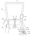
- 1 is a diagram showing an example of a device configuration in a cab of a vehicle body according to an embodiment of the present invention;
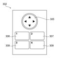
- FIG. 3B is an enlarged plan view of the dial and push button of the control device of FIG. 3A.
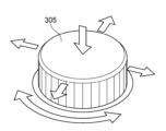
- FIG. 3B is an enlarged perspective view of the dial of the operating device of FIG. 3A.
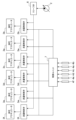
- 1 is a simplified system configuration diagram showing an operation device according to an embodiment of the present invention together with its peripheral configuration.
- 10A to 10C are diagrams illustrating an example of a method for switching functions assigned to rotation operations of a dial according to the embodiment.
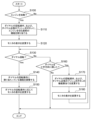
- 5 is a flowchart showing the process of the control device for the operation device according to the present embodiment (during a dial rotation operation and a cross direction operation).
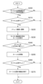
- 5 is a flowchart showing the process of the control device for the operation device according to the present embodiment (when a dial is pressed down).
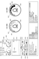
- 11 is a diagram showing an example of a monitor display when a rotation operation of a dial according to the present embodiment is assigned to an engine speed adjustment function;
- FIG. 11 is a diagram showing an example of a monitor display when a rotation operation of a dial according to the embodiment is assigned to an audio volume adjustment function.
- FIG. 11 is a diagram showing an example of a monitor display when a rotation operation of a dial according to the present embodiment is assigned to an air conditioner air volume adjustment function.
- FIG. 11 is a diagram showing an example of a display on a monitor when a cross direction operation of a dial according to the present embodiment is assigned to a cursor movement operation on the screen.
- FIG. 1 is a perspective view showing a schematic external view of a hydraulic excavator shown as an example of a work machine according to this embodiment.
- FIG. 2 is a diagram showing the hydraulic drive system of the hydraulic excavator shown as an example of a work machine according to this embodiment, together with its control unit.
- the hydraulic excavator 1 is made up of a vehicle body (working machine body) 1B consisting of an upper rotating body 1d and a lower running body 1e, and a multi-jointed working device 1A consisting of a boom 1a, arm 1b, and bucket 1c that each rotate vertically and is attached to the front of the upper rotating body 1d, with the base end of the boom 1a of the working device 1A being supported on the front of the upper rotating body 1d.
- the working device 1A is made up of multiple driven members (boom 1a, arm 1b, bucket 1c as an attachment) connected together, and is capable of performing tasks such as excavation and dumping.
- the upper rotating body 1d is rotatably mounted on top of the lower running body 1e, and the upper rotating body 1d is equipped with a driver's room (also called a cab) 1f.
- the boom 1a, arm 1b, bucket 1c, upper rotating body 1d, and lower traveling body 1e in FIG. 1 are driven by hydraulic actuators, namely the boom cylinder 3a, arm cylinder 3b, bucket cylinder 3c, rotating motor 3d, and left and right traveling motors 3e, 3f, shown in FIG. 1 and FIG. 2, respectively, and their operations are commanded by multiple operating lever devices 4a to 4f.
- the multiple operating lever devices 4a to 4f are arranged in the cab 1f in which the operator sits, and command the operations of the multiple hydraulic actuators 3a to 3f according to the amount of operation.
- the hydraulic excavator 1 of this embodiment comprises a hydraulic pump 2, a plurality of hydraulic actuators including a boom cylinder 3a, an arm cylinder 3b, a bucket cylinder 3c, a swing motor 3d, and left and right traveling motors 3e, 3f that are driven by pressurized oil from the hydraulic pump 2, a plurality of operating lever devices 4a-4f provided corresponding to each of these hydraulic actuators 3a-3f, a plurality of flow control valves 5a-5f that are controlled by these operating lever devices 4a-4f and control the flow rate of pressurized oil supplied to the hydraulic actuators 3a-3f, a relief valve 6 that opens when the discharge pressure of the hydraulic pump 2 reaches or exceeds a set value, and a control unit 7 having the function of controlling the flow control valves 5a-5f by inputting an operating signal from the operating lever devices 4a-4f, which constitute a hydraulic drive device that drives a plurality of driven members including the boom 1a, arm 1b, bucket 1c, upper swing body 1d, and lower traveling
- the boom pin, arm pin, and bucket pin of the work device 1A are provided with angle sensors (attitude sensors) 8a, 8b, and 8c that detect the rotation angles of the boom 1a, arm 1b, and bucket 1c.
- the attitude of the work device 1A can be detected based on the angles detected by the angle sensors 8a, 8b, and 8c, and the angle sensors 8a, 8b, and 8c function as attitude sensors that detect the attitude of the work device 1A.
- IMUs inertial measurement units attached to the boom 1a, arm 1b, and bucket 1c, respectively, can be used as attitude sensors for the work device 1A.
- FIGS. 3A, 3B, and 3C are schematic diagrams showing an example of a device installed in the driver's cab 1f of the vehicle body 1B according to this embodiment.
- the lever 301 is a safety device that switches between enabling and disabling the drive of the hydraulic excavator 1 in response to the operation of the operating lever devices 4a to 4f.
- the operating device group 302 (hereinafter sometimes simply referred to as the operating device 302) for using the functions of the hydraulic excavator 1 is composed of a dial operating device 305 and push button operating devices 306 to 309, and each operating device is an input device that can use the functions of the hydraulic excavator 1 of this embodiment. Representative examples of such functions include adjusting the engine speed, operating the wipers, operating the audio system, and operating the air conditioner.
- the dial operating device (also simply referred to as the dial) 305 has a mechanism that allows it to be rotated and moved in a cross direction (up, down, left, right), and to be pushed from top to bottom (see FIG. 3C in particular).
- the push button operating devices (also simply referred to as the push button) 306 to 309 are located near the dial operating device 305 and have a mechanism that allows it to be pushed from top to bottom.
- the monitor 303 is equipped with a touch panel and is a device for presenting various information and using the functions of the hydraulic excavator 1. To operate the monitor 303, the operation device group 302 is used or a touch operation is performed on the monitor 303.
- the engine starter 304 is a device (engine start control device) for controlling the start of the engine of the hydraulic excavator 1.
- the engine starter 304 is provided between the operating lever devices 4a, 4b and the operation device group 302, in other words, in front of the operation device group 302.
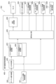
- FIG. 4 is a simplified system configuration diagram showing the operation device according to this embodiment together with the peripheral configuration.
- the hydraulic excavator 1 of this embodiment is provided with an operating device control device (controller) 400 according to this embodiment shown in FIG. 4.
- the operating device control device 400 assigns functions to the operating device group 302, executes functions provided in the hydraulic excavator 1, and displays the information on the monitor 303, etc., in response to signals input by the operator through the operating device group 302 and the engine start control device 401.
- the operating device control device 400 has an input determination unit 402, a switch function assignment processing unit 403, a switch function assignment storage unit 404, a signal output unit 405, and a display processing unit 406, and has the engine start control device 401, the monitor 303, an engine rotation speed control device 407, an audio volume control device 408, and an air conditioner air volume control device 409 as peripheral devices.
- the input determination unit 402 determines whether a rotation operation, a cross-shaped operation, or a pressing operation has been input in response to the operation of the dial operation device 305, and when it is determined that a signal that satisfies the conditions for changing the function allocation of the operation device group 302 has been input, it sends a signal to the switch function allocation processing unit 403.
- the switch function allocation processing unit 403 sends a signal to the signal output unit 405 that switches the function allocation of each switch of the operation device group 302.
- the display processing unit 406 which has received a signal to switch the function allocation of the operation device group 302 from the signal output unit 405, sends a signal to the monitor 303 to display the function allocation status of the operation device group 302.
- the signal output unit 405 also sends a signal to the dial operation device 305 and the push button operation devices 306 to 309 to switch the assigned functions.
- the signal output unit 405 When the signal output unit 405 receives a signal indicating a rotation operation of the dial operation device 305 from the input determination unit 402, it sends a signal to either the engine rotation speed control device 407, the audio volume control device 408, or the air conditioner air volume control device 409 depending on the function assigned to the dial operation device 305, and at the same time sends a signal to switch the display to the monitor 303 via the display processing unit 406.
- the switch function assignment storage unit 404 provided in the switch function assignment processing unit 403 receives a signal sent from the engine start control unit 401 indicating that the engine has been turned off, it stores the functions assigned to the operating devices 302 immediately prior to that.
- the engine start control unit 401 sends a signal indicating that the engine has started to the switch function assignment processing unit 403, which in turn sends a signal to the monitor 303 via the signal output unit 405 and the display processing unit 406 to display the functions assigned immediately prior to engine start, and at the same time assigns the functions assigned immediately prior to engine start to the dial operating device 305 and the push button operating devices 306 to 309.
- FIG. 5 is a diagram showing a schematic diagram of an example of a method for switching the function allocation of the dial operation device 305.
- the rotation operation of the dial operation device 305 is exclusively assigned one of the following functions: an engine speed adjustment function for adjusting the speed of the engine that drives the hydraulic excavator 1 (work device 1A), an audio volume adjustment function for adjusting the volume of the audio played in the cab 1f of the vehicle body 1B, and an air conditioner air volume adjustment function for adjusting the air volume of the air conditioner that conditions the cab 1f of the vehicle body 1B.
- the function assigned to the rotation operation of the dial operation device 305 is the engine RPM adjustment function 500
- tilting the dial operation device 305 to the right switches the function assigned to the rotation operation of the dial operation device 305 to the audio volume adjustment function 502.
- the dial operation device 305 is tilted to the left (505)
- the function assigned to the rotation operation of the dial operation device 305 switches back to the state before switching to the audio volume adjustment function 502, that is, to the engine RPM adjustment function 500.
- the function assigned to the rotation operation of the dial operation device 305 is the engine speed adjustment function 500
- the dial operation device 305 is tilted to the left (506)
- the function assigned to the rotation operation of the dial operation device 305 switches to the air conditioner air volume adjustment function 501.
- the dial operation device 305 is tilted to the right (504)
- the function assigned to the rotation operation of the dial operation device 305 switches back to the state before switching to the air conditioner air volume adjustment function 501, that is, to the engine speed adjustment function 500.
- the function assigned to the rotation operation of the dial operation device 305 is the engine speed adjustment function 500
- the dial operation device 305 is pressed (508)
- the function assigned to the cross-directional operation of the dial operation device 305 is switched to the screen operation function 503 for moving the cursor displayed on the monitor 303.
- FIG. 6 is a flowchart showing the processing contents of the control device for the operation device 400 (when the dial operation device 305 is rotated and operated in the cross direction). The operation based on the flowchart in FIG. 6 is as follows.
- the function to be assigned to the rotation operation of the dial operation device 305 of the operation device group 302 and the function to be assigned to the depression operation of the push button operation devices 306 to 309 are each assigned to the function that was assigned immediately before the engine was turned off.
- S120 The monitor 303 displays a schematic representation of the functions assigned in S110 and the current settings of the assigned functions.
- S140 Adjust the function assigned to the rotation operation of the dial operation device 305. Either the engine speed adjustment function, the audio volume adjustment function, or the air conditioner air volume adjustment function is assigned to the rotation operation of the dial operation device 305, and adjustment is made according to the amount and direction of rotation of the dial operation device 305.
- S170 The function to be assigned to the rotation operation of the dial operation device 305 of the operation device group 302 and the function to be assigned to the depression operation of the push button operation devices 306 to 309 are switched to a function other than the previously assigned function (see FIG. 5).
- S180 The monitor 303 displays a schematic representation of the functions assigned in S170 and the current settings of the assigned functions, and the process proceeds to S130.
- FIG. 7 is a flowchart showing the processing contents of the control device for the operation device 400 (when the dial operation device 305 is pressed). The operation based on the flowchart in FIG. 7 is as follows.
- the screen displayed on the monitor 303 transitions to a menu screen.
- the menu screen is a screen that displays a menu that allows the user to change the settings of the vehicle and check information related to the vehicle, for example.
- S230 The cursor is displayed on the item to be operated on in the menu screen displayed in S220.
- a cursor for screen operation is displayed on the monitor 303 on which the menu screen is displayed.
- S250 The position of the cursor displayed in S230 moves according to the direction in which the dial operation device 305 is tilted in S240. As described above, when the dial operation device 305 is pressed down to allow the cross-directional operation of the dial operation device 305 to be used to move the cursor within the monitor 303, the rotation operation of the dial operation device 305 is disabled.
- S270 The function assigned to the cursor position moved to in S250 is executed. As an example, a screen for setting the function at the cursor position is displayed. As described above, by pressing the dial operation device 305 once and then pressing it again, the rotation operation of the dial operation device 305 is made valid.
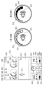
- FIG. 8 is a schematic diagram showing an example of a display on the monitor 303 relating to the basic functions of the shovel and a display in which the function assigned to the rotation operation of the dial operation device 305 is the engine speed adjustment function.
- a display 815 indicating that when the dial operation device 305 is tilted to the right, the rotation operation of the dial operation device 305 will switch to an audio volume adjustment function
- a display 814 indicating that when the dial operation device 305 is tilted to the left, the rotation operation of the dial operation device 305 will switch to an air conditioner air volume adjustment function.
- Display 814 can also be used to switch the rotation operation of the dial operation device 305 to the air conditioner air volume adjustment function by touching the monitor 303.
- Display 815 can also be used to switch the rotation operation of the dial operation device 305 to the audio volume adjustment function by touching the monitor 303.
- a design 820 is displayed that indicates that an engine speed adjustment function has been assigned, and as the engine speed is adjusted, a design 822 that indicates the adjustment stage changes between a display 821 that indicates the minimum stage and a display 823 that indicates the maximum stage.
- the displays 816-819 of the functions assigned to the push button operation devices 306-309 mimic the shape of the buttons on the actual push button operation devices 306-309, and the functions are executed by pressing the push button operation devices 306-309 or touching the displays 816-819 on the monitor 303.
- the push button operation devices 306 to 309 are assigned functions according to the function (here, the engine speed adjustment function) assigned to the rotation operation of the dial operation device 305.
- the functions assigned to the push button operation devices 306 to 309 are displayed as follows: Display 816 indicating the function assigned to the push button operation device 306: Switching the travel speed mode of the lower traveling body 1e Display 818 indicating the function assigned to the push button operation device 307: Switching the operating speed of the upper rotating body 1d Display 817 indicating the function assigned to the push button operation device 308: Wiper function Display 819 indicating the function assigned to the push button operation device 309: Windshield washer function
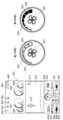
- FIG. 9 is a schematic diagram showing an example of a display on monitor 303 relating to the basic functions of a shovel and a display in which the function assigned to the rotation operation of dial operation device 305 is an audio volume adjustment function.
- the display (design) 824 that imitates the dial operation device 305 there is a display 825 that indicates that tilting the dial operation device 305 to the left will switch the rotation operation of the dial operation device 305 to the engine speed adjustment function.
- the display 825 can also be used to switch the rotation operation of the dial operation device 305 to the engine speed adjustment function by touching the monitor 303.
- a design 830 is displayed that indicates that an audio volume adjustment function has been assigned, and as the audio volume is adjusted, a design 832 that indicates the adjustment level changes between a display 831 that indicates the minimum level and a display 833 that indicates the maximum level.
- the displays 826-829 of the functions assigned to the push button operation devices 306-309 mimic the shape of the buttons on the actual push button operation devices 306-309, and the functions are executed by pressing the push button operation devices 306-309 or touching the displays 826-829 on the monitor 303.
- the push button operation devices 306 to 309 are assigned functions according to the function (here, audio volume adjustment function) assigned to the rotation operation of the dial operation device 305.
- the functions assigned to the push button operation devices 306 to 309 are displayed as follows: Display 826 indicating the function assigned to the push button operation device 306: Switching to the radio station previous to the currently selected radio station.
- Display 828 indicating the function assigned to the push button operation device 307: Switching to the radio station next to the currently selected radio station.
- FIG. 10 is a schematic diagram showing an example of a display on monitor 303 relating to the basic functions of a shovel and a display in which the function assigned to the rotation of dial operation device 305 is the air conditioner air volume adjustment function.
- a display 835 that indicates that tilting the dial operation device 305 to the right will switch the rotation operation of the dial operation device 305 to the engine speed adjustment function.
- the display 835 can also be used to switch the rotation operation of the dial operation device 305 to the engine speed adjustment function by touching the monitor 303.
- a design 843 is displayed that indicates that the air conditioner air volume adjustment function is assigned, and as the air conditioner air volume is adjusted, a design 845 that indicates the adjustment stage changes between a display 844 indicating the minimum stage and a display 846 indicating the maximum stage.
- the displays 839-842 of the functions assigned to the push button operation devices 306-309 mimic the shape of the buttons on the actual push button operation devices 306-309, and the functions are executed by pressing the push button operation devices 306-309 or touching the displays 839-842 on the monitor 303.
- the push button operation devices 306 to 309 are assigned functions according to the function (here, the air conditioner air volume adjustment function) assigned to the rotation operation of the dial operation device 305.
- the functions assigned to the push button operation devices 306 to 309 are displayed as follows: Display 839 showing the function assigned to the push button operation device 306: Turning on and off the recirculated air inside.
- Display 841 showing the function assigned to the push button operation device 307: Turning on and off the automatic air conditioner.
- Display 842 showing the function assigned to the push button operation device 309: Turning on and off the air conditioner power.
- Displays 836 showing the currently set temperature of the air conditioner displays 837 showing the status of the internal air circulation, the air outlet, and the automatic air conditioner, and display 838 showing the current air volume setting of the air conditioner. These displays are always displayed even if the function assigned to the rotation of the dial operation device 305 is something other than the air conditioner air volume adjustment function.
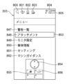
- FIG. 11 is a schematic diagram showing a menu screen on which the shovel's functions can be set and information can be viewed, as an example of a display on monitor 303 relating to the basic functions of the shovel and a display in which the functions assigned to the crosswise operations of dial operation device 305 are screen operation functions.
- cursor 853 is on attachment 848 of menu items 847 to 852 and dial operation device 305 is tilted upward, cursor 853 moves to warning list 847, and when dial operation device 305 is tilted downward, cursor 853 moves to monitor settings 849.
- the functions of menu items 847 to 852 displayed on monitor 303 can also be executed by touching monitor 303.
- Functions are assigned to the push button operation devices 306 to 309 according to the screen operation functions assigned to the pressing operations of the dial operation device 305.
- the displays showing the functions assigned to the push button operation devices 306 to 307 are as follows. The functions are executed by pressing the push button operation devices 306 to 307 or touching the displays 855 to 856 on the monitor 303.
- the engine speed adjustment function which affects the efficiency of the work itself, is positioned between the audio volume adjustment function and the air conditioner air volume adjustment function as functions assigned to the rotation operation of the dial operation device 305 (see FIG. 5). Therefore, if the engine speed adjustment function is thought of as the function assigned to the rotation operation of the dial operation device 305 during work, the operator can efficiently adjust the audio volume and the air conditioner air volume, and at the same time, it is easy for him or her to remember how to switch between functions assigned to the rotation operation of the dial operation device 305.
- the monitor 303 displays the functions assigned to the rotation operation of the dial operation device 305 and the setting status of those functions (813, 824, 834), so that the functions assigned to the rotation operation of the dial operation device 305 can be adjusted while watching the monitor 303, and the camera image 810 can be instantly viewed when it is necessary to check the safety of the surroundings.
- the operation device group 302 is provided with push button devices 306 to 309 near the dial operation device 305 to which functions are assigned according to the functions assigned to the rotation operation of the dial operation device 305, so that functions related to the functions assigned to the rotation operation of the dial operation device 305 can be efficiently operated.
- the function assignment switching of the rotation operation of the dial operation device 305 is performed by operating the dial operation device 305 in a cross direction, but it may be performed by an operation in a direction different from the rotation operation of the dial operation device 305. For example, it may be performed by accepting and operating in an I-shaped direction, a T-shaped direction, or an L-shaped direction depending on the number of functions.
- the cross direction operation of the dial operation device 305 is performed by tilting (tilting) the dial operation device 305 up, down, left, or right, but it may also be performed by sliding it up, down, left, or right.
- the operation device 302 of this embodiment includes a dial (dial operation device 305) (installed in the cab of a work machine composed of an upper rotating body and a lower traveling body) that accepts a rotation operation and an operation in a direction (cross direction) different from the rotation operation, and a controller (operation device control device 400) that switches a function to be assigned to the rotation operation of the dial, when an operation in a direction (cross direction) different from the rotation operation of the dial is accepted, to a first adjustment function which is an engine rotation speed adjustment function that adjusts the engine speed, and a second adjustment function which is at least one of an audio volume adjustment function that adjusts the volume of an audio device and an air conditioner air volume adjustment function that adjusts the air volume of an air conditioner (i.e., an engine rotation speed adjustment function and an audio volume adjustment function, an engine rotation speed adjustment function and an air conditioner air volume adjustment function, or an engine rotation speed adjustment function, an audio volume adjustment function and an air conditioner air volume adjustment function), and exclusively assigns a dial (dial operation device 305) (installe
- the operation of the dial in a direction different from the rotation operation is an operation of tilting or sliding the dial (cross direction). That is, when the controller (control device for operation device 400) receives an operation of tilting or sliding the dial (cross direction), it switches the function assigned to the rotation operation of the dial between a first adjustment function, which is the engine speed adjustment function, and a second adjustment function, which is at least one of the audio volume adjustment function and the air conditioner air volume adjustment function.
- a first adjustment function which is the engine speed adjustment function
- a second adjustment function which is at least one of the audio volume adjustment function and the air conditioner air volume adjustment function.
- the controller switches the function assigned to the rotation operation of the dial to the engine speed adjustment function, the audio volume adjustment function, and the air conditioner air volume adjustment function in response to receiving an operation in a direction different from the rotation operation of the dial (cross direction), and exclusively assigns one of the engine speed adjustment function, the audio volume adjustment function, and the air conditioner air volume adjustment function to the rotation operation of the dial, and the order in which the functions assigned to the rotation operation of the dial are switched in response to receiving an operation in a direction different from the rotation operation of the dial is such that the engine speed adjustment function is positioned between the audio volume adjustment function and the air conditioner air volume adjustment function.
- the controller switches the function assigned to the rotation operation of the dial to the audio volume adjustment function
- the controller switches the function assigned to the rotation operation of the dial to the air conditioner air volume adjustment function
- controller controls the function assigned to the rotation operation of the dial to the audio volume adjustment function
- the controller receives an operation of the dial in one direction (tilt to the right) different from the rotation operation of the dial while the engine speed adjustment function is assigned to the rotation operation of the dial
- the controller receives an operation of the dial in the opposite direction (tilt to the left) from the one direction while the audio volume adjustment function is assigned to the rotation operation of the dial
- the function assigned to the rotation operation of the dial to the same as before switching to the audio volume adjustment function)
- the function assigned to the rotation operation of the dial is switched to the air conditioner air volume adjustment function
- the function assigned to the dial is switched to the air conditioner air volume adjustment function
- the rotation operation of the dial is assigned to the air conditioner air volume adjustment function and an operation of the dial in one direction (tilt to the right) is received
- the function assigned to the rotation operation of the dial is switched to the air conditioner air volume adjustment function
- the controller assigns the function that was assigned to the rotation operation of the dial immediately before the engine was turned off to the rotation operation of the dial the next time the engine is started.
- buttons Push button operation devices 306-309 to which functions are assigned according to the functions assigned to the rotation operation of the dial.
- the work machine (hydraulic excavator 1) of this embodiment also includes a work machine main body 1B, a work device 1A that is attached to the work machine main body 1B and performs work, an engine that drives the work device 1A, a cab 1f in which an operator sits, at least one of audio that is played in the cab 1f or an air conditioner that conditions the cab 1f, a dial (dial operation device 305) that accepts rotational operation and operation in a direction different from the rotational operation (cross direction), and a function that is assigned to the rotational operation of the dial when an operation in a direction different from the rotational operation of the dial (cross direction) is accepted, the first adjustment function being an engine speed adjustment function that adjusts the rotational speed of the engine, an audio volume adjustment function that adjusts the volume of the audio, or a wind adjustment function that adjusts the wind volume of the air conditioner.
- a second adjustment function that is at least one of the functions of the air conditioner air volume adjustment function that adjusts the volume of the engine speed (i.e., engine speed adjustment function and audio volume adjustment function, engine speed adjustment function and air conditioner air volume adjustment function, or engine speed adjustment function, audio volume adjustment function and air conditioner air volume adjustment function), and exclusively assigns to the rotation operation of the dial either the first adjustment function, which is the engine speed adjustment function, or the second adjustment function, which is at least one of the functions of the audio volume adjustment function and the air conditioner air volume adjustment function; and a (touch-operable) monitor 303 that is arranged in the cab 1f and displays the state of the function assigned to the rotation operation of the dial.
- Push buttons are arranged to which functions are assigned according to the functions assigned to the rotation operation of the dial, and the monitor 303 displays the status of the functions assigned to the push buttons along with the status of the functions assigned to the rotation operation of the dial.
- the operation of the dial in a direction different from the rotation operation is a cross-directional operation of the dial, and the cross-directional operation of the dial can be used for screen operation (cursor movement) within the monitor 303 in addition to switching the function assigned to the rotation operation of the dial, and when the cross-directional operation of the dial can be used for screen operation (cursor movement) within the monitor 303, the rotation operation of the dial is disabled.
- An operation of the dial in a direction different from the rotation operation is a pressing operation of the dial, and by pressing the dial, the cross-directional operation of the dial is made available for screen operation (cursor movement) within the monitor 303, and the rotation operation of the dial is made invalid.
- the rotation of the dial is made valid by pressing the dial again after pressing the dial.
- the operating device 302 of this embodiment is, for example, a dial that has a rotation mechanism and a mechanism that can be tilted in a cross direction, and the rotation operation of the dial can be exclusively assigned to an engine speed adjustment function, an audio volume adjustment function, and an air conditioner air volume adjustment function.
- the engine speed adjustment function first adjustment function
- tilting the dial in one of the cross directions switches the assignment of the rotation operation of the dial to the audio volume adjustment function or the air conditioner air volume adjustment function (second adjustment function).
- the audio volume can be adjusted instantly.
- the air conditioner's air volume can be adjusted instantly.
- the present invention is not limited to the above-described embodiments, but includes various modified forms.
- the above-described embodiments have been described in detail to clearly explain the present invention, and are not necessarily limited to those including all of the configurations described. It is also possible to replace part of the configuration of one embodiment with the configuration of another embodiment, and it is also possible to add the configuration of another embodiment to the configuration of one embodiment. It is also possible to add, delete, or replace part of the configuration of each embodiment with other configurations.
- the configurations of the control device 400 described above and the functions and execution processes of the configurations may be realized in part or in whole by hardware (for example, by designing the logic that executes each function in an integrated circuit).
- the configurations of the control device 400 described above may be programs (software) that are read and executed by an arithmetic processing device (for example, a CPU) to realize the functions of the configurations of the control device 400.
- Information related to the programs may be stored, for example, in semiconductor memory (flash memory, SSD, etc.), magnetic storage devices (hard disk drives, etc.), and recording media (magnetic disks, optical disks, etc.).
- control lines and information lines are those that are considered necessary for the description of the embodiment, but they do not necessarily show all the control lines and information lines related to the product. In reality, it can be considered that almost all components are interconnected.
- Hydraulic excavator (work machine) 1A Working device 1B Vehicle body (working machine body) 1a Boom 1b Arm 1c Bucket 1d Upper rotating body 1e Lower traveling body 1f Cab 2 Hydraulic pumps 3a to 3f Hydraulic actuators 4a to 4f Operation lever device 5a to 5f Flow control valve 6 Relief valve 7 Control unit 301 Lever (safety device for enabling/disabling the operation of 4a to 4f) 302 Operation device group (operation device) 303 monitor 304 engine starter 305 dial operation device (dial) 306 to 309 Push button operation device (push button) 400 Control device for operation device (controller) 401 Engine start control device 402 Input determination unit 403 Switch function assignment processing unit 404 Switch function assignment storage unit 405 Signal output unit 406 Display processing unit
Landscapes
- Engineering & Computer Science (AREA)
- Chemical & Material Sciences (AREA)
- Mechanical Engineering (AREA)
- Transportation (AREA)
- Combustion & Propulsion (AREA)
- General Engineering & Computer Science (AREA)
- Structural Engineering (AREA)
- Civil Engineering (AREA)
- Mining & Mineral Resources (AREA)
- Theoretical Computer Science (AREA)
- Mechanical Control Devices (AREA)
- Human Computer Interaction (AREA)
- Physics & Mathematics (AREA)
- General Physics & Mathematics (AREA)
Abstract
Description
プッシュボタン操作装置306に割り当たっている機能を示す表示816:下部走行体1eの走行速度モードを切り替える
プッシュボタン操作装置307に割り当たっている機能を示す表示818:上部旋回体1dの動作速度を切り替える
プッシュボタン操作装置308に割り当たっている機能を示す表示817:ワイパー機能
プッシュボタン操作装置309に割り当たっている機能を示す表示819:前窓のウォッシャー機能
プッシュボタン操作装置306に割り当たっている機能を示す表示826:現在選局されているラジオ局の前の放送局に切り替える
プッシュボタン操作装置307に割り当たっている機能を示す表示828:現在選局されているラジオ局の次の放送局に切り替える
プッシュボタン操作装置308に割り当たっている機能を示す表示827:オーディオソースの切り替え
プッシュボタン操作装置309に割り当たっている機能を示す表示829:オーディオ電源のオン、オフ
プッシュボタン操作装置306に割り当たっている機能を示す表示839:内気循環のオン、オフ
プッシュボタン操作装置307に割り当たっている機能を示す表示841:オートエアコンのオン、オフ
プッシュボタン操作装置308に割り当たっている機能を示す表示840:吹き出し口の切り替え
プッシュボタン操作装置309に割り当たっている機能を示す表示842:エアコン電源のオン、オフ
プッシュボタン操作装置306に割り当たっている機能を示す表示855:一つ前の階層に戻る
プッシュボタン操作装置307に割り当たっている機能を示す表示856:ホーム画面(ダイヤル操作装置305の回転操作に割り当たる機能がエンジン回転数調整機能になっている状態)に切り替える
従来技術のように、ダイヤルの回転操作に、エンジンの回転数を調節する機能と、モニタに表示された画面に応じた操作を行う画面操作機能を選択的に割り当てることができる操作装置を用いた場合、エンジン回転数を調整した後に、オーディオ音量を調整するためには、ダイヤルの回転操作に割り当てる機能を何らかの操作によって画面操作機能に切り替えてから、その後にオーディオ音量調整機能にカーソルを移動させた上でオーディオ音量を調整することになるため、即座にオーディオ音量を調整することが難しい。一方、従来技術の操作装置とは別にオーディオ音量調整機能専用のダイヤル操作装置を用意した場合、エンジン回転数を調整した後に、一度ダイヤルから手を放してから、オーディオ音量を調整するための操作装置に持ち替えて操作する必要があるため、即座にオーディオ音量を調整することが難しい。
これに対して、本実施形態においては、ダイヤル操作装置305から手を放さなくても、ダイヤル操作装置305を右方向に一度倒すだけで、ダイヤルの回転操作に割り当たる機能が、エンジン回転数調整機能から、オーディオ音量調整機能に切り替わるため、エンジン回転数を調整した結果に伴うオーディオ音量の聴こえ方の変化に対して、即座にオーディオ音量を調整することが可能である。また、オーディオ音量調整後は、ダイヤル操作装置305を左方向に一度倒すだけで、ダイヤルの回転操作の割り当てをエンジン回転数調整機能に切り替えることが可能であるため、効率的に作業を継続することができる。その他の本実施形態に係る効果としては、以下の効果2~6の点が挙げられる。
エンジン回転数、オーディオ音量と並んで、ダイヤルの回転操作で調整することが一般的かつ効率的な機能として、エアコン風量調整機能があるが、これに対しても、ダイヤル操作装置305の回転操作に割り当たっている機能が、エンジン回転数調整機能の状態から、ダイヤル操作装置305を左方向に一度倒すだけで、エアコン風量調整機能に切り替えることが可能であるため、効率的にエアコン風量の調整ができる。
作業自体の効率に影響を与えるエンジン回転数調整機能が、ダイヤル操作装置305の回転操作に割り当たる機能として、オーディオ音量調整機能とエアコン風量調整機能の中間に位置する(図5参照)ため、作業中のダイヤル操作装置305の回転操作に割り当たっている機能がエンジン回転数調整機能と考えると、オペレータは効率的にオーディオ音量とエアコン風量を調整できると同時に、ダイヤル操作装置305の回転操作に割り当てる機能の切り替え方法を覚えやすい。
モニタ303には、ダイヤル操作装置305の回転操作に割り当たっている機能およびその機能の設定状態が表示される(813、824、834)ため、モニタ303を見ながらダイヤル操作装置305の回転操作に割り当たっている機能を調整しつつ、周囲の安全確認が必要な時にはカメラ映像810を即座に見ることができる。
操作装置群302には、ダイヤル操作装置305の付近に、ダイヤル操作装置305の回転操作に割り当たる機能に応じて機能が割り当たるプッシュボタン装置306~309が備わるため、ダイヤル操作装置305の回転操作に割り当たる機能に関連する機能を効率的に操作することができる。
モニタ303には、操作装置群302を模した表示があるため、操作装置群302のダイヤル操作装置305およびプッシュボタン操作装置306~309に機能を示す印字がされていなくても、ダイヤル操作装置305およびプッシュボタン操作装置306~309に割り当たっている機能の対応関係が分かりやすい。
以上説明したように、本実施形態の操作装置302は、(上部旋回体と下部走行体から構成される作業機械の運転室内に設置される)回転操作および回転操作と異なる方向(十字方向)の操作を受け付けるダイヤル(ダイヤル操作装置305)と、前記ダイヤルの前記回転操作と異なる方向(十字方向)の操作を受け付けたときに、前記ダイヤルの前記回転操作に割り当てる機能を、エンジンの回転数を調整するエンジン回転数調整機能である第1調整機能、およびオーディオの音量を調整するオーディオ音量調整機能とエアコンの風量を調整するエアコン風量調整機能のうち少なくともいずれか一方の機能である第2調整機能(すなわち、エンジン回転数調整機能とオーディオ音量調整機能、エンジン回転数調整機能とエアコン風量調整機能、あるいは、エンジン回転数調整機能とオーディオ音量調整機能とエアコン風量調整機能)に切り替え、前記ダイヤルの前記回転操作に、前記エンジン回転数調整機能である第1調整機能と、前記オーディオ音量調整機能または前記エアコン風量調整機能のうち少なくともいずれか一方の機能である第2調整機能とのうちのいずれかの機能を排他的に割り当てるコントローラ(操作装置用制御装置400)と、を備える。
1A 作業装置
1B 車体(作業機械本体)
1a ブーム
1b アーム
1c バケット
1d 上部旋回体
1e 下部走行体
1f 運転室
2 油圧ポンプ
3a~3f 油圧アクチュエータ
4a~4f 操作レバー装置
5a~5f 流量制御弁
6 リリーフ弁
7 制御ユニット
301 レバー(4a~4fの操作を有効・無効にするための安全装置)
302 操作装置群(操作装置)
303 モニタ
304 エンジンスタータ
305 ダイヤル操作装置(ダイヤル)
306~309 プッシュボタン操作装置(プッシュ式ボタン)
400 操作装置用制御装置(コントローラ)
401 エンジン始動制御装置
402 入力判定部
403 スイッチ機能割当て処理部
404 スイッチ機能割当て記憶部
405 信号出力部
406 表示処理部
Claims (11)
- 回転操作および回転操作と異なる方向の操作を受け付けるダイヤルと、
前記ダイヤルの前記回転操作と異なる方向の操作を受け付けたときに、前記ダイヤルの前記回転操作に割り当てる機能を、エンジンの回転数を調整するエンジン回転数調整機能である第1調整機能、およびオーディオの音量を調整するオーディオ音量調整機能とエアコンの風量を調整するエアコン風量調整機能のうち少なくともいずれか一方の機能である第2調整機能に切り替えるコントローラと、を備えることを特徴とする操作装置。 - 請求項1に記載の操作装置において、
前記ダイヤルの前記回転操作と異なる方向の操作は、前記ダイヤルの傾斜またはスライド方向の操作であることを特徴とする操作装置。 - 請求項1に記載の操作装置において、
前記コントローラは、前記ダイヤルの前記回転操作と異なる方向の操作を受け付けたことに応じて、前記ダイヤルの前記回転操作に割り当てる機能を、前記エンジン回転数調整機能と、前記オーディオ音量調整機能と、前記エアコン風量調整機能とに、切り替え、
前記ダイヤルの前記回転操作と異なる方向の操作を受け付けたことに応じて前記ダイヤルの前記回転操作に割り当てられる機能の切り替えられる順番は、前記エンジン回転数調整機能が、前記オーディオ音量調整機能と前記エアコン風量調整機能の間に位置した順番となっていることを特徴とする操作装置。 - 請求項3に記載の操作装置において、
前記コントローラは、
前記ダイヤルの前記回転操作に前記エンジン回転数調整機能が割り当たっている状態で、前記ダイヤルの前記回転操作と異なる一方向の操作を受け付けたときに、前記ダイヤルの前記回転操作に割り当たる機能を、前記オーディオ音量調整機能に切り替え、
前記ダイヤルの前記回転操作に前記エンジン回転数調整機能が割り当たっている状態で、前記ダイヤルの前記一方向とは逆方向の操作を受け付けたときに、前記ダイヤルの前記回転操作に割り当たる機能を、前記エアコン風量調整機能に切り替えることを特徴とする操作装置。 - 請求項3に記載の操作装置において、
前記コントローラは、
前記ダイヤルの前記回転操作に前記エンジン回転数調整機能が割り当たっている状態で、前記ダイヤルの前記回転操作と異なる一方向の操作を受け付けたときに、前記ダイヤルの前記回転操作に割り当たる機能を、前記オーディオ音量調整機能に切り替え、
前記ダイヤルの前記回転操作に前記オーディオ音量調整機能が割り当たっている状態で、前記ダイヤルの前記一方向とは逆方向の操作を受け付けたときに、前記ダイヤルの前記回転操作に割り当たる機能を、前記エンジン回転数調整機能に切り替え、
前記ダイヤルの前記回転操作に前記エンジン回転数調整機能が割り当たっている状態で、前記ダイヤルの前記逆方向の操作を受け付けたときに、前記ダイヤルの前記回転操作に割り当たる機能を、前記エアコン風量調整機能に切り替え、
前記ダイヤルの前記回転操作に前記エアコン風量調整機能が割り当たっている状態で、前記ダイヤルの前記一方向の操作を受け付けたときに、前記ダイヤルの前記回転操作に割り当たる機能を、前記エンジン回転数調整機能に切り替えることを特徴とする操作装置。 - 請求項1に記載の操作装置において、
前記コントローラは、前記エンジンを切る直前に前記ダイヤルの前記回転操作に割り当たっていた機能を、次回エンジン始動時の前記ダイヤルの前記回転操作に割り当てることを特徴とする操作装置。 - 請求項1に記載の操作装置において、
前記ダイヤルの付近には、前記ダイヤルの前記回転操作に割り当たっている機能に応じて機能が割り当たるプッシュ式ボタンが配置されていることを特徴とする操作装置。 - 作業機械本体と、
前記作業機械本体に取り付けられ、作業を実行する作業装置と、
前記作業装置を駆動するエンジンと、
オペレータが搭乗する運転室と、
前記運転室で再生されるオーディオまたは前記運転室の空調を行うエアコンのうち少なくともいずれか一方の機器と、
回転操作および回転操作と異なる方向の操作を受け付けるダイヤルと、
前記ダイヤルの前記回転操作と異なる方向の操作を受け付けたときに、前記ダイヤルの前記回転操作に割り当てる機能を、前記エンジンの回転数を調整するエンジン回転数調整機能である第1調整機能と、前記オーディオの音量を調整するオーディオ音量調整機能または前記エアコンの風量を調整するエアコン風量調整機能のうち少なくともいずれか一方の機能である第2調整機能と、を切り替えるコントローラと、
前記運転室に配置され、前記ダイヤルの前記回転操作に割り当たっている機能の状態を表示するモニタと、を備えることを特徴とする作業機械。 - 請求項8に記載の作業機械において、
前記ダイヤルの前記回転操作と異なる方向の操作は、前記ダイヤルの十字方向の操作であり、前記ダイヤルの前記十字方向の操作は、前記ダイヤルの前記回転操作に割り当てる機能の切り替え操作以外に、前記モニタ内の画面操作に使用可能であり、前記ダイヤルの前記十字方向の操作が前記モニタ内の画面操作に使用可能であるときには、前記ダイヤルの前記回転操作は無効とされていることを特徴とする作業機械。 - 請求項9に記載の作業機械において、
前記ダイヤルの前記回転操作と異なる方向の操作は、前記ダイヤルの押下操作であり、前記ダイヤルの前記押下操作によって、前記ダイヤルの前記十字方向の操作は、前記モニタ内の画面操作に使用可能とされ、前記ダイヤルの前記回転操作は無効とされることを特徴とする作業機械。 - 請求項10に記載の作業機械において、
前記ダイヤルの前記押下操作後の再度の押下操作によって、前記ダイヤルの前記回転操作は有効とされることを特徴とする作業機械。
Priority Applications (4)
| Application Number | Priority Date | Filing Date | Title |
|---|---|---|---|
| CN202480052508.8A CN121752787A (zh) | 2023-09-27 | 2024-05-22 | 操作装置以及具有该操作装置的作业机械 |
| JP2025548480A JPWO2025069554A1 (ja) | 2023-09-27 | 2024-05-22 | |
| EP24871365.3A EP4756137A1 (en) | 2023-09-27 | 2024-05-22 | Operation device and work machine provided with same |
| KR1020267003966A KR20260039732A (ko) | 2023-09-27 | 2024-05-22 | 조작 장치, 및 그것을 구비한 작업 기계 |
Applications Claiming Priority (2)
| Application Number | Priority Date | Filing Date | Title |
|---|---|---|---|
| JP2023-166402 | 2023-09-27 | ||
| JP2023166402 | 2023-09-27 |
Publications (1)
| Publication Number | Publication Date |
|---|---|
| WO2025069554A1 true WO2025069554A1 (ja) | 2025-04-03 |
Family
ID=95202795
Family Applications (1)
| Application Number | Title | Priority Date | Filing Date |
|---|---|---|---|
| PCT/JP2024/018775 Ceased WO2025069554A1 (ja) | 2023-09-27 | 2024-05-22 | 操作装置、および、それを備えた作業機械 |
Country Status (5)
| Country | Link |
|---|---|
| EP (1) | EP4756137A1 (ja) |
| JP (1) | JPWO2025069554A1 (ja) |
| KR (1) | KR20260039732A (ja) |
| CN (1) | CN121752787A (ja) |
| WO (1) | WO2025069554A1 (ja) |
Citations (3)
| Publication number | Priority date | Publication date | Assignee | Title |
|---|---|---|---|---|
| JPH08227314A (ja) * | 1995-02-20 | 1996-09-03 | Tokai Rika Co Ltd | 制御装置及び自動車 |
| JP2003054290A (ja) * | 2001-08-20 | 2003-02-26 | Denso Corp | 車両用スイッチ装置 |
| JP2022026000A (ja) | 2020-07-30 | 2022-02-10 | ヤンマーホールディングス株式会社 | 操作装置、作業車両、および、操作制御方法 |
-
2024
- 2024-05-22 JP JP2025548480A patent/JPWO2025069554A1/ja active Pending
- 2024-05-22 WO PCT/JP2024/018775 patent/WO2025069554A1/ja not_active Ceased
- 2024-05-22 KR KR1020267003966A patent/KR20260039732A/ko active Pending
- 2024-05-22 EP EP24871365.3A patent/EP4756137A1/en active Pending
- 2024-05-22 CN CN202480052508.8A patent/CN121752787A/zh active Pending
Patent Citations (3)
| Publication number | Priority date | Publication date | Assignee | Title |
|---|---|---|---|---|
| JPH08227314A (ja) * | 1995-02-20 | 1996-09-03 | Tokai Rika Co Ltd | 制御装置及び自動車 |
| JP2003054290A (ja) * | 2001-08-20 | 2003-02-26 | Denso Corp | 車両用スイッチ装置 |
| JP2022026000A (ja) | 2020-07-30 | 2022-02-10 | ヤンマーホールディングス株式会社 | 操作装置、作業車両、および、操作制御方法 |
Also Published As
| Publication number | Publication date |
|---|---|
| CN121752787A (zh) | 2026-03-27 |
| KR20260039732A (ko) | 2026-03-20 |
| EP4756137A1 (en) | 2026-06-10 |
| JPWO2025069554A1 (ja) | 2025-04-03 |
Similar Documents
| Publication | Publication Date | Title |
|---|---|---|
| US12024858B2 (en) | Shovel and shovel operating device | |
| US8972124B2 (en) | Work vehicle | |
| JP7741250B2 (ja) | 油圧ショベルの表示システム | |
| US12195946B2 (en) | Construction machine | |
| US20240018742A1 (en) | Shovel | |
| JP2020049960A (ja) | 船外機のチルト・トリムシステム | |
| CN116171237A (zh) | 操作装置、作业车辆以及操作控制方法 | |
| JP2012225004A (ja) | 作業機械の表示装置 | |
| JP2006107461A (ja) | 作業機械の応答性をカスタム化するためのシステム | |
| JP7382876B2 (ja) | ショベル | |
| KR20260039732A (ko) | 조작 장치, 및 그것을 구비한 작업 기계 | |
| EP4019811A1 (en) | Hydraulic transmission system with configurable virtual gears | |
| WO2017110520A1 (ja) | 表示装置 | |
| JP2000103596A (ja) | 作業機の油圧駆動制御装置 | |
| JP2002173956A (ja) | 油圧ショベルのモニタ装置 | |
| JP7689168B2 (ja) | 作業機械 | |
| JP5762509B2 (ja) | 作業車両 | |
| JP2025097737A (ja) | 表示制御装置、作業機、プログラム、及びその記録媒体 | |
| WO2025134652A1 (ja) | 作業機 | |
| KR20200075158A (ko) | 디스플레이를 구비한 조작계를 이용한 차량용 제어 장치 및 그 제어 방법 | |
| JP2025097736A (ja) | 作業機 | |
| JP2025097738A (ja) | 表示制御装置、作業機、プログラム、及びその記録媒体 | |
| JP2026032723A (ja) | 作業車両の表示システム及び作業車両の表示方法 | |
| JP2011080259A (ja) | 作業機の表示装置 |
Legal Events
| Date | Code | Title | Description |
|---|---|---|---|
| 121 | Ep: the epo has been informed by wipo that ep was designated in this application |
Ref document number: 24871365 Country of ref document: EP Kind code of ref document: A1 |
|
| DPE1 | Request for preliminary examination filed after expiration of 19th month from priority date (pct application filed from 20040101) | ||
| ENP | Entry into the national phase |
Ref document number: 1020267003966 Country of ref document: KR Free format text: ST27 STATUS EVENT CODE: A-0-1-A10-A15-NAP-PA0105 (AS PROVIDED BY THE NATIONAL OFFICE) |
|
| WWE | Wipo information: entry into national phase |
Ref document number: 1020267003966 Country of ref document: KR |
|
| ENP | Entry into the national phase |
Ref document number: 2025548480 Country of ref document: JP Kind code of ref document: A |
|
| WWE | Wipo information: entry into national phase |
Ref document number: 2025548480 Country of ref document: JP |
|
| WWE | Wipo information: entry into national phase |
Ref document number: 2024871365 Country of ref document: EP |
|
| WWP | Wipo information: published in national office |
Ref document number: 1020267003966 Country of ref document: KR |
|
| NENP | Non-entry into the national phase |
Ref country code: DE |