WO2025069293A1 - フィルタ作成方法、フィルタ作成装置、プログラム、およびフィルタ装置 - Google Patents
フィルタ作成方法、フィルタ作成装置、プログラム、およびフィルタ装置 Download PDFInfo
- Publication number
- WO2025069293A1 WO2025069293A1 PCT/JP2023/035351 JP2023035351W WO2025069293A1 WO 2025069293 A1 WO2025069293 A1 WO 2025069293A1 JP 2023035351 W JP2023035351 W JP 2023035351W WO 2025069293 A1 WO2025069293 A1 WO 2025069293A1
- Authority
- WO
- WIPO (PCT)
- Prior art keywords
- pedestrians
- route
- pedestrian
- filter
- control device
- Prior art date
- Legal status (The legal status is an assumption and is not a legal conclusion. Google has not performed a legal analysis and makes no representation as to the accuracy of the status listed.)
- Pending
Links
Images





Classifications
-
- G—PHYSICS
- G05—CONTROLLING; REGULATING
- G05D—SYSTEMS FOR CONTROLLING OR REGULATING NON-ELECTRIC VARIABLES
- G05D1/00—Control of position, course, altitude or attitude of land, water, air or space vehicles, e.g. using automatic pilots
- G05D1/40—Control within particular dimensions
- G05D1/43—Control of position or course in two dimensions [2D]
Definitions
- the present invention relates to a filter creation method, a filter creation device, a program, and a filter device.
- Patent Document 1 An invention for a driving control device related to micromobility has been disclosed (Patent Document 1). Research is also being conducted on moving objects that not only follow a user but also move autonomously leading the user.
- the above-mentioned mobile objects may move in areas where pedestrians are present (floors, sidewalks, open spaces, etc.). Unlike vehicles moving on roadways, when a mobile object moves through the presence of many pedestrians, it must monitor many pedestrians as targets for contact avoidance, which can result in an excessive processing load on the control device. For this reason, it is desirable to narrow down the pedestrians to be monitored, but conventional technology has not fully considered how to narrow down the pedestrians to be monitored.
- the present invention has been made in consideration of these circumstances, and one of its objectives is to provide a filter creation method, filter creation device, program, and filter device that can assist a control device in appropriately narrowing down pedestrians to be monitored.
- a filter creation method is a filter creation method in which a filter creation device creates a filter, the filter being a control device that controls a moving body that autonomously moves in an area where pedestrians walk, the control device recognizing objects including the pedestrians and generating a future path for the moving body based on the recognition result, the control device being a filter for narrowing down pedestrians to be monitored, the filter creation method including: acquiring a plurality of feature amounts of a plurality of sample pedestrians; acquiring a reference route that is a path of the moving body that is generated by a function of the control device based on the presence of the plurality of pedestrians; acquiring an individual route that is a path of the moving body that is generated by a function of the control device based on the presence of a group of pedestrians obtained by excluding one pedestrian at a time from the plurality of pedestrians; extracting an individual route that
- the plurality of feature quantities include an average value of the minimum distances between the pedestrian of interest and a predetermined number of other pedestrians in order of proximity to the pedestrian of interest during a predetermined observation period.
- the plurality of feature quantities includes the speed of the pedestrian.
- control device generates a route along which the moving object moves while leading the leading person, and the plurality of feature amounts include a distance from a straight line connecting the moving object and the leading person to the pedestrian.
- the plurality of features include the length of time that the pedestrian is in the monitored area.
- the plurality of feature amounts includes a direction of the pedestrian as viewed from the moving body.
- the plurality of feature amounts includes the orientation of the pedestrian in a coordinate system based on the moving body.
- a filter creation device is a filter creation device that creates a filter, the filter being a control device that controls a moving body that autonomously moves in an area where pedestrians walk, the control device recognizing objects including the pedestrians and generating a future route for the moving body based on the recognition result, the control device being a filter for narrowing down pedestrians to be monitored, the filter being equipped with a feature acquisition unit that acquires multiple feature amounts of multiple sample pedestrians, a reference path acquisition unit that acquires a reference path that is a route of the moving body generated by a function of the control device based on the presence of the multiple pedestrians, an individual path acquisition unit that acquires an individual path that is a route of the moving body generated by a function of the control device based on the presence of a group of pedestrians removed one by one from the multiple pedestrians, an extraction unit that extracts an individual path that has a smaller difference from the reference path compared to other individual paths and extracts the pedestrian corresponding to the extracted individual path, and a learning
- a program according to another aspect of the present invention is a program to be executed by a filter creation device that creates a filter, the filter being a control device that controls a moving body that autonomously moves in an area where pedestrians walk, the control device recognizing objects including the pedestrians and generating a future route for the moving body based on the recognition result, which is a filter for narrowing down pedestrians to be monitored, and the filter creation device is a program to execute the following: acquiring a plurality of feature amounts of a plurality of sample pedestrians; acquiring a reference route that is the route of the moving body generated by a function of the control device based on the presence of the plurality of pedestrians; acquiring an individual route that is the route of the moving body generated by a function of the control device based on the presence of a group of pedestrians obtained by removing one pedestrian from the plurality of pedestrians; extracting an individual route that has a smaller difference from the reference route than other individual routes; extracting a pedestrian corresponding to the extracted individual route; and generating the following:
- a filter device is a filter device applied to a control device that controls a moving body that autonomously moves in an area where pedestrians walk, and that recognizes objects including the pedestrians and generates a future route for the moving body based on the recognition result, in which a filter creation device acquires a plurality of feature amounts of a plurality of sample pedestrians, acquires a reference route that is the route of the moving body generated by a function of the control device based on the presence of the plurality of pedestrians, acquires an individual route that is the route of the moving body generated by a function of the control device based on the presence of a group of pedestrians obtained by removing one pedestrian from the plurality of pedestrians, extracts an individual route that has a smaller difference from the reference route compared to other individual routes, extracts a pedestrian corresponding to the extracted individual route, and generates the learned model by machine learning so that when the feature amounts of the extracted pedestrian are input to the learned model, information indicating that the pedestrian is a pedestrian to be excluded is
- control device can be assisted in appropriately narrowing down the pedestrians to be monitored.
- FIG. 2 is a diagram illustrating an example of a relationship between a moving object and a filter creating device.
- FIG. 1 is a configuration diagram of a moving object.
- FIG. 2 is a configuration diagram of a control device.
- FIG. 11 is a diagram showing an example of a route candidate.
- 13 is a flowchart showing an example of a process performed by a pedestrian prediction unit;
- FIG. 11 is a diagram for explaining an example of a method for generating an ideal route.
- 13 is a flowchart showing an example of processing contents of a user-related prediction unit.
- FIG. 13 is a diagram illustrating an example of a characteristic of a third score.
- FIG. 13 is a diagram for explaining the calculation process of the fourth score.
- FIG. 1 is a diagram illustrating a scene in which a moving body suppresses approach between a user and a pedestrian; 1 is a diagram illustrating a scene in which a moving body suppresses approach between a user and a pedestrian;
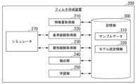
- FIG. 1 is a configuration diagram of a filter creating device.
- 3A to 3C are diagrams each showing a schematic diagram of each of the feature amounts.
- 11 is a diagram for explaining a difference between a reference path and an individual path.
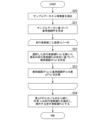
- FIG. 10 is a flowchart showing an example of a process flow of a filter creating device.
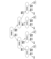
- FIG. 1 is a diagram illustrating the contents of a trained model.
- the filter according to the present invention is applied to a control device of a moving body that controls a driving device of the moving body to move the moving body.
- the moving body is, for example, an object that moves autonomously while leading a leading object in an area where pedestrians walk. Alternatively, the moving body may move alone, or may follow a following object at a certain distance. In the following description, the moving body is assumed to lead a leading object.
- the area where pedestrians walk is a sidewalk, a public open space, a floor in a building, etc., and may include a roadway.
- the leading object is, for example, one of the pedestrians, but may also be a robot or an animal (hereinafter, this is referred to as user U).
- the moving body moves a little ahead of an elderly user U while heading toward a predetermined destination point, so that other pedestrians who hinder the movement of the user U do not get too close to the user U (that is, it operates to make a way for the user U).
- the user U is not limited to elderly people, but may be people who tend to have difficulty walking, children, people shopping at a supermarket, patients moving around in a hospital, pets taking a walk, etc.
- Such actions may not be performed all the time, but may be performed temporarily.
- a moving object runs alongside or pursues a user and detects a predetermined situation (e.g., the presence of an obstacle or traffic congestion) in the user's direction of travel, the moving object may temporarily lead the user by executing a predetermined algorithm.
- a predetermined situation e.g., the presence of an obstacle or traffic congestion
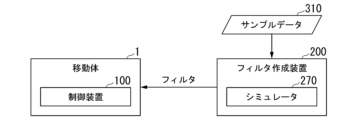
- [Overall configuration] 1 is a diagram showing an example of the relationship between a moving body 1 and a filter creation device 200.
- the filter creation device 200 includes, for example, a simulator 270 that simulates the functions of a control device 100 (described later) of the moving body 1. Alternatively, the filter device 200 may use an actual moving body 1 in place of the simulator 270.
- the filter creation device 200 acquires sample data 310, which is data on a plurality of pedestrians, and creates a filter to be used by the moving body 1 based on the sample data 310.
- the created filter (filter program) is installed in the moving body 1. Below, the moving body 1 will be described first, and then the filter creation device 200 will be described.
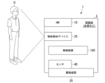
- [Mobile configuration] 2 is a configuration diagram of the moving body 1.
- the moving body 1 is equipped with, for example, an HMI (Human Machine Interface) 10, an object detection device 20, a driving device 30, a sensor 40, and a control device 100. These components are supported or housed by a base 5.
- HMI Human Machine Interface
- the HMI 10 presents various information to the user U and accepts input operations by the user U.
- the HMI 10 includes various display devices, speakers, buzzers, touch panels, switches, keys, short-range wireless communication devices, etc.
- the HMI 10 accepts the setting of a destination point.
- the object detection device 20 is a device that generates data for recognizing other pedestrians and the user U present around the moving body 1.
- the object detection device 20 includes, for example, a camera whose shooting range is the area around the moving body 1.
- the object detection device 20 may also include sensors such as a radar device, a LIDAR (Light Detection and Ranging) sensor, and an ultrasonic sensor, as well as an object recognition device that identifies objects by performing sensor fusion processing based on the output of these sensors.
- sensors such as a radar device, a LIDAR (Light Detection and Ranging) sensor, and an ultrasonic sensor, as well as an object recognition device that identifies objects by performing sensor fusion processing based on the output of these sensors.
- LIDAR Light Detection and Ranging
- the driving device 30 is a mechanism for moving the moving body 1 including the base body 5 in any direction.
- the driving device 30 includes, for example, a plurality of wheels, a driving motor attached to one or more of the wheels, and a steering device attached to one or more of the wheels.
- the driving device 30 moves the moving body 1 while keeping the front surface of the base body 5 facing the traveling direction of the moving body 1.
- Sensor 40 is a sensor for detecting the behavior of moving body 1.
- Sensor 40 includes, for example, a wheel speed sensor for detecting the wheel speed, an acceleration sensor for detecting the acceleration acting on moving body 1, a yaw rate sensor attached near the center of gravity in the horizontal direction of base body 5, a steering angle sensor for detecting the steering angle of the steered wheels (steered wheels), and an orientation sensor for detecting the horizontal orientation of moving body 1.
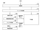
- FIG. 3 is a configuration diagram of the control device 100.
- the control device 100 includes, for example, a recognition unit 110, a filter processing unit 115, a path generation unit 120, a prediction unit 130, and a drive control unit 140.
- the path generation unit 120 includes a path candidate setting unit 122 and a score calculation unit 124.
- These components are realized, for example, by a hardware processor such as a CPU (Central Processing Unit) executing a program (software). Some or all of these components may be realized by hardware (including circuitry) such as an LSI (Large Scale Integration), an ASIC (Application Specific Integrated Circuit), an FPGA (Field-Programmable Gate Array), or a GPU (Graphics Processing Unit), or may be realized by collaboration between software and hardware.
- LSI Large Scale Integration
- ASIC Application Specific Integrated Circuit
- FPGA Field-Programmable Gate Array
- GPU Graphics Processing Unit
- the program may be stored in advance in a storage device (a storage device with a non-transient storage medium) such as a hard disk drive (HDD) or flash memory, or may be stored in a removable storage medium (non-transient storage medium) such as a DVD or CD-ROM, and installed in the storage device by inserting the storage medium into a drive device.
- a storage device a storage device with a non-transient storage medium
- HDD hard disk drive
- flash memory or may be stored in a removable storage medium (non-transient storage medium) such as a DVD or CD-ROM, and installed in the storage device by inserting the storage medium into a drive device.
- the recognition unit 110 recognizes objects including other pedestrians (hereinafter simply referred to as pedestrian P) and user U based on the data output by the object detection device 20.
- pedestrian P pedestrians
- the recognition unit 110 recognizes pedestrians by inputting camera images into a trained model for identifying pedestrians. The same applies to objects other than pedestrians.
- the recognition unit 110 may store multiple images of user U captured in advance by a camera as templates in a storage unit (not shown), and identify user U by comparing the templates with the camera images.
- the recognition unit 110 may recognize the position of user U by using communication directivity to perform short-range wireless communication between the terminal device held by user U and the HMI 10.
- the filter processing unit 115 extracts one or more pedestrians P to be monitored (used as a basis for determining whether to control the moving body 1) from among the multiple pedestrians P.
- the filter processing unit 115 operates according to a filter (filter program) created by the filter creation device 200.
- the filter processing unit 115 is an example of a "filter device.”
- a pedestrian P before processing by the filter processing unit 115 is referred to as a pedestrian candidate Pc
- a pedestrian P extracted by the filter processing unit 115 is referred to as a pedestrian P.
- the filter processing unit 115 derives multiple feature amounts for each pedestrian candidate Pc based on the recognition result of the recognition unit 110.
- the content of the feature amounts is the same as that described in the description of the filter creation device 200 below.
- a pedestrian candidate Pc that has not been excluded by the filter processing unit 115 is treated as a pedestrian P from now on.
- the route candidate setting unit 122 of the route generating unit 120 generates a plurality of route candidates Pmc(i) that are candidates for the route Rm along which the moving body 1 should move in the future.
- i is an identifier of the route candidate and takes a value from 1 to n (n is a natural number of 2 or more).
- the route and route candidates are generated as a series of a plurality of (q) route points arranged at a predetermined distance.
- the route points represent the points to be reached by the moving body 1 at each predetermined time (each step).
- the route candidate setting unit 122 generates route candidates Rmc(1), Rmc(2), Rmc(4), and Rmc(5) so as to spread out to the left and right, centered on the route candidate Rmc(3) that extends linearly along the front direction Dm of the moving body 1.
- the interval between the route points is, for example, constant, and each route candidate has a length of q steps.
- the route candidates are not generated so as to reach the destination point given to the moving body 1, but are generated so as to have a length of a certain distance x q steps.
- the route candidate Rmc(2) is generated so as to turn left by a predetermined angle in each step.
- the route candidate Rmc(1) is generated so as to turn left by a larger predetermined angle in each step.
- route candidates Rmc(4) and Rmc(5) The opposite is true for the route candidates Rmc(4) and Rmc(5).
- the above rule is merely an example, and route candidates may be generated based on other rules as long as they show a similar tendency (gradual spread).
- the route candidate setting unit 122 outputs the route candidate Rmc(i) to the prediction unit 130.
- the distance between route points is a fixed distance, but the distance may be variable.
- a long distance means that the route moves at a relatively high speed
- a short distance means that the route moves at a relatively low speed.
- the route Rm and route candidates Rmc(i) may include an element of speed.
- the route candidate setting unit 122 generates derivative route candidates with varying speeds based on route candidates generated with a fixed distance between route points.
- the prediction unit 130 predicts the future positions of the pedestrian P and the user U for each route candidate Rmc(i) based on the route candidate Rmc(i).
- the prediction unit 130 predicts the future positions of the pedestrian P and the user U by, for example, any of the methods described in Non-Patent Documents 1 to 3, or a combination of these methods.
- FIG. 5 is a flowchart showing an example of the processing contents of the prediction unit 130 for pedestrian P.
- the prediction unit 130 performs goal prediction for each pedestrian P (S1). For example, the prediction unit 130 observes the movement trajectory of the pedestrian P in time series, and predicts that the goal (destination point) of the pedestrian P is the destination of the movement vector of the pedestrian P in a state where there are no other pedestrians P, moving body 1, or user U in the vicinity.
- the prediction unit 130 performs the processes of S2 to S6 for each route candidate Rmc(i).
- the prediction unit 130 inputs the route candidates Rmc(i) of the moving body 1 one by one in sequence (S2), and generates an ideal route Ru#(i) for the user U to follow the moving body 1 in association with each of the route candidates Rmc(i) (S3).
- the ideal route Ru#(i) is a route along which the user U is expected to travel, assuming that no pedestrian P is present in the vicinity of the moving body 1 and the user U.
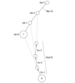
- FIG. 6 is a diagram for explaining an example of a method for generating an ideal route Ru#(i). Here, an example is shown of generating an ideal route Ru#(5) corresponding to the route candidate Rmc(5).
- the prediction unit 130 generates the ideal route Ru#(5) for the user U so that the movement vector Vu-1 of the user U moving from step 0 (the time of calculation) to step 1 points toward the position Om-0 of the moving body 1 at step 0, the movement vector Vu-2 of the user U moving from step 1 to step 2 points toward the position Om-1 of the moving body 1 at step 1, and the movement vector Vu-3 of the user U moving from step 2 to step 3 points toward the position Om-2 of the moving body 1 at step 2, that is, so that the user U follows the moving body 1 with a one-step delay.
- This generation method is merely an example, and other generation methods may be adopted.
- the virtual forces include, for example, (1) an influence F1 caused by the approach of other objects (here, the moving body 1 and the user U), (2) a turning force F2 that corrects direction toward the goal after changing course mainly due to the influence F1, and (3) an acceleration/deceleration force F3 that adjusts speed to return to the desired speed after accelerating or decelerating mainly due to the influence F1.
- F1 is a translational force acting in any direction on a two-dimensional plane
- F2 is a rotational force centered on the pedestrian
- F3 is a translational force parallel to the movement vector of the pedestrian.
- F1 to F3 are expressed, for example, simply as follows.
- integral elements, differential elements, etc. may be added to calculate the virtual forces.
- F1 (weight) x (coefficient) x (relative speed) / (distance to other objects)
- F2 (moment of inertia) x (coefficient) x (angle difference between the most recent movement vector and the direction toward the goal)
- F3 weight x (coefficient) x (difference between desired speed and current speed)
- the prediction unit 130 predicts the position and speed of pedestrian P(k) one step ahead, assuming that a virtual force continues to act for one step (S5). By executing this process for q steps for each pedestrian, a predicted route Rp(k,i) for each pedestrian P(k) is generated and output (S6). This predicted route Rp(k,i) is the result of predicting the future position of each pedestrian P(k) for each route candidate Rmc(i).
- FIG. 7 is a flowchart showing an example of the processing contents of the prediction unit 130 regarding the user U.
- the prediction unit 130 performs the processes of S11 to S14 for each route candidate Rmc(i).
- the prediction unit 130 inputs the predicted route of each pedestrian corresponding to the route candidate Rmc(i) (S11).
- the prediction unit 130 executes the processes of S12 and S13 for q steps.
- the prediction unit 130 calculates various forces acting on the user U in the current step, assuming that the moving body 1 and each pedestrian P(k) move according to the route candidate Rmc(i) and the predicted route Rp(k,i) of each pedestrian (S12).
- the method of calculating the various forces may be the same as the process of S4 in FIG. 5.
- the prediction unit 130 predicts the position and speed of the user U one step ahead, assuming that a virtual force continues to act for one step (S13).
- the prediction unit 130 By executing the process for q steps, the prediction unit 130 generates and outputs a predicted route Ru(i) of the user U for each route candidate Rmc(i) (S14). This predicted route Ru(i) is the result of predicting the future location of user U for each route candidate Rmc(i).
- the total score SC(i) is expressed by formula (1). ⁇ and ⁇ are coefficients, SC1(i) is the first score, and SC2(i) is the second score. The smaller the total score SC(i), the better the evaluation, and the coefficients ⁇ , ⁇ , and ⁇ and ⁇ described later are positive values.
- the first score SC1(i) is a score based on the positional relationship between the moving body 1 and the destination point assigned to the moving body 1. For example, the first score SC1(i) is calculated so that the longer the distance X1 between the end point of the route candidate Rmc(i) (the point farthest from the moving body 1) and the destination point assigned to the moving body 1, the larger the first score SC1(i) is, and the shorter the distance X1 is, the smaller the first score SC1(i) is.
- the first score SC1(i) may use the distance X1 as is, or may be the logarithm or exponent of the distance X1, or may be the output value of some function that uses the distance as an input value.
- the second score SC2(i) is a score based on the positional relationship between the user U and the pedestrian P from the present to a future time (the time when the end of the route is reached).
- the second score SC2(i) has a more positive value the longer the distance between the user U and the pedestrian P is maintained.
- the second score SC2(i) is calculated based on formula (2).
- SC3(i) is the third score, and SC4(i) is the fourth score.
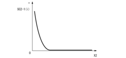
- the third score SC3(i) is calculated by calculating the distance between the route points of the predicted route Ru(i) of the user U and the route points of the predicted routes Rp(k, i) of all the pedestrians P for each step, and the shorter the shortest distance X2 (i.e., the distance when the user U and any pedestrian P are closest to each other in q steps) is, the larger the third score SC3(i) is calculated, and the longer the distance is, the smaller the third score SC3(i) is calculated.
- the third score SC3(i) may indicate a constant value.
- the third score SC3(i) may indicate zero.
- FIG. 8 is a diagram showing an example of the characteristics of the third score SC3(i). It is preferable that the third score SC3(i) is calculated to rapidly increase as the distance X2 decreases in order to prevent the user U and the pedestrian P from approaching each other.
- a barrier function or an exponential function is preferably used, but it is not limited to these and any function showing a similar tendency may be used.
- the fourth score SC4(i) is calculated so that it becomes larger as the degree of deviation between the predicted route Ru(i) and the ideal route Ru#(i) becomes larger.
- the score calculation unit 124 squares the distance between each of the route points of the predicted route Ru(i) and the ideal route Ru#(i) for each step, and calculates the square of the sum as the fourth score SC4(i).
- FIG. 9 is a diagram for explaining the calculation process of the fourth score SC4(i).
- r1 is the distance between the route points of the first step of each of the predicted route Ru(i) and the ideal route Ru#(i)
- r2 is the distance between the route points of the second step of each of the predicted route Ru(i) and the ideal route Ru#(i)
- r3 is the distance between the route points of the third step of each of the predicted route Ru(i) and the ideal route Ru#(i).
- the fourth score SC4(i) is calculated, for example, as ⁇ (r1 2 +r2 2 +r3 2 ).
- the score calculation unit 124 calculates the total score SC(i) for each route candidate Rmc(i), then selects the route candidate Rmc(i) with the smallest total score SC(i) and outputs it to the drive control unit 140 as the route Rm of the moving body 1.
- the drive control unit 140 controls the drive unit 30 attached to the moving body 1 so that the moving body 1 moves along the route Rm.
- the moving body 1 is controlled to simultaneously lead (guide) the user U to the given destination by heading towards the destination, and to prevent other pedestrians P from getting too close to the user U due to its own presence. For example, in a scene where a pedestrian P is approaching the user U, the total score of a route candidate Rmc(i) in which the moving body 1 gets between the pedestrian P and the user U to prevent the pedestrian P from approaching should be relatively high.
- FIG. 10 and 11 are diagrams illustrating an example of a situation in which the moving body 1 suppresses the approach of the user U and the pedestrian P.
- the right diagram shows the moving path of the pedestrian P when the coefficient ⁇ is sufficiently larger than 0.
- the moving body 1 takes the route Rm that bulges to the right, and (by the influence F1) causes the pedestrian P to take a route to the left, thereby suppressing the approach of the pedestrian P to the user U.
- the moving body 1 deliberately moves at a low speed, and (by the influence F1) causes the pedestrian P to take a route to the right, thereby suppressing the approach of the pedestrian P to the user U.
- the control device 100 can generate a route for the moving body 1 to behave appropriately for the user U.
- Each of the coefficients ⁇ , ⁇ , ⁇ , and ⁇ may be a fixed value or may be arbitrarily adjusted.
- control device 100 is described as being mounted on the moving body 1, but this is not limited thereto.
- the control device 100 may be installed at a location away from the moving body 1, acquire output data from the object detection device 20 via communication, and transmit a drive instruction signal to the drive device 30, i.e., remotely control the moving body 1.
- [Create Filter] 12 is a configuration diagram of the filter creation device 200.
- the filter creation device 200 includes, for example, a feature acquisition unit 210, a reference path acquisition unit 220, an individual path acquisition unit 230, an extraction unit 240, a learning unit 250, a simulator 270, and a storage unit 300.
- the components other than the storage unit 300 are realized by, for example, a hardware processor such as a CPU executing a program (software). Some or all of these components may be realized by hardware (including circuitry) such as an LSI, ASIC, FPGA, or GPU, or may be realized by cooperation between software and hardware.
- the program may be stored in advance in a storage device such as an HDD or flash memory (a storage device having a non-transient storage medium), or may be stored in a removable storage medium such as a DVD or CD-ROM (a non-transient storage medium), and may be installed in the storage device by mounting the storage medium in a drive device.
- a storage device such as an HDD or flash memory (a storage device having a non-transient storage medium)
- a removable storage medium such as a DVD or CD-ROM (a non-transient storage medium)
- the storage unit 300 is a RAM (Random Access Memory), a flash memory, a HDD, etc.
- the storage unit 300 stores information such as sample data 310 and model setting information 320.
- the sample data 310 is, for example, time series data such as the relative position, speed, and acceleration of a pedestrian as viewed from the moving body 1, and the position of a user U as viewed from the moving body 1.
- the sample data 310 may be time series data on an absolute coordinate system.
- the sample data 310 may be data acquired when the moving body 1 is moved in a real environment, or may be virtual data created based on a probabilistic calculation.
- the pedestrian P included in the sample data 310 is referred to as a pedestrian candidate Pc.
- the model setting information 320 is information that specifies the type of machine learning model that is the basis of the trained model that functions as a filter program, the number of layers, node connection information, etc.
- the feature amount acquiring unit 210 derives a plurality of feature amounts from the sample data.
- the plurality of feature amounts are, for example, as follows. Some of the feature amounts may be derived by causing the simulator 270 to perform a simulation.
- Fig. 13 is a diagram showing each of the feature amounts described below. Due to space limitations, the pedestrian candidates Pc are divided appropriately for each feature amount. (1) The average value of the minimum distance Dmin between the pedestrian candidate Pc and k other pedestrian candidates Pc (two in the figure) in the order of their positions in a given observation period. (2) The speed V of the pedestrian candidate Pc.
- the reference path acquisition unit 220 acquires a reference path, which is a path of the moving body 1 generated by the function of the control device 1 based on the presence of multiple pedestrian candidates Pc.
- the reference path acquisition unit 220 acquires the reference path by providing sample data 310 to the simulator 270.
- the simulator 270 is a device (e.g., a virtual machine or a physical processor) that has a path generation function equivalent to that of the control device 100 described above.
- the individual route acquisition unit 230 selects pedestrian candidates Pc one by one from the sample data 310, and acquires, for each pedestrian candidate Pc, an individual route, which is the route of the moving body 1 generated by the function of the control device 1, based on the existence of the remaining pedestrian candidates Pc excluding the selected pedestrian candidates Pc.
- the reference route acquisition unit 220 acquires an individual route by providing the simulator 270 with data from the sample data 310 excluding the pedestrian candidates Pc one by one.
- the extraction unit 240 extracts individual routes whose difference from the reference route is smaller than other individual routes. For example, the extraction unit 240 extracts (N-M) pedestrian candidates Pc from the number N of pedestrian candidates Pc in order of decreasing difference from the reference route compared to other individual routes, so that M pedestrian candidates Pc remain.
- the "difference from the reference route" is, for example, a value obtained by calculating the RMSD (root mean square deviation) of the difference in position at each step when the reference route and an individual route are divided into a finite number of steps.
- Figure 14 is a diagram for explaining the difference between the reference route and an individual route. In the diagram, RP is the reference route, IP is the individual route, and ⁇ Y is the difference in position at some steps.
- FIG. 15 is a flowchart showing an example of the process flow of the filter creation device 200 described above.
- the feature acquisition unit 210 derives a number of feature amounts for each of a number of pedestrian candidates Pc from the sample data 310 (S20).
- the reference path acquisition unit 220 generates a reference path using the simulator 270 (S21).
- the individual route acquisition unit 230 and the extraction unit 240 execute the processes of S22 and S23 for each pedestrian candidate Pc(u) included in the sample data 310.
- the individual route acquisition unit 230 uses the simulator 270 to generate an individual route IP(u) based on the existence of the remaining pedestrian candidates Pc excluding the selected pedestrian candidate Pc(u) (S22).
- the extraction unit 240 calculates the difference ⁇ P(u) between the individual route IP(u) and the reference route RP (S23).
- the extraction unit 240 extracts N-M pedestrian candidates Pc in ascending order of difference ⁇ P, and sets them as pedestrian candidates to be excluded (S24).
- the learning unit 250 generates a trained model that functions as a filter by machine learning.
- the learning unit 250 sets the feature amount of the pedestrian candidate Pc (hereinafter referred to as pedestrian candidate Pc(p)) extracted by the extraction unit 240 as positive example training data, and the feature amount of the pedestrian candidate Pc (hereinafter referred to as pedestrian candidate Pc(n)) that was not extracted as negative example training data.
- the learning unit 250 then generates a trained model by machine learning so that when the feature amount of the pedestrian candidate Pc(p) is input, information indicating that the pedestrian is a pedestrian to be excluded (for example, the probability that the pedestrian should be excluded, or a flag indicating that the pedestrian is a pedestrian to be excluded) is output, and when the feature amount of the pedestrian candidate Pc(n) is input, information indicating that the pedestrian is not a pedestrian to be excluded is output.
- the trained model is, for example, a random forest.
- FIG. 16 is a diagram showing a schematic example of the contents of a trained model.
- the trained model may be in the form of a DNN (Deep Neural Network) or the like.
- the trained model is not limited to one that outputs, when the feature values of a single pedestrian candidate Pc are input, information indicating that the pedestrian candidate is a pedestrian to be excluded, but may also output, when the feature values of multiple pedestrian candidates Pc are input, information indicating which pedestrian candidates Pc are pedestrians to be excluded.
- the trained model may be created so that the criteria (threshold value, etc.) for determining whether or not each pedestrian candidate Pc is to be excluded varies depending on the number of pedestrian candidates Pc whose feature values are input.
- the feature amount is set to a fixed value, but it may be narrowed down from a larger number of feature amounts prepared in advance.
- the distance between the pedestrian candidate Pc and the moving body 1 (9) the distance between the pedestrian candidate Pc and the user U, (10) the distance between the pedestrian candidate Pc and the destination, (11) the angle between the direction of the pedestrian candidate Pc and the line connecting the user U and the moving body 1, (12) the vibration amount of the direction of the pedestrian candidate Pc, (13) the distance between the future position of the pedestrian candidate Pc and the moving body 1, and the like may be prepared in advance.
- the filter creation device 200 may create a learned model by excluding feature amounts one by one, similar to narrowing down the pedestrian candidates Pc, and sequentially exclude feature amounts corresponding to a learned model in which the pedestrian candidate Pc to be excluded is not significantly different from other learned models.
- the embodiment described above can assist the control device in appropriately narrowing down the pedestrians to be monitored.
- a filter creation device for creating a filter comprising: the filter is a filter used by a control device that controls a moving object that autonomously moves in an area where pedestrians walk, the control device recognizing objects including the pedestrians and generating a future route for the moving object based on the recognition result, to narrow down pedestrians to be monitored; one or more storage media storing computer-readable instructions; a processor coupled to the one or more storage media; The processor executes the computer-readable instructions to: Acquiring a plurality of feature amounts of a plurality of sample pedestrians; acquiring a reference route, which is a route of the moving object generated by a function of the control device based on the presence of the plurality of pedestrians; acquiring an individual route that is a route of the moving object generated by a function of the control device based on the presence of a group of pedestrians obtained by removing one pedestrian from the plurality of pedestrians; extracting an individual path having a smaller difference from the reference path than other individual paths; Extracting
Landscapes
- Engineering & Computer Science (AREA)
- Aviation & Aerospace Engineering (AREA)
- Radar, Positioning & Navigation (AREA)
- Remote Sensing (AREA)
- Physics & Mathematics (AREA)
- General Physics & Mathematics (AREA)
- Automation & Control Theory (AREA)
- Traffic Control Systems (AREA)
Abstract
サンプルとなる複数の歩行者の複数の特徴量を取得することと、前記複数の歩行者の存在に基づいて前記制御装置の機能によって生成される前記移動体の経路である基準経路を取得することと、前記複数の歩行者から一人ずつ除いた歩行者群の存在に基づいて前記制御装置の機能によって生成される前記移動体の経路である個別経路を取得することと、前記基準経路との差が他の個別経路に比して小さい個別経路を抽出することと、抽出した個別経路に対応する歩行者を抽出することと、前記抽出した歩行者の特徴量が学習済モデルに入力されると除外対象の歩行者であることを示す情報が出力されるように、機械学習によって前記学習済モデルを生成することと、を備える、フィルタ作成方法。
Description
本発明は、フィルタ作成方法、フィルタ作成装置、プログラム、およびフィルタ装置に関する。
近年、利用者の荷物を運搬する等の目的で、利用者に追従して自律的に移動する移動体(ロボット、マイクロモビリティなどと称される)について実用化が進められている。マイクロモビリティに関する走行制御装置の発明が開示されている(特許文献1)。また、利用者に追従するだけでなく、利用者を先導して自律的に移動する移動体についても研究が進められている。
上記の移動体は歩行者が存在する領域(フロア、歩道、空き地など)を移動する場合がある。車道を移動する車両とは異なり、歩行者が多数存在する中を移動体が移動する場合、多くの歩行者を接触回避対象として監視しなければならず、制御装置の処理負荷が過大になることがあり得る。このため、監視対象の歩行者を絞り込むことが望ましいが、従来の技術では監視対象の歩行者の絞り込みについて十分に検討されていなかった。
本発明は、このような事情を考慮してなされたものであり、監視対象の歩行者を適切に絞り込むように制御装置を支援することができるフィルタ作成方法、フィルタ作成装置、プログラム、およびフィルタ装置を提供することを目的の一つとする。
この発明に係るフィルタ作成方法、フィルタ作成装置、プログラム、およびフィルタ装置は、以下の構成を採用した。
(1):この発明の一態様に係るフィルタ作成方法は、フィルタ作成装置がフィルタを作成するフィルタ作成方法であって、前記フィルタは、歩行者が歩行する領域を自律的に移動する移動体を制御する制御装置であって、前記歩行者を含む物体を認識し、認識結果に基づいて前記移動体が将来進むべき経路を生成する制御装置が、監視対象の歩行者を絞り込むためのフィルタであり、前記フィルタ作成方法は、サンプルとなる複数の歩行者の複数の特徴量を取得することと、前記複数の歩行者の存在に基づいて前記制御装置の機能によって生成される前記移動体の経路である基準経路を取得することと、前記複数の歩行者から一人ずつ除いた歩行者群の存在に基づいて前記制御装置の機能によって生成される前記移動体の経路である個別経路を取得することと、前記基準経路との差が他の個別経路に比して小さい個別経路を抽出することと、抽出した個別経路に対応する歩行者を抽出することと、前記抽出した歩行者の特徴量が学習済モデルに入力されると除外対象の歩行者であることを示す情報が出力されるように、機械学習によって前記学習済モデルを生成することと、を備えるものである。
(1):この発明の一態様に係るフィルタ作成方法は、フィルタ作成装置がフィルタを作成するフィルタ作成方法であって、前記フィルタは、歩行者が歩行する領域を自律的に移動する移動体を制御する制御装置であって、前記歩行者を含む物体を認識し、認識結果に基づいて前記移動体が将来進むべき経路を生成する制御装置が、監視対象の歩行者を絞り込むためのフィルタであり、前記フィルタ作成方法は、サンプルとなる複数の歩行者の複数の特徴量を取得することと、前記複数の歩行者の存在に基づいて前記制御装置の機能によって生成される前記移動体の経路である基準経路を取得することと、前記複数の歩行者から一人ずつ除いた歩行者群の存在に基づいて前記制御装置の機能によって生成される前記移動体の経路である個別経路を取得することと、前記基準経路との差が他の個別経路に比して小さい個別経路を抽出することと、抽出した個別経路に対応する歩行者を抽出することと、前記抽出した歩行者の特徴量が学習済モデルに入力されると除外対象の歩行者であることを示す情報が出力されるように、機械学習によって前記学習済モデルを生成することと、を備えるものである。
(2):上記(1)の態様において、前記複数の特徴量は、着目する歩行者に位置が近い順に所定人数の他の歩行者と、前記着目する歩行者との間の、所定の観測期間における最小距離の平均値を含むものである。
(3):上記(1)の態様において、前記複数の特徴量は、前記歩行者の速度を含むものである。
(4):上記(1)の態様において、前記制御装置は、前記移動体が先導対象者を先導しながら移動する経路を生成するものであり、前記複数の特徴量は、前記移動体と前記先導対象者を結ぶ直線から前記歩行者までの距離を含むものである。
(5):上記(1)の態様において、前記複数の特徴量は、前記歩行者が監視対象領域にいる時間の長さを含むものである。
(6):上記(1)の態様において、前記複数の特徴量は、前記移動体から見た前記歩行者の方位を含むものである。
(7):上記(1)の態様において、前記複数の特徴量は、前記移動体を基準とした座標系における前記歩行者の向きを含むものである。
(8):本発明の他の態様に係るフィルタ作成装置は、フィルタを作成するフィルタ作成装置であって、前記フィルタは、歩行者が歩行する領域を自律的に移動する移動体を制御する制御装置であって、前記歩行者を含む物体を認識し、認識結果に基づいて前記移動体が将来進むべき経路を生成する制御装置が、監視対象の歩行者を絞り込むためのフィルタであり、サンプルとなる複数の歩行者の複数の特徴量を取得する特徴量取得部と、前記複数の歩行者の存在に基づいて前記制御装置の機能によって生成される前記移動体の経路である基準経路を取得する基準経路取得部と、前記複数の歩行者から一人ずつ除いた歩行者群の存在に基づいて前記制御装置の機能によって生成される前記移動体の経路である個別経路を取得する個別経路取得部と、前記基準経路との差が他の個別経路に比して小さい個別経路を抽出し、抽出した前記個別経路に対応する前記歩行者を抽出する抽出部と、抽出された前記歩行者の特徴量が学習済モデルに入力されると除外対象の歩行者であることを示す情報が出力されるように、機械学習によって前記学習済モデルを生成する学習部と、を備えるものである。
(9):本発明の他の態様に係るプログラムは、フィルタを作成するフィルタ作成装置に実行させるプログラムであって、前記フィルタは、歩行者が歩行する領域を自律的に移動する移動体を制御する制御装置であって、前記歩行者を含む物体を認識し、認識結果に基づいて前記移動体が将来進むべき経路を生成する制御装置が、監視対象の歩行者を絞り込むためのフィルタであり、前記フィルタ作成装置に、サンプルとなる複数の歩行者の複数の特徴量を取得することと、前記複数の歩行者の存在に基づいて前記制御装置の機能によって生成される前記移動体の経路である基準経路を取得することと、前記複数の歩行者から一人ずつ除いた歩行者群の存在に基づいて前記制御装置の機能によって生成される前記移動体の経路である個別経路を取得することと、前記基準経路との差が他の個別経路に比して小さい個別経路を抽出することと、抽出した個別経路に対応する歩行者を抽出することと、前記抽出した歩行者の特徴量が学習済モデルに入力されると除外対象の歩行者であることを示す情報が出力されるように、機械学習によって前記学習済モデルを生成することと、を実行させるためのプログラムである。
(10):本発明の他の態様に係るフィルタ装置は、歩行者が歩行する領域を自律的に移動する移動体を制御する制御装置であって、前記歩行者を含む物体を認識し、認識結果に基づいて前記移動体が将来進むべき経路を生成する制御装置に適用されるフィルタ装置であって、フィルタ作成装置が、サンプルとなる複数の歩行者の複数の特徴量を取得することと、前記複数の歩行者の存在に基づいて前記制御装置の機能によって生成される前記移動体の経路である基準経路を取得することと、前記複数の歩行者から一人ずつ除いた歩行者群の存在に基づいて前記制御装置の機能によって生成される前記移動体の経路である個別経路を取得することと、前記基準経路との差が他の個別経路に比して小さい個別経路を抽出することと、抽出した個別経路に対応する歩行者を抽出することと、前記抽出した歩行者の特徴量が学習済モデルに入力されると除外対象の歩行者であることを示す情報が出力されるように、機械学習によって前記学習済モデルを生成することと、を実行することにより生成されたフィルタを用いて、前記制御装置が監視対象とする歩行者を絞り込むものである。
(1)~(10)の態様によれば、監視対象の歩行者を適切に絞り込むように制御装置を支援することができる。
[概要]
以下、図面を参照し、本発明のフィルタ作成方法、フィルタ作成装置、プログラム、およびフィルタ装置の実施形態について説明する。本発明に係るフィルタは、移動体の駆動装置を制御して移動体を移動させる移動体の制御装置に適用されるものである。移動体とは、例えば、歩行者が歩行する領域を、先導対象者を先導しながら自律的に移動するものである。これに代えて、移動体は単体で移動するものであってもよいし、追従対象者にある程度の距離をとって追従するものであってもよい。以下の説明では、移動体は先導対象者を先導するものとする。歩行者が歩行する領域とは、歩道、公開空地、建物内のフロアなどであり、車道を含んでもよい。以下の説明では移動体には人が搭乗しないものとするが、移動体に人が搭乗しても構わない。先導対象者は、例えば歩行者の一人であるが、ロボットや動物であってもよい(以下、これをユーザUと称する)。移動体は、例えば、予め与えられた目的地点に向かいつつ、高齢者であるユーザUの少し先を移動することで、ユーザUの移動の妨げになる他の歩行者がユーザUに近づき過ぎないように動作する(つまり、ユーザUに道をつくるように動作する)。ユーザUは、高齢者に限らず、歩行が困難な傾向にある人、子供、スーパーで買い物をする人、病院内を移動する患者、散歩をするペットなどであってもよい。なお、このような動作は常時行われるのではなく、一時的に行われてもよい。例えば、移動体がユーザと並走、又はユーザを追走し、ユーザの進行方向上に所定の状況(例えば、障害物の存在や交通状況の混雑など)を検知した場合に、移動体が、所定のアルゴリズムを実行することにより、一時的にユーザを先導してもよい。
以下、図面を参照し、本発明のフィルタ作成方法、フィルタ作成装置、プログラム、およびフィルタ装置の実施形態について説明する。本発明に係るフィルタは、移動体の駆動装置を制御して移動体を移動させる移動体の制御装置に適用されるものである。移動体とは、例えば、歩行者が歩行する領域を、先導対象者を先導しながら自律的に移動するものである。これに代えて、移動体は単体で移動するものであってもよいし、追従対象者にある程度の距離をとって追従するものであってもよい。以下の説明では、移動体は先導対象者を先導するものとする。歩行者が歩行する領域とは、歩道、公開空地、建物内のフロアなどであり、車道を含んでもよい。以下の説明では移動体には人が搭乗しないものとするが、移動体に人が搭乗しても構わない。先導対象者は、例えば歩行者の一人であるが、ロボットや動物であってもよい(以下、これをユーザUと称する)。移動体は、例えば、予め与えられた目的地点に向かいつつ、高齢者であるユーザUの少し先を移動することで、ユーザUの移動の妨げになる他の歩行者がユーザUに近づき過ぎないように動作する(つまり、ユーザUに道をつくるように動作する)。ユーザUは、高齢者に限らず、歩行が困難な傾向にある人、子供、スーパーで買い物をする人、病院内を移動する患者、散歩をするペットなどであってもよい。なお、このような動作は常時行われるのではなく、一時的に行われてもよい。例えば、移動体がユーザと並走、又はユーザを追走し、ユーザの進行方向上に所定の状況(例えば、障害物の存在や交通状況の混雑など)を検知した場合に、移動体が、所定のアルゴリズムを実行することにより、一時的にユーザを先導してもよい。
[全体構成]
図1は、移動体1とフィルタ作成装置200との関係の一例を示す図である。フィルタ作成装置200は、例えば、移動体1の制御装置100(後述)の機能を模擬したシミュレータ270を備える。これに代えて、フィルタ装置200は、移動体1の実機をシミュレータ270代わりに使用してもよい。フィルタ作成装置200は、複数の歩行者のデータであるサンプルデータ310を取得し、それに基づいて移動体1が使用するフィルタを作成する。作成されたフィルタ(フィルタプログラム)は移動体1に搭載される。以下、まず移動体1について説明した後に、フィルタ作成装置200について説明する。
図1は、移動体1とフィルタ作成装置200との関係の一例を示す図である。フィルタ作成装置200は、例えば、移動体1の制御装置100(後述)の機能を模擬したシミュレータ270を備える。これに代えて、フィルタ装置200は、移動体1の実機をシミュレータ270代わりに使用してもよい。フィルタ作成装置200は、複数の歩行者のデータであるサンプルデータ310を取得し、それに基づいて移動体1が使用するフィルタを作成する。作成されたフィルタ(フィルタプログラム)は移動体1に搭載される。以下、まず移動体1について説明した後に、フィルタ作成装置200について説明する。
[移動体の構成]
図2は、移動体1の構成図である。移動体1には、例えば、HMI(Human machine Interface)10と、物体検知デバイス20と、駆動装置30と、センサ40と、制御装置100とが搭載される。これらの構成は、基体5によって支持或いは収容されている。
図2は、移動体1の構成図である。移動体1には、例えば、HMI(Human machine Interface)10と、物体検知デバイス20と、駆動装置30と、センサ40と、制御装置100とが搭載される。これらの構成は、基体5によって支持或いは収容されている。
HMI10は、ユーザUに対して各種情報を提示すると共に、ユーザUによる入力操作を受け付ける。HMI10は、各種表示装置、スピーカ、ブザー、タッチパネル、スイッチ、キー、近距離無線通信装置などを含む。例えば、HMI10は、目的地点の設定を受け付ける。
物体検知デバイス20は、移動体1の周囲に存在する他の歩行者およびユーザUを認識するためのデータを生成するデバイスである。物体検知デバイス20は、例えば、移動体1の周囲を撮影範囲とするカメラを含む。物体検知デバイス20は、レーダ装置、LIDAR(Light Detection and Ranging)、超音波センサなどのセンサ類、およびこれらのセンサ類の出力に基づくセンサフュージョン処理を行って物体を特定する物体認識装置等を含んでもよい。
駆動装置30は、基体5を含む移動体1を任意の方向に移動させるための機構である。駆動装置30は、例えば、複数の車輪と、一以上の車輪に取り付けられた駆動モータと、一以上の車輪に取り付けられた操舵装置とを含む。駆動装置30の構成について特段の制約は無く、任意の構成を有してもよい。駆動装置30は、原則として基体5の前面が移動体1の進行方向を向くようにしながら移動体1を移動させる。
センサ40は、移動体1の挙動を検出するためのセンサである。センサ40は、例えば、車輪の速度を検出するための車輪速センサ、移動体1に作用する加速度を検出する加速度センサ、基体5の水平方向に関する重心近くに取り付けられたヨーレートセンサ、操舵される車輪(操舵輪)の操舵角を検出する操舵角センサ、移動体1の水平方向に関する向きを検出する方位センサ等を含む。
図3は、制御装置100の構成図である。制御装置100は、例えば、認識部110と、フィルタ処理部115と、経路生成部120と、予測部130と、駆動制御部140とを備える。経路生成部120は、経路候補設定部122と、スコア計算部124とを備える。これらの構成要素は、例えば、CPU(Central Processing Unit)などのハードウェアプロセッサがプログラム(ソフトウェア)を実行することにより実現される。これらの構成要素のうち一部または全部は、LSI(Large Scale Integration)やASIC(Application Specific Integrated Circuit)、FPGA(Field-Programmable Gate Array)、GPU(Graphics Processing Unit)などのハードウェア(回路部;circuitryを含む)によって実現されてもよいし、ソフトウェアとハードウェアの協働によって実現されてもよい。プログラムは、予めHDD(Hard Disk Drive)やフラッシュメモリなどの記憶装置(非一過性の記憶媒体を備える記憶装置)に格納されていてもよいし、DVDやCD-ROMなどの着脱可能な記憶媒体(非一過性の記憶媒体)に格納されており、記憶媒体がドライブ装置に装着されることで記憶装置にインストールされてもよい。
認識部110は、物体検知デバイス20の出力するデータに基づいて、他の歩行者(以下、単に歩行者Pと称する)およびユーザUを含む物体を認識する。物体検知デバイス20がカメラである場合、認識部110は、歩行者を識別するための学習済モデルにカメラ画像を入力することで歩行者を認識する。歩行者以外の物体についても同様である。また、歩行者PとユーザUを見分けるために、認識部110は、予めカメラによって撮影されたユーザUの複数の画像をテンプレートとして記憶部(不図示)に保持しておき、テンプレートとカメラ画像を比較することでユーザUを特定してもよい。その他、認識部110は、通信指向性を利用して、ユーザUの保持する端末装置とHMI10が近距離無線通信を行うことでユーザUの位置を認識してもよい。
フィルタ処理部115は、複数の歩行者Pの中から、監視対象とする(移動体1の制御を行う上で判断材料とする)一以上の歩行者Pを抽出する。フィルタ処理部115は、フィルタ作成装置200によって作成されたフィルタ(フィルタプログラム)に従って動作する。フィルタ処理部115は、「フィルタ装置」の一例である。以下の説明においてフィルタ処理部115の処理が行われる前の歩行者Pのことを歩行者候補Pc、フィルタ処理部115によって抽出された歩行者Pのことを歩行者Pと称する。まず、フィルタ処理部115は、認識部110の認識結果に基づいて歩行者候補Pcごとの複数の特徴量を導出する。特徴量の内容は、後述するフィルタ作成装置200の説明で述べるものと同様である。そして、導出した特徴量をフィルタに入力することで、当該歩行者候補Pcを監視対象から除外するか否かを決定する。フィルタ処理部115によって除外されなかった歩行者候補Pcが、以降における歩行者Pとして扱われる。
[経路候補]
経路生成部120の経路候補設定部122は、移動体1が将来、それに沿って移動すべき経路Rmの候補となる複数の経路候補Pmc(i)を生成する。iは経路候補の識別子であり、1からnまでの値をとるものとする(nは2以上の自然数)。経路および経路候補は、例えば所定距離空けて並べられる複数の(q個の)経路点を連ねたものとして生成される。経路点は、所定時間ごとに(1ステップごとに)移動体1が到達すべき地点を表している。図4は、経路候補Rmc(i)の一例を示す図である。ここではn=5、q=3としている。経路候補設定部122は、例えば、移動体1の正面方向Dmに沿って直線的に伸びる経路候補Rmc(3)を中心として、左右に広がるように経路候補Rmc(1)、Rmc(2)、Rmc(4)、Rmc(5)を生成する。経路点同士の間隔は例えば一定であり、各経路候補は、qステップ分の長さを有するものとする。経路候補は、移動体1に与えられた目的地点まで到達するように生成されるのではなく、一定距離×qステップ分の長さを持つように生成される。例えば、経路候補Rmc(2)は、各ステップにおいて所定角度だけ左に旋回するように生成される。また、経路候補Rmc(1)は、各ステップにおいて、より大きい所定角度だけ左に旋回するように生成される。経路候補Rmc(4)、Rmc(5)についてはその逆である。係る規則はあくまで一例であり、同様の傾向(徐々に広がる)を示すものであれば他の規則に基づいて経路候補が生成されてよい。経路候補設定部122は、経路候補Rmc(i)を予測部130に出力する。
経路生成部120の経路候補設定部122は、移動体1が将来、それに沿って移動すべき経路Rmの候補となる複数の経路候補Pmc(i)を生成する。iは経路候補の識別子であり、1からnまでの値をとるものとする(nは2以上の自然数)。経路および経路候補は、例えば所定距離空けて並べられる複数の(q個の)経路点を連ねたものとして生成される。経路点は、所定時間ごとに(1ステップごとに)移動体1が到達すべき地点を表している。図4は、経路候補Rmc(i)の一例を示す図である。ここではn=5、q=3としている。経路候補設定部122は、例えば、移動体1の正面方向Dmに沿って直線的に伸びる経路候補Rmc(3)を中心として、左右に広がるように経路候補Rmc(1)、Rmc(2)、Rmc(4)、Rmc(5)を生成する。経路点同士の間隔は例えば一定であり、各経路候補は、qステップ分の長さを有するものとする。経路候補は、移動体1に与えられた目的地点まで到達するように生成されるのではなく、一定距離×qステップ分の長さを持つように生成される。例えば、経路候補Rmc(2)は、各ステップにおいて所定角度だけ左に旋回するように生成される。また、経路候補Rmc(1)は、各ステップにおいて、より大きい所定角度だけ左に旋回するように生成される。経路候補Rmc(4)、Rmc(5)についてはその逆である。係る規則はあくまで一例であり、同様の傾向(徐々に広がる)を示すものであれば他の規則に基づいて経路候補が生成されてよい。経路候補設定部122は、経路候補Rmc(i)を予測部130に出力する。
図4の例では、経路点同士の間隔は一定距離であるものとしたが、その間隔は可変であってもよい。間隔が長いということは、その間を比較的高速で移動するということであり、間隔が短いということは、その間を比較的低速で移動するということである。つまり、経路Rmおよび経路候補Rmc(i)には速度の要素が含まれてもよい。例えば、経路候補設定部122は、経路点同士の間隔を一定にして生成した経路候補をベースに、速度に緩急をつけた経路候補を派生的に生成する。
[予測(実機上シミュレーション)]
予測部130は、経路候補Rmc(i)が与えられると、それを前提に経路候補Rmc(i)ごとの歩行者PおよびユーザUの将来の位置を予測する。予測部130は、例えば、非特許文献1~3のいずれかに記載の方法、或いはそれらを組み合わせた方法により、歩行者PおよびユーザUの将来の位置を予測する。
予測部130は、経路候補Rmc(i)が与えられると、それを前提に経路候補Rmc(i)ごとの歩行者PおよびユーザUの将来の位置を予測する。予測部130は、例えば、非特許文献1~3のいずれかに記載の方法、或いはそれらを組み合わせた方法により、歩行者PおよびユーザUの将来の位置を予測する。
図5は、歩行者Pに関する予測部130の処理内容の一例を示すフローチャートである。まず、予測部130は、歩行者Pごとのゴール予測を行う(S1)。例えば、予測部130は、歩行者Pの移動軌跡を時系列に観察し、周囲に他の歩行者P、移動体1、ユーザUがいない状態での歩行者Pの移動ベクトルの先を、当該歩行者Pのゴール(到達地点)と予測する。
次に、予測部130は、S2~S6の処理を経路候補Rmc(i)ごとに行う。予測部130は、移動体1の経路候補Rmc(i)を順に一つ入力し(S2)、経路候補Rmc(i)のそれぞれに対応付けて、ユーザUが移動体1に追従する場合の理想経路Ru#(i)を生成する(S3)。理想経路Ru#(i)は、歩行者Pが移動体1およびユーザUの周辺に存在しないと仮定した場合に、ユーザUが移動するであろうと予想される経路である。図6は、理想経路Ru#(i)の生成手法の一例について説明するための図である。ここでは経路候補Rmc(5)に対応する理想経路Ru#(5)を生成することを例示している。例えば、予測部130は、ステップ0(計算時点)からステップ1に向かうユーザUの移動ベクトルVu-1が、ステップ0における移動体1の位置Om-0を向くように、ステップ1からステップ2に向かうユーザUの移動ベクトルVu-2が、ステップ1における移動体1の位置Om-1を向くように、ステップ2からステップ3に向かうユーザUの移動ベクトルVu-3が、ステップ2における移動体1の位置Om-2を向くように、つまり1ステップ遅れて移動体1に追従するように、ユーザUの理想経路Ru#(5)を生成する。係る生成手法はあくまで一例であり、他の生成手法が採用されてもよい。
図5に戻り、予測部130は、S4、S5の処理を歩行者Pごとに(k=1~m)、qステップ分実行する。まず、移動体1の経路候補Rmc(i)とユーザUの理想経路Ru#(i)の通りに移動体1とユーザUがそれぞれ移動すると仮定して、現在のステップにおいて歩行者P(k)に作用する各種力を算出する(S4)。この力は実際に作用するものでは無く、歩行者P(k)の心理的な動きによって生じるとみなされる仮想的な力である。
仮想的な力には、例えば、(1)他の物体(ここでは移動体1およびユーザU)が接近することで生じる影響力F1、(2)主に影響力F1によって進路変更した後、ゴールに向かうように方向修正する旋回力F2、(3)主に影響力F1によって加減速した後、希望速度に戻すように速度調整する加減速力F3などが含まれる。F1は二次元平面の任意の方向に作用する並進力であり、F2は歩行者と中心とする回転力であり、F3は歩行者の移動ベクトルに平行な並進力である。F1~F3は例えば簡易的に以下のように表される。これらに加えて、積分要素や微分要素等が加味されて仮想的な力が算出されてよい。
F1=(重さ)×(係数)×(相対速度)/(他の物体との距離)
F2=(慣性モーメント)×(係数)×(直近の移動ベクトルとゴールに向かう方向との角度差)
F3=重さ×(係数)×(希望速度と直近の速度との差分)
F2=(慣性モーメント)×(係数)×(直近の移動ベクトルとゴールに向かう方向との角度差)
F3=重さ×(係数)×(希望速度と直近の速度との差分)
予測部130は、1ステップの間、仮想的な力が作用し続けると仮定して、歩行者P(k)の1ステップ先の位置および速度を予測する(S5)。係る処理をqステップ分、歩行者ごとに実行することで、歩行者P(k)ごとの予測経路Rp(k,i)を生成して出力する(S6)。この予測経路Rp(k,i)が、経路候補Rmc(i)ごとに、歩行者P(k)ごとの将来の位置を予測した結果である。
次に、予測部130は、図7のフローチャートに沿ってユーザUの将来の位置を予測する。図7は、ユーザUに関する予測部130の処理内容の一例を示すフローチャートである。
予測部130は、経路候補Rmc(i)ごとにS11~S14の処理を行う。予測部130は、経路候補Rmc(i)に対応する各歩行者の予測経路を入力する(S11)。次に、予測部130は、S12、S13の処理をqステップ分、実行する。予測部130は、経路候補Rmc(i)および各歩行者の予測経路Rp(k,i)の通りに移動体1と各歩行者P(k)が移動すると仮定して、現在のステップにおいてユーザUに作用する各種力を算出する(S12)。この各種力の算出方法は、図5のS4の処理と同様であってよい。予測部130は、1ステップの間、仮想的な力が作用し続けると仮定して、ユーザUの1ステップ先の位置および速度を予測する(S13)。係る処理をqステップ分、実行することで、経路候補Rmc(i)ごとのユーザUの予測経路Ru(i)を生成して出力する(S14)。この予測経路Ru(i)が、経路候補Rmc(i)ごとに、ユーザUの将来の位置を予測した結果である。
[経路候補の評価]
スコア計算部124は、予測結果としてi=1~nのそれぞれに対応する予測経路Ru(i)、理想経路Ru#(i)、予測経路Rp(k,i)を予測部130から取得すると、経路候補Rmc(i)ごとの総合スコアSC(i)を計算する。総合スコアSC(i)は、式(1)で表される。αおよびβはそれぞれ係数であり、SC1(i)は第1スコア、SC2(i)は第2スコアである。総合スコアSC(i)は、値が小さい程、評価が良好であることを示し、係数α、β、および後述するζ、ηは正の値であるものとする。
スコア計算部124は、予測結果としてi=1~nのそれぞれに対応する予測経路Ru(i)、理想経路Ru#(i)、予測経路Rp(k,i)を予測部130から取得すると、経路候補Rmc(i)ごとの総合スコアSC(i)を計算する。総合スコアSC(i)は、式(1)で表される。αおよびβはそれぞれ係数であり、SC1(i)は第1スコア、SC2(i)は第2スコアである。総合スコアSC(i)は、値が小さい程、評価が良好であることを示し、係数α、β、および後述するζ、ηは正の値であるものとする。
SC(i)=α・SC1(i)+β・SC2(i) …(1)
第1スコアSC1(i)は、移動体1と、移動体1に与えられた目的地点との位置関係に基づくスコアである。例えば、第1スコアSC1(i)は、経路候補Rmc(i)の終端点(最も移動体1から遠い点)と、移動体1に与えられた目的地点との距離X1が長いほど大きくなり、短いほど小さくなるように計算される。第1スコアSC1(i)は、距離X1がそのまま用いられてもよいし、距離X1の対数、指数などを求めたものでもよいし、距離を入力値とする何らかの関数の出力値でもよい。
第2スコアSC2(i)は、現在から将来時点(経路の終端に到達する時点)までのユーザUと歩行者Pとの位置関係に基づくスコアである。第2スコアSC2(i)は、ユーザUと歩行者Pとの間隔が保たれているほど、肯定的な値になるものである。例えば、第2スコアSC2(i)は、式(2)に基づいて計算される。SC3(i)は第3スコア、SC4(i)は第4スコアである。
SC2(i)=ζ・SC3(i)+η・SC4(i) …(2)
例えば、第3スコアSC3(i)は、ステップごとに、ユーザUの予想経路Ru(i)の経路点と、全ての歩行者Pの予測経路Rp(k,i)の経路点との間の距離を求め、全てのステップを通じて最も短い距離(つまり、ユーザUといずれかの歩行者Pがqステップの間で最も接近するときの距離)X2が短いほど大きくなり、長いほど小さくなるように計算される。但し、距離X2が十分に長い(ユーザUと歩行者Pとの間隔が十分に保たれている)場合、第3スコアSC3(i)は一定値を示すものであってよい。例えば、距離X2が約2[m]程度の境界値以上である場合に、第3スコアSC3(i)はゼロを示すものであってよい。図8は、第3スコアSC3(i)の特性の一例を示す図である。第3スコアSC3(i)は、ユーザUと歩行者Pの接近を避けるため、距離X2が小さくなるのに連れて急速に大きくなるように計算されると好適である。例えば、バリア関数や指数関数などが好適に使用されるが、これに限らず同様の傾向を示すものであればよい。
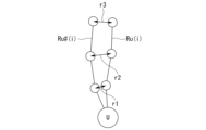
第4スコアSC4(i)は、予測経路Ru(i)と理想経路Ru#(i)との乖離度合いが大きい程、大きくなるように計算される。例えば、スコア計算部124は、ステップごとの予測経路Ru(i)と理想経路Ru#(i)のそれぞれの経路点の距離を二乗し、合計した値の平方を、第4スコアSC4(i)として算出する。図9は、第4スコアSC4(i)の計算過程について説明するための図である。図中、r1は予測経路Ru(i)と理想経路Ru#(i)のそれぞれの1ステップ目の経路点の間の距離、r2は予測経路Ru(i)と理想経路Ru#(i)のそれぞれの2ステップ目の経路点の間の距離、r3は予測経路Ru(i)と理想経路Ru#(i)のそれぞれの3ステップ目の経路点の間の距離である。第4スコアSC4(i)は、例えば√(r12+r22+r32)として求められる。
スコア計算部124は、経路候補Rmc(i)ごとの総合スコアSC(i)を計算した後、最も総合スコアSC(i)が小さかった経路候補Rmc(i)を選択し、移動体1の経路Rmとして駆動制御部140に出力する。駆動制御部140は、経路Rmに沿って移動体1が移動するように、移動体1に取り付けられた駆動装置30を制御する。
このように処理を行うことで、移動体1は、与えられた目的地点に向かうことでユーザUを目的地点まで先導(誘導)することと、自身の存在によって他の歩行者PがユーザUに接近し過ぎないようにすることとを並行して行うように制御される。例えば、歩行者PがユーザUに接近している場面においては、移動体1が歩行者PとユーザUの間に入って歩行者Pの接近を牽制するような経路候補Rmc(i)の総合スコアが比較的高くなる筈だからである。
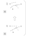
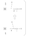
図10および図11は、移動体1がユーザUと歩行者Pの接近を抑制する場面を例示した図である。図10および図11において、左図は係数β=0として単に目的地点に向かうことのみを考慮した経路Rmが選択された場合の歩行者Pの移動経路を示し、右図は係数βを0よりも十分に大きくした場合の歩行者Pの移動経路を示している。図10の右図の例では、移動体1が右に膨らむ経路Rmをとることで、(影響力F1により)歩行者Pに左寄りの経路をとらせることで、歩行者PのユーザUへの接近を抑制している。図11の右図の例では、移動体1が敢えて低速で移動することで、(影響力F1により)歩行者Pに右寄りの経路をとらせることで、歩行者PのユーザUへの接近を抑制している。このように、制御装置100は、ユーザUに対して適切な挙動をするように移動体1の経路を生成することができる。
係数α、β、ζ、ηのそれぞれは、固定値であってもよいし任意に調整されるものであってもよい。
上記の説明において、制御装置100は、移動体1に搭載されるものとしたが、これに限らず、移動体1から離れた場所に設置され、通信によって物体検知デバイス20の出力データを取得すると共に、駆動指示信号を駆動装置30に送信するもの、つまり移動体1を遠隔制御するものであってもよい。
[フィルタ作成]
図12は、フィルタ作成装置200の構成図である。フィルタ作成装置200は、例えば、特徴量取得部210と、基準経路取得部220と、個別経路取得部230と、抽出部240と、学習部250と、シミュレータ270と、記憶部300とを備える。記憶部300以外の構成要素は、例えば、CPUなどのハードウェアプロセッサがプログラム(ソフトウェア)を実行することにより実現される。これらの構成要素のうち一部または全部は、LSIやASIC、FPGA、GPUなどのハードウェア(回路部;circuitryを含む)によって実現されてもよいし、ソフトウェアとハードウェアの協働によって実現されてもよい。プログラムは、予めHDDやフラッシュメモリなどの記憶装置(非一過性の記憶媒体を備える記憶装置)に格納されていてもよいし、DVDやCD-ROMなどの着脱可能な記憶媒体(非一過性の記憶媒体)に格納されており、記憶媒体がドライブ装置に装着されることで記憶装置にインストールされてもよい。
図12は、フィルタ作成装置200の構成図である。フィルタ作成装置200は、例えば、特徴量取得部210と、基準経路取得部220と、個別経路取得部230と、抽出部240と、学習部250と、シミュレータ270と、記憶部300とを備える。記憶部300以外の構成要素は、例えば、CPUなどのハードウェアプロセッサがプログラム(ソフトウェア)を実行することにより実現される。これらの構成要素のうち一部または全部は、LSIやASIC、FPGA、GPUなどのハードウェア(回路部;circuitryを含む)によって実現されてもよいし、ソフトウェアとハードウェアの協働によって実現されてもよい。プログラムは、予めHDDやフラッシュメモリなどの記憶装置(非一過性の記憶媒体を備える記憶装置)に格納されていてもよいし、DVDやCD-ROMなどの着脱可能な記憶媒体(非一過性の記憶媒体)に格納されており、記憶媒体がドライブ装置に装着されることで記憶装置にインストールされてもよい。
記憶部300は、RAM(Random Access Memory)、フラッシュメモリ、HDDなどである。記憶部300には、サンプルデータ310、モデル設定情報320などの情報が格納される。サンプルデータ310は、例えば、移動体1から見た歩行者の相対的な位置、速度、加速度、移動体1から見たユーザUの位置などの時系列データである。これに代えて、サンプルデータ310は、絶対座標系上の時系列データであってもよい。サンプルデータ310は、実環境で移動体1を移動させた際に取得されたデータであってもよいし、確率的計算に基づいて作成された仮想データであってもよい。以下の説明においても、フィルタ処理部115の説明と同様に、サンプルデータ310に含まれる歩行者Pのことを歩行者候補Pcと称する。モデル設定情報320は、フィルタプログラムとして機能する学習済モデルの元となる機械学習モデルの種類、層の数、ノードの接続情報などを規定した情報である。
特徴量取得部210は、サンプルデータから、複数の特徴量を導出する。複数の特徴量は、例えば以下のようなものである。特徴量の中には、シミュレータ270にシミュレーションを行わせることで導出されるものもあってよい。図13は、下記の特徴量のそれぞれを模式的に示した図である。紙面の都合上、適宜、特徴量ごとに歩行者候補Pcを分けている。
(1)歩行者候補Pcに位置が近い順にk人(図では2人)の他の歩行者候補Pcとの間の、所定の観測期間における最小距離Dminの平均値
(2)歩行者候補Pcの速度VPc
(3)ユーザUと移動体1を結ぶ直線から歩行者候補Pcまでの距離D1
(4)歩行者候補Pcが監視対象領域A1にいる時間の長さT1
(5)移動体1から見た歩行者候補Pcの向き(方位)θ
(6)移動体1の座標系(例えば基体5の中心軸を一つの座標軸とした座標系であり、図中、X、Y軸で表す)における歩行者候補Pcの向き(移動ベクトルまたは身体の向き)φ
(7)歩行者候補Pcの将来軌道を所定の基準で評価した振動量Viv
(1)歩行者候補Pcに位置が近い順にk人(図では2人)の他の歩行者候補Pcとの間の、所定の観測期間における最小距離Dminの平均値
(2)歩行者候補Pcの速度VPc
(3)ユーザUと移動体1を結ぶ直線から歩行者候補Pcまでの距離D1
(4)歩行者候補Pcが監視対象領域A1にいる時間の長さT1
(5)移動体1から見た歩行者候補Pcの向き(方位)θ
(6)移動体1の座標系(例えば基体5の中心軸を一つの座標軸とした座標系であり、図中、X、Y軸で表す)における歩行者候補Pcの向き(移動ベクトルまたは身体の向き)φ
(7)歩行者候補Pcの将来軌道を所定の基準で評価した振動量Viv
基準経路取得部220は、複数の歩行者候補Pcの存在に基づいて制御装置1の機能によって生成される移動体1の経路である基準経路を取得する。例えば、基準経路取得部220は、サンプルデータ310をシミュレータ270に与えることで、基準経路を取得する。シミュレータ270は、前述した制御装置100と同等の経路生成機能を有するもの(例えば仮想マシンまたは物理プロセッサ)である。
個別経路取得部230は、サンプルデータ310から歩行者候補Pcを1人ずつ順に選択し、選択した歩行者候補Pcを除いた残余の歩行者候補Pcの存在に基づいて、制御装置1の機能によって生成される移動体1の経路である個別経路を、歩行者候補Pcごとに取得する。例えば、基準経路取得部220は、サンプルデータ310から1人ずつ歩行者候補Pcを除いたデータをシミュレータ270に与えることで、個別経路を取得する。
抽出部240は、基準経路との差が他の個別経路に比して小さい個別経路を抽出する。例えば、抽出部240は、M人の歩行者候補Pcが残るように、歩行者候補Pcの数N人から、基準経路との差が他の個別経路に比して小さい順に(N-M)人の歩行者候補Pcを抽出する。「基準経路との差」とは、例えば、基準経路と個別経路を有限ステップ数に分割した場合に、各ステップにおける位置の差分についてRMSD(平均二乗偏差)を求めた値である。図14は、基準経路と個別経路との差について説明するための図である。図中、RPは基準経路であり、IPは個別経路であり、ΔYはいくつかのステップにおける位置の差分である。
図15は、上記説明したフィルタ作成装置200の処理の流れの一例を示すフローチャートである。まず、特徴量取得部210がサンプルデータ310から複数の歩行者候補Pcのそれぞれについて、複数の特徴量を導出する(S20)。次に、基準経路取得部220が、シミュレータ270を用いて基準経路を生成する(S21)。
次に、個別経路取得部230と抽出部240がサンプルデータ310に含まれる歩行者候補Pc(u)ごとにS22、S23の処理を実行する。パラメータuは歩行者候補Pcの識別子であり、u=1~Nである。まず、個別経路取得部230が、シミュレータ270を用いて、選択した歩行者候補Pc(u)を除いた残余の歩行者候補Pcの存在に基づいて、個別経路IP(u)を生成する(S22)。次に、抽出部240が、個別経路IP(u)と基準経路RPとの差ΔP(u)を計算する(S23)。
そして、抽出部240が、差ΔPが小さいものから順に、N-M人の歩行者候補Pcを抽出し、除外する歩行者候補とする(S24)。
学習部250は、機械学習によってフィルタとして機能する学習済モデルを生成する。学習部250は、抽出部240により抽出された歩行者候補Pc(以下、歩行者候補Pc(p)と表記する)の特徴量を正例の学習データ、抽出されなかった歩行者候補Pc(以下、歩行者候補Pc(n)と表記する)の特徴量を負例の学習データとする。そして、学習部250は、歩行者候補Pc(p)の特徴量が入力されると除外対象の歩行者であることを示す情報(例えば、除外対象とすべき確率、或いは除外対象であることを示すフラグ)が出力され、歩行者候補Pc(n)の特徴量が入力されると除外対象の歩行者でないことを示す情報が出力されるように、機械学習によって学習済モデルを生成する。
学習済モデルは、例えばランダムフォレストである。図16は、学習済モデルの内容の一例を模式的に示す図である。これに代えて、学習済モデルはDNN(Deep Neural Network)などの形態であってもよい。また、学習済モデルは、一人の歩行者候補Pcの特徴量が入力されると、当該歩行者候補が除外対象の歩行者であることを示す情報を出力するものに限らず、複数の歩行者候補Pcの特徴量が入力されると、どの歩行者候補Pcが除外対象の歩行者であるかを示す情報を出力するものであってもよい。後者の場合、特徴量が入力される歩行者候補Pcの数によって、それぞれの歩行者候補Pcを除外対象とするか否かを決定する基準(閾値等)が変動するように学習済モデルを作成してもよい。
[特徴量の絞り込み]
上記の説明において、特徴量は固定的に設定されるものとしたが、予め用意された、より多数の特徴量の中から絞り込まれたものであってもよい。例えば、上記説明した特徴量の他、(8)歩行者候補Pcと移動体1との距離、(9)歩行者候補PcとユーザUとの距離、(10)歩行者候補Pcと目的地との距離、(11)歩行者候補Pcの向きとユーザUと移動体1を結ぶ直線とのなす角度、(12)歩行者候補Pcの向きの振動量、(13)歩行者候補Pcの将来位置と移動体1との距離、などが予め用意されてもよい。この場合、フィルタ作成装置200は、歩行者候補Pcを絞り込むのと同様に、一つずつ特徴量を除外して学習済モデルを作成し、除外する歩行者候補Pcが他の学習済モデルと大きく変わらない学習済モデルに対応する特徴量を順に除外するようにしてもよい。
上記の説明において、特徴量は固定的に設定されるものとしたが、予め用意された、より多数の特徴量の中から絞り込まれたものであってもよい。例えば、上記説明した特徴量の他、(8)歩行者候補Pcと移動体1との距離、(9)歩行者候補PcとユーザUとの距離、(10)歩行者候補Pcと目的地との距離、(11)歩行者候補Pcの向きとユーザUと移動体1を結ぶ直線とのなす角度、(12)歩行者候補Pcの向きの振動量、(13)歩行者候補Pcの将来位置と移動体1との距離、などが予め用意されてもよい。この場合、フィルタ作成装置200は、歩行者候補Pcを絞り込むのと同様に、一つずつ特徴量を除外して学習済モデルを作成し、除外する歩行者候補Pcが他の学習済モデルと大きく変わらない学習済モデルに対応する特徴量を順に除外するようにしてもよい。
以上説明した実施形態によれば、監視対象の歩行者を適切に絞り込むように制御装置を支援することができる。
上記説明した実施形態は、以下のように表現することができる。
フィルタを作成するフィルタ作成装置であって、
前記フィルタは、歩行者が歩行する領域を自律的に移動する移動体を制御する制御装置であって、前記歩行者を含む物体を認識し、認識結果に基づいて前記移動体が将来進むべき経路を生成する制御装置が、監視対象の歩行者を絞り込むためのフィルタであり、
コンピュータによって読み込み可能な命令(computer-readable instructions)を格納する一以上の記憶媒体(storage medium)と、
前記一以上の記憶媒体に接続されたプロセッサと、を備え、
前記プロセッサは、前記コンピュータによって読み込み可能な命令を実行することにより(the processor executing the computer-readable instructions to:)、
サンプルとなる複数の歩行者の複数の特徴量を取得することと、
前記複数の歩行者の存在に基づいて前記制御装置の機能によって生成される前記移動体の経路である基準経路を取得することと、
前記複数の歩行者から一人ずつ除いた歩行者群の存在に基づいて前記制御装置の機能によって生成される前記移動体の経路である個別経路を取得することと、
前記基準経路との差が他の個別経路に比して小さい個別経路を抽出することと、
抽出した個別経路に対応する歩行者を抽出することと、
前記抽出した歩行者の特徴量が学習済モデルに入力されると除外対象の歩行者であることを示す情報が出力されるように、機械学習によって前記学習済モデルを生成することと、
を実行するフィルタ作成装置。
フィルタを作成するフィルタ作成装置であって、
前記フィルタは、歩行者が歩行する領域を自律的に移動する移動体を制御する制御装置であって、前記歩行者を含む物体を認識し、認識結果に基づいて前記移動体が将来進むべき経路を生成する制御装置が、監視対象の歩行者を絞り込むためのフィルタであり、
コンピュータによって読み込み可能な命令(computer-readable instructions)を格納する一以上の記憶媒体(storage medium)と、
前記一以上の記憶媒体に接続されたプロセッサと、を備え、
前記プロセッサは、前記コンピュータによって読み込み可能な命令を実行することにより(the processor executing the computer-readable instructions to:)、
サンプルとなる複数の歩行者の複数の特徴量を取得することと、
前記複数の歩行者の存在に基づいて前記制御装置の機能によって生成される前記移動体の経路である基準経路を取得することと、
前記複数の歩行者から一人ずつ除いた歩行者群の存在に基づいて前記制御装置の機能によって生成される前記移動体の経路である個別経路を取得することと、
前記基準経路との差が他の個別経路に比して小さい個別経路を抽出することと、
抽出した個別経路に対応する歩行者を抽出することと、
前記抽出した歩行者の特徴量が学習済モデルに入力されると除外対象の歩行者であることを示す情報が出力されるように、機械学習によって前記学習済モデルを生成することと、
を実行するフィルタ作成装置。
以上、本発明を実施するための形態について実施形態を用いて説明したが、本発明はこうした実施形態に何等限定されるものではなく、本発明の要旨を逸脱しない範囲内において種々の変形及び置換を加えることができる。
1 移動体
20 物体検知デバイス
30 駆動装置
100 制御装置
110 認識部
115 フィルタ処理部
120 経路生成部
122 経路候補設定部
124 スコア計算部
130 予測部
140 駆動制御部
200 フィルタ作成装置
210 特徴量取得部
220 基準経路取得部
230 個別経路取得部
240 抽出部
250 学習部
300 記憶部
310 サンプルデータ
320 モデル設定情報
20 物体検知デバイス
30 駆動装置
100 制御装置
110 認識部
115 フィルタ処理部
120 経路生成部
122 経路候補設定部
124 スコア計算部
130 予測部
140 駆動制御部
200 フィルタ作成装置
210 特徴量取得部
220 基準経路取得部
230 個別経路取得部
240 抽出部
250 学習部
300 記憶部
310 サンプルデータ
320 モデル設定情報
Claims (10)
- フィルタ作成装置がフィルタを作成するフィルタ作成方法であって、
前記フィルタは、歩行者が歩行する領域を自律的に移動する移動体を制御する制御装置であって、前記歩行者を含む物体を認識し、認識結果に基づいて前記移動体が将来進むべき経路を生成する制御装置が、監視対象の歩行者を絞り込むためのフィルタであり、
前記フィルタ作成方法は、
サンプルとなる複数の歩行者の複数の特徴量を取得することと、
前記複数の歩行者の存在に基づいて前記制御装置の機能によって生成される前記移動体の経路である基準経路を取得することと、
前記複数の歩行者から一人ずつ除いた歩行者群の存在に基づいて前記制御装置の機能によって生成される前記移動体の経路である個別経路を取得することと、
前記基準経路との差が他の個別経路に比して小さい個別経路を抽出することと、
抽出した個別経路に対応する歩行者を抽出することと、
前記抽出した歩行者の特徴量が学習済モデルに入力されると除外対象の歩行者であることを示す情報が出力されるように、機械学習によって前記学習済モデルを生成することと、
を備える、フィルタ作成方法。 - 前記複数の特徴量は、着目する歩行者に位置が近い順に所定人数の他の歩行者と、前記着目する歩行者との間の、所定の観測期間における最小距離の平均値を含む、
請求項1記載のフィルタ作成方法。 - 前記複数の特徴量は、前記歩行者の速度を含む、
請求項1記載のフィルタ作成方法。 - 前記制御装置は、前記移動体が先導対象者を先導しながら移動する経路を生成するものであり、
前記複数の特徴量は、前記移動体と前記先導対象者を結ぶ直線から前記歩行者までの距離を含む、
請求項1記載のフィルタ作成方法。 - 前記複数の特徴量は、前記歩行者が監視対象領域にいる時間の長さを含む、
請求項1記載のフィルタ作成方法。 - 前記複数の特徴量は、前記移動体から見た前記歩行者の方位を含む、
請求項1記載のフィルタ作成方法。 - 前記複数の特徴量は、前記移動体を基準とした座標系における前記歩行者の向きを含む、
請求項1記載のフィルタ作成方法。 - フィルタを作成するフィルタ作成装置であって、
前記フィルタは、歩行者が歩行する領域を自律的に移動する移動体を制御する制御装置であって、前記歩行者を含む物体を認識し、認識結果に基づいて前記移動体が将来進むべき経路を生成する制御装置が、監視対象の歩行者を絞り込むためのフィルタであり、
サンプルとなる複数の歩行者の複数の特徴量を取得する特徴量取得部と、
前記複数の歩行者の存在に基づいて前記制御装置の機能によって生成される前記移動体の経路である基準経路を取得する基準経路取得部と、
前記複数の歩行者から一人ずつ除いた歩行者群の存在に基づいて前記制御装置の機能によって生成される前記移動体の経路である個別経路を取得する個別経路取得部と、
前記基準経路との差が他の個別経路に比して小さい個別経路を抽出し、抽出した前記個別経路に対応する前記歩行者を抽出する抽出部と、
抽出された前記歩行者の特徴量が学習済モデルに入力されると除外対象の歩行者であることを示す情報が出力されるように、機械学習によって前記学習済モデルを生成する学習部と、
を備えるフィルタ作成装置。 - フィルタを作成するフィルタ作成装置に実行させるプログラムであって、
前記フィルタは、歩行者が歩行する領域を自律的に移動する移動体を制御する制御装置であって、前記歩行者を含む物体を認識し、認識結果に基づいて前記移動体が将来進むべき経路を生成する制御装置が、監視対象の歩行者を絞り込むためのフィルタであり、
前記フィルタ作成装置に、
サンプルとなる複数の歩行者の複数の特徴量を取得することと、
前記複数の歩行者の存在に基づいて前記制御装置の機能によって生成される前記移動体の経路である基準経路を取得することと、
前記複数の歩行者から一人ずつ除いた歩行者群の存在に基づいて前記制御装置の機能によって生成される前記移動体の経路である個別経路を取得することと、
前記基準経路との差が他の個別経路に比して小さい個別経路を抽出することと、
抽出した個別経路に対応する歩行者を抽出することと、
前記抽出した歩行者の特徴量が学習済モデルに入力されると除外対象の歩行者であることを示す情報が出力されるように、機械学習によって前記学習済モデルを生成することと、
を実行させるためのプログラム。 - 歩行者が歩行する領域を自律的に移動する移動体を制御する制御装置であって、前記歩行者を含む物体を認識し、認識結果に基づいて前記移動体が将来進むべき経路を生成する制御装置に適用されるフィルタ装置であって、
フィルタ作成装置が、
サンプルとなる複数の歩行者の複数の特徴量を取得することと、
前記複数の歩行者の存在に基づいて前記制御装置の機能によって生成される前記移動体の経路である基準経路を取得することと、
前記複数の歩行者から一人ずつ除いた歩行者群の存在に基づいて前記制御装置の機能によって生成される前記移動体の経路である個別経路を取得することと、
前記基準経路との差が他の個別経路に比して小さい個別経路を抽出することと、
抽出した個別経路に対応する歩行者を抽出することと、
前記抽出した歩行者の特徴量が学習済モデルに入力されると除外対象の歩行者であることを示す情報が出力されるように、機械学習によって前記学習済モデルを生成することと、
を実行することにより生成されたフィルタを用いて、前記制御装置が監視対象とする歩行者を絞り込む、
フィルタ装置。
Priority Applications (3)
| Application Number | Priority Date | Filing Date | Title |
|---|---|---|---|
| PCT/JP2023/035351 WO2025069293A1 (ja) | 2023-09-28 | 2023-09-28 | フィルタ作成方法、フィルタ作成装置、プログラム、およびフィルタ装置 |
| JP2025548155A JPWO2025069293A1 (ja) | 2023-09-28 | 2023-09-28 | |
| CN202380101669.7A CN121752969A (zh) | 2023-09-28 | 2023-09-28 | 过滤器制作方法、过滤器制作装置、程序及过滤器装置 |
Applications Claiming Priority (1)
| Application Number | Priority Date | Filing Date | Title |
|---|---|---|---|
| PCT/JP2023/035351 WO2025069293A1 (ja) | 2023-09-28 | 2023-09-28 | フィルタ作成方法、フィルタ作成装置、プログラム、およびフィルタ装置 |
Publications (1)
| Publication Number | Publication Date |
|---|---|
| WO2025069293A1 true WO2025069293A1 (ja) | 2025-04-03 |
Family
ID=95202663
Family Applications (1)
| Application Number | Title | Priority Date | Filing Date |
|---|---|---|---|
| PCT/JP2023/035351 Pending WO2025069293A1 (ja) | 2023-09-28 | 2023-09-28 | フィルタ作成方法、フィルタ作成装置、プログラム、およびフィルタ装置 |
Country Status (3)
| Country | Link |
|---|---|
| JP (1) | JPWO2025069293A1 (ja) |
| CN (1) | CN121752969A (ja) |
| WO (1) | WO2025069293A1 (ja) |
Citations (3)
| Publication number | Priority date | Publication date | Assignee | Title |
|---|---|---|---|---|
| JP2013064671A (ja) * | 2011-09-20 | 2013-04-11 | Advanced Telecommunication Research Institute International | 計測システムおよび計測方法 |
| JP2020055490A (ja) * | 2018-10-04 | 2020-04-09 | 関西電力株式会社 | 走行制御装置及び走行制御方法、並びに自動走行車 |
| JP2022100860A (ja) * | 2020-12-24 | 2022-07-06 | トヨタ自動車株式会社 | ロボット制御システム、ロボット制御方法、及びプログラム |
-
2023
- 2023-09-28 WO PCT/JP2023/035351 patent/WO2025069293A1/ja active Pending
- 2023-09-28 JP JP2025548155A patent/JPWO2025069293A1/ja active Pending
- 2023-09-28 CN CN202380101669.7A patent/CN121752969A/zh active Pending
Patent Citations (3)
| Publication number | Priority date | Publication date | Assignee | Title |
|---|---|---|---|---|
| JP2013064671A (ja) * | 2011-09-20 | 2013-04-11 | Advanced Telecommunication Research Institute International | 計測システムおよび計測方法 |
| JP2020055490A (ja) * | 2018-10-04 | 2020-04-09 | 関西電力株式会社 | 走行制御装置及び走行制御方法、並びに自動走行車 |
| JP2022100860A (ja) * | 2020-12-24 | 2022-07-06 | トヨタ自動車株式会社 | ロボット制御システム、ロボット制御方法、及びプログラム |
Also Published As
| Publication number | Publication date |
|---|---|
| CN121752969A (zh) | 2026-03-27 |
| JPWO2025069293A1 (ja) | 2025-04-03 |
Similar Documents
| Publication | Publication Date | Title |
|---|---|---|
| JP5746347B2 (ja) | 自律移動装置 | |
| WO2019124001A1 (ja) | 移動体挙動予測装置および移動体挙動予測方法 | |
| CN112180943B (zh) | 一种基于视觉图像和激光雷达的水下机器人导航避障方法 | |
| JP7625679B2 (ja) | 予測装置、予測方法、プログラムおよび車両制御システム | |
| JP7130062B2 (ja) | 経路決定方法 | |
| CN112686421B (zh) | 将来行动推定装置、将来行动推定方法及存储介质 | |
| JP7466407B2 (ja) | 将来行動推定装置、車両制御装置、将来行動推定方法、およびプログラム | |
| CN114667494A (zh) | 机器人控制模型学习方法、机器人控制模型学习装置、机器人控制模型学习程序、机器人控制方法、机器人控制装置、机器人控制程序以及机器人 | |
| CN113988196A (zh) | 一种机器人移动方法、装置、设备及存储介质 | |
| CN120368996A (zh) | 一种基于激光雷达和相机的导盲机器人的工作方法及系统 | |
| KR20230149709A (ko) | 그리드에서의 양방향 경로 최적화 | |
| CN121941626A (zh) | 基于树搜索扩展的轨迹规划 | |
| JP2021163215A (ja) | 移動体制御装置、移動体制御プログラム及び移動体 | |
| CN111673731B (zh) | 路径决定方法 | |
| WO2025069293A1 (ja) | フィルタ作成方法、フィルタ作成装置、プログラム、およびフィルタ装置 | |
| WO2025212139A2 (en) | Probabilistic collision detection system | |
| JP7584385B2 (ja) | 移動体制御装置、移動体、移動体制御方法、プログラム、および学習装置 | |
| JP7459238B2 (ja) | ユーザ選好による強化学習基盤の自律走行最適化方法およびシステム | |
| WO2024201818A1 (ja) | 制御装置、制御方法、およびプログラム | |
| WO2024195078A1 (ja) | 制御装置、制御方法、およびプログラム | |
| EP4617810A1 (en) | Control device, control method, and program | |
| WO2025069393A1 (ja) | 制御装置、制御方法、およびプログラム | |
| JP7720894B2 (ja) | 制御装置、制御方法、およびプログラム | |
| EP4718197A1 (en) | System and method for controlling mobile body, mobile body, and program | |
| CN121002460A (zh) | 控制装置、控制方法以及程序 |
Legal Events
| Date | Code | Title | Description |
|---|---|---|---|
| 121 | Ep: the epo has been informed by wipo that ep was designated in this application |
Ref document number: 23954269 Country of ref document: EP Kind code of ref document: A1 |
|
| ENP | Entry into the national phase |
Ref document number: 2025548155 Country of ref document: JP Kind code of ref document: A |