WO2025062835A1 - 給油ノズルのスイベルジョイント - Google Patents
給油ノズルのスイベルジョイント Download PDFInfo
- Publication number
- WO2025062835A1 WO2025062835A1 PCT/JP2024/027057 JP2024027057W WO2025062835A1 WO 2025062835 A1 WO2025062835 A1 WO 2025062835A1 JP 2024027057 W JP2024027057 W JP 2024027057W WO 2025062835 A1 WO2025062835 A1 WO 2025062835A1
- Authority
- WO
- WIPO (PCT)
- Prior art keywords
- main body
- fuel filler
- fuel
- bush
- nozzle
- Prior art date
- Legal status (The legal status is an assumption and is not a legal conclusion. Google has not performed a legal analysis and makes no representation as to the accuracy of the status listed.)
- Ceased
Links
Images



Classifications
-
- B—PERFORMING OPERATIONS; TRANSPORTING
- B67—OPENING, CLOSING OR CLEANING BOTTLES, JARS OR SIMILAR CONTAINERS; LIQUID HANDLING
- B67D—DISPENSING, DELIVERING OR TRANSFERRING LIQUIDS, NOT OTHERWISE PROVIDED FOR
- B67D7/00—Apparatus or devices for transferring liquids from bulk storage containers or reservoirs into vehicles or into portable containers, e.g. for retail sale purposes
- B67D7/06—Details or accessories
- B67D7/32—Arrangements of safety or warning devices; Means for preventing unauthorised delivery of liquid
-
- B—PERFORMING OPERATIONS; TRANSPORTING
- B67—OPENING, CLOSING OR CLEANING BOTTLES, JARS OR SIMILAR CONTAINERS; LIQUID HANDLING
- B67D—DISPENSING, DELIVERING OR TRANSFERRING LIQUIDS, NOT OTHERWISE PROVIDED FOR
- B67D7/00—Apparatus or devices for transferring liquids from bulk storage containers or reservoirs into vehicles or into portable containers, e.g. for retail sale purposes
- B67D7/06—Details or accessories
- B67D7/38—Arrangements of hoses, e.g. operative connection with pump motor
-
- B—PERFORMING OPERATIONS; TRANSPORTING
- B67—OPENING, CLOSING OR CLEANING BOTTLES, JARS OR SIMILAR CONTAINERS; LIQUID HANDLING
- B67D—DISPENSING, DELIVERING OR TRANSFERRING LIQUIDS, NOT OTHERWISE PROVIDED FOR
- B67D7/00—Apparatus or devices for transferring liquids from bulk storage containers or reservoirs into vehicles or into portable containers, e.g. for retail sale purposes
- B67D7/06—Details or accessories
- B67D7/42—Filling nozzles
-
- F—MECHANICAL ENGINEERING; LIGHTING; HEATING; WEAPONS; BLASTING
- F16—ENGINEERING ELEMENTS AND UNITS; GENERAL MEASURES FOR PRODUCING AND MAINTAINING EFFECTIVE FUNCTIONING OF MACHINES OR INSTALLATIONS; THERMAL INSULATION IN GENERAL
- F16J—PISTONS; CYLINDERS; SEALINGS
- F16J15/00—Sealings
- F16J15/16—Sealings between relatively-moving surfaces
- F16J15/32—Sealings between relatively-moving surfaces with elastic sealings, e.g. O-rings
- F16J15/3204—Sealings between relatively-moving surfaces with elastic sealings, e.g. O-rings with at least one lip
- F16J15/3232—Sealings between relatively-moving surfaces with elastic sealings, e.g. O-rings with at least one lip having two or more lips
- F16J15/3236—Sealings between relatively-moving surfaces with elastic sealings, e.g. O-rings with at least one lip having two or more lips with at least one lip for each surface, e.g. U-cup packings
-
- F—MECHANICAL ENGINEERING; LIGHTING; HEATING; WEAPONS; BLASTING
- F16—ENGINEERING ELEMENTS AND UNITS; GENERAL MEASURES FOR PRODUCING AND MAINTAINING EFFECTIVE FUNCTIONING OF MACHINES OR INSTALLATIONS; THERMAL INSULATION IN GENERAL
- F16N—LUBRICATING
- F16N5/00—Apparatus with hand-positioned nozzle supplied with lubricant under pressure
-
- F—MECHANICAL ENGINEERING; LIGHTING; HEATING; WEAPONS; BLASTING
- F16—ENGINEERING ELEMENTS AND UNITS; GENERAL MEASURES FOR PRODUCING AND MAINTAINING EFFECTIVE FUNCTIONING OF MACHINES OR INSTALLATIONS; THERMAL INSULATION IN GENERAL
- F16N—LUBRICATING
- F16N7/00—Arrangements for supplying oil or unspecified lubricant from a stationary reservoir or the equivalent in or on the machine or member to be lubricated
-
- B—PERFORMING OPERATIONS; TRANSPORTING
- B67—OPENING, CLOSING OR CLEANING BOTTLES, JARS OR SIMILAR CONTAINERS; LIQUID HANDLING
- B67D—DISPENSING, DELIVERING OR TRANSFERRING LIQUIDS, NOT OTHERWISE PROVIDED FOR
- B67D2210/00—Indexing scheme relating to aspects and details of apparatus or devices for dispensing beverages on draught or for controlling flow of liquids under gravity from storage containers for dispensing purposes
- B67D2210/00028—Constructional details
- B67D2210/00031—Housing
- B67D2210/00044—Insulation
-
- B—PERFORMING OPERATIONS; TRANSPORTING
- B67—OPENING, CLOSING OR CLEANING BOTTLES, JARS OR SIMILAR CONTAINERS; LIQUID HANDLING
- B67D—DISPENSING, DELIVERING OR TRANSFERRING LIQUIDS, NOT OTHERWISE PROVIDED FOR
- B67D2210/00—Indexing scheme relating to aspects and details of apparatus or devices for dispensing beverages on draught or for controlling flow of liquids under gravity from storage containers for dispensing purposes
- B67D2210/00028—Constructional details
- B67D2210/00047—Piping
- B67D2210/00062—Pipe joints
Definitions
- a fuel nozzle that is connected to the end of a fuel hose via a swivel joint is extremely useful because it improves the operability of the fuel nozzle and expands the fueling range (see, for example, Patent Document 1).
- a lubricant such as grease to ensure smooth rotation.
- lubricating oil may leak from the end of the swivel joint. Unlike fuel oil leakage, lubricating oil leakage does not cause serious problems and does not adversely affect the safety of refueling operations. However, users of the refueling device may mistake the leakage of lubricating oil for the leakage of fuel oil, become distrustful of the refueling device, and complain to the refueling facility.
- rainwater or water containing salt may seep into the inside of the swivel joint from the end of the swivel joint via a path in the opposite direction to the path from which the lubricating oil leaks, which may cause the iron ball of the swivel joint to rust. If the ball rusts, it will hinder the smooth rotation of the swivel joint and impair the operability of the fuel nozzle.
- the disinfectant sprayed on the fuel nozzle by staff at fueling facilities as a countermeasure against infectious diseases may contain components that break down grease. If such components seep into the inside of the swivel joint from the end, they will break down the lubricating oil and hinder the smooth rotation of the swivel joint.
- the fuel nozzle (Patent Document 1), which is connected to the end of the fuel hose via a swivel joint, is not intended to solve the problems of lubricating oil leaking out from the end of the swivel joint, or of rainwater, water containing salt, or disinfectants containing components that break down grease seeping into the swivel joint from the end of the swivel joint.
- the present invention has been proposed in consideration of the problems with the conventional technology described above, and aims to provide a swivel joint for a fuel nozzle that can prevent lubricating oil from leaking out from the end of the swivel joint and the infiltration of rainwater, salty water, or disinfectants containing components that break down grease from the end of the swivel joint.
- the swivel joint 10 of the fuel filler nozzle of the present invention comprises a cylindrical main body 2, a hollow fuel filler nozzle side bush 1 that fits into the fuel filler nozzle side end 2A of the main body 2, a hollow fuel filler hose side bush 3 that fits into the fuel filler hose side end 2B of the main body 2, a rotor 7 that is interposed between the fitting surfaces of the main body 2 and the fuel filler nozzle side bush 1 and between the main body 2 and the fuel filler hose side bush 3 and allows relative rotation between the main body 2 and the fuel filler nozzle side bush 1 and between the main body 2 and the fuel filler hose side bush 3, and rotor accommodating portions 4, 5 that accommodate the rotor and lubricating oil, and is characterized in that dust seals 9 are provided on the fitting surface of the main body 2 and the fuel filler nozzle side bush 1 in a region extending from the location of the rotor accommodating portion 4 toward the fuel filler nozzle side end 2A of the main body 2, and on the fitting surface
- the dust seal 9 arranged on the mating surface between the main body 2 and the fuel fill hose side bush 3 in the region extending from the location where the rotor accommodating portion 5 is located toward the fuel fill hose side end 2B of the main body 2 are preferably gaskets that are annular overall and have a U-shaped cross section.
- the dust seal 8 arranged on the mating surface between the main body 2 and the fuel filler nozzle side bush 1 in the region from where the rotor accommodating portion 4 is located toward the fuel filler nozzle side end 2A of the main body 2 is preferably arranged closer to the fuel filler nozzle side rotor accommodating portion 4 than the end face 2AA of the fuel filler nozzle side end 2A of the main body 2, and the dust seal 9 arranged on the mating surface between the main body 2 and the fuel filler hose side bush 3 in the region from where the rotor accommodating portion 5 is located toward the fuel filler hose side end 2B of the main body 2 is preferably arranged closer to the fuel filler hose side rotor accommodating portion 5 than the end face of the fuel filler hose side end 2B of the main body 2.
- dust seals 8 and 9 are arranged on the mating surface between the main body 2 and the fuel filler nozzle side bush 1 in the area extending from the location where the rotor accommodating portion 4 is located toward the fuel filler nozzle side end 2A of the main body 2, and on the mating surface between the main body 2 and the fuel filler hose side bush 3 in the area extending from the location where the rotor accommodating portion 5 is located toward the fuel filler hose side end 2B of the main body 2. Therefore, the lubricating oil accommodated in the nozzle side rotor accommodating portion 4 and the fuel filler hose side rotor accommodating portion 5 is sealed in each of the above areas, and is prevented from leaking outside the swivel joint 10.
- the dust seal 8 on the fuel nozzle side and the dust seal 9 on the fuel hose side prevent rainwater, salty water, disinfectant, etc. from entering the inside of the seals 8, 9 (the rotor housing parts 4, 5 side) from the outside. This prevents the boundary inside the seals 8, 9 (the rotor housing parts 4, 5 side) from rusting and prevents the lubricating oil contained in the rotor housing parts 4, 5 from being decomposed by the components of the disinfectant.
- the dust seal 8 on the fuel filler nozzle side is not provided at a position corresponding to the end face 2AA of the main body 2, and the dust seal 9 on the fuel filler hose side is not provided at a position corresponding to the end face of the fuel filler hose side end 2B of the main body 2. Therefore, particularly when the dust seals 8, 9 are U-packings, the lip of the U-packing is prevented from penetrating into the gap that occurs between the bushes 1, 3 and the end face 2AA of the main body 2, and there is no risk of the sealing performance of the U-packing being lost.
- FIG. 1 is a cross-sectional view showing an example of a swivel joint of a conventional fuel filling nozzle.
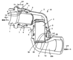
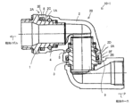
- 1 is a cross-sectional view showing an embodiment of a swivel joint of a fuel filling nozzle according to the present invention.
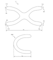
- FIG. 13 is a diagram showing the disadvantages of X-packing in comparison with U-packing.
- FIG. 4 is a diagram of a different type of U-packing than that shown in FIG. 3 .
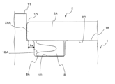
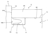
- 13 is a partial cross-sectional view showing a state in which a U-packing is provided near the end of the main body.
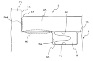
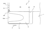
- FIG. 13 is a partial cross-sectional view showing a problem that occurs when a U-packing is provided at a position separated from the end of the main body.
- FIG. 13 is a partial cross-sectional view showing a problem that occurs when a U-packing is provided at a position corresponding to an end face of a main body.
- 8 is an enlarged partial cross-sectional view showing a gap that occurs between an end face of a main body and an end face of a bushing protruding portion due to tolerance in the state shown in FIG. 7 .
- 9 is an enlarged partial cross-sectional view showing a state in which a lip of a U-packing has entered a gap between an end face of a main body and an end face of a bushing protruding portion in the state shown in FIG. 8 .
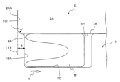
- FIG. 1 is an enlarged partial cross-sectional view showing the distance between the end face of a groove that accommodates a U-packing and an extension line of the end face of the main body.
- FIG. 11 is a cross-sectional view showing a modified example in which a dust seal is provided on the main body side.
- this swivel joint 20 comprises a fuel fill nozzle side bush (hereafter referred to as "bush") 1, a main body 2, and a fuel fill hose side bush (hereafter referred to as "bush") 3.
- the main body 2 and bushes 1 and 3 are configured to be hollow, with bush 1 fitting into the inner circumferential surface 2C of the nozzle side end 2A of the main body 2, and bush 3 fitting into the inner circumferential surface 2D of the hose side end 2B of the main body 2.
- Bush 1 is connected to a fuel fill nozzle (not shown in FIG. 1), and bush 3 is connected to a fuel fill hose (not shown) via a swivel elbow 20A.
- the swivel joint 20 has a portion on the bush 1 side (nozzle-side rotating body housing 4) in which a rotating body 7 such as a ball is housed, and a portion on the bush 3 side (hose-side rotating body housing 5) in which the rotating body 7 is housed.
- the main body 2 is provided with grease injection nipples for injecting grease (lubricating oil) into the rotating body housing portions 4 and 5.
- the rotating body 7 is inserted into the rotating body housing portions 4 and 5 through holes that fasten the grease injection nipples.
- the bushes 1 and 3 have bush protrusions T1 and T2 that protrude radially outward, and the ends 2A and 2B of the main body 2 face the bush protrusions T1 and T2, respectively.
- a fuel oil seal member 6 e.g., a U-packing
- the fuel oil seal member 6 is provided to prevent the fuel oil flowing inside the swivel joint 20 from leaking to the outside.
- this swivel joint 10 has components equivalent to the bushes 1 and 3, main body 2, fuel filler nozzle side rotor housing 4, fuel filler hose side rotor housing 5, fuel oil seal member 6, etc. Duplicate explanation of the same configuration as in Fig. 1 will be avoided.
- dust seals 8 and 9 that seal the boundaries between the inner circumferential surfaces 2C and 2D of the main body 2 at the ends 2A and 2B (the ends of the main body refer to the areas outside the rotor housing) and the bush outer circumferential surfaces 1A and 3A are provided on the outer circumferential surfaces 1A and 3A of the bushes 1 and 3.
- the dust seals 8 and 9 are positioned so that their lips face the bush protrusions T1 and T2.
- the dust seals 8, 9 are positioned closer to the bushing protrusions T1, T2 than the rotor housings 4, 5, so that the grease contained in the rotor housings 4, 5 is prevented from leaking out of the swivel joint 10 from the boundaries between the inner circumferential surfaces 2C, 2D at the ends 2A, 2B of the main body 2 and the outer circumferential surfaces 1A, 3A of the bushing. Furthermore, rainwater, salty water, disinfectant, etc.
- the dust seals 8 and 9 are preferably U-shaped packings, which are generally annular and have a U-shaped cross section. As described above, the open U-shaped sides of the dust seals 8 and 9 face the ends 2A and 2B of the main body 2. Therefore, the open U-shaped sides prevent disinfectants, rust inhibitors, rainwater, salty water, and other foreign matter from outside the swivel joint 10 from entering through the boundary between the main body 2 and the bushes 1 and 3. If the grease contained in the rotating body accommodating parts 4 and 5 attempts to leak out of the swivel joint 10 through the boundary between the main body 2 and the bushes 1 and 3, it is sealed by the closed U-shaped sides of the dust seals 8 and 9. Since there is no pressure difference between the rotating body accommodating parts 4 and 5 and the outside of the swivel joint 10, the closed U-shaped side of the U-packing can be sufficiently sealed to prevent the grease from leaking out.
- the U-packing that can be used is one that has a lip not only on the open side (the right side in Figure 4) but also on the opposite side (the so-called "closed side of the U”).
- the open U-shaped side of the modified U-packing 12 (the lip 12A side) is positioned so that it faces the fuel filler nozzle side end 2A of the main body 2 or the bush protrusion T1 of the bush 1, i.e., facing outward.
- an O-ring or X-ring can also be used as a dust seal.
- the fuel nozzle side end face 1BA of the recess 1C is located on the opposite side (right side in FIG. 5) from the fuel nozzle side with respect to the body side end face 1D of the protrusion T1 located radially outward (upward in FIG. 5).
- the fuel nozzle side end face 1BA of the recess 1C into which the dust seal 8 is inserted is located very close to the fuel nozzle side end face 2AA of the body 2, but is not provided at a position corresponding to the end face 2AA of the body 2 (a position flush with the end face 2AA).
- the fuel nozzle side end face 1BA of the recess 1C is located on the fuel nozzle side rotating body accommodating portion 4 side (right side in FIG.
- a dust seal 8 is placed in a position close to the fuel nozzle side end face 2AA of the main body 2, so as to prevent foreign matter from entering the area on the fuel nozzle side rotating body housing part 4 side (right side in FIG. 6) of the boundary between the main body 2 and the bush 1 as much as possible.
- the length dimensions LN and LH in FIG. 2 become longer.
- the dimensions LN and LH become shorter as the dust seals 8 and 9 are closer to the body ends 2A and 2B, and longer as they are farther away. If the dimensions LN and LH are long, the weight of the body 2, which is a casting, increases accordingly, and the operability of the fuel nozzle deteriorates. Furthermore, if the dimensions LN and LH are long, the body 2 and the bushes 1 and 3 tend to interfere with each other during relative rotation (so-called "easiness to gall"), and the sliding resistance increases. For the above reasons, in the illustrated embodiment, the dust seals 8 and 9 are arranged close to the body ends 2A and 2B (see FIG.
- the dust seals 8 and 9 are arranged on the fuel nozzle side, they are located very close to the end face 2AA of the body on the fuel nozzle side, and if they are arranged on the side of the rotating body accommodating portion 4 on the fuel nozzle side of the end face 2AA of the body 2, the dimension LN becomes longer by the minimum necessary length even if the dust seal 8 is arranged. Therefore, the weight of the bush 1 and the main body 2 does not increase significantly, and the operability of the swivel joint 10 of the fuel nozzle is not reduced. In addition, interference between the rotating parts (so-called "galling") during relative rotation between the bush 1 and the main body 2 is less likely to occur. Also, the area through which rainwater, salty water, or disinfectant solution can penetrate into the fuel nozzle side rotor housing 4 is reduced.
- Figs. 7 to 10 explain the dust seal 8 that is placed near the end 2A of the main body 2 on the fuel filler nozzle side, but the same is true for the dust seal 9 that is placed near the end 2B of the main body 2 on the fuel filler hose side.
- the end face 1BA (the left end face in Fig. 7) of the recess 1C that houses the dust seal 8 and the end face 1D of the bushing protrusion T1 are flush with each other.
- the end face 1D of the bushing protrusion T1 and the end face 2AA of the main body 2 on the fuel filler nozzle side are in contact with each other.
- the sealing performance of the dust seal 8 does not deteriorate.
- the lip 8A that has entered may be damaged by the relative rotation of the main body 2 and the bushing 1, and the sealing performance of the dust seal 8 may be lost.
- the grease in the fuel nozzle side rotating body housing 4 may leak, or rainwater, water containing salt, or disinfectant containing a component that breaks down grease may penetrate into the boundary between the bushing 1 and the main body 2.
- the tip of the lip 8A of the dust seal 8 gets into the gap, the dust seal 8 cannot move in the direction of the arrow ⁇ in FIG. 9 (towards the nozzle-side rotor housing 4, not shown).
- the end face 1BA of the recess 1C that houses the dust seal 8 is not disposed in a position corresponding to the body end face 2AA, and is not flush with the end face 1D of the bushing protrusion T1.
- the end face 1BA (left end face in FIG. 10) of the recess 1C that houses the dust seal 8 is disposed so as to be at least the radius of curvature r of the corner radius at the body end face 2AA (right side in FIG. 10) inward from the imaginary extension line L11 of the end face 1D of the bushing protrusion T1.
- At least the radius of curvature r of the corner radius at the body end face 2AA is an example of the "dimension ⁇ " described above with reference to FIG. 10. This eliminates the need for strict tolerances to prevent the formation of a gap between the end face 1D of the bushing protrusion T1 and the end face 2AA of the body as in FIG. 9, and allows the cost of member production to be maintained.
- the dust seals 8, 9 are provided on the outer circumferential surfaces 1A, 3A of the bush.
- the dust seals 8, 9 can be provided on the inner circumferential surface 2C of the main body 2 on the fuel nozzle side and the inner circumferential surface 2D of the main body 2 on the fuel hose side.
- the dust seals 8, 9 that seal the boundaries between the inner circumferential surfaces 2C, 2D at the ends 2A, 2B of the main body 2 and the outer circumferential surfaces 1A, 3A of the bush are provided on the inner circumferential surfaces 2C, 2D of the main body 2.
- the areas radially outward of the dust seals 8, 9 are provided with built-up portions 2E, 2F, and the thickness dimensions of the locations where the dust seals 8, 9 are arranged are set large.
- the other configurations and effects of the modified example in Fig. 11 are the same as those of the embodiment in Figs. 2 to 10.
- REFueling nozzle side bushing 1A Fueling nozzle side bushing outer surface 1B: End 1BA: Fueling nozzle side end surface 1C: Recess 2: Main body 2A: Fueling nozzle side end 2AA: Fueling nozzle side end surface 2B: Fueling hose side end 2C: Inner circumferential surface at the fueling nozzle side end of the main body 2D: Inner circumferential surface at the fueling hose side end of the main body 3: Fueling hose side bushing 3A: Fueling hose side bushing outer surface 3B: End 4: Fueling nozzle side rotating body accommodating portion 5: Fueling hose side rotating body accommodating portion 6: Fuel oil seal member 7: Rotating body 8: Nozzle side dust seal 8A: Lip 9: Hose side dust seal 10: Fueling nozzle swivel joint 11: X packing 11A: Lip 12: Deformed U packing 12A: Lip
Landscapes
- Engineering & Computer Science (AREA)
- Mechanical Engineering (AREA)
- General Engineering & Computer Science (AREA)
- Joints Allowing Movement (AREA)
Priority Applications (3)
| Application Number | Priority Date | Filing Date | Title |
|---|---|---|---|
| KR1020267007338A KR20260069566A (ko) | 2023-09-20 | 2024-07-30 | 급유노즐의 스위블 조인트 |
| JP2025547212A JPWO2025062835A1 (cg-RX-API-DMAC7.html) | 2023-09-20 | 2024-07-30 | |
| CN202480060095.8A CN121889332A (zh) | 2023-09-20 | 2024-07-30 | 供油喷嘴的旋转接头 |
Applications Claiming Priority (2)
| Application Number | Priority Date | Filing Date | Title |
|---|---|---|---|
| JP2023-151899 | 2023-09-20 | ||
| JP2023151899 | 2023-09-20 |
Publications (1)
| Publication Number | Publication Date |
|---|---|
| WO2025062835A1 true WO2025062835A1 (ja) | 2025-03-27 |
Family
ID=95072765
Family Applications (1)
| Application Number | Title | Priority Date | Filing Date |
|---|---|---|---|
| PCT/JP2024/027057 Ceased WO2025062835A1 (ja) | 2023-09-20 | 2024-07-30 | 給油ノズルのスイベルジョイント |
Country Status (4)
| Country | Link |
|---|---|
| JP (1) | JPWO2025062835A1 (cg-RX-API-DMAC7.html) |
| KR (1) | KR20260069566A (cg-RX-API-DMAC7.html) |
| CN (1) | CN121889332A (cg-RX-API-DMAC7.html) |
| WO (1) | WO2025062835A1 (cg-RX-API-DMAC7.html) |
Citations (2)
| Publication number | Priority date | Publication date | Assignee | Title |
|---|---|---|---|---|
| US5209262A (en) * | 1991-01-15 | 1993-05-11 | Carow Walter M | Breakaway hose coupling with integrated swivel mechanism |
| JP2013160343A (ja) * | 2012-02-07 | 2013-08-19 | Ntn Corp | 車輪用軸受装置 |
-
2024
- 2024-07-30 JP JP2025547212A patent/JPWO2025062835A1/ja active Pending
- 2024-07-30 KR KR1020267007338A patent/KR20260069566A/ko active Pending
- 2024-07-30 WO PCT/JP2024/027057 patent/WO2025062835A1/ja not_active Ceased
- 2024-07-30 CN CN202480060095.8A patent/CN121889332A/zh active Pending
Patent Citations (2)
| Publication number | Priority date | Publication date | Assignee | Title |
|---|---|---|---|---|
| US5209262A (en) * | 1991-01-15 | 1993-05-11 | Carow Walter M | Breakaway hose coupling with integrated swivel mechanism |
| JP2013160343A (ja) * | 2012-02-07 | 2013-08-19 | Ntn Corp | 車輪用軸受装置 |
Also Published As
| Publication number | Publication date |
|---|---|
| CN121889332A (zh) | 2026-04-17 |
| JPWO2025062835A1 (cg-RX-API-DMAC7.html) | 2025-03-27 |
| KR20260069566A (ko) | 2026-05-15 |
Similar Documents
| Publication | Publication Date | Title |
|---|---|---|
| US6315296B1 (en) | Flangeless retrofittable severe duty seal for a shaft | |
| US6991234B2 (en) | Retrofittable severe duty seal for a shaft | |
| US20100148572A1 (en) | Sealing assembly and hinge of track having the sealing assembly | |
| US5597168A (en) | Single split oil seal | |
| US20080131044A1 (en) | Antifriction Bearing for Supporting an Axle or Journal | |
| GB2517573A (en) | Dynamically non contacting seal | |
| JP2011174570A (ja) | 密封装置 | |
| CN111396658A (zh) | 改进型防漏通用哈夫节组件 | |
| GB2321508A (en) | Sealing arrangement in a swivel joint | |
| KR20260069566A (ko) | 급유노즐의 스위블 조인트 | |
| JP3407436B2 (ja) | 密封装置 | |
| KR20230063366A (ko) | 밸브 코어 어셈블리 및 전자 팽창 밸브 | |
| WO2024262211A1 (ja) | 給油ノズルのスイベルジョイント | |
| JP3427992B2 (ja) | コネクターとパイプの接続構造体 | |
| CN212838925U (zh) | 一种转动轴的安装结构 | |
| JP2010060120A (ja) | 密封装置 | |
| JPH10159983A (ja) | 密封装置 | |
| CN112081813A (zh) | 一种转动轴的安装结构 | |
| US12006979B2 (en) | Bearing seat assembly | |
| WO2000029768A1 (en) | Seal assembly with an interlocking load ring | |
| KR102581288B1 (ko) | 자동변속기의 오일 씰 | |
| RU2235034C1 (ru) | Каток гусеничного транспортного средства | |
| US20100183255A1 (en) | Seal Guard | |
| KR100534992B1 (ko) | 실린더헤드 패킹구조 | |
| JP7353947B2 (ja) | 密封装置 |
Legal Events
| Date | Code | Title | Description |
|---|---|---|---|
| 121 | Ep: the epo has been informed by wipo that ep was designated in this application |
Ref document number: 24867916 Country of ref document: EP Kind code of ref document: A1 |
|
| ENP | Entry into the national phase |
Ref document number: 2025547212 Country of ref document: JP Kind code of ref document: A |
|
| WWE | Wipo information: entry into national phase |
Ref document number: 2025547212 Country of ref document: JP |
|
| WWE | Wipo information: entry into national phase |
Ref document number: 202617021908 Country of ref document: IN |
|
| WWP | Wipo information: published in national office |
Ref document number: 202617021908 Country of ref document: IN |
|
| NENP | Non-entry into the national phase |
Ref country code: DE |