WO2025062534A1 - ウエハ載置台 - Google Patents
ウエハ載置台 Download PDFInfo
- Publication number
- WO2025062534A1 WO2025062534A1 PCT/JP2023/034118 JP2023034118W WO2025062534A1 WO 2025062534 A1 WO2025062534 A1 WO 2025062534A1 JP 2023034118 W JP2023034118 W JP 2023034118W WO 2025062534 A1 WO2025062534 A1 WO 2025062534A1
- Authority
- WO
- WIPO (PCT)
- Prior art keywords
- heat transfer
- transfer liquid
- recess
- wafer
- flow path
- Prior art date
- Legal status (The legal status is an assumption and is not a legal conclusion. Google has not performed a legal analysis and makes no representation as to the accuracy of the status listed.)
- Pending
Links
Images




Classifications
-
- H—ELECTRICITY
- H10—SEMICONDUCTOR DEVICES; ELECTRIC SOLID-STATE DEVICES NOT OTHERWISE PROVIDED FOR
- H10P—GENERIC PROCESSES OR APPARATUS FOR THE MANUFACTURE OR TREATMENT OF DEVICES COVERED BY CLASS H10
- H10P72/00—Handling or holding of wafers, substrates or devices during manufacture or treatment thereof
- H10P72/70—Handling or holding of wafers, substrates or devices during manufacture or treatment thereof for supporting or gripping
Definitions
- the present invention relates to a wafer mounting table.
- the mounting table described in Patent Document 1 is provided with a backside gas supply pipe for supplying a heat transfer gas (backside gas) between the back surface of the mounted wafer and the mounting surface of the mounting table.
- the heat transfer gas promotes heat exchange between the mounting table and the wafer. It is described that helium gas or the like is used as the heat transfer gas.
- the present invention was made to solve these problems, and its main objective is to provide a wafer support that can increase the thermal conductivity between the wafer and the support.
- the present invention takes the following measures to achieve the above-mentioned main objective.
- the wafer mounting table of the present invention comprises: a ceramic base having, on its upper surface, a support surface for supporting a wafer and a recess recessed from the support surface; a heat transfer liquid flow path provided at least inside the ceramic base and serving as a flow path for a heat transfer liquid between the outside and an inside of the recess; It is equipped with the following:
- heat transfer liquid can be supplied to the inside of the recess in the upper surface of the ceramic base through the heat transfer liquid flow path.
- heat transfer liquid rather than heat transfer gas, can be supplied to the space between the wafer placed on the support surface and the inner peripheral surface of the recess. Since liquids generally have a higher thermal conductivity than gases, by having such a recess and heat transfer liquid flow path in the wafer mounting table, the thermal conductivity between the wafer and the wafer mounting table can be increased.
- the recess may have a reference surface that is lower than the support surface and a groove portion formed in the reference surface, and the groove portion may be arranged from the opening of the heat transfer liquid flow path to the recess toward the periphery of the opening.
- the groove portion may be provided in multiple portions.
- a plurality of the heat transfer liquid flow paths may be provided, each having an opening to the recess.
- one or more of the plurality of heat transfer liquid flow paths can be used as an inlet of the heat transfer liquid flow path, and the remaining can be used as an outlet. This allows the heat transfer liquid to be efficiently supplied to and discharged from the recess.
- the recess may have a reference surface that is lower than the support surface and a groove portion formed in the reference surface, and the groove portion may be provided to connect two or more of the plurality of openings.
- the groove portion may be provided to connect, among the plurality of openings, an opening that serves as an inlet and an opening that serves as an outlet for the heat transfer liquid into the recess.
- the wafer stage described above (the stage described in any one of [1] to [4] above) may have the heat transfer liquid placed in the recess.
- the ceramic base may have an electrostatic electrode built in, and the heat transfer liquid may be insulating.
- the wafer can be attracted and fixed to the support surface of the ceramic base by electrostatic attraction force by applying a voltage to the electrostatic electrode.
- the heat transfer liquid is insulating, it is less likely to interfere with the attraction and fixation of the wafer by electrostatic attraction force.
- the heat transfer liquid may be synthetic oil.
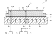
- FIG. 2 is a cross-sectional view taken along line AA in FIG. 1 .
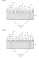
- FIG. 4 is a partially enlarged cross-sectional view showing details of the recess 25 and the heat transfer liquid flow path 50.
- FIG. 4 is a partially enlarged cross-sectional view showing a state of a recess 25 of the wafer mounting table 10 when in use.
- FIG. 4 is a plan view showing the groove 127 and the heat transfer liquid flow path 150.
- FIG. 4 is a plan view showing the groove portion 227 and the heat transfer liquid flow path 250.
- FIG. 4 is a plan view showing the groove 327 and the heat transfer liquid flow path 350.
- FIG. 1 is a plan view of the wafer mounting table 10
- FIG. 2 is a cross-sectional view taken along line A-A in FIG. 1
- FIG. 3 is a partially enlarged cross-sectional view showing details of the recess 25 and the heat transfer liquid flow path 50.
- FIG. 3 corresponds to an enlarged view of a portion of the cross-section shown in FIG. 2.
- the wafer mounting table 10 includes a ceramic base 20, a conductive plate 30, a conductive bonding layer 40, and a heat transfer liquid flow path 50.
- the wafer mounting table 10 is also connected to a switching valve 70, a heat transfer liquid supply source 71, a positive pressure supply source 72, and a negative pressure supply source 73.
- the ceramic base 20 is a ceramic disk (e.g., 300 mm in diameter and 5 mm in thickness) made of sintered alumina or sintered aluminum nitride.
- the upper surface of the ceramic base 20 serves as a wafer mounting surface 21 on which a wafer W is placed.
- the ceramic base 20 has an electrode 29 built in.
- the wafer mounting surface 21 of the ceramic base 20 has a support surface 22 that supports the wafer W, and a recess 25 recessed from the support surface 22.
- a ring-shaped seal band 23 is formed along the outer edge of the wafer mounting surface 21, and a plurality of circular small protrusions 24 are formed on the entire inner surface of the seal band 23.
- the upper surface of the seal band 23 and the upper surface of the circular small protrusions 24 are at the same height, and the upper surfaces of the seal band 23 and the circular small protrusions 24 form the support surface 22.
- a recess 25 is provided on the inner side of the seal band 23. As shown in FIG.
- the recess 25 is formed as a circular area (excluding the part where the support surface 22 is present, i.e., the part where the circular small protrusions 24 are present) on the inner side of the seal band 23 when viewed from above.
- the recess 25 has a reference surface 26 that is located lower than the support surface 22, and a groove portion 27 formed in the reference surface 26. Therefore, the bottom surface of the groove portion 27 is located lower than the reference surface 26.
- the recess 25 has an opening 51 of the heat transfer liquid flow path 50.
- multiple (here, two) heat transfer liquid flow paths 50a, 50b are formed as the heat transfer liquid flow path 50, and each opening 51a, 51b opens into the recess 25.
- the groove 27 is formed in a single stroke from one end (the end located near the center of the recess 25) to the other end (the end located near the outer periphery of the recess 25) in a top view. More specifically, the groove 27 is formed by being drawn in a spiral from one end to the other end. As a result, the groove 27 is drawn over almost the entire recess 25. The groove 27 is arranged so as to avoid the small circular protrusion 24 in a top view.
- the opening 51a of the heat transfer liquid flow path 50a is open at one end of the groove 27, and the opening 51b of the heat transfer liquid flow path 50b is open at the other end.
- the groove 27 is formed so as to move from one end toward the periphery of the opening 51a (moving away from the opening 51a). Similarly, the groove 27 is formed so as to move from the other end toward the periphery of the opening 51b (moving away from the opening 51b). The groove 27 is also provided to connect the opening 51a and the opening 51b.
- the seal band 23 and the small circular protrusions 24 have the same height from the reference surface 26, which is, for example, 5 ⁇ m to 50 ⁇ m.
- the depth of the groove 27 (the height from the reference surface 26 to the bottom surface of the groove 27) is, for example, 30 ⁇ m to 100 ⁇ m. In this embodiment, the depth of the groove 27 is greater than the height of the seal band 23 and the small circular protrusions 24 from the reference surface 26.
- the electrode 29 is a planar mesh electrode used as an electrostatic electrode, and is connected to an external DC power source via a power supply member (not shown).
- the layer of the ceramic base 20 above the electrode 29 functions as a dielectric layer.
- a low-pass filter may be disposed midway along the power supply member.
- the power supply member is electrically insulated from the conductive bonding layer 40 and the conductive plate 30.
- the conductive plate 30 is a disk with good thermal conductivity (a disk with the same diameter as or larger than the ceramic base 20). Inside the conductive plate 30, a refrigerant flow path 32 is formed through which the refrigerant circulates.
- the refrigerant flowing through the refrigerant flow path 32 is preferably liquid and preferably electrically insulating.
- An example of an electrically insulating liquid is a fluorine-based inert liquid.
- the refrigerant flow path 32 is formed in a single stroke from one end (inlet) to the other end (outlet) over the entire conductive plate 30 in a plan view.
- a supply port and a recovery port of an external refrigerant device (not shown) are connected to one end and the other end of the refrigerant flow path 32, respectively.
- the refrigerant supplied to one end of the refrigerant flow path 32 from the supply port of the external refrigerant device passes through the refrigerant flow path 32, returns from the other end of the refrigerant flow path 32 to the recovery port of the external refrigerant device, and is supplied again from the supply port to one end of the refrigerant flow path 32 after being temperature-adjusted.
- the conductive plate 30 is connected to a radio frequency (RF) power source and is also used as an RF electrode.
- the material of the conductive plate 30 may be, for example, a metal material or a composite material of metal and ceramic.
- the metal material may be Al, Ti, Mo, or an alloy thereof.
- the composite material of metal and ceramic may be a metal matrix composite material (MMC) or a ceramic matrix composite material (CMC ) .
- MMC metal matrix composite material
- CMC ceramic matrix composite material
- Specific examples of such composite materials include a material containing Si, SiC, and Ti (also called SiSiCTi), a material in which a SiC porous body is impregnated with Al and/or Si, and a composite material of Al2O3 and TiC. It is preferable to select a material of the conductive plate 30 having a thermal expansion coefficient close to that of the material of the ceramic base 20.
- the conductive bonding layer 40 is, for example, a metal bonding layer, and bonds the lower surface of the ceramic base 20 and the upper surface of the conductive plate 30.
- the conductive bonding layer 40 is formed, for example, by TCB (thermal compression bonding).
- TCB is a known method in which a metal bonding material is sandwiched between two members to be joined, and the two members are pressure-bonded while being heated to a temperature below the solidus temperature of the metal bonding material.
- the heat transfer liquid flow path 50 is provided at least inside the ceramic base 20 and functions as a flow path for the heat transfer liquid 75 (see FIG. 4B described later) between the outside of the wafer mounting table 10 and the inside of the recess 25.
- the heat transfer liquid flow path 50 is formed as a heat transfer liquid flow path 50 by a heat transfer liquid flow path 50a and a heat transfer liquid flow path 50b.
- the heat transfer liquid flow path 50a has a ceramic base penetration portion 52, a bonding layer penetration portion 54, and a conductive plate penetration portion 56.
- the ceramic base penetration portion 52 is provided inside the ceramic base 20 and is a hole that penetrates the ceramic base 20 from top to bottom.
- the bonding layer penetration portion 54 is a hole that penetrates the conductive bonding layer 40 from top to bottom.
- the conductive plate penetration portion 56 is a hole that penetrates the conductive plate 30 from top to bottom.
- the opening 51a at the upper end of the ceramic base penetration portion 52 of the heat transfer liquid flow path 50a opens to the bottom surface of one end of the groove portion 27 as described above.
- the ceramic base through-hole 52, the bonding layer through-hole 54, and the conductive plate through-hole 56 of the heat transfer liquid flow path 50a are connected in this order, and the heat transfer liquid flow path 50a is configured as a through-hole that penetrates the wafer mounting table 10 in the vertical direction as a whole.
- the heat transfer liquid flow path 50b also has the ceramic base through-hole 52, the bonding layer through-hole 54, and the conductive plate through-hole 56, and is configured as a through-hole that penetrates the wafer mounting table 10 in the vertical direction as a whole.
- the opening 51b at the upper end of the ceramic base through-hole 52 of the heat transfer liquid flow path 50b opens to the bottom surface of the other end of the groove portion 27 as described above.
- the opening at the lower end of the conductive plate through-hole 56 of the heat transfer liquid flow path 50a opens to the lower surface of the conductive plate 30, and the heat transfer liquid supply source 71 and the positive pressure supply source 72 are connected to this opening via the switching valve 70.
- the opening at the lower end of the conductive plate penetration portion 56 of the heat transfer liquid flow path 50b opens to the underside of the conductive plate 30, and a negative pressure supply source 73 is connected to this opening.
- the heat transfer liquid supply source 71 supplies the heat transfer liquid 75 to the recess 25 via the heat transfer liquid flow path 50a.
- the negative pressure supply source 73 supplies negative pressure (suctions the inside of the recess 25) to the inside of the recess 25 via the heat transfer liquid flow path 50b. Therefore, the heat transfer liquid flow path 50a functions as an inlet for the heat transfer liquid 75 to the recess 25, and the heat transfer liquid flow path 50b functions as an outlet for the heat transfer liquid 75 from the recess 25.
- the positive pressure supply source 72 supplies positive pressure (gas) to the inside of the recess 25 via the heat transfer liquid flow path 50a.
- the positive pressure supply source 72 may supply positive pressure to the heat transfer liquid flow path 50a by supplying, for example, He gas.
- the switching valve 70 switches between supplying the heat transfer liquid 75 from the heat transfer liquid supply source 71 or supplying positive pressure from the positive pressure supply source 72 to the heat transfer liquid flow path 50a.
- the wafer mounting table 10 is installed in a chamber (not shown), and the above-mentioned heat transfer liquid supply source 71, positive pressure supply source 72, and negative pressure supply source 73 are connected to the wafer mounting table 10.
- the wafer W is placed on the support surface 22 of the wafer mounting surface 21 (FIG. 4A).
- the space inside the recess 25 is surrounded by the lower surface of the wafer W and the inner peripheral surface of the recess 25, and becomes a closed space that does not communicate with the outside through any path other than the heat transfer liquid flow path 50.
- the chamber is depressurized by a vacuum pump to adjust it to a predetermined vacuum level, and a DC voltage is applied to the electrode 29 of the ceramic base 20 to generate an electrostatic adsorption force, and the wafer W is adsorbed and fixed to the support surface 22 of the wafer mounting surface 21.
- the wafer W is less likely to separate from the support surface 22, so that the space between the lower surface of the wafer W and the inner peripheral surface of the recess 25 becomes a more reliably closed space.
- the switching valve 70 is switched so as to connect the heat transfer liquid supply source 71 and the heat transfer liquid flow path 50a, and the heat transfer liquid 75 is supplied from the heat transfer liquid supply source 71 to the heat transfer liquid flow path 50a.
- the heat transfer liquid 75 is introduced into the recess 25 through the opening 51a of the heat transfer liquid flow path 50a, and is filled and sealed in the space surrounded by the lower surface of the wafer W and the inner peripheral surface of the recess 25 (FIG. 4B).
- the recess 25 is filled with the heat transfer liquid 75.
- negative pressure may be supplied from the negative pressure supply source 73. In this way, the heat transfer liquid 75 is supplied into the recess 25 in a shorter time.
- the chamber is filled with a reactive gas atmosphere at a predetermined pressure (for example, more than 0.1 Pa to several hundred Pa), and in this state, an RF voltage is applied between an upper electrode (not shown) provided on the ceiling of the chamber and the conductive plate 30 of the wafer mounting table 10 to generate plasma.
- a predetermined pressure for example, more than 0.1 Pa to several hundred Pa
- an RF voltage is applied between an upper electrode (not shown) provided on the ceiling of the chamber and the conductive plate 30 of the wafer mounting table 10 to generate plasma.
- the surface of the wafer W is processed by the generated plasma.
- the heat transfer liquid 75 is present in the space surrounded by the lower surface of the wafer W and the inner peripheral surface of the recess 25, so that heat transfer between the wafer W and the ceramic base 20 is efficiently performed.
- a coolant is circulated through the coolant flow path 32 of the conductive plate 30.
- the heat transfer liquid 75 While the surface of the wafer W is being processed, it is sufficient that the heat transfer liquid 75 is sealed inside the recess 25. However, the supply of the heat transfer liquid 75 from the heat transfer liquid supply source 71 may be continued to replace or circulate the heat transfer liquid 75 inside the recess 25.
- the heat transfer liquid 75 is removed from the space surrounded by the underside of the wafer W and the inner circumferential surface of the recess 25.
- the heat transfer liquid 75 is discharged to the outside of the wafer mounting table 10 via the heat transfer liquid flow path 50b. This returns to the state shown in FIG. 4A. Thereafter, the application of the DC voltage to the electrode 29 is released, and the wafer W is moved from the support surface 22.
- the heat transfer liquid 75 (backside liquid) is supplied between the lower surface of the wafer W and the wafer mounting surface 21 instead of the heat transfer gas (backside gas). Since liquids generally have a higher thermal conductivity than gases, the use of the heat transfer liquid 75 instead of the heat transfer gas (e.g., He gas) can increase the thermal conductivity between the wafer W and the wafer mounting table 10 (particularly the ceramic base 20).
- the heat transfer liquid 75 is preferably an insulating liquid. Since the heat transfer liquid 75 has insulating properties, the heat transfer liquid 75 is less likely to interfere with the adsorption and fixation of the wafer W by electrostatic adsorption force.
- the heat transfer liquid 75 is preferably a substance that is liquid in a range from a predetermined pressure during processing of the wafer W to normal pressure (e.g., a range of more than 0.1 Pa to normal pressure) and becomes gaseous at a pressure lower than the lower limit of the pressure during processing of the wafer W (e.g., 0.1 Pa or less).
- the heat transfer liquid 75 can be efficiently removed from the recess 25 after processing the wafer W.
- the wafer W is moved from the support surface 22 to open the upper part of the recess 25, and the pressure in the chamber is further reduced (e.g., 0.1 Pa or less), so that the heat transfer liquid 75 that is not discharged to the heat transfer liquid flow path 50b and remains in the recess 25 can be vaporized and removed.
- substances used for the heat transfer liquid 75 include synthetic oils.
- synthetic oils include silicone oils, fluorine-based fluids, polyglycol oils, ester oils, and hydrocarbon oils.
- the heat transfer liquid 75 may be any of the substances listed as specific examples of synthetic oils. All of these substances have a higher thermal conductivity than He gas in a liquid state. For example, at 100 Torr, the thermal conductivity of He gas is 0.05 W/mK, and the thermal conductivity of silicone oil is 0.1 to 0.25 W/mK. All of these substances are insulating and become gaseous at or below 0.1 Pa. All of these substances become liquid at or above a certain pressure that is greater than 0.1 Pa and equal to or less than normal pressure.
- the ceramic base 20 of the wafer mounting table 10 can be manufactured, for example, as follows. First, a disk-shaped ceramic sintered body that is the basis of the ceramic base 20 is produced by hot-pressing and sintering a ceramic powder compact. The ceramic sintered body has an electrode 29 built in. Next, the outer periphery of the ceramic sintered body is cut to form a step. Next, a mask for forming the seal band 23 and the small circular protrusions 24 is attached to the upper surface of the ceramic sintered body, and blast processing is performed by spraying blast media. As a result, the reference surface 26 is formed on the blasted portion of the upper surface of the ceramic sintered body, and the seal band 23 and the small circular protrusions 24 are formed on the masked portion.
- a mask is attached to the portion of the upper surface of the ceramic sintered body other than the portion where the groove portion 27 is to be formed, and blast processing is performed, and the mask is removed.
- the groove portion 27 is formed on the blasted portion of the upper surface of the ceramic sintered body, and the masked portion remains as the seal band 23, the small circular protrusions 24, and the reference surface 26.
- through holes are provided in the ceramic sintered body to form the heat transfer liquid flow path 50.
- the ceramic sintered body becomes a ceramic base 20 equipped with a seal band 23, small circular protrusions 24, recesses 25 (including a reference surface 26 and a groove 27), and the heat transfer liquid flow path 50.
- a conductive plate 30 is produced by a known method, and the conductive plate 30 is bonded to the ceramic base 20 via a conductive bonding layer 40 to obtain the wafer mounting table 10.
- the blasting process for forming the seal band 23, the circular small protrusions 24, the reference surface 26, and the grooves 27 on the ceramic sintered body may be performed as follows. First, a mask is attached to the upper surface of the ceramic sintered body except for the portion where the grooves 27 are to be formed, and the blasting process is performed to form a groove having the same depth (height) as the depth (height) from the reference surface 26 to the bottom surface of the grooves 27, and the mask is removed. Next, a mask for forming the seal band 23 and the circular small protrusions 24 is attached to the upper surface of the ceramic sintered body, and the blasting process is performed by spraying blasting media.
- the reference surface 26 is formed in the portion where only the second blasting process has been performed, the grooves 27 are formed in the portion where the first and second blasting processes have been performed, and the seal band 23 and the circular small protrusions 24 are formed in the portion where the blasting process has not been performed.
- the seal band 23, the circular small protrusions 24, the reference surface 26, and the grooves 27 may be formed on the upper surface of the ceramic sintered body by laser processing, for example, instead of blasting.
- the wafer mounting table 10 described above includes a ceramic base 20 having a support surface 22 for supporting a wafer W, a recess 25 recessed from the support surface 22 on the upper surface, and a heat transfer liquid flow path 50 provided at least inside the ceramic base 20 and serving as a flow path for the heat transfer liquid 75 between the outside and the inside of the recess 25.
- This allows the heat transfer liquid 75 to be supplied to the inside of the recess 25 on the upper surface (wafer mounting surface 21) of the ceramic base 20 via the heat transfer liquid flow path 50.
- the heat transfer liquid 75 rather than a heat transfer gas, can be supplied to the space between the wafer W mounted on the support surface 22 and the inner surface of the recess 25.
- the wafer mounting table 10 having such a recess 25 and heat transfer liquid flow path 50 can increase the thermal conductivity between the wafer W and the wafer mounting table 10. This makes it possible, for example, to maintain a lower temperature during processing of the wafer W, or to increase the RF voltage for generating plasma while maintaining the same temperature during processing of the wafer W, compared to when a heat transfer gas is used instead of the heat transfer liquid 75.
- the recess 25 also has a reference surface 26 that is located lower than the support surface 22, and a groove portion 27 formed in the reference surface 26.
- the groove portion 27 is arranged so as to extend from the opening 51 of the heat transfer liquid flow path 50 to the recess 25 toward the periphery of the opening 51. This allows the heat transfer liquid 75 supplied from the opening 51 to the recess 25 through the heat transfer liquid flow path 50 to be guided by the groove portion 27 and to easily flow around the opening 51.
- the heat transfer liquid 75 is supplied to the recess 25 from the opening 51a, so that the heat transfer liquid 75 supplied to the recess 25 from the opening 51a is guided by the groove portion 27 and easily flows from one end of the groove portion 27 along the groove portion 27 to the periphery of the opening 51a. Therefore, the heat transfer liquid 75 can be efficiently distributed inside the recess 25.
- the reason for this is that the height of the space inside the recess 25 to the support surface 22 is greater in the area where the groove 27 exists than in the area where the reference surface 26 exists, so the area where the groove 27 exists has lower fluid resistance.
- a plurality of heat transfer liquid flow paths 50 are provided, each having an opening 51 (51a, 51b) to the recess 25.
- one or more of the plurality of heat transfer liquid flow paths 50 (50a, 50b) can be used as the outlet of the heat transfer liquid flow path 50, and the remaining to be used as the inlet. This allows the heat transfer liquid 75 to be efficiently supplied to the recess 25 and discharged from the recess 25.
- the groove 27 is provided to connect two or more of the multiple openings 51 (here, two openings 51a and 51b). More specifically, the groove 27 is provided to connect the opening 51a, which is the inlet of the heat transfer liquid 75 into the recess 25, and the opening 51b, which is the outlet, among the multiple openings 51. As a result, the heat transfer liquid 75 supplied from the opening 51a of the heat transfer liquid flow path 50a is guided along the groove 27 and easily flows toward the opening 51b.
- the groove 27 is drawn around almost the entire recess 25 in a vortex shape from one end to the other, so that the heat transfer liquid 75 supplied from the opening 51a can be guided by the groove 27 to efficiently spread throughout the entire recess 25 and toward the opening 51b. As a result, the heat transfer liquid 75 can be filled in a short time into the space surrounded by the lower surface of the wafer W and the inner peripheral surface of the recess 25.
- the ceramic base 20 incorporates an electrode 29, which is an electrostatic electrode, and the heat transfer liquid 75 has insulating properties. This allows the wafer W to be attracted and fixed to the support surface 22 of the ceramic base 20 by electrostatic attraction force when a voltage is applied to the electrode 29. Furthermore, because the heat transfer liquid 75 has insulating properties, it is unlikely to impede the attraction and fixation of the wafer W by electrostatic attraction force.
- the groove portion 27 is configured as one continuous groove, but this is not limited thereto, and multiple grooves may be formed in the recess 25.
- the groove portion 127 shown in FIG. 5 includes a groove portion 127a and a groove portion 127b.
- the heat transfer liquid flow path 150 includes heat transfer liquid flow paths 150a to 150d. Each of the heat transfer liquid flow paths 150a to 150d has an opening 151 (openings 151a to 151d).
- the groove portions 127a and 127b are both formed by being drawn around in a spiral shape from one end to the other end. As a result, the groove portions 127 (127a, 127b) are drawn around almost the entire recess 25.
- the groove portion 127a is provided in an area close to the center of the recess 25 when viewed from above, and the groove portion 127b is provided in an area close to the outer periphery of the recess 25 when viewed from above.
- an opening 151a of the heat transfer liquid flow passage 150a is opened, and at the other end, an opening 151b of the heat transfer liquid flow passage 150b is opened.
- an opening 151c of the heat transfer liquid flow passage 150c is opened, and at the other end, an opening 151d of the heat transfer liquid flow passage 150d is opened.
- the groove 127a is formed so as to move from one end toward the periphery of the opening 151a (moving away from the opening 151a), and the groove 127a is formed so as to move from the other end toward the periphery of the opening 151b (moving away from the opening 151b).
- the groove 127a is also provided so as to connect the opening 151a and the opening 151b.
- the groove 127b is formed from one end toward the periphery of the opening 151c (moving away from the opening 151c), and the groove 127b is formed from the other end toward the periphery of the opening 151d (moving away from the opening 151d).
- the groove 127b is also provided to connect the opening 151c and the opening 151d.
- the heat transfer liquid 75 when the heat transfer liquid 75 is supplied from the opening 151a of the heat transfer liquid flow path 150a, the supplied heat transfer liquid 75 is guided along the groove 127a and easily flows toward the opening 151b.
- the heat transfer liquid 75 is supplied from the opening 151c of the heat transfer liquid flow path 150c, the supplied heat transfer liquid 75 is guided along the groove 127b and easily flows toward the opening 151d. Since the grooves 127a and 127b are routed over almost the entire recess 25, the heat transfer liquid 75 supplied from the openings 151a and 151c can be directed toward the openings 151b and 151d while being efficiently distributed over the entire recess 25 by the guides of the grooves 127a and 127b.
- each of the grooves 127 (127a and 127b) has an opening 151 that serves as an inlet and an opening 151 that serves as an outlet for the heat transfer liquid 75. That is, it is preferable that each of the grooves 127a and 127b is provided so as to connect the opening 151 that serves as the inlet and the opening 151 that serves as the outlet of the heat transfer liquid 75 to the recess 25 among the plurality of openings 151.
- either opening 151a or opening 151b may be the inlet side, or either opening 151c or opening 151d may be the inlet side.
- the groove portion 227 shown in FIG. 6 may be adopted.
- the groove portion 227 includes groove portions 227a to 227f.
- Two heat transfer liquid flow paths 250 (and openings 251) are provided for each of the groove portions 227a to 227f (a total of 12 are provided).
- the 12 heat transfer liquid flow paths 250 are provided at one end and the other end of each of the groove portions 227a to 227f. All of the groove portions 227a to 227f are formed in an arc shape rather than a spiral shape when viewed from above.
- the groove portions 227a to 227c are formed to be concentric arcs with each other.
- each of the grooves 227 (227a to 227f) has an opening 251 that serves as an inlet and an opening 251 that serves as an outlet for the heat transfer liquid 75.
- each of the grooves 227a to 227f is provided so as to connect the opening 251 that serves as the inlet and the opening 251 that serves as the outlet for the heat transfer liquid 75 to the recess 25, among the multiple openings 251. Also, as in the embodiment of FIG. 5, either of the openings 251 provided at both ends of each of the grooves 227a to 227f may be the inlet side.
- the shape of the groove 27 is not limited to the embodiment shown in FIG. 5 and FIG. 6, and any embodiment may be adopted.
- the grooves 27, 127, and 227 described above are all provided to connect the two openings via a path other than the shortest path, but the groove may be provided to connect the two openings via the shortest path (straight path).
- the groove may be curved or straight when viewed from above.
- the groove portion 327 shown in FIG. 7 may be adopted.
- the groove portion 327 shown in FIG. 7 includes groove portion 327a and groove portion 327b.
- the heat transfer liquid flow path 350 includes one heat transfer liquid flow path 350a and multiple (here, 12) heat transfer liquid flow paths 350b.
- Each of the heat transfer liquid flow path 350a and the multiple heat transfer liquid flow paths 350b has one opening 351 (opening 351a and multiple openings 351b).
- the groove portion 327a is a substantially circular area provided in the center of the recess 25 in a top view.
- the opening 351a of the heat transfer liquid flow path 350a opens at the center of the groove portion 327a, i.e., the center of the recess 25, in a top view.
- Each of the grooves 327b communicates with the groove 327a, and is formed in a straight line extending from the groove 327a toward the region close to the outer periphery of the recess 25 in a top view.
- the grooves 327b are provided so as to extend radially from the opening 351a at the center of the recess 25 toward the outer periphery of the recess 25 in a top view.
- each of the grooves 327b communicates with the groove 327a, and the grooves 327a and 327b are formed as a single groove as a whole.
- the other end (the end close to the outer periphery of the recess 25) of each of the grooves 327b is opened to the opening 351b of the heat transfer liquid flow path 350b.
- the plurality of grooves 327b are formed so as to move from one end toward the periphery of the opening 351a (moving away from the opening 351a) and from the other end toward the periphery of the opening 351b (moving away from the opening 351b).
- the grooves 327a and 327b are provided so as to connect the opening 351a and each of the plurality of openings 351b with the shortest path.
- the grooves 327 (grooves 327a and 327b) are formed so as to be rotationally symmetric (here, 12-fold symmetric) with respect to the center of the recess 25.
- the opening 351a is the inlet side and the plurality of openings 351b are the outlet side, and when the heat transfer liquid 75 is supplied to the recess 25 from the opening 351a, the supplied heat transfer liquid 75 is guided along the grooves 327a and 327b and tends to flow radially from the opening 351a at the center of the recess 25 toward each of the plurality of openings 351b near the outer periphery of the recess 25. Therefore, the heat transfer liquid 75 supplied from the opening 351a can be efficiently distributed throughout the entire recess 25 by the guides of the grooves 327a and 327b and directed toward the multiple openings 351b.
- each of the multiple openings 351b may be the inlet side of the heat transfer liquid 75, and the opening 351a may be the outlet side of the heat transfer liquid 75.
- the groove 327 branches from the groove 327a to multiple grooves 327b. In this way, the grooves formed in the recess 25 may have branches, not limited to the groove 327.
- the groove 27 is formed on the reference surface 26, but the circular small protrusion 24 and the reference surface 26 may not exist, and the entire recess 25 may be formed as a flow path like the groove 27.
- the entire wafer mounting surface 21 other than the groove 27 may be the support surface 22.
- the heat transfer liquid 75 does not flow as easily as the heat transfer gas, if the reference surface 26 does not exist and the entire recess 25 is configured as the groove 27, there is a concern that it will take time to fill the inside of the recess 25 (groove 27) with the heat transfer liquid 75. Therefore, it is preferable to provide the reference surface 26 at a position lower than the support surface 22 as in the above embodiment, secure the spatial volume inside the recess 25, and then provide the groove 27 on the reference surface 26.
- the opening 51 of the heat transfer liquid flow path 50 is open to the bottom surface of the groove portion 27, but this is not limited thereto.
- at least one of the openings 51a and 51b may be open to a position different from the bottom surface of the groove portion 27.
- the opening 51a may be open to the reference surface 26 near one end of the groove portion 27. Even in this case, if the heat transfer liquid 75 supplied from the opening 51a to the recess 25 reaches one end of the groove portion 27, the heat transfer liquid 75 is guided along the groove portion 27 thereafter.
- at least one opening 51 may be provided at a position separated from the groove portion 27 (a position not near the end of the groove portion 27). However, it is preferable that the opening 51 of the heat transfer liquid flow path 50 is open to the bottom surface of the groove portion 27 as in the above-described embodiment.
- the groove portion 27 may be omitted.
- the entire bottom surface of the recess 25 may be the reference surface 26.
- the opening 51 may open to the reference surface 26.
- multiple heat transfer liquid flow paths 50 are provided, but this is not limited thereto, and the wafer mounting table 10 may be provided with only one heat transfer liquid flow path 50.
- the heat transfer liquid 75 is removed from the space surrounded by the lower surface of the wafer W and the inner peripheral surface of the recess 25, and then the wafer W is moved from the support surface 22, but this is not limited to the above.
- the wafer W may be moved from the support surface 22 without removing the heat transfer liquid 75.
- the next wafer W to be processed may be placed on the support surface 22 and fixed by suction while the heat transfer liquid 75 remains inside the recess 25, and the wafer W may be processed.
- the exchange for the next wafer W to be processed may be performed under a pressure that does not evaporate the heat transfer liquid 75.
- the ceramic base 20 and the conductive plate 30 are joined by the conductive bonding layer 40, but a non-conductive bonding layer such as a resin bonding layer may be used instead of the conductive bonding layer 40.
- a non-conductive bonding layer such as a resin bonding layer may be used instead of the conductive bonding layer 40.
- metals such as Al and Ti can be used for the conductive plate 30.
- an electrostatic electrode is built into the ceramic base 20 as the electrode 29, but instead of or in addition to this, a heater electrode (resistive heating element) or an RF electrode may be built into the ceramic base 20.
- the wafer mounting table 10 may have two or more of an electrostatic electrode, a heater electrode, and an RF electrode built into the ceramic base 20.
- the present invention can be used, for example, in devices for processing wafers.
Landscapes
- Container, Conveyance, Adherence, Positioning, Of Wafer (AREA)
Priority Applications (2)
| Application Number | Priority Date | Filing Date | Title |
|---|---|---|---|
| PCT/JP2023/034118 WO2025062534A1 (ja) | 2023-09-20 | 2023-09-20 | ウエハ載置台 |
| JP2025547049A JPWO2025062534A1 (https=) | 2023-09-20 | 2023-09-20 |
Applications Claiming Priority (1)
| Application Number | Priority Date | Filing Date | Title |
|---|---|---|---|
| PCT/JP2023/034118 WO2025062534A1 (ja) | 2023-09-20 | 2023-09-20 | ウエハ載置台 |
Publications (1)
| Publication Number | Publication Date |
|---|---|
| WO2025062534A1 true WO2025062534A1 (ja) | 2025-03-27 |
Family
ID=95072460
Family Applications (1)
| Application Number | Title | Priority Date | Filing Date |
|---|---|---|---|
| PCT/JP2023/034118 Pending WO2025062534A1 (ja) | 2023-09-20 | 2023-09-20 | ウエハ載置台 |
Country Status (2)
| Country | Link |
|---|---|
| JP (1) | JPWO2025062534A1 (https=) |
| WO (1) | WO2025062534A1 (https=) |
Citations (5)
| Publication number | Priority date | Publication date | Assignee | Title |
|---|---|---|---|---|
| JPH08181195A (ja) * | 1994-09-01 | 1996-07-12 | Applied Materials Inc | ペデスタル及びベース間の改善された熱伝達 |
| JP2013125791A (ja) * | 2011-12-13 | 2013-06-24 | Canon Inc | 保持装置、描画装置、および、物品の製造方法 |
| JP2020102619A (ja) * | 2018-12-21 | 2020-07-02 | Toto株式会社 | 静電チャック |
| JP2021015820A (ja) * | 2019-07-10 | 2021-02-12 | 東京エレクトロン株式会社 | 基板載置台、基板処理装置及び温度制御方法 |
| WO2022215633A1 (ja) * | 2021-04-09 | 2022-10-13 | 東京エレクトロン株式会社 | 静電チャックおよび基板処理装置 |
-
2023
- 2023-09-20 JP JP2025547049A patent/JPWO2025062534A1/ja active Pending
- 2023-09-20 WO PCT/JP2023/034118 patent/WO2025062534A1/ja active Pending
Patent Citations (5)
| Publication number | Priority date | Publication date | Assignee | Title |
|---|---|---|---|---|
| JPH08181195A (ja) * | 1994-09-01 | 1996-07-12 | Applied Materials Inc | ペデスタル及びベース間の改善された熱伝達 |
| JP2013125791A (ja) * | 2011-12-13 | 2013-06-24 | Canon Inc | 保持装置、描画装置、および、物品の製造方法 |
| JP2020102619A (ja) * | 2018-12-21 | 2020-07-02 | Toto株式会社 | 静電チャック |
| JP2021015820A (ja) * | 2019-07-10 | 2021-02-12 | 東京エレクトロン株式会社 | 基板載置台、基板処理装置及び温度制御方法 |
| WO2022215633A1 (ja) * | 2021-04-09 | 2022-10-13 | 東京エレクトロン株式会社 | 静電チャックおよび基板処理装置 |
Also Published As
| Publication number | Publication date |
|---|---|
| JPWO2025062534A1 (https=) | 2025-03-27 |
Similar Documents
| Publication | Publication Date | Title |
|---|---|---|
| JP7569342B2 (ja) | 半導体製造装置用部材 | |
| JP7645996B2 (ja) | ウエハ載置台 | |
| US20230223291A1 (en) | Member for semiconductor manufacturing apparatus | |
| JP7569343B2 (ja) | 半導体製造装置用部材 | |
| JP7483121B2 (ja) | 半導体製造装置用部材 | |
| JP7580361B2 (ja) | ウエハ載置台 | |
| JP7620593B2 (ja) | ウエハ載置台 | |
| JP7759834B2 (ja) | ウエハ載置台 | |
| US12308220B2 (en) | Wafer placement table | |
| JP7645838B2 (ja) | ウエハ載置台 | |
| JP7572936B2 (ja) | ウエハ載置台 | |
| JP7496343B2 (ja) | ウエハ載置台 | |
| WO2025062534A1 (ja) | ウエハ載置台 | |
| US12598952B2 (en) | Member for semiconductor manufacturing apparatus | |
| JP7573117B1 (ja) | ウエハ載置台 | |
| JP7776669B1 (ja) | ウエハ載置台 | |
| JP7780062B1 (ja) | ウエハ載置台 | |
| JP7746574B2 (ja) | ウエハ載置台及びその使用方法 | |
| JP7621458B2 (ja) | ウエハ載置台 | |
| JP7713116B1 (ja) | 半導体製造装置用部材 | |
| JP7781314B1 (ja) | 半導体製造装置用部材 | |
| WO2025134288A1 (ja) | 半導体製造装置用部材 | |
| WO2025057308A1 (ja) | ウエハ載置台 | |
| WO2025220060A1 (ja) | ウエハ載置台 | |
| WO2025158593A1 (ja) | 半導体製造装置用部材 |
Legal Events
| Date | Code | Title | Description |
|---|---|---|---|
| 121 | Ep: the epo has been informed by wipo that ep was designated in this application |
Ref document number: 23953022 Country of ref document: EP Kind code of ref document: A1 |
|
| ENP | Entry into the national phase |
Ref document number: 2025547049 Country of ref document: JP Kind code of ref document: A |
|
| WWE | Wipo information: entry into national phase |
Ref document number: 2025547049 Country of ref document: JP |