WO2025057930A1 - 電池監視装置及び電池監視方法 - Google Patents
電池監視装置及び電池監視方法 Download PDFInfo
- Publication number
- WO2025057930A1 WO2025057930A1 PCT/JP2024/032339 JP2024032339W WO2025057930A1 WO 2025057930 A1 WO2025057930 A1 WO 2025057930A1 JP 2024032339 W JP2024032339 W JP 2024032339W WO 2025057930 A1 WO2025057930 A1 WO 2025057930A1
- Authority
- WO
- WIPO (PCT)
- Prior art keywords
- battery
- assembled battery
- impedance
- measurement circuit
- assembled
- Prior art date
- Legal status (The legal status is an assumption and is not a legal conclusion. Google has not performed a legal analysis and makes no representation as to the accuracy of the status listed.)
- Pending
Links
Images




Classifications
-
- G—PHYSICS
- G01—MEASURING; TESTING
- G01R—MEASURING ELECTRIC VARIABLES; MEASURING MAGNETIC VARIABLES
- G01R31/00—Arrangements for testing electric properties; Arrangements for locating electric faults; Arrangements for electrical testing characterised by what is being tested not provided for elsewhere
- G01R31/36—Arrangements for testing, measuring or monitoring the electrical condition of accumulators or electric batteries, e.g. capacity or state of charge [SoC]
- G01R31/382—Arrangements for monitoring battery or accumulator variables, e.g. SoC
-
- G—PHYSICS
- G01—MEASURING; TESTING
- G01R—MEASURING ELECTRIC VARIABLES; MEASURING MAGNETIC VARIABLES
- G01R31/00—Arrangements for testing electric properties; Arrangements for locating electric faults; Arrangements for electrical testing characterised by what is being tested not provided for elsewhere
- G01R31/36—Arrangements for testing, measuring or monitoring the electrical condition of accumulators or electric batteries, e.g. capacity or state of charge [SoC]
- G01R31/385—Arrangements for measuring battery or accumulator variables
-
- G—PHYSICS
- G01—MEASURING; TESTING
- G01R—MEASURING ELECTRIC VARIABLES; MEASURING MAGNETIC VARIABLES
- G01R31/00—Arrangements for testing electric properties; Arrangements for locating electric faults; Arrangements for electrical testing characterised by what is being tested not provided for elsewhere
- G01R31/36—Arrangements for testing, measuring or monitoring the electrical condition of accumulators or electric batteries, e.g. capacity or state of charge [SoC]
- G01R31/389—Measuring internal impedance, internal conductance or related variables
-
- G—PHYSICS
- G01—MEASURING; TESTING
- G01R—MEASURING ELECTRIC VARIABLES; MEASURING MAGNETIC VARIABLES
- G01R31/00—Arrangements for testing electric properties; Arrangements for locating electric faults; Arrangements for electrical testing characterised by what is being tested not provided for elsewhere
- G01R31/36—Arrangements for testing, measuring or monitoring the electrical condition of accumulators or electric batteries, e.g. capacity or state of charge [SoC]
- G01R31/392—Determining battery ageing or deterioration, e.g. state of health
-
- H—ELECTRICITY
- H01—ELECTRIC ELEMENTS
- H01M—PROCESSES OR MEANS, e.g. BATTERIES, FOR THE DIRECT CONVERSION OF CHEMICAL ENERGY INTO ELECTRICAL ENERGY
- H01M10/00—Secondary cells; Manufacture thereof
- H01M10/42—Methods or arrangements for servicing or maintenance of secondary cells or secondary half-cells
- H01M10/48—Accumulators combined with arrangements for measuring, testing or indicating the condition of cells, e.g. the level or density of the electrolyte
-
- H—ELECTRICITY
- H02—GENERATION; CONVERSION OR DISTRIBUTION OF ELECTRIC POWER
- H02J—ELECTRIC POWER NETWORKS; CIRCUIT ARRANGEMENTS OR SYSTEMS FOR SUPPLYING OR DISTRIBUTING ELECTRIC POWER; SYSTEMS FOR STORING ELECTRIC ENERGY
- H02J7/00—Circuit arrangements for charging or discharging batteries or for supplying loads from batteries
-
- H—ELECTRICITY
- H02—GENERATION; CONVERSION OR DISTRIBUTION OF ELECTRIC POWER
- H02J—ELECTRIC POWER NETWORKS; CIRCUIT ARRANGEMENTS OR SYSTEMS FOR SUPPLYING OR DISTRIBUTING ELECTRIC POWER; SYSTEMS FOR STORING ELECTRIC ENERGY
- H02J7/00—Circuit arrangements for charging or discharging batteries or for supplying loads from batteries
- H02J7/02—Circuit arrangements for charging or discharging batteries or for supplying loads from batteries for charging batteries from AC mains by converters
- H02J7/04—Regulation of charging current or voltage
-
- H—ELECTRICITY
- H02—GENERATION; CONVERSION OR DISTRIBUTION OF ELECTRIC POWER
- H02J—ELECTRIC POWER NETWORKS; CIRCUIT ARRANGEMENTS OR SYSTEMS FOR SUPPLYING OR DISTRIBUTING ELECTRIC POWER; SYSTEMS FOR STORING ELECTRIC ENERGY
- H02J7/00—Circuit arrangements for charging or discharging batteries or for supplying loads from batteries
- H02J7/02—Circuit arrangements for charging or discharging batteries or for supplying loads from batteries for charging batteries from AC mains by converters
- H02J7/04—Regulation of charging current or voltage
- H02J7/06—Regulation of charging current or voltage using discharge tubes or semiconductor devices
-
- Y—GENERAL TAGGING OF NEW TECHNOLOGICAL DEVELOPMENTS; GENERAL TAGGING OF CROSS-SECTIONAL TECHNOLOGIES SPANNING OVER SEVERAL SECTIONS OF THE IPC; TECHNICAL SUBJECTS COVERED BY FORMER USPC CROSS-REFERENCE ART COLLECTIONS [XRACs] AND DIGESTS
- Y02—TECHNOLOGIES OR APPLICATIONS FOR MITIGATION OR ADAPTATION AGAINST CLIMATE CHANGE
- Y02E—REDUCTION OF GREENHOUSE GAS [GHG] EMISSIONS, RELATED TO ENERGY GENERATION, TRANSMISSION OR DISTRIBUTION
- Y02E60/00—Enabling technologies; Technologies with a potential or indirect contribution to GHG emissions mitigation
- Y02E60/10—Energy storage using batteries
Definitions
- This disclosure relates to a battery monitoring device and a battery monitoring method.
- LiB Lithium-ion Batteries
- BMS Battery Management System
- Patent Document 1 discloses the use of an AC impedance method in which the voltage and current are measured while sweeping an AC signal through each battery in a battery pack.
- Patent Document 1 has the problem that the circuit that measures the battery's AC impedance generates heat.
- the present disclosure provides a battery monitoring device and a battery monitoring method that can suppress heat generation in a circuit that measures the AC impedance of a battery.
- a battery monitoring device includes a signal generating unit that generates a control signal to control a first measurement circuit to which the first assembled battery is connected and a second measurement circuit to which the second assembled battery is connected, among a first assembled battery and a second assembled battery that are obtained by dividing a plurality of batteries connected in series, and an impedance calculating unit that calculates the AC impedance of each of the plurality of batteries based on a first current value flowing through the first measurement circuit and a voltage value of each battery included in the first assembled battery, and a second current value flowing through the second measurement circuit and a voltage value of each battery included in the second assembled battery, which are measured at different times, and the first measurement circuit has a first switch connected in series with the first assembled battery, and the second measurement circuit has a second switch connected in series with the second assembled battery, and the signal generating unit generates the control signal to exclusively turn on the first switch and the second switch.
- a battery monitoring method generates a control signal to control a first measurement circuit to which the first assembled battery is connected and a second measurement circuit to which the second assembled battery is connected, among a first assembled battery and a second assembled battery obtained by dividing a plurality of batteries connected in series, and calculates the AC impedance of each of the plurality of batteries based on a first current value flowing through the first measurement circuit and a voltage value of each battery included in the first assembled battery, and a second current value flowing through the second measurement circuit and a voltage value of each battery included in the second assembled battery, which are measured at different times, the first measurement circuit having a first switch connected in series with the first assembled battery, the second measurement circuit having a second switch connected in series with the second assembled battery, and the control signal is generated to exclusively turn on the first switch and the second switch.
- a battery monitoring device or the like that can suppress heat generation in a circuit that measures the AC impedance of a battery.
- FIG. 1 is a diagram showing a configuration of a battery monitoring system according to a first embodiment.
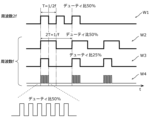
- FIG. 2 is a diagram showing voltage waveforms of control signal pulses applied to the transistor according to the first embodiment.
- FIG. 3 is a diagram showing a configuration of a battery monitoring system according to the second embodiment.
- FIG. 4 is a diagram showing a configuration of a battery monitoring system according to the third embodiment.
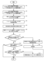
- FIG. 5 is a flowchart showing operations related to fault diagnosis and calibration in the battery monitoring system according to each embodiment.
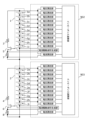
- FIG. 6 is a diagram showing the configuration of a conventional battery monitoring system.
- FIG. 7 is a diagram showing a configuration of a battery monitoring system in a comparative example.
- Fig. 6 is a diagram showing the configuration of a battery monitoring system in a conventional example.
- Fig. 7 is a diagram showing the configuration of a battery monitoring system in a comparative example.
- FIGS. 6 and 7 show a battery monitoring system for a battery pack in which 18 batteries, consisting of batteries 1a to 1i and batteries 2a to 2i, are connected in series.
- the battery monitoring system shown in FIG. 6 includes a first load resistor 3, a first transistor 5, and a first shunt resistor 7 as a circuit for measuring the AC impedance of the battery, and an impedance measurement integrated circuit 901 including multiple voltage measuring units and impedance calculation units as an integrated circuit for measuring the impedance.
- the battery monitoring system in FIG. 6 has one integrated circuit.
- the battery monitoring system in FIG. 7 has two integrated circuits.
- lithium-ion batteries are widely used as secondary batteries, but it is known that lithium-ion batteries deteriorate quickly due to overcharging, over-discharging, temperature, etc., and they are usually incorporated into a BMS and placed under appropriate control before use.
- Patent Document 1 proposes using the AC impedance method to measure the battery voltage and current.
- the inventors of the present application therefore conducted extensive research into a battery monitoring device and battery monitoring method that can suppress heat generation in the circuit that measures the battery's AC impedance, and have devised the battery monitoring device and battery monitoring method described below.
- the inventors of the present application have also devised a battery monitoring device and battery monitoring method that can reduce the size of the AC impedance measurement circuit for a battery pack in which multiple batteries are connected in series.
- the battery monitoring device includes a signal generating unit that generates a control signal to control a first measurement circuit to which the first assembled battery is connected and a second measurement circuit to which the second assembled battery is connected, among a first assembled battery and a second assembled battery that are obtained by dividing a plurality of batteries connected in series, and an impedance calculating unit that calculates the AC impedance of each of the plurality of batteries based on a first current value flowing through the first measurement circuit and a voltage value of each battery included in the first assembled battery, and a second current value flowing through the second measurement circuit and a voltage value of each battery included in the second assembled battery, which are measured at different times, and the first measurement circuit has a first switch connected in series with the first assembled battery, and the second measurement circuit has a second switch connected in series with the second assembled battery, and the signal generating unit generates the control signal to exclusively turn on the first switch and the second switch.
- the battery monitoring device can suppress heat generation in the circuit that measures the AC impedance of the battery.
- the battery monitoring device may be the battery monitoring device according to the first aspect, in which the first measurement circuit has a first transistor connected to the first assembled battery as the first switch, the second measurement circuit has a second transistor connected to the second assembled battery as the second switch, and the control signal is a signal for operating the first transistor and the second transistor in a time-division manner within independent periods.
- the timing of the impedance measurement can be easily made independent.
- the battery monitoring device may be the battery monitoring device according to the first or second aspect, in which the first control signal output to the first transistor and the second control signal output to the second transistor are rectangular wave signals that can be controlled to any period, and the signal generating unit may set a duty ratio of the first control signal according to the period of the first control signal, and set a duty ratio of the second control signal according to the period of the second control signal.
- the battery monitoring device is a battery monitoring device according to any one of the first to third aspects, and the first measurement circuit and the second measurement circuit may share some harnesses.
- a battery monitoring device may be the battery monitoring device according to the fourth aspect, in which the first measurement circuit has a first load resistor for measuring the AC impedance and a first shunt resistor for measuring current, which are connected to the first assembled battery, the second measurement circuit has a second load resistor for measuring the AC impedance and a second shunt resistor for measuring current, which are connected to the second assembled battery, and the common part of the harness may be arranged to connect the negative terminal of the first assembled battery and the positive terminal of the second assembled battery to the first load resistor and the second load resistor.
- the battery monitoring device is the battery monitoring device according to the fourth aspect, in which the first measurement circuit has the first assembled battery, a first load resistor for measuring the AC impedance and a first shunt resistor for measuring current, which are connected to the first assembled battery, and the second measurement circuit has the second assembled battery, a second load resistor for measuring the AC impedance and a second shunt resistor for measuring current, which are connected to the second assembled battery, and the first load resistor and the second load resistor may be provided in a common portion of the harness.
- the battery monitoring device may be the battery monitoring device according to the fifth or sixth aspect, further comprising an integrated circuit, and the integrated circuit may include a first current measurement unit that measures the current flowing through the first shunt resistor, a first voltage measurement unit that measures the voltage of each battery of the first assembled battery, a first impedance measurement calculation unit that calculates the AC impedance of each battery of the first assembled battery based on the current value measured by the first current measurement unit and the voltage value of each battery of the first assembled battery measured by the first voltage measurement unit, a second current measurement unit that measures the current flowing through the second shunt resistor, a second voltage measurement unit that measures the voltage of each battery of the second assembled battery, and a second impedance measurement calculation unit that calculates the AC impedance of each battery of the second assembled battery based on the current value measured by the second current measurement unit and the voltage value of each battery of the second assembled battery measured by the second voltage measurement unit.
- the integrated circuit may include a first current measurement unit that measures the current flowing through the first shunt resistor,
- the battery monitoring device can be realized using a single integrated circuit equipped with each function, making it possible to reduce the circuit size compared to when multiple integrated circuits are used.
- the battery monitoring device may be a battery monitoring device according to any one of the fifth to seventh aspects, in which the lowest battery of the first assembled battery and the highest battery of the second assembled battery are connected, the positive terminal of the highest battery of the first assembled battery is connected to the first shunt resistor, the first shunt resistor is connected to a first transistor which is the first switch, the negative terminal of the lowest battery of the second assembled battery is connected to the second shunt resistor, and the second shunt resistor is connected to a second transistor which is the second switch.
- the battery monitoring device may be a battery monitoring device according to any one of the first to eighth aspects, and the plurality of batteries may include one or more batteries included in both the first assembled battery and the second assembled battery.
- the battery monitoring device may be a battery monitoring device according to any one of the first to ninth aspects, in which the lowest battery of the first assembled battery and the highest battery of the second assembled battery are connected, and the battery monitoring device may include a calculation unit that performs at least one of determining a failure of the first measurement circuit and the second measurement circuit based on the AC impedance of the lowest battery of the first assembled battery and the AC impedance of the highest battery of the second assembled battery, and calibrating the measured AC impedance of each of the multiple batteries.
- the battery monitoring device may be a battery monitoring device according to any one of the first to tenth aspects, and may include a first calculation unit that estimates a first SOH of the first battery based on the AC impedance of an arbitrary first battery included in the first assembled battery, and estimates a second SOH of the second battery based on the AC impedance of an arbitrary second battery included in the second assembled battery, and a second calculation unit that performs at least one of determining a failure of the first measurement circuit and the second measurement circuit based on the third SOH of the first battery and the fourth SOH of the second battery estimated from a parameter other than the AC impedance, and the first SOH and the second SOH, and calibrating the measured AC impedance of each of the multiple batteries.
- the battery monitoring device may be the battery monitoring device according to any one of the first to 11th aspects, in which the lowest battery of the first assembled battery and the highest battery of the second assembled battery are connected, and the battery monitoring device may include a temperature measurement unit that measures the temperatures of the lowest battery and the highest battery based on the output of a first temperature sensor for measuring the temperature of the lowest battery of the first assembled battery and a second temperature sensor for measuring the temperature of the highest battery of the second assembled battery, and a battery state calculation unit that performs at least one of determining a failure of the first measurement circuit and the second measurement circuit based on the internal temperature of the lowest battery estimated from the AC impedance of the lowest battery of the first assembled battery and the respective temperatures of the highest battery and the lowest battery measured by the temperature measurement unit, and calibrating the measured AC impedance of each of the multiple batteries.
- the battery monitoring method generates a control signal to control a first measurement circuit to which the first assembled battery is connected and a second measurement circuit to which the second assembled battery is connected, among a first assembled battery and a second assembled battery that are obtained by dividing a plurality of batteries connected in series, and calculates the AC impedance of each of the plurality of batteries based on a first current value flowing through the first measurement circuit and a voltage value of each battery included in the first assembled battery, and a second current value flowing through the second measurement circuit and a voltage value of each battery included in the second assembled battery, which are measured at different times, the first measurement circuit has a first switch connected in series with the first assembled battery, and the second measurement circuit has a second switch connected in series with the second assembled battery, and in generating the control signal, the control signal is generated to exclusively turn on the first switch and the second switch.
- each figure is not necessarily a precise illustration.
- the same reference numerals are used for substantially the same configuration, and duplicate explanations are omitted or simplified.
- connection means an electrical connection, and includes not only the case where two circuit elements are directly connected, but also the case where two circuit elements are indirectly connected with another circuit element inserted between them.
- ordinal numbers such as “first” and “second” do not refer to the number or order of components, unless otherwise specified, but are used for the purpose of avoiding confusion between and distinguishing between components of the same type.
- FIG. 1 is a diagram showing the configuration of a battery monitoring system 301 according to the present embodiment.
- the battery monitoring system 301 is a system for monitoring (or controlling) an assembled battery in which secondary batteries such as lithium ion batteries are connected in series.
- the battery monitoring system 301 is a system for monitoring a first assembled battery 1 and a second assembled battery 2.
- the battery monitoring system 301 includes a battery monitoring device 201 having a first load resistor 3, a first transistor 5, and a first shunt resistor 7 connected in series with the first assembled battery 1, a second load resistor 4, a second transistor 6, and a second shunt resistor 8 connected in series with the second assembled battery 2, a first thermistor 19, a second thermistor 20, and an integrated circuit 101.
- the battery monitoring system 301 may further include an assembled battery (first assembled battery 1 and second assembled battery 2) to be monitored.
- the battery pack is composed of 18 batteries, batteries 1a-1i and batteries 2a-2i, connected in series.
- the first battery pack 1 includes one or more batteries, and in the example of FIG. 1, it includes nine batteries 1a-1i connected in series
- the second battery pack 2 includes one or more batteries, and in the example of FIG. 1, it includes nine batteries 2a-2i connected in series.
- the first battery pack 1 and the second battery pack 2 are connected in series to form one battery pack.
- Each of the batteries 1a-1i and batteries 2a-2i is a secondary battery configured to be chargeable and dischargeable, such as a lithium ion battery.
- the number of batteries included in each of the first assembled battery 1 and the second assembled battery 2 is not particularly limited, and may be different from each other, for example.
- the number of batteries included in the battery monitoring system 301 is also not particularly limited, and may be two or more.
- batteries 1a-1i and batteries 2a-2i may also be referred to as cells.
- the battery monitoring system 301 is configured to measure the voltage and current of the first assembled battery 1 and the second assembled battery 2 in a time-division manner.
- the first measuring circuit 1z is a circuit for measuring the AC impedance of each battery in the first assembled battery 1, and has a first load resistor 3, a first transistor 5, and a first shunt resistor 7 connected in series with the first assembled battery 1.
- a loop circuit is formed by the first load resistor 3, the first transistor 5, the first shunt resistor 7, and the first assembled battery 1.
- the first load resistor 3 is connected to the negative terminal of the first assembled battery 1 (the negative voltage terminal of battery 1i) and is a resistor for passing a current to measure the impedance of each battery in the first assembled battery 1.
- the first shunt resistor 7 is connected to the positive terminal of the first assembled battery 1 (the positive voltage terminal of battery 1a) and is a current measurement resistor for measuring the current flowing through the first measurement circuit 1z including the first assembled battery 1, and both ends are connected to the first current measurement unit 9.
- the first shunt resistor 7 is a resistor for measuring the current (pulse current) discharged from the first assembled battery 1 when the first transistor 5 is turned ON.
- the first transistor 5 is connected between the first load resistor 3 and the first shunt resistor 7, and is switched ON and OFF by a control signal generated by the first current drive waveform generating unit 11.
- the first transistor 5 is controlled by the control signal so as to switch at a frequency at which the impedance is measured.
- the first transistor 5 is a p-type transistor, but is not limited to this.
- the first transistor 5 is an example of a switch (first switch).
- the first measurement circuit 1z configured in this manner, heat is generated in the first load resistor 3 due to the total voltage of only batteries 1a to 1i out of batteries 1a to 1i and 2a to 2i. Because the voltage applied to the first load resistor 3 can be made lower than in the case of FIG. 6, the heat generated in the first load resistor 3 can be reduced.
- the arrangement order of the first load resistor 3, the first transistor 5, and the first shunt resistor 7 is not limited to the order shown in FIG. 1, and they may be connected in series between the positive terminal of the first assembled battery 1 and the negative terminal of the first assembled battery 1.
- the second measurement circuit 2z is a circuit for measuring the AC impedance of each battery in the second assembled battery 2, and has a second load resistor 4, a second transistor 6, and a second shunt resistor 8 connected in series with the second assembled battery 2.
- a loop circuit is formed by the second load resistor 4, the second transistor 6, the second shunt resistor 8, and the second assembled battery 2.
- the second load resistor 4 is connected to the positive terminal of the second assembled battery 2 (the positive voltage terminal of battery 2a) and is a resistor for passing a current to measure the impedance of each battery in the second assembled battery 2.
- the second shunt resistor 8 is connected to the negative terminal of the second assembled battery 2 (the negative voltage terminal of battery 2i) and is a current measurement resistor for measuring the current flowing through the second measurement circuit 2z including the second assembled battery 2, and both ends are connected to the second current measurement unit 10.
- the second shunt resistor 8 is a resistor for measuring the current (pulse current) discharged from the second assembled battery 2 when the second transistor 6 is turned ON.
- the second transistor 6 is connected between the second load resistor 4 and the second shunt resistor 8, and is switched ON and OFF by a control signal generated by the second current drive waveform generating unit 12.
- the second transistor 6 is controlled by the control signal so as to switch at a frequency at which the impedance is measured.
- the second transistor 6 is an n-type transistor, but is not limited to this.
- the second transistor 6 is an example of a switch (second switch).
- the arrangement order of the second load resistor 4, the second transistor 6, and the second shunt resistor 8 is not limited to the order shown in FIG. 1, and they may be connected in series between the positive terminal of the second assembled battery 2 and the negative terminal of the second assembled battery 2.
- the first switch and the second switch are not limited to being semiconductor switches, and may be switches other than semiconductor switches.
- the battery monitoring system 301 includes a common harness 30 that is used in common by the first measurement circuit 1z and the second measurement circuit 2z.
- the common harness 30 is arranged to connect the negative terminal of the first assembled battery 1 and the positive terminal of the second assembled battery 2 to the first load resistor 3 and the second load resistor 4. This makes it possible to reduce the size of the measurement circuit for an assembled battery in which multiple batteries are assembled using a single integrated circuit 101. Note that it is not essential to provide the common harness 30, and the first measurement circuit 1z and the second measurement circuit 2z may be formed with different wiring.
- the first thermistor 19 is disposed adjacent to the first assembled battery 1 and is a temperature sensor for measuring the temperature of the first assembled battery 1 (the temperature around the first assembled battery 1) during the period in which the impedance of the first assembled battery 1 is being measured.
- the first thermistor 19 is disposed adjacent to the battery 1i (lowest cell) in the first assembled battery 1 that is closest to the second assembled battery 2, and measures the temperature around that battery 1i.
- the first thermistor 19 may also be disposed at the voltage terminal of the lowest cell of the first assembled battery 1.
- the second thermistor 20 is disposed adjacent to the second assembled battery 2 and is a temperature sensor for measuring the temperature of the second assembled battery 2 (the temperature around the second assembled battery 2) during the period in which the impedance of the second assembled battery 2 is being measured.
- the second thermistor 20 is disposed adjacent to the battery 2a (top cell) in the second assembled battery 2 that is closest to the first assembled battery 1, and measures the temperature around that battery 2a.
- the second thermistor 20 may also be disposed at the voltage terminal of the top cell of the second assembled battery 2.
- batteries 1i and 2a are adjacent batteries, the first thermistor 19 and the second thermistor 20 are positioned close to each other. Therefore, if the elements of batteries 1i and 2a or the first measuring circuit 1z and the second measuring circuit 2z are normal, it is believed that the temperature measured by the first thermistor 19 and the temperature measured by the second thermistor 20 will be close to each other.
- the temperature sensor provided in the battery monitoring system 301 is not limited to being a thermistor, and may be, for example, a temperature sensor using other elements such as a thermocouple.
- the integrated circuit 101 includes a first current measurement unit 9, a second current measurement unit 10, a first current drive waveform generation unit 11, a second current drive waveform generation unit 12, a voltage measurement unit 13, an SOC (State of Charge) calculation unit 14, an impedance calculation unit 15, a battery state calculation unit 16, a temperature measurement unit 17, and a memory unit 18.
- the integrated circuit 101 includes a processor and a memory.
- the memory is a ROM (Read Only Memory) and a RAM (Random Access Memory), etc., and can store a program executed by the processor.
- the first current measurement unit 9, the second current measurement unit 10, the first current drive waveform generation unit 11, the second current drive waveform generation unit 12, the voltage measurement unit 13, the SOC calculation unit 14, the impedance calculation unit 15, the battery state calculation unit 16, and the temperature measurement unit 17 are realized by a processor that executes a program stored in a memory. Also, for example, each of the above functions is realized by one integrated circuit 101.
- the first current measuring unit 9 measures the current flowing through the first measuring circuit 1z including the first assembled battery 1.
- the first current measuring unit 9 may have an ADC (Analog Digital Converter) unit that converts an analog signal value corresponding to the current of the first assembled battery 1 into a digital signal value, and a calculation unit that calculates the current value by processing the digital signal value that is the output of the ADC unit.
- ADC Analog Digital Converter
- the first current measuring unit 9 is a resistance detection type current sensor that uses the first shunt resistor 7, but may also be a magnetic field detection type current sensor.
- the second current measuring unit 10 measures the current flowing through the second measuring circuit 2z including the second assembled battery 2.
- the second current measuring unit 10 may have an ADC unit that converts an analog signal value corresponding to the current of the second assembled battery 2 into a digital signal value, and a calculation unit that calculates the current value by processing the digital signal value that is the output of the ADC unit.
- the second current measuring unit 10 is a resistance detection type current sensor that uses the second shunt resistor 8, but may also be a magnetic field detection type current sensor.
- the first current drive waveform generating unit 11 generates a control signal for controlling ON and OFF of the first transistor 5, and outputs it to the first transistor 5.
- the control signal is, for example, a rectangular wave signal that can be controlled to any period, and is input to the gate electrode of the first transistor 5.
- the control signal is a control signal that has multiple frequency components.
- the second current drive waveform generating unit 12 generates a control signal for controlling ON and OFF of the second transistor 6, and outputs it to the second transistor 6.
- the control signal is, for example, a rectangular wave signal that can be controlled to any period, and is input to the gate electrode of the second transistor 6.
- the control signal is also a control signal having multiple frequency components.
- the multiple frequency components here may be, for example, the same frequency components as the multiple frequency components of the control signal generated by the first current drive waveform generating unit 11.
- the first current drive waveform generating unit 11 and the second current drive waveform generating unit 12 generate control signals so that only one of the first transistor 5 and the second transistor 6 is ON.
- the control signals are signals for operating the first transistor 5 and the second transistor 6 in a time-division manner within independent periods. It can also be said that the first current drive waveform generating unit 11 and the second current drive waveform generating unit 12 generate control signals for exclusively turning on the first transistor 5 and the second transistor 6. In this way, the control signals control the period in which the first transistor 5 is ON and the period in which the second transistor 6 is ON so that they do not overlap in time.
- the first current drive waveform generating unit 11 and the second current drive waveform generating unit 12 are examples of a signal generating unit.
- the period during which the first transistor 5 is ON and the period during which the second transistor 6 is ON are not limited to being completely non-overlapping in time, and may be only partially overlapping.
- FIG. 2 is a diagram showing the voltage waveforms of the control signal pulses applied to the transistor in this embodiment.
- FIG. 2 illustrates the voltage waveforms of four control signals (control signals w1 to w4) generated by the first current drive waveform generating unit 11 and the second current drive waveform generating unit 12.
- the control signal w1 has a frequency of 2f and a voltage waveform with a duty ratio of 50%.
- Control signal w2 has a frequency f and shows a voltage waveform with a duty ratio of 50%.
- control signal w3 with a duty ratio of 25% instead of 50%.
- control signal w4 with an even higher duty ratio of 50% within the pulse during the ON period may be used.
- the first current drive waveform generating unit 11 sets the duty ratio of the first control signal according to the period of the first control signal
- the second current drive waveform generating unit 12 sets the duty ratio of the second control signal according to the period of the second control signal.
- the first current drive waveform generating unit 11 and the second current drive waveform generating unit 12 set the duty ratio of the control signal with a frequency of f or more and 2f or less so that the difference between the amount of heat generated at a reference frequency set in a predetermined frequency band (for example, a frequency of f or more and 2f or less) and the amount of heat generated at other frequencies of f or more and 2f or less is equal to or less than a predetermined value.
- the first current drive waveform generating unit 11 and the second current drive waveform generating unit 12 may set the duty ratio to be smaller as the frequency decreases and larger as the frequency increases.
- a table in which frequencies and duty ratios are associated is stored in the storage unit 18, and the first current drive waveform generating unit 11 and the second current drive waveform generating unit 12 may use the table to switch the duty ratio for each frequency.
- the reference frequency may be a frequency that is higher than a predetermined frequency (e.g., the highest) within the frequency band.
- a predetermined frequency e.g., the highest
- the reference frequency may be frequency 2f.
- the reference frequency may be a frequency at which the amount of heat generated is lower than a predetermined value (e.g., the smallest) when the duty ratio is the same within the frequency band.
- a control signal (a control signal of a constant voltage) that turns the second transistor 6 OFF may be applied.
- a voltage measurement unit 13 is provided for each battery, and measures the voltage of the connected battery.
- the voltage measurement unit 13 may have an ADC unit that converts an analog signal value corresponding to the battery voltage into a digital signal value, and a calculation unit that processes the digital signal value that is the output of the ADC unit to calculate a voltage value.
- the SOC calculation unit 14 measures the SOC of the battery pack.
- the SOC calculation unit 14 may acquire the current and voltage of the battery pack or of each of the batteries 1a to 2i that make up the battery pack, and calculate the SOC by Coulomb counting or estimation from the SOC-OCV (Open Circuit Voltage) curve.
- SOC-OCV Open Circuit Voltage
- the impedance calculation unit 15 calculates the AC impedance of each of the multiple batteries 1a-1i and batteries 2a-2i from the AC voltage and AC current obtained by measuring the first assembled battery 1 and the second assembled battery 2.
- the impedance calculation unit 15 measures the current I1 flowing through the first shunt resistor 7 and the voltage Vn1 of each battery in the first assembled battery 1, which are obtained by applying a control signal having multiple frequency components to the control terminal of the first transistor 5.
- the impedance calculation unit 15 also measures the current I2 flowing through the second shunt resistor 8 and the voltage Vn2 of each battery in the second assembled battery 2, which are obtained by applying a control signal having multiple frequency components to the control terminal of the second transistor 6.
- the impedance calculation unit 15 converts the measured currents I1 and I2 into complex currents, and converts the measured voltages Vn1 and Vn2 into complex voltages. After that, the impedance calculation unit 15 averages the complex currents and the complex voltages.
- the impedance calculation unit 15 calculates the AC impedance of each battery by dividing the complex voltage after averaging by the complex current after averaging.
- Each AC impedance is a complex number (complex impedance) and has a real component Re and an imaginary component Im. Note that hereinafter, AC impedance may also be simply referred to as impedance.
- the battery state calculation unit 16 estimates at least one of the SOH (State of Health: capacity maintenance rate) and the internal temperature, which indicate the deterioration state of the battery, from the calculation results of the impedance calculation unit 15.
- SOH State of Health: capacity maintenance rate
- the battery state calculation unit 16 may estimate the current full charge capacity of the battery from the first correspondence relationship and the current AC impedance, and calculate the SOH (%) by dividing the estimated current full charge capacity by the initial full charge capacity and multiplying the result by 100.
- the initial full charge capacity and the first correspondence relationship may be stored in the memory unit 18.
- the first correspondence relationship may be, for example, a table in which the AC impedance and the full charge capacity of the battery are associated.
- the battery state calculation unit 16 may estimate the current internal temperature of the battery from the second correspondence relationship and the current AC impedance.
- the second correspondence relationship may be stored in the memory unit 18.
- the second correspondence relationship may be, for example, a table in which the AC impedance and the internal temperature of the battery are associated.
- the method for estimating the SOH and internal temperature is not limited to the above, and any known method may be used.
- the temperature measurement unit 17 measures the temperature of the battery pack.
- the temperature measurement unit 17 is connected to a first thermistor 19 adjacent to the first battery pack 1 and a second thermistor 20 adjacent to the second battery pack 2, and measures the temperatures around the first thermistor 19 and the second thermistor 20. In this embodiment, the temperature measurement unit 17 measures the temperatures near the battery 1i and near the battery 2a.
- the memory unit 18 is a storage device that stores various information and various programs for estimating the battery state.
- the memory unit 18 is realized, for example, by a HDD (Hard Disk Drive) or a semiconductor memory.
- the integrated circuit 101 may also include a diagnostic calibration unit (e.g., the diagnostic calibration unit 21 shown in FIG. 3, which will be described later) that performs fault diagnosis and impedance calibration.
- a diagnostic calibration unit e.g., the diagnostic calibration unit 21 shown in FIG. 3, which will be described later.
- FIG. 3 is a diagram showing the configuration of a battery monitoring system 301 according to the present embodiment.
- the battery monitoring system 301 according to the present embodiment differs from the battery monitoring system 301 according to the first embodiment mainly in that the load resistor (third load resistor 22) is a resistor common to the first measurement circuit 1z and the second measurement circuit 2z.
- the differences from the first embodiment will be mainly described, and the description of the same or similar contents as the first embodiment will be omitted or simplified. For convenience, the same or similar configurations as the first embodiment will be described using the symbols of the first embodiment.
- the battery monitoring system 301 includes a third load resistor 22 in place of the first load resistor 3 and the second load resistor 4 shown in FIG. 1, and further includes a diagnostic calibration unit 21.
- the third load resistor 22 is provided in the common harness 30. One end of the third load resistor 22 is connected to the negative terminal of the first assembled battery 1 and the positive terminal of the second assembled battery 2, and the other end is connected to the first transistor 5 and the second transistor 6. This makes it possible to reduce the number of load resistors, and therefore the size of the measurement circuit.
- the diagnostic calibration unit 21 diagnoses (determines) whether or not the measurement circuit (e.g., an element of the measurement circuit) is faulty based on the AC impedance, and also calibrates the impedance.
- the diagnostic calibration unit 21 will be described later with reference to FIG. 5.
- the number of batteries contained in the first assembled battery 1 and the number of batteries contained in the second assembled battery 2 are the same, but may be different as long as the measurement accuracy is within a range that satisfies the desired accuracy.
- FIG. 4 is a diagram showing the configuration of a battery monitoring system 301 according to this embodiment.
- the battery monitoring system 301 according to this embodiment differs from the battery monitoring system 301 according to embodiment 1 in that the battery 12a is included in each of the first assembled battery 1 and the second assembled battery 2.
- the differences from embodiment 1 will be mainly described, and descriptions of contents that are the same as or similar to embodiment 1 will be omitted or simplified. For convenience, the same or similar configurations as embodiment 1 will be described using the symbols of embodiment 1.
- a first load resistor 3 is connected to the negative terminal of the lowest cell of the first assembled battery 1 and a highest cell of the second assembled battery 2 so that the cell is the same as the lowest cell of the first assembled battery 1, and a second load resistor 4 is connected to the positive terminal of the same cell.
- the first assembled battery 1 includes nine batteries including batteries 1a-1h and common battery 12a
- the second assembled battery 2 includes ten batteries including batteries 2a-2i and common battery 12a. Note that the number of batteries is not limited to this, and for example, the first assembled battery 1 and the second assembled battery 2 may have the same number.
- the voltage of battery 12a is measured when the first assembled battery 1 is measured and when the second assembled battery 2 is measured.
- the voltage measurement result (voltage value) of battery 12a when the first assembled battery 1 is measured and the voltage measurement result (voltage value) of battery 12a when the second assembled battery 2 is measured should be the same voltage value, and because the two voltage values are different, it is possible to determine whether any element of the measurement circuit (e.g., at least one of the first load resistor 3, the second load resistor 4, the first transistor 5, the second transistor 6, the first shunt resistor 7, and the second shunt resistor 8) is faulty.
- the battery monitoring system 301 according to this embodiment can perform fault diagnosis of the measurement circuit.
- this determination may be made, for example, using the current and past voltage values of the battery 12a in the first assembled battery 1 or the second assembled battery 2. In other words, it may be possible to determine whether or not the battery 12a has deteriorated over time.
- the first thermistor 19 is placed near the commonly included battery 12a.
- the number of batteries commonly included in the first assembled battery 1 and the second assembled battery 2 is not limited to one, and may be multiple.
- FIG. 5 is a flowchart showing the operation related to the fault diagnosis and calibration (battery monitoring method) in the battery monitoring system 301 according to each of the embodiments.
- the battery monitoring device 201 controls the lower EIS (Electro-chemical Impedance Spectroscopy) measurement circuit (second measurement circuit 2z) to measure the AC voltage and AC current of the lower assembled battery group (second assembled battery 2), and further measures the second thermistor temperature (S1).
- the second thermistor temperature is a temperature measured using the second thermistor 20.
- the battery monitoring device 201 measures the AC voltage and AC current of the second assembled battery 2 by turning off the first transistor 5 and turning on the second transistor 6. Note that turning on the second transistor 6 means switching the second transistor 6 at a frequency for measuring impedance using a control signal such as that shown in FIG. 2.
- the battery monitoring device 201 controls the upper EIS measurement circuit (first measurement circuit 1z) to measure the AC voltage and AC current of the upper battery pack (first battery pack 1), and further measures the first thermistor temperature (S2).
- the first thermistor temperature is a temperature measured using the first thermistor 19.
- the battery monitoring device 201 measures the AC voltage and AC current of the first battery pack 1 by turning on the first transistor 5 and turning off the second transistor 6.
- the measurements of the first measurement circuit 1z and the second measurement circuit 2z are performed at different timings in a time-division manner.
- the impedance calculation unit 15 calculates the measured AC voltage and AC current into impedance (AC impedance) (S3).
- the battery state calculation unit 16 estimates the first SOH and the internal temperature from the impedance calculated by the impedance calculation unit 15 (S4).
- the battery state calculation unit 16 stores the measurement results and the estimation results in the memory unit 18 (S5).
- the memory unit 18 stores the measurement values measured in steps S1 and S2 and the estimated values estimated in step S4.
- the battery state calculation unit 16 estimates the second SOH using the time-sampled current data and voltage data (S6).
- the battery state calculation unit 16 estimates the second SOH based on the time response of the current and voltage when the battery is discharged under a constant frequency condition.
- the voltage of each battery of the first assembled battery 1 and the second assembled battery 2 is sampled using the voltage measurement unit 13
- the current is sampled using the first current measurement unit 9
- the current is sampled using the second current measurement unit 10.
- the measurements (time sampling) of the first measurement circuit 1z and the second measurement circuit 2z may be performed at different times in a time-division manner.
- the battery state calculation unit 16 determines whether the difference between values (e.g., estimated values) relating to adjacent or common cells is equal to or less than a threshold value (S7).
- the value relating to adjacent or common cells may be the measured impedance itself, or may be a value indicating the battery state, such as SOH or internal temperature. Below, an example in which the value indicates the battery state is described.
- the battery state calculation unit 16 determines whether the difference in SOH or internal temperature between adjacent batteries (e.g., batteries 1i and 2a) is equal to or less than a threshold value.
- the battery state calculation unit 16 performs at least one of the following: comparing the first SOH of battery 1i estimated in step S4 with the first SOH of battery 2a, and comparing the second SOH of battery 1i estimated in step S6 with the second SOH of battery 2a, and determines whether the difference in SOH is equal to or less than a threshold value.
- the battery state calculation unit 16 determines whether the difference in SOH or internal temperature of the common cell (e.g., battery 12a) is equal to or less than a threshold value.
- the battery state calculation unit 16 performs at least one of the following: comparing the first SOH of battery 12a when measured by the first measurement circuit 1z with the first SOH of battery 12a when measured by the second measurement circuit 2z, and comparing the second SOH of battery 12a when measured by the first measurement circuit 1z with the second SOH of battery 12a when measured by the second measurement circuit 2z, and determines whether the difference in SOH is equal to or less than a threshold value.
- step S7 becomes greater than the threshold value. Note that although it is possible to determine at this point whether or not there is a fault, if there is a fault, it is not possible to identify which of the measurement circuit's elements is faulty.
- the threshold value is preset and stored in the memory unit 18.
- the determination in step S7 may be made, for example, based on whether the difference between the first SOH of the battery (for example, battery 1i in the first measurement circuit 1z) estimated in step S4 and the second SOH of the battery estimated in step S6 is equal to or less than a threshold value. In this case, the determination is made in each of the first measurement circuit 1z and the second measurement circuit 2z.
- the diagnostic calibration unit 21 reads the reference value of the value from the memory unit 18 and compares it to identify the faulty circuit (S8). To identify which of the elements in the first measurement circuit 1z and the second measurement circuit 2z is faulty, the diagnostic calibration unit 21 reads the reference value of SOH, which is an example of a value, from the memory unit 18, and based on the reference value and the SOH of the adjacent battery, identifies, for example, the measurement circuit including the battery with the larger difference from the reference value as the faulty circuit.
- SOH is an example of a value
- the diagnostic calibration unit 21 performs a fault notification (S9).
- the diagnostic calibration unit 21 transmits information indicating the identified faulty circuit to a terminal device of a user (e.g., the manager of the battery pack).
- the diagnostic calibration unit 21 further determines whether or not there is a common cell configuration (S10).
- a common cell configuration means that the two measurement circuits have a common cell (battery 12a) as shown in FIG. 4.
- Information indicating whether or not there is a common cell configuration may be stored in the memory unit 18, for example. Note that if the difference between the values is equal to or less than the threshold value, it means that the measurement circuit is not faulty.
- the diagnostic calibration unit 21 determines that the cell configuration is common (Yes in S10), it further reads the reference value from the memory unit 18 and compares it to determine whether it is below the threshold value (S11).
- the diagnostic calibration unit 21 compares the SOH or internal temperature of the common cell (battery 12a in the example of FIG. 4) with the reference value and determines whether the difference is below the threshold value.
- the threshold value here may be the same value as the threshold value in step S7, or may be a mutually different value.
- the diagnostic calibration unit 21 determines that the difference is equal to or less than the threshold value in the common cell configuration (Yes in S11), or if it determines that the common cell configuration is not present (No in S10), the process ends.
- the diagnostic calibration unit 21 determines that the difference is not equal to or less than the threshold value in the common cell configuration, that is, if there is a difference between the estimated value and the reference value that is greater than the threshold value (No in S11), it calibrates the impedance calculation based on the reference value (S12).
- the diagnostic calibration unit 21 determines that the impedance measurement accuracy has decreased due to an external factor (e.g., the influence of a magnetic field from an external circuit), and calibrates the impedance calculated in step S3. Calibration here means bringing the impedance calculated in step S3 closer to the true value based on the reference value.
- the diagnostic calibration unit 21 calibrates the impedance stored in the memory unit 18 based on a reference value, and stores the calibrated impedance in the memory unit 18.
- the diagnostic calibration unit 21 may replace the impedance calculated in step S3 with a reference value, may replace it with a statistical value of the impedance obtained in multiple past measurements, or may multiply the impedance calculated in step S3 by a coefficient based on the reference value.
- the statistical value is an average value, but may also be, for example, a median.
- the battery monitoring device 201 and battery monitoring system 301 can be used as a battery monitoring device and BMS that monitor batteries such as a battery pack in which cells such as lithium ion batteries are connected in series.
- the battery monitoring device 201 and battery monitoring system 301 can be used as a small battery monitoring device that can measure the impedance of a battery, for example, as a battery monitoring device that monitors environmentally friendly vehicles such as electric vehicles, storage batteries for a stable supply of renewable energy, and the like.
- each component may be configured with dedicated hardware, or may be realized by executing a software program suitable for each component.
- Each component may be realized by a program execution unit such as a CPU or processor reading and executing a software program recorded on a recording medium such as a hard disk or semiconductor memory.
- the division of functional blocks in the block diagram is one example, and multiple functional blocks may be realized as one functional block, one functional block may be divided into multiple blocks, or some functions may be transferred to other functional blocks. Furthermore, the functions of multiple functional blocks having similar functions may be processed in parallel or in a time-sharing manner by a single piece of hardware or software.
- the battery monitoring device 201 may be realized as a single device, or may be realized by multiple devices.
- the components of the battery monitoring device 201 may be distributed in any manner among the multiple devices.
- the communication method between the multiple devices is not particularly limited, and may be wireless communication or wired communication. Furthermore, wireless communication and wired communication may be combined between the devices.
- each component described in each of the above embodiments may be realized as software, or may be realized as an LSI, which is typically an integrated circuit. These may be individually integrated into one chip, or may be integrated into one chip that includes some or all of them.
- LSI is used, but depending on the degree of integration, it may be called IC, system LSI, super LSI, or ultra LSI.
- the method of integration is not limited to LSI, and may be realized with a dedicated circuit (a general-purpose circuit that executes a dedicated program) or a general-purpose processor.
- a programmable FPGA Field Programmable Gate Array
- a reconfigurable processor that can reconfigure the connection or settings of circuit cells inside the LSI may be used.
- an integrated circuit technology that replaces LSI appears due to advances in semiconductor technology or a different derived technology, it is natural that the components may be integrated using that technology.
- a system LSI is an ultra-multifunctional LSI manufactured by integrating multiple processing units on a single chip, and is specifically a computer system that includes a microprocessor, ROM, RAM, etc. Computer programs are stored in the ROM. The system LSI achieves its functions when the microprocessor operates according to the computer program.
- An aspect of the present disclosure may be a computer program that causes a computer to execute each of the characteristic steps included in the battery monitoring method shown in FIG. 5.
- the program may be a program to be executed by a computer.
- one aspect of the present disclosure may be a non-transitory computer-readable recording medium on which such a program is recorded.
- such a program may be recorded on a recording medium and distributed or circulated.
- the distributed program may be installed in a device having another processor, and the program may be executed by that processor, thereby making it possible to cause that device to perform each of the above processes.
- This disclosure is useful for battery monitoring devices that monitor batteries such as battery packs.
Landscapes
- Engineering & Computer Science (AREA)
- Physics & Mathematics (AREA)
- General Physics & Mathematics (AREA)
- Power Engineering (AREA)
- Manufacturing & Machinery (AREA)
- Chemical & Material Sciences (AREA)
- Chemical Kinetics & Catalysis (AREA)
- Electrochemistry (AREA)
- General Chemical & Material Sciences (AREA)
- Charge And Discharge Circuits For Batteries Or The Like (AREA)
Abstract
電池監視装置(201)は、直列に接続された複数の電池を分割した第一組電池(1)が接続される第一測定回路(1z)、及び、複数の電池を分割した第二組電池(2)が接続される第二測定回路(2z)を制御する制御信号を生成する信号生成部と、測定された、第一測定回路(1z)を流れる電流値及び第一組電池(1)に含まれる各電池の電圧値と、第二測定回路(2z)を流れる電流値及び第二組電池(2)に含まれる各電池の電圧値とに基づいて、複数の電池それぞれの交流インピーダンスを演算するインピーダンス演算部(15)とを備え、第一測定回路(1z)は、第一スイッチを有し、第二測定回路(2z)は、第二スイッチを有し、信号生成部は、第一スイッチ及び第二スイッチを排他的にオンさせるための制御信号を生成する。
Description
本開示は、電池監視装置及び電池監視方法に関する。
近年、電気自動車をはじめとする環境対応車、再生可能エネルギーを安定供給させるための蓄電池など、二次電池を使用したアプリケーションが急増している。エネルギー密度が高いことから、二次電池としてリチウムイオン電池(LiB:Lithium-ion Battery)を採用することが多い。リチウムイオン電池は、過充電、過放電、温度などによって劣化が加速することが知られており、最悪のケースでは発煙発火、さらには爆発の危険な状態に至ることもあるため、通常はバッテリマネジメントシステム(BMS:Battery Management System)に組み込まれて適切な制御下に置かれて使用される。
最近では、電池の交流インピーダンスを測定することで、電池の劣化又は内部温度を検出して電池制御の精度を向上させる検討がなされている。例えば、特許文献1には、組電池の各電池に交流信号を掃引させながら電圧及び電流を測定する交流インピーダンス法を用いることが開示されている。
しかしながら、特許文献1の方法では、電池の交流インピーダンスを測定する回路が発熱するという課題がある。
そこで、本開示は、電池の交流インピーダンスを測定する回路の発熱を抑制することができる電池監視装置及び電池監視方法を提供する。
本開示の一態様に係る電池監視装置は、直列に接続された複数の電池を分割した第一組電池及び第二組電池のうち前記第一組電池が接続される第一測定回路、及び、前記第二組電池が接続される第二測定回路を制御する制御信号を生成する信号生成部と、互いに異なるタイミングで測定された、前記第一測定回路を流れる第一電流値及び前記第一組電池に含まれる各電池の電圧値と、前記第二測定回路を流れる第二電流値及び前記第二組電池に含まれる各電池の電圧値とに基づいて、前記複数の電池それぞれの交流インピーダンスを演算するインピーダンス演算部とを備え、前記第一測定回路は、前記第一組電池と直列に接続された第一スイッチを有し、前記第二測定回路は、前記第二組電池と直列に接続された第二スイッチを有し、前記信号生成部は、前記第一スイッチ及び前記第二スイッチを排他的にオンさせるための前記制御信号を生成する。
本開示の一態様に係る電池監視方法は、直列に接続された複数の電池を分割した第一組電池及び第二組電池のうち前記第一組電池が接続される第一測定回路、及び、前記第二組電池が接続される第二測定回路を制御する制御信号を生成し、互いに異なるタイミングで測定された、前記第一測定回路を流れる第一電流値及び前記第一組電池に含まれる各電池の電圧値と、前記第二測定回路を流れる第二電流値及び前記第二組電池に含まれる各電池の電圧値とに基づいて、前記複数の電池それぞれの交流インピーダンスを演算し、前記第一測定回路は、前記第一組電池と直列に接続された第一スイッチを有し、前記第二測定回路は、前記第二組電池と直列に接続された第二スイッチを有し、前記制御信号の生成では、前記第一スイッチ及び前記第二スイッチを排他的にオンさせるための前記制御信号を生成する。
本開示の一態様によれば、電池の交流インピーダンスを測定する回路の発熱を抑制することができる電池監視装置等を実現することができる。
(本開示に至った経緯)
本開示の説明に先立ち、本開示に至った経緯について、図6及び図7を参照しながら説明する。図6は、従来例における電池監視システムの構成を示す図である。図7は、比較例における電池監視システムの構成を示す図である。
本開示の説明に先立ち、本開示に至った経緯について、図6及び図7を参照しながら説明する。図6は、従来例における電池監視システムの構成を示す図である。図7は、比較例における電池監視システムの構成を示す図である。
図6及び図7では、電池1a~1iと、電池2a~2iとから構成される18個の電池が直列に接続された組電池における電池監視システムを示している。図6に示す電池監視システムは、電池の交流インピーダンスを測定する回路として、第一負荷抵抗3、第一トランジスタ5及び第一シャント抵抗7を備え、インピーダンスを測定する集積回路として複数の電圧測定部及びインピーダンス演算部等を含むインピーダンス測定集積回路901を備える。つまり、図6の電池監視システムは、1つの集積回路を有する。また、図7に示す電池監視システムは、第一組電池1の交流インピーダンスを測定する回路として、第一負荷抵抗3、第一トランジスタ5及び第一シャント抵抗7を備え、インピーダンスを測定する集積回路として複数の電圧測定部及びインピーダンス演算部等を含むインピーダンス測定集積回路902を備え、第二組電池2の複素インピーダンスを測定する回路として、第二負荷抵抗4、第二トランジスタ6及び第二シャント抵抗8を備え、インピーダンスを測定する集積回路として複数の電圧測定部及びインピーダンス演算部等を含むインピーダンス測定集積回路903を備える。つまり、図7の電池監視システムは、2つの集積回路を有する。
上記の「背景技術」でも記載したように、二次電池としてリチウムイオン電池が多く採用されているが、リチウムイオン電池は、過充電、過放電、温度などによって劣化が加速することが知られており、通常はBMSに組み込まれて適切な制御下に置かれて使用される。
電池の劣化、内部温度などを検出して電池制御の精度を向上させるために、例えば特許文献1には、電池の電圧及び電流を測定する交流インピーダンス法を用いることが提案されている。
しかしながら、特許文献1で提案されるインピーダンス測定回路は多直列に組まれた複数の電池のインピーダンスを測定する場合(例えば、図6を参照)、複数の電池の総電圧とインピーダンス測定電流とから生じる熱が第一負荷抵抗3に発生する。そのため、測定で発生した熱量を放熱する必要が生じ、例えばファンなど放熱する機能の追加あるいは第一負荷抵抗3を並列に実装し負荷抵抗で発生する熱を分散させる必要があり、回路規模が増加してしまう。
また、図7に示すような構成を考えると、第一負荷抵抗3及び第二負荷抵抗4の発熱を低減することは可能であるが、必要な集積回路の数だけインピーダンス測定回路のハーネスが必要となる。したがって、電池の直列数の増加に伴い、スケーラブルに回路規模が増加してしまう。つまり、図7に示す比較例では、発熱の抑制と回路規模の削減とを両立することは困難である。
そこで、本願発明者らは、電池の交流インピーダンスを測定する回路の発熱を抑制することができる電池監視装置及び電池監視方法について鋭意検討を行い、以下に示す電池監視装置及び電池監視方法を創案した。また、本願発明者らは、さらに多数の電池が直列に組まれた組電池の交流インピーダンス測定回路の規模を削減することができる電池監視装置及び電池監視方法を創案した。
本開示の第1態様に係る電池監視装置は、直列に接続された複数の電池を分割した第一組電池及び第二組電池のうち前記第一組電池が接続される第一測定回路、及び、前記第二組電池が接続される第二測定回路を制御する制御信号を生成する信号生成部と、互いに異なるタイミングで測定された、前記第一測定回路を流れる第一電流値及び前記第一組電池に含まれる各電池の電圧値と、前記第二測定回路を流れる第二電流値及び前記第二組電池に含まれる各電池の電圧値とに基づいて、前記複数の電池それぞれの交流インピーダンスを演算するインピーダンス演算部とを備え、前記第一測定回路は、前記第一組電池と直列に接続された第一スイッチを有し、前記第二測定回路は、前記第二組電池と直列に接続された第二スイッチを有し、前記信号生成部は、前記第一スイッチ及び前記第二スイッチを排他的にオンさせるための前記制御信号を生成する。
これにより、第一組電池及び第二組電池のインピーダンス測定のタイミングを独立させる(異ならせる)ことができ、その結果発熱する時間が分散されるので負荷抵抗での発熱を抑制することができる。よって、電池監視装置によれば、電池の交流インピーダンスを測定する回路の発熱を抑制することができる。
また、例えば、第2態様に係る電池監視装置は、第1態様に係る電池監視装置であって、前記第一測定回路は、前記第一スイッチとして、前記第一組電池に接続された第一トランジスタを有し、前記第二測定回路は、前記第二スイッチとして、前記第二組電池に接続された第二トランジスタを有し、前記制御信号は、前記第一トランジスタ及び前記第二トランジスタのそれぞれを独立した期間内に時分割で動作させるための信号であってもよい。
これにより、第一トランジスタ及び第二トランジスタを用いるので、インピーダンス測定のタイミングを容易に独立させることができる。
また、例えば、第3態様に係る電池監視装置は、第1態様又は第2態様に係る電池監視装置であって、前記第一トランジスタに出力される第一制御信号、及び、前記第二トランジスタに出力される第二制御信号は、任意の周期に制御可能な矩形波信号であり、前記信号生成部は、前記第一制御信号の周期に応じた当該第一制御信号のデューティ比を設定し、前記第二制御信号の周期に応じた当該第二制御信号のデューティ比を設定してもよい。
これにより、制御信号の周波数を変化(例えば、掃引)させた場合に、負荷抵抗での発熱が周波数により変化することを抑制することができる。また、例えば、発熱量が小さくなるようにデューティ比が設定されることで、発熱量自体を減らすことが可能である。
また、例えば、第4態様に係る電池監視装置は、第1態様~第3態様のいずれか1つの態様に係る電池監視装置であって、前記第一測定回路と前記第二測定回路とは、一部のハーネスが共通であってもよい。
これにより、第一測定回路及び第二測定回路を構成するためのハーネス数を減らすことができる。よって、発熱の抑制と回路規模の削減とを両立することができる。
また、例えば、第5態様に係る電池監視装置は、第4態様に係る電池監視装置であって、前記第一測定回路は、前記第一組電池に接続された、前記交流インピーダンスを測定するための第一負荷抵抗及び電流測定用の第一シャント抵抗を有し、前記第二測定回路は、前記第二組電池に接続された、前記交流インピーダンスを測定するための第二負荷抵抗及び電流測定用の第二シャント抵抗を有し、共通である前記一部のハーネスは、前記第一組電池の負端子及び前記第二組電池の正端子と、前記第一負荷抵抗及び前記第二負荷抵抗とを接続するように配置されてもよい。
これにより、第一組電池の負端子及び第二組電池の正端子と、第一負荷抵抗及び第二負荷抵抗とを接続するためのハーネスの数を減らすことができる。
また、例えば、第6態様に係る電池監視装置は、第4態様に係る電池監視装置であって、前記第一測定回路は、前記第一組電池と、前記第一組電池と接続された、前記交流インピーダンスを測定するための第一負荷抵抗及び電流測定用の第一シャント抵抗とを有し、前記第二測定回路は、前記第二組電池と、前記第二組電池と接続された、前記交流インピーダンスを測定するための第二負荷抵抗及び電流測定用の第二シャント抵抗とを有し、前記第一負荷抵抗及び前記第二負荷抵抗は、共通である前記一部のハーネスに設けられてもよい。
これにより、第一測定回路及び第二測定回路の負荷抵抗を共通化することができるので、さらに回路規模を削減することができる。
また、例えば、第7態様に係る電池監視装置は、第5態様又は第6態様に係る電池監視装置であって、さらに、集積回路を備え、前記集積回路は、前記第一シャント抵抗に流れる電流を測定する第一電流測定部と、前記第一組電池の各電池の電圧を測定する第一電圧測定部と、前記第一電流測定部により測定された電流値、及び、前記第一電圧測定部により測定された前記第一組電池の各電池の電圧値に基づいて、前記第一組電池の各電池の交流インピーダンスを演算する第一インピーダンス測定演算部と、前記第二シャント抵抗に流れる電流を測定する第二電流測定部と、前記第二組電池の各電池の電圧を測定する第二電圧測定部と、前記第二電流測定部により測定された電流値、及び、前記第二電圧測定部により測定された前記第二組電池の各電池の電圧値に基づいて、前記第二組電池の各電池の交流インピーダンスを演算する第二インピーダンス測定演算部とを備えてもよい。
これにより、各機能を備えた1つの集積回路により電池監視装置を実現することができるので、集積回路が複数ある場合に比べて回路規模を削減することができる。
また、例えば、第8態様に係る電池監視装置は、第5態様~第7態様のいずれか1つの態様に係る電池監視装置であって、前記第一組電池の最下位の電池と前記第二組電池の最上位の電池とは接続されており、前記第一組電池のうち前記最上位の電池の正端子と前記第一シャント抵抗とが接続され、前記第一シャント抵抗と前記第一スイッチである第一トランジスタとが接続され、前記第二組電池の前記最下位の電池の負端子と前記第二シャント抵抗とが接続され、前記第二シャント抵抗と前記第二スイッチである第二トランジスタとが接続されてもよい。
これにより、第一測定回路及び第二測定回路のそれぞれにトランジスタが配置されるので、第一測定回路及び第二測定回路の一部のハーネスを共通化することを容易に実現することができる。
また、例えば、第9態様に係る電池監視装置は、第1態様~第8態様のいずれか1つの態様に係る電池監視装置であって、前記複数の電池は、前記第一組電池及び前記第二組電池の両方に含まれる1以上の電池を含んでもよい。
これにより、共通に設けられる1以上の電池を有することで、測定回路の故障の検出が容易となる。
また、例えば、第10態様に係る電池監視装置は、第1態様~第9態様のいずれか1つの態様に係る電池監視装置であって、前記第一組電池の最下位の電池と前記第二組電池の最上位の電池とは接続されており、前記第一組電池の前記最下位の電池の交流インピーダンスと、前記第二組電池の前記最上位の電池の交流インピーダンスとに基づいて、前記第一測定回路及び前記第二測定回路の故障を判定すること、及び、測定された前記複数の電池それぞれの交流インピーダンスを校正することの少なくとも一方を行う演算部を備えてもよい。
これにより、交流インピーダンスをパラメータとして測定回路の故障の検出を行うことができるので、電池監視装置の安全性を向上させることができる。
また、例えば、第11態様に係る電池監視装置は、第1態様~第10態様のいずれか1つの態様に係る電池監視装置であって、前記第一組電池に含まれる任意の第一電池の交流インピーダンスに基づいて、前記第一電池の第一SOHを推定し、前記第二組電池に含まれる任意の第二電池の交流インピーダンスに基づいて、前記第二電池の第二SOHを推定する第一演算部と、交流インピーダンス以外のパラメータから推定した前記第一電池の第三SOH、及び、前記第二電池の第四SOHと、前記第一SOH及び前記第二SOHとに基づいて、前記第一測定回路及び前記第二測定回路の故障を判定すること、及び、測定された前記複数の電池それぞれの交流インピーダンスを校正することの少なくとも一方を行う第二演算部とを備えてもよい。
これにより、SOH(State of Health:容量維持率)をパラメータとして測定回路の故障の検出を行うことができるので、電池監視装置の安全性を向上させることができる。
また、例えば、第12態様に係る電池監視装置は、第1態様~第11態様のいずれか1つの態様に係る電池監視装置であって、前記第一組電池の最下位の電池と前記第二組電池の最上位の電池とは接続されており、前記第一組電池の前記最下位の電池の温度を測定するための第一温度センサ、及び、前記第二組電池の前記最上位の電池の温度を測定するための第二温度センサの出力に基づいて、前記最下位の電池及び前記最上位の電池の温度を測定する温度測定部と、前記第一組電池の前記最下位の電池の交流インピーダンスから推定した前記最下位の電池の内部温度と、前記温度測定部が測定した前記最上位の電池及び前記最下位の電池それぞれの温度とに基づいて、前記第一測定回路及び前記第二測定回路の故障を判定すること、及び、測定された前記複数の電池それぞれの交流インピーダンスを校正することの少なくとも一方を行う電池状態演算部とを備えてもよい。
これにより、温度をパラメータとして測定回路の故障の検出を行うことができるので、電池監視装置の安全性を向上させることができる。
また、第13態様に係る電池監視方法は、直列に接続された複数の電池を分割した第一組電池及び第二組電池のうち前記第一組電池が接続される第一測定回路、及び、前記第二組電池が接続される第二測定回路を制御する制御信号を生成し、互いに異なるタイミングで測定された、前記第一測定回路を流れる第一電流値及び前記第一組電池に含まれる各電池の電圧値と、前記第二測定回路を流れる第二電流値及び前記第二組電池に含まれる各電池の電圧値とに基づいて、前記複数の電池それぞれの交流インピーダンスを演算し、前記第一測定回路は、前記第一組電池と直列に接続された第一スイッチを有し、前記第二測定回路は、前記第二組電池と直列に接続された第二スイッチを有し、前記制御信号の生成では、前記第一スイッチ及び前記第二スイッチを排他的にオンさせるための前記制御信号を生成する。
これにより、上記の電池監視装置と同様の効果を奏する。
以下、本開示の各実施の形態について、図面を用いて詳細に説明する。
なお、以下で説明する各実施の形態は、いずれも本開示の一具体例を示す。以下の各実施の形態で示される数値、形状、材料、構成要素、構成要素の配置位置及び接続形態、ステップ、ステップの順序等は、一例であり、本開示を限定する主旨ではない。また、以下の各実施の形態における構成要素のうち、独立請求項に記載されていない構成要素については、任意の構成要素として説明される。
また、各図は、必ずしも厳密に図示したものではない。各図において、実質的に同一の構成については同一の符号を付し、重複する説明は省略又は簡略化する。
また、「接続」とは、電気的な接続を意味し、2つの回路要素が直接的に接続される場合だけでなく、2つの回路要素の間に他の回路要素を挿入した状態で2つの回路要素が間接的に接続される場合も含まれる。
また、本明細書において、同じなどの要素間の関係性を示す用語、並びに、数値、及び、数値範囲は、厳格な意味のみを表す表現ではなく、実質的に同等な範囲、例えば数%程度(あるいは、10%程度)の差異をも含むことを意味する表現である。
また、本明細書において、「第一」、「第二」などの序数詞は、特に断りの無い限り、構成要素の数又は順序を意味するものではなく、同種の構成要素の混同を避け、区別する目的で用いられている。
(実施の形態1)
以下、本実施の形態に係る電池監視装置について、図1及び図2を参照しながら説明する。図1は、本実施の形態に係る電池監視システム301の構成を示す図である。
以下、本実施の形態に係る電池監視装置について、図1及び図2を参照しながら説明する。図1は、本実施の形態に係る電池監視システム301の構成を示す図である。
図1に示すように、電池監視システム301は、リチウムイオン電池などの二次電池を直列に接続した組電池を監視(又は制御)するためのシステムである。本実施の形態では、電池監視システム301は、第一組電池1と第二組電池2とを監視するためのシステムである。
電池監視システム301は、第一組電池1と直列に接続される第一負荷抵抗3、第一トランジスタ5及び第一シャント抵抗7と、第二組電池2と直列に接続される第二負荷抵抗4、第二トランジスタ6及び第二シャント抵抗8と、第一サーミスタ19と、第二サーミスタ20と、集積回路101とを有する電池監視装置201を備える。電池監視システム301は、さらに監視対象である組電池(第一組電池1及び第二組電池2)を備えてもよい。
本実施の形態では、組電池は、電池1a~1i及び電池2a~2iの18個の電池が直列に接続されて構成される。第一組電池1は1以上の電池を含み、図1の例では直列に接続された9個の電池1a~1iを含み、第二組電池2は1以上の電池を含み、図1の例では直列に接続された9個の電池2a~2iを含む。第一組電池1及び第二組電池2が直列に接続されて、1つの組電池が形成されている。電池1a~1i及び電池2a~2iのそれぞれは、リチウムイオン電池などの充放電可能に構成された二次電池である。
なお、第一組電池1及び第二組電池2それぞれに含まれる電池の数は特に限定されず、例えば、互いに異なる数であってもよい。また、電池監視システム301が備える電池の数は特に限定されず、2個以上であればよい。また、以降において、電池1a~1i及び電池2a~2iをセルとも記載する場合がある。
また、詳細は後述するが、電池監視システム301は、第一組電池1及び第二組電池2における電圧及び電流の測定を時分割で行うように構成される。
第一測定回路1zは、第一組電池1の各電池の交流インピーダンスを測定するための回路であり、第一組電池1と直列に接続された第一負荷抵抗3、第一トランジスタ5及び第一シャント抵抗7を有する。第一トランジスタ5がONすることで、第一負荷抵抗3、第一トランジスタ5、第一シャント抵抗7及び第一組電池1によりループ回路が形成される。
第一負荷抵抗3は、第一組電池1の負端子(電池1iの負電圧端子)と接続され、第一組電池1の各電池のインピーダンスを測定する電流を流すための抵抗である。
第一シャント抵抗7は、第一組電池1の正端子(電池1aの正電圧端子)と接続され、第一組電池1を含む第一測定回路1zを流れる電流を測定するための電流測定用抵抗であり、両端が第一電流測定部9と接続されている。具体的には、第一シャント抵抗7は、第一トランジスタ5がONされ、第一組電池1から放電された電流(パルス電流)を測定するための抵抗である。
第一トランジスタ5は、第一負荷抵抗3と第一シャント抵抗7との間に接続され、第一電流駆動波形生成部11により生成される制御信号により、ON及びOFFが切り替えられる。第一トランジスタ5は、制御信号により、インピーダンスを測定する周波数でスイッチングするように制御される。第一トランジスタ5は、p型トランジスタであるがこれに限定されない。第一トランジスタ5は、スイッチ(第一スイッチ)の一例である。
このように構成される第一測定回路1zにおいて、第一負荷抵抗3には、電池1a~1i及び2a~2iのうち電池1a~1iのみの総電圧により生じる熱が発生する。第一負荷抵抗3にかかる電圧を図6の場合に比べて低くすることができるので、第一負荷抵抗3で発生する熱を減らすことができる。
なお、第一負荷抵抗3、第一トランジスタ5及び第一シャント抵抗7の並び順は図1に示す順番であることに限定されず、第一組電池1の正端子と第一組電池1の負端子との間に直列に接続されていればよい。
第二測定回路2zは、第二組電池2の各電池の交流インピーダンスを測定するための回路であり、第二組電池2と直列に接続された第二負荷抵抗4、第二トランジスタ6及び第二シャント抵抗8を有する。第二トランジスタ6がONすることで、第二負荷抵抗4、第二トランジスタ6、第二シャント抵抗8及び第二組電池2によりループ回路が形成される。
第二負荷抵抗4は、第二組電池2の正端子(電池2aの正電圧端子)と接続され、第二組電池2の各電池のインピーダンスを測定する電流を流すための抵抗である。
第二シャント抵抗8は、第二組電池2の負端子(電池2iの負電圧端子)と接続され、第二組電池2を含む第二測定回路2zを流れる電流を測定するための電流測定用抵抗であり、両端が第二電流測定部10と接続されている。具体的には、第二シャント抵抗8は、第二トランジスタ6がONされ、第二組電池2から放電された電流(パルス電流)を測定するための抵抗である。
第二トランジスタ6は、第二負荷抵抗4と第二シャント抵抗8との間に接続され、第二電流駆動波形生成部12により生成される制御信号により、ON及びOFFが切り替えられる。第二トランジスタ6は、制御信号により、インピーダンスを測定する周波数でスイッチングするように制御される。第二トランジスタ6は、n型トランジスタであるがこれに限定されない。第二トランジスタ6は、スイッチ(第二スイッチ)の一例である。
このように構成される第二測定回路2zにおいて、第二負荷抵抗4には、電池1a~1i及び2a~2iのうち電池2a~2iのみの総電圧により生じる熱が発生する。第二負荷抵抗4にかかる電圧を図6の場合に比べて低くすることができるので、第二負荷抵抗4で発生する熱を減らすことができる。
なお、第二負荷抵抗4、第二トランジスタ6及び第二シャント抵抗8の並び順は図1に示す順番であることに限定されず、第二組電池2の正端子と第二組電池2の負端子との間に直列に接続されていればよい。
なお、第一スイッチ及び第二スイッチは、半導体スイッチであることに限定されず、半導体スイッチ以外の他のスイッチであってもよい。
ここで、第一測定回路1z及び第二測定回路2zはそれぞれ、配線の一部(例えば、ハーネスの一部)が共通である。電池監視システム301は、第一測定回路1z及び第二測定回路2zに共通に用いられる共通ハーネス30を備える。共通ハーネス30は、第一組電池1の負端子及び第二組電池2の正端子と、第一負荷抵抗3及び第二負荷抵抗4とを接続するように配置される。これにより、1つの集積回路101で多数の電池が組まれた組電池に対する測定回路規模を削減することが可能となる。なお、共通ハーネス30が設けられることは必須ではなく、第一測定回路1z及び第二測定回路2zは、互いに異なる配線で形成されてもよい。
第一サーミスタ19は、第一組電池1に近接して配置されており、第一組電池1のインピーダンスを測定している期間の第一組電池1の温度(第一組電池1の周囲の温度)を測定するための温度センサである。本実施の形態では、第一サーミスタ19は、第一組電池1における最も第二組電池2側の電池1i(最下位セル)に近接して配置されており、当該電池1iの周囲の温度を測定する。なお、第一サーミスタ19は、第一組電池1の最下位セルの電圧端子に配置されていてもよい。
第二サーミスタ20は、第二組電池2に近接して配置されており、第二組電池2のインピーダンスを測定している期間の第二組電池2の温度(第二組電池2の周囲の温度)を測定するための温度センサである。本実施の形態では、第二サーミスタ20は、第二組電池2における最も第一組電池1側の電池2a(最上位セル)に近接して配置されており、当該電池2aの周囲の温度を測定する。なお、第二サーミスタ20は、第二組電池2の最上位セルの電圧端子に配置されていてもよい。
電池1i及び2aは隣り合う電池であるので、第一サーミスタ19及び第二サーミスタ20は近い位置に配置されることとなる。そのため、電池1i及び2a又は第一測定回路1z及び第二測定回路2zの素子が正常である場合、第一サーミスタ19により測定された温度と、第二サーミスタ20により測定された温度とは、近い温度となると考えられる。
なお、電池監視システム301が備える温度センサは、サーミスタであることに限定されず、例えば、熱電対などの他の素子を用いた温度センサであってもよい。
集積回路101は、第一電流測定部9と、第二電流測定部10と、第一電流駆動波形生成部11と、第二電流駆動波形生成部12と、電圧測定部13と、SOC(State of Charge:充電状態)演算部14と、インピーダンス演算部15と、電池状態演算部16と、温度測定部17と、記憶部18とを備える。集積回路101は、プロセッサ及びメモリなどを含む。メモリは、ROM(Read Only Memory)及びRAM(Random Access Memory)などであり、プロセッサにより実行されるプログラムを記憶することができる。第一電流測定部9、第二電流測定部10、第一電流駆動波形生成部11、第二電流駆動波形生成部12、電圧測定部13、SOC演算部14、インピーダンス演算部15、電池状態演算部16、及び、温度測定部17は、メモリに格納されたプログラムを実行するプロセッサなどによって実現される。また、例えば、1つの集積回路101により、上記の各機能が実現される。
第一電流測定部9は、第一組電池1を含む第一測定回路1zに流れる電流を測定する。第一電流測定部9は、第一組電池1の電流に相当するアナログ信号値をデジタル信号値に変換するADC(Analog Digital Converter)部と、ADC部の出力であるデジタル信号値を演算処理して電流値を算出する演算部とを有してもよい。なお、第一電流測定部9は、第一シャント抵抗7を使用する抵抗検出型の電流センサであるが、磁場検出型の電流センサであってもよい。
第二電流測定部10は、第二組電池2を含む第二測定回路2zに流れる電流を測定する。第二電流測定部10は、第二組電池2の電流に相当するアナログ信号値をデジタル信号値に変換するADC部と、ADC部の出力であるデジタル信号値を演算処理して電流値を算出する演算部とを有してもよい。なお、第二電流測定部10は、第二シャント抵抗8を使用する抵抗検出型の電流センサであるが、磁場検出型の電流センサであってもよい。
第一電流駆動波形生成部11は、第一トランジスタ5のON及びOFFを制御するための制御信号を生成し、第一トランジスタ5に出力する。当該制御信号は、例えば、任意の周期に制御可能な矩形波信号であり、第一トランジスタ5のゲート電極に入力される。また、当該制御信号は、複数の周波数成分を有する制御信号である。
第二電流駆動波形生成部12は、第二トランジスタ6のON及びOFFを制御するための制御信号を生成し、第二トランジスタ6に出力する。当該制御信号は、例えば、任意の周期に制御可能な矩形波信号であり、第二トランジスタ6のゲート電極に入力される。また、当該制御信号は、複数の周波数成分を有する制御信号である。ここでの複数の周波数成分は、例えば、第一電流駆動波形生成部11が生成する制御信号の複数の周波数成分と同じ周波数成分であってもよい。
なお、第一電流駆動波形生成部11及び第二電流駆動波形生成部12は、第一トランジスタ5及び第二トランジスタ6の一方のみがONとなるように制御信号を生成する。制御信号は、第一トランジスタ5及び第二トランジスタ6のそれぞれを独立した期間内に時分割で動作させるための信号である。第一電流駆動波形生成部11及び第二電流駆動波形生成部12は、第一トランジスタ5及び第二トランジスタ6を排他的にオンさせるための制御信号を生成するとも言える。このように、制御信号により、第一トランジスタ5がONする期間と、第二トランジスタ6がONする期間とは、時間的に重ならないように制御される。
これにより、第一組電池1の電流及び電圧の測定と、第二組電池2の電流及び電圧の測定とを時分割で、異なる期間で実行させることができる。よって、第一トランジスタ5及び第二トランジスタ6のON及びOFFをそれぞれ時分割に制御することで、第一組電池1及び第二組電池2のインピーダンス測定のタイミングを独立させる(異ならせる)ことができ、その結果発熱する時間が分散されるので負荷抵抗での発熱を抑制することができる。なお、第一電流駆動波形生成部11及び第二電流駆動波形生成部12は、信号生成部の一例である。
なお、第一トランジスタ5がONする期間と、第二トランジスタ6がONする期間とは、時間的に全く重ならないことに限定されず、ONする期間の一部のみが重なっていてもよい。
図2は、本実施の形態に係るトランジスタに印加される制御信号パルスの電圧波形を示す図である。図2では、第一電流駆動波形生成部11及び第二電流駆動波形生成部12が生成する4つの制御信号(制御信号w1~w4)の電圧波形を例示している。
制御信号w1は、周波数2fであり、デューティ比50%である場合の電圧波形を示す。
制御信号w2は、周波数fであり、デューティ比50%である場合の電圧波形を示す。
制御信号w1により第一トランジスタ5をONさせると、ON期間中に第一組電池1から周波数2fのパルス電流が放電されるので、第一負荷抵抗3が発熱する。制御信号を制御信号w1から制御信号w2に切り替えると、つまり制御信号の周波数を2fからfにしてデューティ比を50%に保つと、第一負荷抵抗3の発熱量が2倍になる。
制御信号の周波数の違いにより発熱量に差がでることを抑制する観点から、周波数に応じてデューティ比を調整するとよい。これにより、制御信号の周波数が変更された場合であっても、ON期間を一定に保ちつつ、発熱量を一定に近づけることができる。例えば、制御信号の周波数を2fからfにする場合、デューティ比を50%から25%にした制御信号w3が用いられるとよい。また、発熱量をより抑制する観点から、ON期間のパルス内をさらにデューティ比50%とした制御信号w4が用いられてもよい。
第一電流駆動波形生成部11は、第一制御信号の周期に応じた当該第一制御信号のデューティ比を設定し、第二電流駆動波形生成部12は、第二制御信号の周期に応じた当該第二制御信号のデューティ比を設定する。第一電流駆動波形生成部11及び第二電流駆動波形生成部12は、所定の周波数帯(例えば、周波数f以上2f以下)において設定された基準となる周波数における発熱量と、周波数f以上2f以下の他の周波数における発熱量との差が所定値以下となるように、周波数f以上2f以下の制御信号のデューティ比を設定する。第一電流駆動波形生成部11及び第二電流駆動波形生成部12は、例えば、周波数が小さくなるほどデューティ比を小さくし、周波数が大きくなるほどデューティ比を大きく設定してもよい。例えば、周波数とデューティ比とが対応付けられたテーブルが記憶部18に記憶されており、第一電流駆動波形生成部11及び第二電流駆動波形生成部12は、当該テーブルを用いて周波数ごとにデューティ比を切り替えてもよい。
基準となる周波数は、周波数帯の中で、周波数が所定以上高い(例えば、最も高い)周波数であってもよい。周波数帯が周波数f以上2f以下である場合、基準となる周波数は、周波数2fであってもよい。例えば、基準となる周波数は、周波数帯の中で同一のデューティ比であった場合に発熱量が所定以下(例えば、最も小さい)となる周波数であってもよい。
なお、例えば、第一トランジスタ5に制御信号が印加されている期間、第二トランジスタ6にはOFFとなる制御信号(一定電圧の制御信号)が印加されていてもよい。
図1を再び参照して、電圧測定部13は、各電池に一対一に設けられ、接続された電池の電圧を測定する。電圧測定部13は、電池の電圧に相当するアナログ信号値をデジタル信号値に変換するADC部と、ADC部の出力であるデジタル信号値を演算処理して電圧値を算出する演算部とを有してもよい。
SOC演算部14は、組電池のSOCを測定する。SOC演算部14は、例えば、組電池の、又は組電池を構成する電池1a~2iそれぞれの電流、電圧を取得し、クーロンカウント法又はSOC-OCV(Open Circuit Voltage:開回路電圧)曲線からの推定によりSOCを算出してもよい。
インピーダンス演算部15は、第一組電池1及び第二組電池2を測定して得られた交流電圧及び交流電流から複数の電池1a~1i及び電池2a~2iそれぞれの交流インピーダンスを算出する。インピーダンス演算部15は、複数の周波数成分を有する制御信号を第一トランジスタ5の制御端子に印加することで得られた、第一シャント抵抗7に流れる電流I1、及び、第一組電池1の各電池の電圧Vn1を測定する。また、インピーダンス演算部15は、複数の周波数成分を有する制御信号を第二トランジスタ6の制御端子に印加することで得られた、第二シャント抵抗8に流れる電流I2、及び、第二組電池2の各電池の電圧Vn2を測定する。
そして、インピーダンス演算部15は、測定された電流I1及びI2を複素電流に変換し、測定された電圧Vn1及びVn2を複素電圧に変換する。その後、インピーダンス演算部15は、複素電流の平均化処理および複素電圧の平均化処理を行う。インピーダンス演算部15は、平均化処理後の複素電圧を平均化処理後の複素電流で除算することにより各電池の交流インピーダンスを算出する。各交流インピーダンスは複素数(複素インピーダンス)であり、実数成分Reと虚数成分Imとを有する。なお、以下において、交流インピーダンスを単にインピーダンスとも記載する場合がある。
電池状態演算部16は、インピーダンス演算部15の演算結果から、電池の劣化状態を示すSOH(State of Health:容量維持率)及び内部温度の少なくとも一方を推定する。
電池状態演算部16は、交流インピーダンスと電池の満充電容量との第一対応関係が予め取得されている場合、当該第一対応関係と現在の交流インピーダンスとから現在の電池の満充電容量を推定し、推定された現在の満充電容量を初期の満充電容量で除算し100を乗算することでSOH(%)を算出してもよい。初期の満充電容量及び第一対応関係は、記憶部18に記憶されていてもよい。また、第一対応関係は、例えば交流インピーダンスと電池の満充電容量とが対応付けられたテーブルであってもよい。
電池状態演算部16は、交流インピーダンスと電池の内部温度との第二対応関係が予め取得されている場合、当該第二対応関係と現在の交流インピーダンスとから現在の電池の内部温度を推定してもよい。第二対応関係は、記憶部18に記憶されていてもよい。また、第二対応関係は、例えば交流インピーダンスと電池の内部温度とが対応付けられたテーブルであってもよい。
なお、SOH及び内部温度の推定方法は上記に限定されず、既知のいかなる方法が用いられてもよい。
温度測定部17は、組電池の温度を測定する。温度測定部17は、第一組電池1に近接された第一サーミスタ19及び第二組電池2に近接された第二サーミスタ20と接続されており、当該第一サーミスタ19及び第二サーミスタ20の周囲の温度を測定する。本実施の形態では、温度測定部17は、電池1iの近傍、及び、電池2aの近傍の温度を測定する。
記憶部18は、電池状態を推定するための各種情報、各種プログラムを記憶する記憶装置である。記憶部18は、例えば、HDD(Hard Disk Drive)又は半導体メモリなどによって実現される。
なお、集積回路101は、故障診断及びインピーダンス校正を行う診断校正部(例えば、後述する図3に示す診断校正部21)を備えていてもよい。
(実施の形態2)
本実施の形態に係る電池監視装置の構成について、図3を参照しながら説明する。図3は、本実施の形態に係る電池監視システム301の構成を示す図である。本実施の形態に係る電池監視システム301は、主に負荷抵抗(第三負荷抵抗22)が第一測定回路1z及び第二測定回路2zにおいて共通の抵抗である点において、実施の形態1に係る電池監視システム301と相違する。なお、以下では、実施の形態1との相違点を中心に説明し、実施の形態1と同一又は類似の内容については説明を省略又は簡略化する。また、便宜上、実施の形態1と同一又は類似の構成については、実施の形態1の符号を用いて説明する。
本実施の形態に係る電池監視装置の構成について、図3を参照しながら説明する。図3は、本実施の形態に係る電池監視システム301の構成を示す図である。本実施の形態に係る電池監視システム301は、主に負荷抵抗(第三負荷抵抗22)が第一測定回路1z及び第二測定回路2zにおいて共通の抵抗である点において、実施の形態1に係る電池監視システム301と相違する。なお、以下では、実施の形態1との相違点を中心に説明し、実施の形態1と同一又は類似の内容については説明を省略又は簡略化する。また、便宜上、実施の形態1と同一又は類似の構成については、実施の形態1の符号を用いて説明する。
図3に示すように、電池監視システム301は、図1に示す第一負荷抵抗3及び第二負荷抵抗4に替えて第三負荷抵抗22を備え、さらに診断校正部21を備える。
第三負荷抵抗22は、共通ハーネス30に設けられる。第三負荷抵抗22は、一端が第一組電池1の負端子及び第二組電池2の正端子と接続され、他端が第一トランジスタ5及び第二トランジスタ6と接続される。これにより、負荷抵抗の数を減らすことができるので、測定回路規模を削減することが可能となる。
診断校正部21は、交流インピーダンスに基づいて、測定回路(例えば、測定回路の素子)が故障しているか否かを診断(判定)し、またインピーダンスを校正する。診断校正部21については、図5を参照しながら後述する。
なお、第一組電池1に含まれる電池の数と、第二組電池2に含まれる電池の数とは、同数であるが、測定精度が所望の精度を満たす範囲内であれば異なっていてもよい。
(実施の形態3)
本実施の形態に係る電池監視装置の構成について、図4を参照しながら説明する。図4は、本実施の形態に係る電池監視システム301の構成を示す図である。本実施の形態に係る電池監視システム301は、電池12aが第一組電池1及び第二組電池2のそれぞれに含まれる点において、実施の形態1に係る電池監視システム301と相違する。なお、以下では、実施の形態1との相違点を中心に説明し、実施の形態1と同一又は類似の内容については説明を省略又は簡略化する。また、便宜上、実施の形態1と同一又は類似の構成については、実施の形態1の符号を用いて説明する。
本実施の形態に係る電池監視装置の構成について、図4を参照しながら説明する。図4は、本実施の形態に係る電池監視システム301の構成を示す図である。本実施の形態に係る電池監視システム301は、電池12aが第一組電池1及び第二組電池2のそれぞれに含まれる点において、実施の形態1に係る電池監視システム301と相違する。なお、以下では、実施の形態1との相違点を中心に説明し、実施の形態1と同一又は類似の内容については説明を省略又は簡略化する。また、便宜上、実施の形態1と同一又は類似の構成については、実施の形態1の符号を用いて説明する。
図4に示すように、本実施の形態に係る電池監視システム301では、第一組電池1の最下位セルと第二組電池2の最上位セルとが同一のセルとなるように、当該同一のセルの負端子に第一負荷抵抗3が接続され、当該同一のセルの正端子に第二負荷抵抗4が接続される。第一組電池1は、電池1a~1hと共通の電池12aとを含む9個の電池を含み、第二組電池2は、電池2a~2iと共通の電池12aとを含む10個の電池を含む。なお、電池の数はこれに限定されず、例えば、第一組電池1と第二組電池2とで同数であってもよい。
電池12aは、第一組電池1における測定を行う場合、及び、第二組電池2における測定を行う場合のそれぞれにおいて、電圧が測定される。第一組電池1の測定時における電池12aの電圧の測定結果(電圧値)と、第二組電池2の測定時における電池12aの電圧の測定結果(電圧値)とは、同じ電圧値となるはずであり、2つの電圧値が異なっていることで、測定回路のいずれかの素子(例えば、第一負荷抵抗3、第二負荷抵抗4、第一トランジスタ5、第二トランジスタ6、第一シャント抵抗7及び第二シャント抵抗8の少なくとも1つ)が故障しているか否かが判定可能である。つまり、本実施の形態に係る電池監視システム301は、測定回路の故障診断を行うことができる。
なお、当該判定は、例えば、第一組電池1又は第二組電池2における現在と過去との電池12aの電圧値を用いて行われてもよい。つまり、電池12aの経年劣化の有無を判定してもよい。
第一サーミスタ19は、共通に含まれる電池12aの近傍に配置される。
なお、第一組電池1及び第二組電池2に共通に含まれる電池の数は1つに限定されず、複数であってもよい。
(動作例)
続いて、上記の各実施の形態で説明した電池監視システム301が実行する故障診断及び校正に関する動作について、図5を参照しながら説明する。図5は、各実施の形態に係る電池監視システム301における故障診断及び校正に関する動作(電池監視方法)を示すフローチャートである。
続いて、上記の各実施の形態で説明した電池監視システム301が実行する故障診断及び校正に関する動作について、図5を参照しながら説明する。図5は、各実施の形態に係る電池監視システム301における故障診断及び校正に関する動作(電池監視方法)を示すフローチャートである。
図5に示すように、まず、電池監視装置201は、下位EIS(Electro-chemical Impedance Spectroscopy:電気化学インピーダンス分光法)測定回路(第二測定回路2z)を制御し、下位組電池群(第二組電池2)の交流電圧と交流電流とを測定し、さらに第二サーミスタ温度を測定する(S1)。第二サーミスタ温度は、第二サーミスタ20を用いて測定される温度である。電池監視装置201は、第一トランジスタ5をOFFし、第二トランジスタ6をONすることで、第二組電池2の交流電圧と交流電流とを測定する。なお、第二トランジスタ6をONするとは、図2に示すような制御信号を用いて、インピーダンスを測定する周波数で第二トランジスタ6をスイッチングすることを意味する。
次に、電池監視装置201は、ステップS1の後、上位EIS測定回路(第一測定回路1z)を制御し、上位組電池群(第一組電池1)の交流電圧と交流電流とを測定し、さらに第一サーミスタ温度を測定する(S2)。第一サーミスタ温度は、第一サーミスタ19を用いて測定される温度である。電池監視装置201は、第一トランジスタ5をONし、第二トランジスタ6をOFFすることで、第一組電池1の交流電圧と交流電流とを測定する。
このように、第一測定回路1z及び第二測定回路2zの測定は、時分割で互いに異なるタイミングで行われる。
次に、インピーダンス演算部15は、測定した交流電圧及び交流電流をインピーダンス(交流インピーダンス)に演算する(S3)。
次に、電池状態演算部16は、インピーダンス演算部15が演算したインピーダンスから第一SOH及び内部温度を推定する(S4)。
次に、電池状態演算部16は、測定結果及び推定結果を記憶部18に記憶する(S5)。これにより、記憶部18には、ステップS1及びS2で測定された測定値と、ステップS4で推定された推定値とが記憶される。
次に、電池状態演算部16は、時間サンプリングした電流データと電圧データとを用いて、第二SOHを推定する(S6)。電池状態演算部16は、周波数一定の条件において、電池が放電したときの電流及び電圧の時間応答に基づいて、第二SOHを推定する。
なお、時間サンプリングでは、電圧測定部13を用いて、第一組電池1及び第二組電池2の各電池の電圧の時間サンプリングを行い、第一電流測定部9を用いて電流の時間サンプリングを行い、第二電流測定部10を用いて電流の時間サンプリングを行う。また、第一測定回路1z及び第二測定回路2zの測定(時間サンプリング)は、時分割で互いに異なるタイミングで行われてもよい。
次に、電池状態演算部16は、隣接あるいは共通セルに関する値(例えば、推定値)の差が閾値以下か否かを判定する(S7)。隣接あるいは共通セルに関する値は、測定されたインピーダンスそのものであってもよいし、SOH、内部温度などの電池状態を示す値であってもよい。以下では、当該値が電池状態を示す値である例について説明する。
電池状態演算部16は、例えば、図1又は図3に示す構成の場合、隣接する電池(例えば、電池1i及び2a)のSOH又は内部温度の差が閾値以下であるか否かを判定する。SOHを用いる場合、電池状態演算部16は、例えば、ステップS4で推定された電池1iの第一SOHと電池2aの第一SOHとを比較する、及び、ステップS6で推定された電池1iの第二SOHと電池2aの第二SOHとを比較する、の少なくとも一方を行い、SOHの差が閾値以下であるか否かを判定する。
また、電池状態演算部16は、例えば、図4に示す構成の場合、共通セル(例えば、電池12a)のSOH又は内部温度の差が閾値以下であるか否かを判定する。SOHを用いる場合、電池状態演算部16は、例えば、第一測定回路1zの測定時における電池12aの第一SOHと第二測定回路2zの測定時における電池12aの第一SOHとを比較する、及び、第一測定回路1zの測定時における電池12aの第二SOHと第二測定回路2zの測定時における電池12aの第二SOHとを比較する、の少なくとも一方を行い、SOHの差が閾値以下であるか否かを判定する。
第一測定回路1z及び第二測定回路2zに含まれるいずれかの素子が故障している場合、ステップS7における差が閾値より大きくなる。なお、この時点で故障の有無はわかるが、故障している場合、いずれの測定回路の素子が故障しているかまでは特定できない。閾値は、予め設定されて記憶部18に記憶されている。
なお、ステップS7の判定は、例えば、ステップS4で推定された電池(第一測定回路1zにおいては、例えば、電池1i)の第一SOHと、ステップS6で推定された当該電池の第二SOHとの差が閾値以下であるか否かにより行われてもよい。この場合、第一測定回路1z及び第二測定回路2zのそれぞれにおいて、当該判定が行われる。
次に、診断校正部21は、値の差が閾値以下ではない場合、つまり2つの推定値の差が閾値より大きい場合(S7でNo)、測定回路のいずれかの素子が故障している可能性があるので、記憶部18から値の参照値を読み出し比較して故障回路を特定する(S8)。第一測定回路1z及び第二測定回路2zのうちいずれの測定回路の素子が故障しているかを特定するために、診断校正部21は、値の一例であるSOHの参照値を記憶部18から読み出し、当該参照値と、隣接する電池のSOHとに基づいて、例えば、参照値との差が大きい方の電池を含む測定回路を故障回路であると特定する。
次に、診断校正部21は、故障通知を行う(S9)。診断校正部21は、特定した故障回路を示す情報を、ユーザ(例えば、組電池の管理者)の端末装置に送信する。
また、診断校正部21は、値の差が閾値以下である場合、つまり2つの推定値の差が近い場合(S7でYes)、さらに共通セル構成か否かを判定する(S10)。共通セル構成とは、図4に示すように、2つの測定回路において共通セル(電池12a)を有する構成であることを意味する。共通セル構成であるか否かを示す情報は、例えば記憶部18に記憶されていてもよい。なお、値の差が閾値以下である場合とは、測定回路が故障していないことを意味する。
次に、診断校正部21は、共通セル構成であると判定した場合(S10でYes)、さらに、記憶部18から値の参照値を読み出し比較して閾値以下か否かを判定する(S11)。診断校正部21は、共通セル(図4の例では、電池12a)のSOH又は内部温度と、それの参照値とを比較し、差が閾値以下であるか否かを判定する。ここでの閾値は、ステップS7の閾値と同値であってもよいし、互いに異なる値であってもよい。
診断校正部21は、共通セル構成において差が閾値以下であると判定した場合(S11でYes)、又は、共通セル構成ではないと判定した場合(S10でNo)、処理を終了する。
また、診断校正部21は、共通セル構成において差が閾値以下ではないと判定した場合、つまり推定値と参照値とに閾値より大きな差がある場合(S11でNo)、参照値を基にインピーダンス演算を校正する(S12)。診断校正部21は、外部要因(例えば、外部回路の磁界の影響など)によりインピーダンスの測定精度が低下していると判定し、ステップS3で演算されたインピーダンスを校正する。ここでの校正とは、ステップS3で演算されたインピーダンスを、参照値に基づいて真値に近づけることを意味する。
診断校正部21は、記憶部18に記憶されているインピーダンスを参照値に基づいて校正し、校正されたインピーダンスを記憶部18に記憶する。診断校正部21は、ステップS3で演算されたインピーダンスを、参照値に置き換えてもよいし、過去の複数回の測定において取得されたインピーダンスの統計値に置き換えてもよいし、参照値に基づく係数をステップS3で演算されたインピーダンスに乗算してもよい。統計値は、平均値であるが、例えば、中央値などであってもよい。
(その他の実施の形態)
以上、一つまたは複数の態様に係る電池監視装置等について、各実施の形態に基づいて説明したが、本開示は、この各実施の形態に限定されるものではない。本開示の趣旨を逸脱しない限り、当業者が思いつく各種変形を本実施の形態に施したものや、異なる実施の形態における構成要素を組み合わせて構築される形態も、本開示に含まれてもよい。
以上、一つまたは複数の態様に係る電池監視装置等について、各実施の形態に基づいて説明したが、本開示は、この各実施の形態に限定されるものではない。本開示の趣旨を逸脱しない限り、当業者が思いつく各種変形を本実施の形態に施したものや、異なる実施の形態における構成要素を組み合わせて構築される形態も、本開示に含まれてもよい。
例えば、本開示に係る電池監視装置201及び電池監視システム301は、リチウムイオン電池などのセルを直列に接続した組電池などの電池を監視する電池監視装置及びBMSとして利用できる。特に、電池監視装置201及び電池監視システム301は、電池のインピーダンスを測定できる小型電池監視装置として、例えば、電気自動車をはじめとする環境対応車、再生可能エネルギーを安定供給させるための蓄電池などを監視する電池監視装置として利用できる。
また、上記各実施の形態では、複数の電池を2つの組電池に分割する例について説明したが、分割数は2つに限定されず、3つ以上であってもよい。この場合、3つ以上の組電池のそれぞれは、互いに異なるタイミングでインピーダンス測定が行われる。
また、上記各実施の形態において、各構成要素は、専用のハードウェアで構成されるか、各構成要素に適したソフトウェアプログラムを実行することによって実現されてもよい。各構成要素は、CPU又はプロセッサなどのプログラム実行部が、ハードディスク又は半導体メモリなどの記録媒体に記録されたソフトウェアプログラムを読み出して実行することによって実現されてもよい。
また、フローチャートにおける各ステップが実行される順序は、本開示を具体的に説明するために例示するためのものであり、上記以外の順序であってもよい。また、上記ステップの一部が他のステップと同時(並列)に実行されてもよいし、上記ステップの一部は実行されなくてもよい。
また、ブロック図における機能ブロックの分割は一例であり、複数の機能ブロックを一つの機能ブロックとして実現したり、一つの機能ブロックを複数に分割したり、一部の機能を他の機能ブロックに移してもよい。また、類似する機能を有する複数の機能ブロックの機能を単一のハードウェア又はソフトウェアが並列又は時分割に処理してもよい。
また、上記各実施の形態に係る電池監視装置201は、単一の装置として実現されてもよいし、複数の装置により実現されてもよい。電池監視装置201が複数の装置によって実現される場合、当該電池監視装置201が有する各構成要素は、複数の装置にどのように振り分けられてもよい。電池監視装置201が複数の装置で実現される場合、当該複数の装置間の通信方法は、特に限定されず、無線通信であってもよいし、有線通信であってもよい。また、装置間では、無線通信及び有線通信が組み合わされてもよい。
また、上記各実施の形態で説明した各構成要素は、ソフトウェアとして実現されても良いし、典型的には、集積回路であるLSIとして実現されてもよい。これらは、個別に1チップ化されてもよいし、一部または全てを含むように1チップ化されてもよい。ここでは、LSIとしたが、集積度の違いにより、IC、システムLSI、スーパーLSI、ウルトラLSIと呼称されることもある。また、集積回路化の手法はLSIに限るものではなく、専用回路(専用のプログラムを実行する汎用回路)又は汎用プロセッサで実現してもよい。LSI製造後に、プログラムすることが可能なFPGA(Field Programmable Gate Array)又は、LSI内部の回路セルの接続若しくは設定を再構成可能なリコンフィギュラブル・プロセッサを利用してもよい。更には、半導体技術の進歩または派生する別技術によりLSIに置き換わる集積回路化の技術が登場すれば、当然、その技術を用いて構成要素の集積化を行ってもよい。
システムLSIは、複数の処理部を1個のチップ上に集積して製造された超多機能LSIであり、具体的には、マイクロプロセッサ、ROM、RAMなどを含んで構成されるコンピュータシステムである。ROMには、コンピュータプログラムが記憶されている。マイクロプロセッサが、コンピュータプログラムに従って動作することにより、システムLSIは、その機能を達成する。
また、本開示の一態様は、図5に示される電池監視方法に含まれる特徴的な各ステップをコンピュータに実行させるコンピュータプログラムであってもよい。
また、例えば、プログラムは、コンピュータに実行させるためのプログラムであってもよい。また、本開示の一態様は、そのようなプログラムが記録された、コンピュータ読み取り可能な非一時的な記録媒体であってもよい。例えば、そのようなプログラムを記録媒体に記録して頒布又は流通させてもよい。例えば、頒布されたプログラムを、他のプロセッサを有する装置にインストールして、そのプログラムをそのプロセッサに実行させることで、その装置に、上記各処理を行わせることが可能となる。
本開示は、組電池などの電池を監視する電池監視装置等に有用である。
1 第一組電池
1a、1b、1c、1d、1e、1f、1g、1h、1i、2a、2b、2c、2d、2e、2f、2g、2h、2i、12a 電池
1z 第一測定回路
2 第二組電池
2z 第二測定回路
3 第一負荷抵抗
4 第二負荷抵抗
5 第一トランジスタ
6 第二トランジスタ
7 第一シャント抵抗
8 第二シャント抵抗
9 第一電流測定部
10 第二電流測定部
11 第一電流駆動波形生成部
12 第二電流駆動波形生成部
13 電圧測定部
14 SOC演算部
15 インピーダンス演算部
16 電池状態演算部
17 温度測定部
18 記憶部
19 第一サーミスタ(第一温度センサ)
20 第二サーミスタ(第二温度センサ)
21 診断校正部
22 第三負荷抵抗
30 共通ハーネス
101 集積回路
201 電池監視装置
301 電池監視システム
901、902、903 インピーダンス測定集積回路
w1、w2、w3、w4 制御信号
1a、1b、1c、1d、1e、1f、1g、1h、1i、2a、2b、2c、2d、2e、2f、2g、2h、2i、12a 電池
1z 第一測定回路
2 第二組電池
2z 第二測定回路
3 第一負荷抵抗
4 第二負荷抵抗
5 第一トランジスタ
6 第二トランジスタ
7 第一シャント抵抗
8 第二シャント抵抗
9 第一電流測定部
10 第二電流測定部
11 第一電流駆動波形生成部
12 第二電流駆動波形生成部
13 電圧測定部
14 SOC演算部
15 インピーダンス演算部
16 電池状態演算部
17 温度測定部
18 記憶部
19 第一サーミスタ(第一温度センサ)
20 第二サーミスタ(第二温度センサ)
21 診断校正部
22 第三負荷抵抗
30 共通ハーネス
101 集積回路
201 電池監視装置
301 電池監視システム
901、902、903 インピーダンス測定集積回路
w1、w2、w3、w4 制御信号
Claims (13)
- 直列に接続された複数の電池を分割した第一組電池及び第二組電池のうち前記第一組電池が接続される第一測定回路、及び、前記第二組電池が接続される第二測定回路を制御する制御信号を生成する信号生成部と、
互いに異なるタイミングで測定された、前記第一測定回路を流れる第一電流値及び前記第一組電池に含まれる各電池の電圧値と、前記第二測定回路を流れる第二電流値及び前記第二組電池に含まれる各電池の電圧値とに基づいて、前記複数の電池それぞれの交流インピーダンスを演算するインピーダンス演算部とを備え、
前記第一測定回路は、前記第一組電池と直列に接続された第一スイッチを有し、
前記第二測定回路は、前記第二組電池と直列に接続された第二スイッチを有し、
前記信号生成部は、前記第一スイッチ及び前記第二スイッチを排他的にオンさせるための前記制御信号を生成する
電池監視装置。 - 前記第一測定回路は、前記第一スイッチとして、前記第一組電池に接続された第一トランジスタを有し、
前記第二測定回路は、前記第二スイッチとして、前記第二組電池に接続された第二トランジスタを有し、
前記制御信号は、前記第一トランジスタ及び前記第二トランジスタのそれぞれを独立した期間内に時分割で動作させるための信号である
請求項1に記載の電池監視装置。 - 前記第一トランジスタに出力される第一制御信号、及び、前記第二トランジスタに出力される第二制御信号は、任意の周期に制御可能な矩形波信号であり、
前記信号生成部は、前記第一制御信号の周期に応じた当該第一制御信号のデューティ比を設定し、前記第二制御信号の周期に応じた当該第二制御信号のデューティ比を設定する
請求項2に記載の電池監視装置。 - 前記第一測定回路と前記第二測定回路とは、一部のハーネスが共通である
請求項1に記載の電池監視装置。 - 前記第一測定回路は、前記第一組電池に接続された、前記交流インピーダンスを測定するための第一負荷抵抗及び電流測定用の第一シャント抵抗を有し、
前記第二測定回路は、前記第二組電池に接続された、前記交流インピーダンスを測定するための第二負荷抵抗及び電流測定用の第二シャント抵抗を有し、
共通である前記一部のハーネスは、前記第一組電池の負端子及び前記第二組電池の正端子と、前記第一負荷抵抗及び前記第二負荷抵抗とを接続するように配置される
請求項4に記載の電池監視装置。 - 前記第一測定回路は、前記第一組電池と、前記第一組電池と接続された、前記交流インピーダンスを測定するための第一負荷抵抗及び電流測定用の第一シャント抵抗とを有し、
前記第二測定回路は、前記第二組電池と、前記第二組電池と接続された、前記交流インピーダンスを測定するための第二負荷抵抗及び電流測定用の第二シャント抵抗とを有し、
前記第一負荷抵抗及び前記第二負荷抵抗は、共通である前記一部のハーネスに設けられる
請求項4に記載の電池監視装置。 - さらに、集積回路を備え、
前記集積回路は、
前記第一シャント抵抗に流れる電流を測定する第一電流測定部と、
前記第一組電池の各電池の電圧を測定する第一電圧測定部と、
前記第一電流測定部により測定された電流値、及び、前記第一電圧測定部により測定された前記第一組電池の各電池の電圧値に基づいて、前記第一組電池の各電池の交流インピーダンスを演算する第一インピーダンス測定演算部と、
前記第二シャント抵抗に流れる電流を測定する第二電流測定部と、
前記第二組電池の各電池の電圧を測定する第二電圧測定部と、
前記第二電流測定部により測定された電流値、及び、前記第二電圧測定部により測定された前記第二組電池の各電池の電圧値に基づいて、前記第二組電池の各電池の交流インピーダンスを演算する第二インピーダンス測定演算部とを備える
請求項5又は6に記載の電池監視装置。 - 前記第一組電池の最下位の電池と前記第二組電池の最上位の電池とは接続されており、
前記第一組電池のうち前記最上位の電池の正端子と前記第一シャント抵抗とが接続され、
前記第一シャント抵抗と前記第一スイッチである第一トランジスタとが接続され、
前記第二組電池の前記最下位の電池の負端子と前記第二シャント抵抗とが接続され、
前記第二シャント抵抗と前記第二スイッチである第二トランジスタとが接続される
請求項5又は6に記載の電池監視装置。 - 前記複数の電池は、前記第一組電池及び前記第二組電池の両方に含まれる1以上の電池を含む
請求項1に記載の電池監視装置。 - 前記第一組電池の最下位の電池と前記第二組電池の最上位の電池とは接続されており、
前記第一組電池の前記最下位の電池の交流インピーダンスと、前記第二組電池の前記最上位の電池の交流インピーダンスとに基づいて、前記第一測定回路及び前記第二測定回路の故障を判定すること、及び、測定された前記複数の電池それぞれの交流インピーダンスを校正することの少なくとも一方を行う演算部を備える
請求項1~6、9のいずれか1項に記載の電池監視装置。 - 前記第一組電池に含まれる任意の第一電池の交流インピーダンスに基づいて、前記第一電池の第一SOHを推定し、前記第二組電池に含まれる任意の第二電池の交流インピーダンスに基づいて、前記第二電池の第二SOHを推定する第一演算部と、
交流インピーダンス以外のパラメータから推定した前記第一電池の第三SOH、及び、前記第二電池の第四SOHと、前記第一SOH及び前記第二SOHとに基づいて、前記第一測定回路及び前記第二測定回路の故障を判定すること、及び、測定された前記複数の電池それぞれの交流インピーダンスを校正することの少なくとも一方を行う第二演算部とを備える
請求項1~6、9のいずれか1項に記載の電池監視装置。 - 前記第一組電池の最下位の電池と前記第二組電池の最上位の電池とは接続されており、
前記第一組電池の前記最下位の電池の温度を測定するための第一温度センサ、及び、前記第二組電池の前記最上位の電池の温度を測定するための第二温度センサの出力に基づいて、前記最下位の電池及び前記最上位の電池の温度を測定する温度測定部と、
前記第一組電池の前記最下位の電池の交流インピーダンスから推定した前記最下位の電池の内部温度と、前記温度測定部が測定した前記最上位の電池及び前記最下位の電池それぞれの温度とに基づいて、前記第一測定回路及び前記第二測定回路の故障を判定すること、及び、測定された前記複数の電池それぞれの交流インピーダンスを校正することの少なくとも一方を行う電池状態演算部とを備える
請求項1~6、9のいずれか1項に記載の電池監視装置。 - 直列に接続された複数の電池を分割した第一組電池及び第二組電池のうち前記第一組電池が接続される第一測定回路、及び、前記第二組電池が接続される第二測定回路を制御する制御信号を生成し、
互いに異なるタイミングで測定された、前記第一測定回路を流れる第一電流値及び前記第一組電池に含まれる各電池の電圧値と、前記第二測定回路を流れる第二電流値及び前記第二組電池に含まれる各電池の電圧値とに基づいて、前記複数の電池それぞれの交流インピーダンスを演算し、
前記第一測定回路は、前記第一組電池と直列に接続された第一スイッチを有し、
前記第二測定回路は、前記第二組電池と直列に接続された第二スイッチを有し、
前記制御信号の生成では、前記第一スイッチ及び前記第二スイッチを排他的にオンさせるための前記制御信号を生成する
電池監視方法。
Priority Applications (1)
| Application Number | Priority Date | Filing Date | Title |
|---|---|---|---|
| CN202480057174.3A CN121816508A (zh) | 2023-09-12 | 2024-09-10 | 电池监视装置以及电池监视方法 |
Applications Claiming Priority (2)
| Application Number | Priority Date | Filing Date | Title |
|---|---|---|---|
| JP2023-147340 | 2023-09-12 | ||
| JP2023147340 | 2023-09-12 |
Publications (1)
| Publication Number | Publication Date |
|---|---|
| WO2025057930A1 true WO2025057930A1 (ja) | 2025-03-20 |
Family
ID=95021359
Family Applications (1)
| Application Number | Title | Priority Date | Filing Date |
|---|---|---|---|
| PCT/JP2024/032339 Pending WO2025057930A1 (ja) | 2023-09-12 | 2024-09-10 | 電池監視装置及び電池監視方法 |
Country Status (2)
| Country | Link |
|---|---|
| CN (1) | CN121816508A (ja) |
| WO (1) | WO2025057930A1 (ja) |
Citations (6)
| Publication number | Priority date | Publication date | Assignee | Title |
|---|---|---|---|---|
| JP2015065795A (ja) * | 2013-09-26 | 2015-04-09 | ソニー株式会社 | 蓄電装置、蓄電制御装置および蓄電制御方法 |
| JP2018032558A (ja) * | 2016-08-25 | 2018-03-01 | トヨタ自動車株式会社 | リチウムイオン二次電池の診断装置および診断方法 |
| WO2020003841A1 (ja) | 2018-06-27 | 2020-01-02 | パナソニックIpマネジメント株式会社 | 電池監視装置、集積回路、及び、電池監視システム |
| US20210231743A1 (en) * | 2020-01-29 | 2021-07-29 | Dynexus Technology, Inc. | Cross Spectral Impedance Assessment For Cell Qualification |
| JP2022043657A (ja) * | 2020-09-04 | 2022-03-16 | 株式会社デンソー | 電池監視システム |
| JP2022043656A (ja) * | 2020-09-04 | 2022-03-16 | 株式会社デンソー | 電池監視システム |
-
2024
- 2024-09-10 CN CN202480057174.3A patent/CN121816508A/zh active Pending
- 2024-09-10 WO PCT/JP2024/032339 patent/WO2025057930A1/ja active Pending
Patent Citations (6)
| Publication number | Priority date | Publication date | Assignee | Title |
|---|---|---|---|---|
| JP2015065795A (ja) * | 2013-09-26 | 2015-04-09 | ソニー株式会社 | 蓄電装置、蓄電制御装置および蓄電制御方法 |
| JP2018032558A (ja) * | 2016-08-25 | 2018-03-01 | トヨタ自動車株式会社 | リチウムイオン二次電池の診断装置および診断方法 |
| WO2020003841A1 (ja) | 2018-06-27 | 2020-01-02 | パナソニックIpマネジメント株式会社 | 電池監視装置、集積回路、及び、電池監視システム |
| US20210231743A1 (en) * | 2020-01-29 | 2021-07-29 | Dynexus Technology, Inc. | Cross Spectral Impedance Assessment For Cell Qualification |
| JP2022043657A (ja) * | 2020-09-04 | 2022-03-16 | 株式会社デンソー | 電池監視システム |
| JP2022043656A (ja) * | 2020-09-04 | 2022-03-16 | 株式会社デンソー | 電池監視システム |
Also Published As
| Publication number | Publication date |
|---|---|
| CN121816508A (zh) | 2026-04-07 |
Similar Documents
| Publication | Publication Date | Title |
|---|---|---|
| JP7781956B2 (ja) | バッテリーコントローラ、バッテリーパック、電気車両及びバッテリー診断方法 | |
| JP7710846B2 (ja) | 電池監視装置、集積回路、及び、電池監視システム | |
| JP7054868B2 (ja) | 電池管理装置、電池システム、及び車両用電源システム | |
| JP7338126B2 (ja) | 電池管理装置および電池管理方法 | |
| ES3013296T3 (en) | Apparatus and method for diagnosing battery | |
| CN109616704B (zh) | 用于电池管理的装置和用于对电池的充电进行管理的方法 | |
| JP5992186B2 (ja) | 二次電池装置および二次電池装置の異常検出方法 | |
| US10522882B2 (en) | Semiconductor device, battery pack, and mobile terminal with multi-speed CPU | |
| JP5616254B2 (ja) | 組電池の状態検出方法および制御装置 | |
| JP2023538052A (ja) | バッテリー管理システム、バッテリーパック、電気車両及びバッテリー管理方法 | |
| JP6546261B2 (ja) | 蓄電システム、蓄電制御方法、および蓄電制御プログラム | |
| JP2018066757A (ja) | 並列接続バッテリのための差動電流モニタリング | |
| JP6367217B2 (ja) | 内部状態推定システム、及びその推定方法 | |
| US11796599B2 (en) | Battery diagnosis apparatus, battery diagnosis method and energy storage system | |
| JP2015031674A (ja) | 蓄電池状態監視装置及び蓄電池装置 | |
| US20140129165A1 (en) | Battery control ic and control method therefore | |
| US9091736B2 (en) | Systems and methods of battery cell anomaly detection | |
| KR20220041045A (ko) | 배터리 성능 평가 방법 및 장치 | |
| US20170370994A1 (en) | Semiconductor device, battery pack, and mobile terminal including voltage measurement, current measurement, and control | |
| KR20250151340A (ko) | 배터리 진단 장치 및 배터리 진단 방법 | |
| WO2025057930A1 (ja) | 電池監視装置及び電池監視方法 | |
| JP7784642B1 (ja) | 蓄電システム | |
| KR102873721B1 (ko) | 배터리 진단 장치 및 배터리 진단 방법 | |
| US20250123332A1 (en) | Battery management apparatus and operating method of the same | |
| CN111679198A (zh) | 一种锂离子动力电池的功率估算方法及装置 |
Legal Events
| Date | Code | Title | Description |
|---|---|---|---|
| 121 | Ep: the epo has been informed by wipo that ep was designated in this application |
Ref document number: 24865430 Country of ref document: EP Kind code of ref document: A1 |
|
| ENP | Entry into the national phase |
Ref document number: 2025545681 Country of ref document: JP Kind code of ref document: A |
|
| WWE | Wipo information: entry into national phase |
Ref document number: 2025545681 Country of ref document: JP |
|
| WWE | Wipo information: entry into national phase |
Ref document number: 2024865430 Country of ref document: EP |