WO2025057793A1 - 発熱体付き基板 - Google Patents
発熱体付き基板 Download PDFInfo
- Publication number
- WO2025057793A1 WO2025057793A1 PCT/JP2024/031354 JP2024031354W WO2025057793A1 WO 2025057793 A1 WO2025057793 A1 WO 2025057793A1 JP 2024031354 W JP2024031354 W JP 2024031354W WO 2025057793 A1 WO2025057793 A1 WO 2025057793A1
- Authority
- WO
- WIPO (PCT)
- Prior art keywords
- substrate
- heating element
- element according
- less
- glass
- Prior art date
- Legal status (The legal status is an assumption and is not a legal conclusion. Google has not performed a legal analysis and makes no representation as to the accuracy of the status listed.)
- Pending
Links
Images





Classifications
-
- B—PERFORMING OPERATIONS; TRANSPORTING
- B32—LAYERED PRODUCTS
- B32B—LAYERED PRODUCTS, i.e. PRODUCTS BUILT-UP OF STRATA OF FLAT OR NON-FLAT, e.g. CELLULAR OR HONEYCOMB, FORM
- B32B17/00—Layered products essentially comprising sheet glass, or glass, slag, or like fibres
-
- C—CHEMISTRY; METALLURGY
- C03—GLASS; MINERAL OR SLAG WOOL
- C03C—CHEMICAL COMPOSITION OF GLASSES, GLAZES OR VITREOUS ENAMELS; SURFACE TREATMENT OF GLASS; SURFACE TREATMENT OF FIBRES OR FILAMENTS MADE FROM GLASS, MINERALS OR SLAGS; JOINING GLASS TO GLASS OR OTHER MATERIALS
- C03C17/00—Surface treatment of glass, not in the form of fibres or filaments, by coating
-
- E—FIXED CONSTRUCTIONS
- E06—DOORS, WINDOWS, SHUTTERS, OR ROLLER BLINDS IN GENERAL; LADDERS
- E06B—FIXED OR MOVABLE CLOSURES FOR OPENINGS IN BUILDINGS, VEHICLES, FENCES OR LIKE ENCLOSURES IN GENERAL, e.g. DOORS, WINDOWS, BLINDS, GATES
- E06B7/00—Special arrangements or measures in connection with doors or windows
- E06B7/28—Other arrangements on doors or windows, e.g. door-plates, windows adapted to carry plants, hooks for window cleaners
-
- H—ELECTRICITY
- H05—ELECTRIC TECHNIQUES NOT OTHERWISE PROVIDED FOR
- H05B—ELECTRIC HEATING; ELECTRIC LIGHT SOURCES NOT OTHERWISE PROVIDED FOR; CIRCUIT ARRANGEMENTS FOR ELECTRIC LIGHT SOURCES, IN GENERAL
- H05B3/00—Ohmic-resistance heating
- H05B3/20—Heating elements having extended surface area substantially in a two-dimensional [2D] plane, e.g. plate-heater
Definitions
- This disclosure relates to a substrate with a heating element.
- thermal cracking If a heating element such as an antenna conductor is mounted on a brittle substrate, the substrate may crack due to heat generated by the heating element. This cracking phenomenon is called thermal cracking.
- This disclosure provides a substrate with a heating element that can suppress thermal cracking.
- the first aspect is A substrate having a fracture toughness value of 1 [MPa ⁇ m 1/2 ] or less; A heating element provided on the substrate, When the Young's modulus of the substrate is E [MPa], the average linear expansion coefficient of the substrate at 20 to 300° C.
- a second aspect is the substrate with a heater of the first aspect,
- the heating element may include a portion provided on a surface of the substrate.
- a third aspect is the substrate with a heater according to the first or second aspect,
- the heating element may include a conductor formed on a surface of the substrate.
- a fourth aspect is the substrate with a heater of the third aspect,
- the conductor may include a radiating element.
- a fifth aspect is the substrate with a heater according to the third or fourth aspect,
- the conductor may include a filter.
- a sixth aspect is the substrate with a heater according to any one of the first to fifth aspects,
- the heating element may include a component in contact with a surface of the substrate.
- a seventh aspect is the substrate with a heater according to any one of the first to sixth aspects,
- the thermal conductivity of the substrate is ⁇ [W/(m ⁇ K)]
- the overall heat transfer coefficient of the substrate is ⁇ [W/(m ⁇ K)]
- (t/ ⁇ ) ⁇ (1/ ⁇ ) ⁇ 0.10 may hold.
- An eighth aspect is the substrate with a heater according to any one of the first to seventh aspects,
- the thickness of the substrate may be 2 mm or more and 19 mm or less.
- a ninth aspect is the substrate with a heater according to any one of the first to eighth aspects,
- the substrate may include a glass plate.
- a tenth aspect is the substrate with a heater according to any one of the first to ninth aspects,
- the substrate may include a plurality of layers having different Young's moduli or average linear expansion coefficients;
- the c1 in the conditional expression may be set to the largest value among the c1 of each of the plurality of layers.
- An eleventh aspect is the substrate with a heater according to any one of the first to tenth aspects,
- the substrate may be a glass pane for a building.
- a twelfth aspect is the substrate with a heater according to any one of the first to tenth aspects,
- the substrate may be a glass plate for a vehicle.
- This disclosure makes it possible to provide a substrate with a heating element that can suppress thermal cracking.
- FIG. 2 is a cross-sectional view of an example of a substrate with a heater according to an embodiment.
- FIG. 2 is a plan view of an example of a substrate with a heater according to an embodiment.
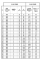
- FIG. 13 is a diagram showing the calculation conditions and calculation results of the finite element method used to derive condition A.
- FIG. 13 is a diagram showing the calculation conditions and calculation results of the finite element method used to derive condition A.
- FIG. 13 is a diagram for explaining the estimation accuracy using a regression equation obtained by multiple regression analysis.
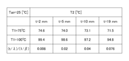
- 1 is a table comparing the temperatures of both surfaces of a substrate (glass plate) having a thermal conductivity ⁇ of 1 [W/(m ⁇ K)] and a thickness t of 2 mm or more and 19 mm or less.
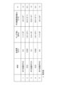
- 1 is a table illustrating examples of layer configurations and physical property values of a substrate.
- the X-axis, Y-axis, and Z-axis directions respectively represent directions parallel to the X-axis, Y-axis, and Z-axis.
- the X-axis, Y-axis, and Z-axis directions are mutually perpendicular.
- the XY plane, YZ plane, and ZX plane respectively represent imaginary planes parallel to the X-axis and Y-axis directions, imaginary planes parallel to the Y-axis and Z-axis directions, and imaginary planes parallel to the Z-axis and X-axis directions.
- the X-axis direction and the Z-axis direction are approximately parallel to a direction parallel to a horizontal plane (horizontal direction), and the Y-axis direction is approximately parallel to a vertical direction perpendicular to the horizontal plane.
- FIG. 1 is a cross-sectional view of an example of a substrate with a heating element according to an embodiment.
- the substrate with a heating element shown in FIG. 1 includes a substrate 50 and a heating element 40.
- the substrate 50 and the heating element 40 are stacked in the Z-axis direction.
- Substrate 50 has surface 51 facing the -Z axis direction and surface 52 facing the +Z axis direction.
- the thickness t of substrate 50 in the Z axis direction corresponds to the distance between surface 51 and surface 52.
- the substrate 50 has a fracture toughness value of 1 [MPa ⁇ m 1/2 ] or less.
- the fracture toughness value corresponds to the critical value of the stress intensity factor when fracture occurs.
- Examples of materials having a fracture toughness value of 1 [MPa ⁇ m 1/2 ] or less include silica glass, soda lime glass, borosilicate glass, alkali-free glass, and aluminosilicate glass.
- the substrate 50 is not limited to a single plate, and may be laminated glass, double glazing, Low-E glass, light control glass, or glass containing linear components.
- Low-E glass is also called low-emissivity glass, and may be glass in which a coating layer (transparent conductive film) with heat ray reflection function is coated on either surface of the window glass.
- Glass containing linear components may be meshed glass sheet in which a metal mesh is inserted inside the glass, or wired glass sheet in which metal wires that are not mesh-like are inserted inside the glass.
- the substrate 50 may be a substrate used for a display, a solar panel, an antenna, window glass, etc.
- the substrate 50 may be a glass plate for a building or a vehicle. Examples of glass plates for buildings include window glass, glass facades, and interior glass. Examples of glass plates for vehicles include window glass and interior glass. Applications of the substrate 50 with the heating element 40 are not limited to these.
- the heating element 40 generates heat by itself, for example, by passing a current through the heating element 40 to cause the heating element 40 to perform its function.
- the heating element 40 is provided on the substrate 50.
- the heating element 40 is provided on at least one of the surface and the interior of the substrate 50.
- FIG. 1 illustrates an example in which the heating element 40 includes a portion provided on the surface 51 of the substrate 50.
- the heating element 40 may also include a portion provided on the surface 52.
- the heating element 40 may be located between the multiple dielectric layers included in the substrate 50.
- the portion may be a conductor formed by printing or the like on the surface 51 or surface 52 of the substrate 50.
- conductors include conductors for antennas (radiating elements, filters, power supply elements, etc.), electrical wiring, heater wiring, etc.
- the heating element 40 may include a component that contacts the surface 51 or surface 52 of the substrate 50.
- Examples of such components include electronic components, electrical components, and mechanical components.
- Examples of electronic components include transistors and ICs (Integrated Circuits).
- Examples of ICs include analog ICs, driver ICs, power supply ICs, communication ICs, processors, memories, microcomputers, FPGAs (Field Programmable Gate Arrays), ASICs (Application Specific Integrated Circuits), and LSIs (Large Scale Integration).
- the heating element 40 may include a resistive element through which a current flows.
- the manner in which the heating element 40 comes into contact with the surface of the substrate 50 is not limited to a manner in which the heating element 40 comes into direct contact with the surface of the substrate 50, but may include a manner in which the heating element 40 comes into indirect contact with the surface via a thermally conductive member (e.g., solder, adhesive, etc.).
- a thermally conductive member e.g., solder, adhesive, etc.
- the heating element 40 may be attached to a circuit formed on the surface of the substrate 50 with solder or adhesive, or may be attached by fitting or fastening into a hole formed in the substrate 50.
- FIG. 2 is a plan view of an example of a substrate with a heating element according to one embodiment.
- the shapes of the substrate 50 and the heating element 40 are not particularly limited and may be rectangular or circular.
- FIG. 2 illustrates an example in which the shapes of the substrate 50 and the heating element 40 in plan view are each rectangular.
- the shape of the heating element 40 shown in FIG. 2 is a square with vertical and horizontal dimensions of a ⁇ a in plan view.
- the distance in plan view from the highest temperature point 41 generated by the heating element 40 to the edge 53 of the substrate 50 is b.
- the distance b corresponds to the shortest distance from the highest temperature point 41 to the closest edge among the edges that are the periphery of the substrate 50.
- the heating element 40 is provided on the substrate 50 as in FIG. 2, the larger the dimension a is or the shorter the distance b is, the greater the stress generated at the edge 53 closest to the highest temperature point 41, and the higher the possibility of thermal cracking of the substrate 50.
- the present disclosure provides a substrate with a heating element that can suppress thermal cracking of the substrate 50.
- the maximum stress generated in the substrate surface may occur in the surface (for example, near the heating element).
- the brittle material with a small fracture toughness value that is the subject of the present disclosure generally has a smaller fracture stress at the edge portion than in the surface, only the stress generated at the edge portion is focused on.
- the maximum stress at the edge occurs at the edge of the substrate 50 that is the shortest distance from the highest temperature point 41 when viewed in a plan view.
- the stress generated in the substrate 50 is ⁇ [MPa]
- the Young's modulus of the substrate 50 is E [MPa]
- the average linear expansion coefficient of the substrate 50 at 20 to 300°C is ⁇ [1/°C]
- the square root of the area where the heating element 40 overlaps with the substrate 50 in a planar view is a [mm]
- the distance in a planar view from the hottest point 41 of the heating element 40 to the edge 53 of the substrate 50 is b [mm]
- the difference between the temperature of the hottest point 41 and the ambient temperature is ⁇ T.
- the square root of the area where the heating element 40 overlaps with the substrate 50 in a planar view represents the average size of the heating element 40.
- the temperature of the hottest point 41 can be measured by thermography.
- the left side of formula 1 corresponds to the stress ⁇ [MPa] generated at the edge 53 of the substrate 50.
- the dimension a, distance b, and temperature difference ⁇ T are selected so that the value of the left side of formula 1 calculated from Young's modulus E, average linear expansion coefficient ⁇ , dimension a, distance b, and temperature difference ⁇ T is equal to or less than 6.9 [MPa], which is the edge fracture allowable stress of the substrate 50, thereby suppressing thermal cracking of the substrate 50.
- the value of 6.9 on the right side of formula 1 is approximately equal to the long-term edge fracture allowable stress [MPa] of soda-lime glass having a thickness t of 20 mm or less. If the substrate has a fracture toughness value of 1 [MPa ⁇ m 1/2 ] or less, it is considered that the edge fracture allowable stress of the substrate does not change significantly depending on the material of the substrate.
- Equation 1 is a regression equation similar to Hook's law.
- c1 corresponds to the Young's modulus of borosilicate glass and the Young's modulus normalized by the average linear expansion coefficient.
- (c2+c3 ⁇ a+c4 ⁇ b+c5 ⁇ T) corresponds to the strain of the substrate 50.
- c2, c3, c4, and c5 are regression coefficients.
- "0.208" in Equation 2 is the calculated value of "6.4 ⁇ 10 4 ⁇ 3.25 ⁇ 10 -6 ".
- 6.4 ⁇ 10 4 corresponds to the Young's modulus [MPa] of borosilicate glass.
- 3.25 ⁇ 10 -6 corresponds to the average linear expansion coefficient [1/°C] of borosilicate glass at 20 to 300°C.
- FIG. 3 and 4 are diagrams showing the calculation conditions and calculation results of the finite element method (FEM) used to derive condition A.
- FEM finite element method
- Figure 5 is a diagram to explain the estimation accuracy of the regression equation obtained by multiple regression analysis.
- the horizontal axis shows the maximum value of stress ⁇ calculated by FEM shown in Figures 3 and 4.
- the vertical axis shows the value of the left side of Equation 1 calculated by the regression equation (condition A) derived by multiple regression analysis using the least squares method from the FEM calculation conditions and calculation results shown in Figures 3 and 4, and represents stress ⁇ .
- the thickness of the substrate 50 is t [m]
- the thermal conductivity of the substrate 50 is ⁇ [W/(m ⁇ K)]
- the overall heat transfer coefficient of the substrate 50 is ⁇ [W/(m 2 ⁇ K)].
- the thickness t is set to (t/ ⁇ ) ⁇ (1/ ⁇ ) ⁇ 0.10...Formula 3a
- the thickness t is set to a length of 2 mm or more and 19 mm or less.
- the thermal resistance R2 [m 2 ⁇ K/W] of the surface 51 is expressed as (1/ ⁇ ).
- the thermal resistance R2 is 0.25 [m 2 ⁇ K/W].
- the thermal resistance R1 in the thickness direction of substrate 50 is sufficiently smaller than the thermal resistance R2 of surface 51 of substrate 50 (R1 ⁇ R2 x 0.1. In other words, formula 3a holds). Therefore, temperature T1 of surface 51 is approximately equal to temperature T2 of surface 52. Therefore, if thickness t is 2 mm or more and 19 mm or less, the temperature distribution in the thickness direction of substrate 50 is small, and the change in stress ⁇ due to differences in thickness t is small.
- Fig. 6 is a table comparing the temperature T1 of surface 51 and the temperature T2 of surface 52 for a substrate 50 (glass plate) with a thermal conductivity ⁇ of 1 [W/(m ⁇ K)] and a thickness t of 2 mm to 19 mm. As illustrated in Fig. 6, regardless of the thickness t, the temperature T1 of surface 51 is approximately equal to the temperature T2 of surface 52.
- the above formula 3a, 3b, or 3c is satisfied, or the thickness t is 2 mm or more and 19 mm or less.
- the thickness t is 2 mm or more, sufficient strength is obtained for attaching the three-dimensional heating element 40 to the surface 51. Furthermore, if the thickness t is 19 mm or less, when the heating element 40 includes an antenna, the radio wave transmission performance of the substrate 50 is good.
- the thickness t of the substrate 50 is more preferably 3 mm or more and 15 mm or less, and even more preferably 6 mm or more and 12 mm or less.
- the layer structure of the substrate 50 is not limited to a single layer, and may be multiple layers.
- the substrate 50 may include a dielectric layer such as a glass plate.
- the substrate 50 may include multiple layers with different Young's modulus E or average linear expansion coefficient ⁇ .
- c1 in the above conditional formula A1 be set to the largest value among the c1 of each of the multiple layers. This makes it possible to suppress thermal cracking of the layer that is most susceptible to cracking among the multiple layers.
- FIG. 7 is a table illustrating the layer structure of the substrate and the physical properties of each layer.
- Substrate 50 includes, from the first layer to the fifth layer, borosilicate glass, OCA (Optical Clear Adhesive), borosilicate glass, OCA, and borosilicate glass.
- c1 in the above conditional formula A1 is set to 1.2, which is the largest value of c1 for each of the multiple layers.
- FIG. 8 is a diagram for explaining the prediction accuracy by the regression equation obtained by multiple regression analysis.
- FIG. 8 shows the results of evaluating the stress ⁇ generated at the edge 53 by changing the temperature difference ⁇ T from 50° C. to 125° C. in a configuration in which two heating elements 40, each 20 mm long and 30 mm wide, are placed between the first and third layers of borosilicate glass of the substrate 50 including multiple layers shown in FIG. 7 and are bonded with OCA.
- the distance b for one heating element 40 is 60 mm, and the distance b for the other heating element 40 is 85 mm.
- the vertical axis shows the maximum value of the stress ⁇ calculated by FEM.
- the horizontal axis shows the value of the left side of Equation 1 calculated by the regression equation (Condition A) derived by multiple regression analysis using the least squares method from the FEM calculation conditions and calculation results shown in FIG. 3 and FIG. 4, and means the stress ⁇ .
- the distance b is 60 mm or 85 mm
- each stress ⁇ is plotted along a straight line with a slope of 1. Therefore, even if the substrate 50 includes multiple layers or the heating element 40 includes multiple heating elements, the estimation accuracy of the stress ⁇ obtained from the regression equation (condition A) can be said to be high.
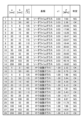
- FIG. 9 is a table showing an example of judgment based on condition A.
- condition A for multiple types of substrates 50 with heating elements 40 that differ in any of the dimension a, distance b, temperature difference ⁇ T, and coefficient c1, the cases where condition A is satisfied, in which the value of the left side of equation 1 calculated from conditional equation A1 is 6.9 or less, are shown as "OK,” and the cases where condition A is not satisfied are shown as "NG.”
- condition A is satisfied as a parameter of the substrate 50 with heating elements 40, thermal cracking of the substrate 50 can be suppressed.
- Heating element 41 Hottest point 50 Substrate 51, 52 Surface 53 Edge
Landscapes
- Chemical & Material Sciences (AREA)
- Engineering & Computer Science (AREA)
- Life Sciences & Earth Sciences (AREA)
- Chemical Kinetics & Catalysis (AREA)
- General Chemical & Material Sciences (AREA)
- Geochemistry & Mineralogy (AREA)
- Materials Engineering (AREA)
- Organic Chemistry (AREA)
- Civil Engineering (AREA)
- Structural Engineering (AREA)
- Resistance Heating (AREA)
Abstract
熱割れを抑制すること。 破壊靭性値が1[MPa・m1/2]以下の基板と、前記基板に設けられた発熱体と、を備え、前記基板のヤング率をE[MPa]、前記基板の20乃至300℃における平均線膨張係数をα[1/℃]、前記発熱体が前記基板に平面視で重複する面積の平方根をa[mm]、前記発熱体の最高温度点から前記基板のエッジまでの平面視での距離をb[mm]、前記最高温度点の温度と雰囲気温度との差をΔTとするとき、c1×(c2+c3×a+c4×b+c5×ΔT)≦6.9、c1=E×α/0.208という条件式が成立し、aが50mm未満のとき、c2=-2.279、c3=0.154、c4=-0.037、c5=0.069とし、aが50mm以上のとき、c2=0.116、c3=0.054、c4=-0.044、c5=0.101とする。
Description
本開示は、発熱体付き基板に関する。
従来、アンテナ導体が設けられたガラス板が知られている(例えば、下記の特許文献1参照)。
アンテナ導体等の発熱体が脆性の基板に設けられている場合、基板が発熱体の発熱により割れることがある。この割れの現象は、熱割れと呼ばれる。
本開示は、熱割れを抑制可能な、発熱体付き基板を提供する。
第1態様は、
破壊靭性値が1[MPa・m1/2]以下の基板と、
前記基板に設けられた発熱体と、を備え、
前記基板のヤング率をE[MPa]、前記基板の20乃至300℃における平均線膨張係数をα[1/℃]、前記発熱体が前記基板に平面視で重複する面積の平方根をa[mm]、前記発熱体の最高温度点から前記基板のエッジまでの平面視での距離をb[mm]、前記最高温度点の温度と雰囲気温度との差をΔTとするとき、
c1×(c2+c3×a+c4×b+c5×ΔT)≦6.9
c1=E×α/0.208
という条件式が成立し、
aが50mm未満のとき、
c2=-2.279、c3=0.154、c4=-0.037、c5=0.069
とし、
aが50mm以上のとき、
c2=0.116、c3=0.054、c4=-0.044、c5=0.101
とする、発熱体付き基板である。
破壊靭性値が1[MPa・m1/2]以下の基板と、
前記基板に設けられた発熱体と、を備え、
前記基板のヤング率をE[MPa]、前記基板の20乃至300℃における平均線膨張係数をα[1/℃]、前記発熱体が前記基板に平面視で重複する面積の平方根をa[mm]、前記発熱体の最高温度点から前記基板のエッジまでの平面視での距離をb[mm]、前記最高温度点の温度と雰囲気温度との差をΔTとするとき、
c1×(c2+c3×a+c4×b+c5×ΔT)≦6.9
c1=E×α/0.208
という条件式が成立し、
aが50mm未満のとき、
c2=-2.279、c3=0.154、c4=-0.037、c5=0.069
とし、
aが50mm以上のとき、
c2=0.116、c3=0.054、c4=-0.044、c5=0.101
とする、発熱体付き基板である。
第2態様は、第1態様の発熱体付き基板であって、
前記発熱体は、前記基板の表面に設けられた部分を含んでよい。
前記発熱体は、前記基板の表面に設けられた部分を含んでよい。
第3態様は、第1又は第2態様の発熱体付き基板であって、
前記発熱体は、前記基板の表面に形成された導体を含んでよい。
前記発熱体は、前記基板の表面に形成された導体を含んでよい。
第4態様は、第3態様の発熱体付き基板であって、
前記導体は、放射素子を含んでよい。
前記導体は、放射素子を含んでよい。
第5態様は、第3又は第4態様の発熱体付き基板であって、
前記導体は、フィルタを含んでよい。
前記導体は、フィルタを含んでよい。
第6態様は、第1から第5のいずれか一の態様の発熱体付き基板であって、
前記発熱体は、前記基板の表面に接触する部品を含んでよい。
前記発熱体は、前記基板の表面に接触する部品を含んでよい。
第7態様は、第1から第6のいずれか一の態様の発熱体付き基板であって、
前記基板の厚さをt[m]、前記基板の熱伝導率をλ[W/(m・K)]、前記基板の総合熱伝達係数をβ[W/(m2・K)]とするとき、
(t/λ)<(1/β)×0.10
が成立してもよい。
前記基板の厚さをt[m]、前記基板の熱伝導率をλ[W/(m・K)]、前記基板の総合熱伝達係数をβ[W/(m2・K)]とするとき、
(t/λ)<(1/β)×0.10
が成立してもよい。
第8態様は、第1から第7のいずれか一の態様の発熱体付き基板であって、
前記基板の厚さは、2mm以上19mm以下であってもよい。
前記基板の厚さは、2mm以上19mm以下であってもよい。
第9態様は、第1から第8のいずれか一の態様の発熱体付き基板であって、
前記基板は、ガラス板を含んでよい。
前記基板は、ガラス板を含んでよい。
第10態様は、第1から第9のいずれか一の態様の発熱体付き基板であって、
前記基板は、ヤング率又は平均線膨張係数が相違する複数の層を含んでもよく、
前記条件式におけるc1は、前記複数の層の各々のc1のうちで最も大きな値としてもよい。
前記基板は、ヤング率又は平均線膨張係数が相違する複数の層を含んでもよく、
前記条件式におけるc1は、前記複数の層の各々のc1のうちで最も大きな値としてもよい。
第11態様は、第1から第10のいずれか一の態様の発熱体付き基板であって、
前記基板は、建物用のガラス板でもよい。
前記基板は、建物用のガラス板でもよい。
第12態様は、第1から第10のいずれか一の態様の発熱体付き基板であって、
前記基板は、車両用のガラス板でもよい。
前記基板は、車両用のガラス板でもよい。
本開示によれば、熱割れを抑制可能な、発熱体付き基板を提供できる。
以下、実施形態について図面を参照して説明する。なお、理解の容易のため、図面における各部材の縮尺は実際とは異なる場合がある。平行、直角、直交、水平、垂直、上、下、左、右などの方向には、実施形態の作用及び効果を損なわない程度のずれが許容される。角部の形状は、直角に限られず、弓状に丸みを帯びてもよい。平行、直角、直交、水平、垂直には、略平行、略直角、略直交、略水平、略垂直が含まれてもよい。
本明細書では、三軸方向(X軸方向、Y軸方向、Z軸方向)の三次元直交座標系を用い、基板の幅方向又は横方向をX軸方向とし、基板の高さ方向又は縦方向をY軸方向とし、基板の厚さ方向をZ軸方向とする。基板の下から上に向かう方向を+Y軸方向とし、その反対方向を-Y軸方向とする。
X軸方向、Y軸方向、Z軸方向は、それぞれ、X軸に平行な方向、Y軸に平行な方向、Z軸に平行な方向を表す。X軸方向とY軸方向とZ軸方向は、互いに直交する。XY平面、YZ平面、ZX平面は、それぞれ、X軸方向及びY軸方向に平行な仮想平面、Y軸方向及びZ軸方向に平行な仮想平面、Z軸方向及びX軸方向に平行な仮想平面を表す。
例えば、X軸方向及びZ軸方向は、水平面に平行な方向(水平方向)に略平行であり、Y軸方向は、水平面に垂直な鉛直方向に略平行である。
図1は、一実施形態に係る発熱体付き基板の一例の断面図である。図1に示す発熱体付き基板は、基板50と発熱体40を備える。基板50と発熱体40は、Z軸方向に積層する。
基板50は、-Z軸方向に面する表面51と、+Z軸方向に面する表面52とを有する。基板50のZ軸方向の厚さtは、表面51と表面52との間の距離に相当する。
基板50は、破壊靭性値が1[MPa・m1/2]以下である。破壊靭性値は、破壊が起こる際の応力拡大係数の臨界値に相当する。破壊靭性値が1[MPa・m1/2]以下の材料の例として、シリカガラス、ソーダライムガラス、ホウ珪酸ガラス、無アルカリガラス、アルミノシリケートガラスなどが挙げられる。
基板50は、単板に限定されず、合わせガラスであってもよく、複層ガラスであってもよく、Low-Eガラスであってもよく、調光ガラスであってもよく、線状部材入りガラスであってもよい。Low-Eガラスは、低放射ガラスともいい、熱線反射機能を有するコーティング層(透明導電膜)が窓ガラスのいずれかの表面にコーティングされたものでもよい。線状部材入りガラスは、金属製の網がガラスの内部に挿入されている網入板ガラスであってもよく、金属製の網状ではない線がガラスの内部に挿入されている線入板ガラスであってもよい。
基板50は、ディスプレイ、ソーラーパネル、アンテナ、窓ガラスなどに使用される基板でもよい。基板50は、建物用又は車両用のガラス板でもよい。建物用のガラス板として、窓ガラス、ガラスファサード、室内用ガラスなどが挙げられる。車両用のガラス板として、窓ガラス、車内用ガラスなどが挙げられる。発熱体40付き基板50の用途は、これらに限られない。
発熱体40は、それ自体が熱を発生するものであり、例えば、発熱体40の機能を発揮させるために発熱体40に電流が流れることにより熱を発生させる。
発熱体40は、基板50に設けられている。発熱体40は、基板50の表面及び内部のうちの少なくとも一方に設けられている。図1は、発熱体40が基板50の表面51に設けられた部分を含む場合を例示する。発熱体40は、表面52に設けられた部分を含むものでもよい。基板50が複数の誘電体層を含む場合、発熱体40は、基板50に含まれる複数の誘電体層の間に位置してもよい。
発熱体40が基板50の表面に設けられた部分を含む場合、当該部分は、基板50の表面51又は表面52に印刷等により形成された導体でもよい。そのような導体の例として、アンテナ用導体(放射素子、フィルタ、給電素子など)、電気配線、ヒータ配線などが挙げられる。
発熱体40が基板50の表面に設けられた部分を含む場合、発熱体40は、基板50の表面51又は表面52に接触する部品を含んでもよい。そのような部品の例として、電子部品、電気部品、機械部品などが挙げられる。電子部品の例として、トランジスタ、IC(Integrated Circuit)などが挙げられる。ICの例として、アナログIC、ドライバーIC、電源IC、通信IC、プロセッサ、メモリ、マイクロコンピュータ、FPGA(Field Programmable Gate Array)、ASIC(Application Specific Integrated Circuit)、LSI(Large Scale Integration)などが挙げられる。発熱体40は、電流が流れる抵抗素子を含んでもよい。
発熱体40が基板50の表面に接触する形態には、発熱体40が基板50の表面に直接接触する形態に限られず、熱伝導性を有する部材(例えば、半田、接着剤など)を介して当該表面に間接的に接触する形態が含まれてもよい。例えば、発熱体40は、基板50の表面に形成された回路に半田又は接着剤等により取り付けられても、基板50に形成された穴に嵌め合い又は締結等により取り付けられてもよい。
図2は、一実施形態に係る発熱体付き基板の一例の平面図である。基板50及び発熱体40の形状は、四角形又は円形など、特に限定されない。図2は、基板50及び発熱体40の各々の平面視の形状が四角形の場合を例示する。
図2に示す発熱体40の形状は、平面視で縦横の寸法がa×aの正方形である。発熱体40の発熱による最高温度点41から基板50のエッジ53までの平面視での距離をbとする。距離bは、基板50の周縁であるエッジのうち最高温度点41から最も近接するエッジまでの最短距離に相当する。図2のように、発熱体40が基板50に設けられている形態では、寸法aが大きいほど、又は、距離bが短いほど、最高温度点41に最近接のエッジ53に発生する応力が大きくなり、基板50が熱割れする可能性が高くなる。このため、本開示は、基板50の熱割れを抑制可能な発熱体付き基板を提供する。条件によって、基板面内の最大発生応力は、面内(例えば発熱体近傍)で発生することがある。しかし、本開示で対象とする破壊靭性値の小さい脆性材料は、面内よりもエッジ部分での破壊応力が小さいことが一般的であるので、エッジ部の発生応力のみに着目する。また、エッジ部での最大発生応力は、最高温度点41から平面視での基板50の最短距離のエッジに発生する。
図2において、基板50に発生する応力をσ[MPa]、基板50のヤング率をE[MPa]、基板50の20乃至300℃における平均線膨張係数をα[1/℃]、発熱体40が基板50に平面視で重複する面積の平方根をa[mm]、発熱体40の最高温度点41から基板50のエッジ53までの平面視での距離をb[mm]、最高温度点41の温度と雰囲気温度との差をΔTとする。発熱体40が基板50に平面視で重複する面積の平方根(=寸法a)は、発熱体40の大きさの平均寸法を表す。最高温度点41の温度は、サーモグラフィにより測定可能である。
発熱体40付き基板50は、
c1×(c2+c3×a+c4×b+c5×ΔT)≦6.9 ・・・式1
c1=E×α/0.208 ・・・式2
という条件式A1が成立し、
aが50mm未満のとき、
c2=-2.279、c3=0.154、c4=-0.037、c5=0.069
とし、
aが50mm以上のとき、
c2=0.116、c3=0.054、c4=-0.044、c5=0.101
とする(条件A)。
c1×(c2+c3×a+c4×b+c5×ΔT)≦6.9 ・・・式1
c1=E×α/0.208 ・・・式2
という条件式A1が成立し、
aが50mm未満のとき、
c2=-2.279、c3=0.154、c4=-0.037、c5=0.069
とし、
aが50mm以上のとき、
c2=0.116、c3=0.054、c4=-0.044、c5=0.101
とする(条件A)。
発熱体40付き基板50が条件Aを満たすと、後述のシミュレーション及び判定例で示すように、基板50の熱割れが抑制される。
式1の左辺は、基板50のエッジ53に発生する応力σ[MPa]に相当する。ヤング率E、平均線膨張係数α、寸法a、距離b及び温度差ΔTから求められる式1の左辺の値が、基板50のエッジ破壊許容応力である6.9[MPa]以下になるように寸法a、距離b及び温度差ΔTが選定されることで、基板50の熱割れを抑制できる。式1の右辺の6.9は、厚さtが20mm以下のソーダライムガラスの長期のエッジ破壊許容応力[MPa]の値にほぼ等しい。破壊靭性値が1[MPa・m1/2]以下の基板であれば、基板のエッジ破壊許容応力は、基板の材質によっては大きく変わらないと考えられる。
式1は、フックの法則に似せた回帰式である。c1は、ホウ珪酸ガラスのヤング率及び平均線膨張係数で規格化したヤング率に相当する。(c2+c3×a+c4×b+c5×ΔT)は、基板50のひずみに相当する。c2,c3,c4,c5は、回帰係数である。式2内の「0.208」は、「6.4×104×3.25×10-6」を計算した値である。「6.4×10⁴」は、ホウ珪酸ガラスのヤング率[MPa]に相当する。「3.25×10⁻⁶」は、ホウ珪酸ガラスの20乃至300℃における平均線膨張係数[1/℃]に相当する。
次に、条件Aをシミュレーションにより導出する方法について説明する。
図3及び図4は、条件Aの導出に使用した有限要素法(FEM)の計算条件と計算結果を示す図である。基板50の表面51に発熱体40を設置した条件において、寸法a、距離b及び発熱体40の発熱量(温度)を変化させて、最高温度点41の温度及びエッジ53の応力σの分布(図2の右半分)を評価した。基板50は、発熱体40の寸法に応じて、一辺が400[mm]と1000[mm]の2種類の正方形のホウ珪酸ガラスを想定した。評価時のその他の条件は、
雰囲気温度Tair:25[℃]
基板50の厚さt:5[mm]
基板50の表面51の総合熱伝達係数:4[W/m2・K](静穏な室内を想定)
基板50のヤング率E:6.4×10⁴[MPa]
基板50の平均線膨張係数α:3.25×10⁻⁶[1/℃]
基板50の熱伝導率:1.2[W/m・K]
基板50のポアソン比:0.2
とした。
雰囲気温度Tair:25[℃]
基板50の厚さt:5[mm]
基板50の表面51の総合熱伝達係数:4[W/m2・K](静穏な室内を想定)
基板50のヤング率E:6.4×10⁴[MPa]
基板50の平均線膨張係数α:3.25×10⁻⁶[1/℃]
基板50の熱伝導率:1.2[W/m・K]
基板50のポアソン比:0.2
とした。
図5は、重回帰分析により得られた回帰式による推測精度を説明するための図である。横軸は、図3及び図4に示すFEMにより計算された応力σの最大値を示す。縦軸は、図3及び図4に示すFEMの計算条件及び計算結果から重回帰分析により最小二乗法を用いて導出された回帰式(条件A)により計算された式1の左辺の値であり、応力σを意味する。
aが2mm以上50mm未満のとき、「c2=-2.279、c3=0.154、c4=-0.037、c5=0.069」としたときの回帰式(条件A)の決定係数R2は、0.86である。aが50mm以上200mm以下のとき、「c2=0.116、c3=0.054、c4=-0.044、c5=0.101」としたときの回帰式(条件A)の決定係数R2は、0.89である。このように、決定係数R2は比較的高いので、回帰式(条件A)は、応力σの推定精度が高いと言える。
次に、基板50の厚さについて説明する。
基板50の厚さをt[m]、基板50の熱伝導率をλ[W/(m・K)]、基板50の総合熱伝達係数をβ[W/(m2・K)]とする。このとき、基板50の熱割れを抑制するためには、厚さtを、
(t/λ)<(1/β)×0.10 ・・・式3a
が成立する長さに設定することが好ましい。基板50の熱割れを抑制するためには、厚さtを、
(t/λ)<(1/β)×0.05 ・・・式3b
が成立する長さに設定することがより好ましく、
(t/λ)<(1/β)×0.02 ・・・式3c
が成立する長さに設定することがさらに好ましい。
(t/λ)<(1/β)×0.10 ・・・式3a
が成立する長さに設定することが好ましい。基板50の熱割れを抑制するためには、厚さtを、
(t/λ)<(1/β)×0.05 ・・・式3b
が成立する長さに設定することがより好ましく、
(t/λ)<(1/β)×0.02 ・・・式3c
が成立する長さに設定することがさらに好ましい。
あるいは、基板50の熱割れを抑制するためには、厚さtを2mm以上19mm以下の長さに設定することが好ましい。
例えば、図1において、発熱体40の熱が表面51から基板50を通って表面52に伝わるとする。基板50の厚さをt[m]、基板50の熱伝導率をλ[W/(m・K)]とすると、基板50の熱抵抗R1[m2・K/W]は、(t/λ)と表される。基板50がガラス板の場合、代表値としてλ=1とすると、厚さtが2mm以上19mm以下の場合、熱抵抗R1は、0.002[m2・K/W]以上0.019[m2・K/W]以下である。一方、表面51の総合熱伝達係数をβ[W/(m2・K)]とすると、表面51の熱抵抗R2[m2・K/W]は、(1/β)と表される。基板50がガラス板の場合、代表値としてβ=4(静穏空気の場合の代表値)とすると、熱抵抗R2は、0.25[m2・K/W]である。
このように、基板50として厚さtが2mm以上19mm以下のガラス板を想定した場合、基板50の厚さ方向の熱抵抗R1は、基板50の表面51の熱抵抗R2よりも十分に小さい(R1<R2×0.1。つまり、式3aが成立する)。よって、表面51の温度T1は、表面52の温度T2にほぼ等しい。したがって、厚さtが2mm以上19mm以下であれば、基板50の厚さ方向の温度分布は小さく、厚さtの違いによる応力σの変化は小さい。
図6は、熱伝導率λが1[W/(m・K)]で厚さtが2mm以上19mm以下の基板50(ガラス板)において、表面51の温度T1と表面52の温度T2を比較した表である。図6に例示するように、厚さtにかかわらず、表面51の温度T1は、表面52の温度T2にほぼ等しい。
したがって、基板50の熱割れを抑制するためには、上記の式3a,3bもしくは3cを満たす、又は、厚さtが2mm以上19mm以下であることが好ましい。
また、厚さtが2mm以上であれば、立体的な発熱体40を表面51に取り付けるための充分な強度が得られる。また、厚さtが19mm以下であれば、発熱体40がアンテナを含む場合、基板50の電波透過性能がよい。基板50の厚さtは、3mm以上15mm以下であることがより好ましく、6mm以上12mm以下であることがさらに好ましい。
次に、基板50の層構造について説明する。基板50の層構造は、単層に限らず、複数層でもよい。基板50は、ガラス板等の誘電体層を含んでもよい。
基板50は、ヤング率E又は平均線膨張係数αが相違する複数の層を含んでもよい。基板50の熱割れを抑制するためには、上記の条件式A1におけるc1は、複数の層の各々のc1のうちで最も大きな値とすることが好ましい。これにより、複数の層のうちで最も割れやすい層の熱割れを抑制できる。
図7は、基板の層構成と各物性値を例示する表である。基板50は、第1層から第5層まで順に、ホウ珪酸ガラス、OCA(Optical Clear Adhesive)、ホウ珪酸ガラス、OCA及びホウ珪酸ガラスを含む。この場合、上記の条件式A1におけるc1は、複数の層の各々のc1のうちで最も大きな1.2が採用される。
図8は、重回帰分析により得られた回帰式による推測精度を説明するための図である。図8は、図7に示す複数の層を含む基板50の第1層と第3層のホウ珪酸ガラスの間に縦20mm横30mmの二つの発熱体40があり、それらをOCAで接着した形態において、温度差ΔTを50℃から125℃まで変化させて、エッジ53に発生する応力σを評価した結果を示す。一方の発熱体40に関する距離bは、60mmであり、他方の発熱体40に関する距離bは85mmである。縦軸は、FEMにより計算された応力σの最大値を示す。横軸は、図3及び図4に示すFEMの計算条件及び計算結果から重回帰分析により最小二乗法を用いて導出された回帰式(条件A)により計算された式1の左辺の値であり、応力σを意味する。図8に示すように、距離bが60mmの場合も85mmの場合も、各々の応力σは傾き1の一直線上に沿ってプロットされている。よって、基板50が複数の層を含んでも、又は、発熱体40が複数の発熱体を含んでも、回帰式(条件A)から得られる応力σの推定精度は、高いと言える。
図9は、条件Aによる判定例を示す表である。図9は、寸法a、距離b、温度差ΔT及び係数c1のうちのいずれかが異なる複数種の発熱体40付き基板50について、条件式A1より算出された式1の左辺の値が6.9以下となる条件Aを満たす場合を「OK」と示し、条件Aを満たさない場合を「NG」と示している。発熱体40付き基板50のパラメータとして条件Aを満たす場合を選定することで、基板50の熱割れを抑制できる。
以上の通り、実施形態を説明したが、上記実施形態は、例として提示したものであり、上記実施形態により本発明が限定されるものではない。上記実施形態は、その他の様々な形態で実施されることが可能であり、発明の要旨を逸脱しない範囲で、種々の組み合わせ、省略、置き換え、変更などを行うことが可能である。これら実施形態やその変形は、発明の範囲や要旨に含まれると共に、特許請求の範囲に記載された発明とその均等の範囲に含まれる。
なお、2023年9月13日に出願された日本特許出願第2023-148377号の明細書、特許請求の範囲、図面及び要約書の全内容をここに引用し、本発明の明細書の開示として、取り入れるものである。
なお、2023年9月13日に出願された日本特許出願第2023-148377号の明細書、特許請求の範囲、図面及び要約書の全内容をここに引用し、本発明の明細書の開示として、取り入れるものである。
40 発熱体
41 最高温度点
50 基板
51,52 表面
53 エッジ
41 最高温度点
50 基板
51,52 表面
53 エッジ
Claims (12)
- 破壊靭性値が1[MPa・m1/2]以下の基板と、
前記基板に設けられた発熱体と、を備え、
前記基板のヤング率をE[MPa]、前記基板の20乃至300℃における平均線膨張係数をα[1/℃]、前記発熱体が前記基板に平面視で重複する面積の平方根をa[mm]、前記発熱体の最高温度点から前記基板のエッジまでの平面視での距離をb[mm]、前記最高温度点の温度と雰囲気温度との差をΔTとするとき、
c1×(c2+c3×a+c4×b+c5×ΔT)≦6.9
c1=E×α/0.208
という条件式が成立し、
aが50mm未満のとき、
c2=-2.279、c3=0.154、c4=-0.037、c5=0.069
とし、
aが50mm以上のとき、
c2=0.116、c3=0.054、c4=-0.044、c5=0.101
とする、発熱体付き基板。 - 前記発熱体は、前記基板の表面に設けられた部分を含む、請求項1に記載の発熱体付き基板。
- 前記発熱体は、前記基板の表面に形成された導体を含む、請求項2に記載の発熱体付き基板。
- 前記導体は、放射素子を含む、請求項3に記載の発熱体付き基板。
- 前記導体は、フィルタを含む、請求項3に記載の発熱体付き基板。
- 前記発熱体は、前記基板の表面に接触する部品を含む、請求項2に記載の発熱体付き基板。
- 前記基板の厚さをt[m]、前記基板の熱伝導率をλ[W/(m・K)]、前記基板の総合熱伝達係数をβ[W/(m2・K)]とするとき、
(t/λ)<(1/β)×0.10
が成立する、請求項1に記載の発熱体付き基板。 - 前記基板の厚さは、2mm以上19mm以下である、請求項1に記載の発熱体付き基板。
- 前記基板は、ガラス板を含む、請求項1に記載の発熱体付き基板。
- 前記基板は、ヤング率又は平均線膨張係数が相違する複数の層を含み、
前記条件式におけるc1は、前記複数の層の各々のc1のうちで最も大きな値とする、請求項1に記載の発熱体付き基板。 - 前記基板は、建物用のガラス板である、請求項1から10のいずれか一項に記載の発熱体付き基板。
- 前記基板は、車両用のガラス板である、請求項1から10のいずれか一項に記載の発熱体付き基板。
Applications Claiming Priority (2)
| Application Number | Priority Date | Filing Date | Title |
|---|---|---|---|
| JP2023148377 | 2023-09-13 | ||
| JP2023-148377 | 2023-09-13 |
Publications (1)
| Publication Number | Publication Date |
|---|---|
| WO2025057793A1 true WO2025057793A1 (ja) | 2025-03-20 |
Family
ID=95021247
Family Applications (1)
| Application Number | Title | Priority Date | Filing Date |
|---|---|---|---|
| PCT/JP2024/031354 Pending WO2025057793A1 (ja) | 2023-09-13 | 2024-08-30 | 発熱体付き基板 |
Country Status (1)
| Country | Link |
|---|---|
| WO (1) | WO2025057793A1 (ja) |
Citations (3)
| Publication number | Priority date | Publication date | Assignee | Title |
|---|---|---|---|---|
| JP2002216650A (ja) * | 2001-01-16 | 2002-08-02 | Matsushita Electric Ind Co Ltd | プラズマディスプレイ装置とその製造方法 |
| JP2011133721A (ja) * | 2009-12-25 | 2011-07-07 | Tokai Rubber Ind Ltd | 透明積層フィルム |
| JP2023006653A (ja) * | 2021-06-30 | 2023-01-18 | 日本板硝子株式会社 | 車両用ガラスモジュール |
-
2024
- 2024-08-30 WO PCT/JP2024/031354 patent/WO2025057793A1/ja active Pending
Patent Citations (3)
| Publication number | Priority date | Publication date | Assignee | Title |
|---|---|---|---|---|
| JP2002216650A (ja) * | 2001-01-16 | 2002-08-02 | Matsushita Electric Ind Co Ltd | プラズマディスプレイ装置とその製造方法 |
| JP2011133721A (ja) * | 2009-12-25 | 2011-07-07 | Tokai Rubber Ind Ltd | 透明積層フィルム |
| JP2023006653A (ja) * | 2021-06-30 | 2023-01-18 | 日本板硝子株式会社 | 車両用ガラスモジュール |
Similar Documents
| Publication | Publication Date | Title |
|---|---|---|
| JP2022169557A (ja) | ガラス用アンテナユニット、アンテナ付きガラス板、およびガラス用アンテナユニットの製造方法 | |
| EP2690656B1 (en) | Power device insulating heat radiation structure and circuit board | |
| TWI683748B (zh) | 積層玻璃製品與用於形成該製品之方法 | |
| JP6137267B2 (ja) | ヒートシンク付きパワーモジュール用基板及びパワーモジュール | |
| US12255402B2 (en) | Transparent antenna stack and assembly | |
| JP2018528461A (ja) | エレクトロクロミック素子組立体 | |
| CN101035407A (zh) | 具有金属芯的印刷电路板 | |
| KR101393072B1 (ko) | 전자파 간섭 저감 및 열 확산 강화 기능을 갖는 복합 시트 | |
| WO2019083606A1 (en) | FILMS OF SOFT COVERING LENSES | |
| US11267221B2 (en) | Laminated glass structures for electronic devices and electronic device covers | |
| KR100865771B1 (ko) | 방열용 코팅제 조성물 | |
| WO2007061033A1 (ja) | 照明装置とその製造方法 | |
| KR20260070127A (ko) | 발열체 구비 기판 | |
| TR201806673T4 (tr) | Yangın koruma levhası ve yangın koruma camı. | |
| JP2022519485A (ja) | アンテナユニットを備えるガラスユニット | |
| JP6569346B2 (ja) | 透明発熱板及び透明発熱板を備えた窓 | |
| KR101992749B1 (ko) | 멀티 히트 스프레더 | |
| KR102757085B1 (ko) | 도전체를 갖는 적층체 | |
| US20120181065A1 (en) | Multi-Layered Circuit Board Device | |
| JP7683608B2 (ja) | 周波数選択表面装荷部材 | |
| JP2016192386A (ja) | 透明発熱板、暖房器具及び住宅用窓 | |
| CN109534691B (zh) | 节能膜、夹层玻璃、中空玻璃及应用 | |
| JPH10270809A (ja) | 配線基板およびその製造方法 | |
| JP6801297B2 (ja) | 配線基板及び表示装置 | |
| JP6814414B2 (ja) | 透明発熱板及び透明発熱板を備えた窓 |
Legal Events
| Date | Code | Title | Description |
|---|---|---|---|
| 121 | Ep: the epo has been informed by wipo that ep was designated in this application |
Ref document number: 24865295 Country of ref document: EP Kind code of ref document: A1 |
|
| ENP | Entry into the national phase |
Ref document number: 2025545615 Country of ref document: JP Kind code of ref document: A |
|
| WWE | Wipo information: entry into national phase |
Ref document number: 2025545615 Country of ref document: JP |
|
| WWE | Wipo information: entry into national phase |
Ref document number: 2601001604 Country of ref document: TH |