WO2025053185A1 - フレームシステム及びシステム - Google Patents
フレームシステム及びシステム Download PDFInfo
- Publication number
- WO2025053185A1 WO2025053185A1 PCT/JP2024/031754 JP2024031754W WO2025053185A1 WO 2025053185 A1 WO2025053185 A1 WO 2025053185A1 JP 2024031754 W JP2024031754 W JP 2024031754W WO 2025053185 A1 WO2025053185 A1 WO 2025053185A1
- Authority
- WO
- WIPO (PCT)
- Prior art keywords
- frame
- unit
- belt
- fixed frame
- actuator
- Prior art date
- Legal status (The legal status is an assumption and is not a legal conclusion. Google has not performed a legal analysis and makes no representation as to the accuracy of the status listed.)
- Pending
Links
Images









Classifications
-
- A—HUMAN NECESSITIES
- A61—MEDICAL OR VETERINARY SCIENCE; HYGIENE
- A61H—PHYSICAL THERAPY APPARATUS, e.g. DEVICES FOR LOCATING OR STIMULATING REFLEX POINTS IN THE BODY; ARTIFICIAL RESPIRATION; MASSAGE; BATHING DEVICES FOR SPECIAL THERAPEUTIC OR HYGIENIC PURPOSES OR SPECIFIC PARTS OF THE BODY
- A61H1/00—Apparatus for passive exercising; Vibrating apparatus; Chiropractic devices, e.g. body impacting devices, external devices for briefly extending or aligning unbroken bones
- A61H1/02—Stretching or bending or torsioning apparatus for exercising
-
- B—PERFORMING OPERATIONS; TRANSPORTING
- B25—HAND TOOLS; PORTABLE POWER-DRIVEN TOOLS; MANIPULATORS
- B25J—MANIPULATORS; CHAMBERS PROVIDED WITH MANIPULATION DEVICES
- B25J19/00—Accessories fitted to manipulators, e.g. for monitoring, for viewing; Safety devices combined with or specially adapted for use in connection with manipulators
Definitions
- This disclosure relates to a frame system and a system.
- BWSTT Body Weight Supported Treadmill Training
- Non-Patent Document 1 proposes a wire system for supporting a user from four directions.
- the wire system proposed in Non-Patent Document 1 includes a pair of rails. Two carts are placed on each rail with a gap between them. Each cart moves along the rail. Four cables each connect the corresponding cart to a harness worn by the user. In this way, the user is supported by the four cables.
- Non-Patent Document 2 proposes a frame system (universal core frame) for movably supporting a load-relieving device.
- the frame system proposed in Non-Patent Document 2 comprises a pair of fixed frames and a movable frame.
- the movable frame is movably supported by the pair of fixed frames.
- a mobile unit is attached to the movable frame.
- the mobile unit is configured to be movable along the movable frame.
- the load-relieving device is attached to this mobile unit.
- the user can perform walking training even when not on a treadmill.
- the inventors of this case found that the conventional system had the following problems. That is, the wire system proposed in Non-Patent Document 1 requires a high ceiling because it uses a structure in which the system is suspended from four directions by wires. Therefore, it is difficult to use this wire system in small and medium-sized facilities with low ceilings.
- the frame system proposed in Non-Patent Document 2 can be used in facilities with low ceilings. Therefore, in order to introduce a load-relief system regardless of the size of the facility, it is preferable to adopt such a frame system. However, in this frame system, the wider the movement range of the mobile unit, the longer the length of the movable frame.
- the present disclosure has been made in consideration of these points, and its purpose is to provide a technique for increasing the mobility of a movable frame in a frame system.
- the present disclosure employs the following configurations. Note that the configurations of the following inventions can be combined as appropriate.
- a frame system comprises a first fixed frame, a second fixed frame, a movable frame and a moving unit.
- the first fixed frame extends in a first direction.
- the first fixed frame comprises a first output pulley, a first auxiliary pulley, an endless first belt and a first speed increasing unit.
- the first output pulley is arranged at one end of the first fixed frame.
- the first auxiliary pulley is arranged at the other end of the first fixed frame.
- the first belt is stretched between the first output pulley and the first auxiliary pulley.
- the first speed increasing unit is configured to receive an input of a driving force from a first actuator and output the input driving force to the first output pulley, thereby increasing the speed of movement of the first belt.
- the second fixed frame extends in the first direction and is arranged in parallel to the first fixed frame.
- the movable frame is supported by the first fixed frame and the second fixed frame and extends in a second direction intersecting the first direction.
- the movable frame is configured to move along the first fixed frame and the second fixed frame in response to the movement of the first belt by connecting one end of the movable frame to the first belt.
- the moving unit is supported by the movable frame and configured to move along the movable frame.
- a first speed-up unit is provided on the first fixed frame.
- the first speed-up unit outputs the driving force of the first actuator to the first output pulley, thereby speeding up the movement of the first belt.
- One end of the movable frame is connected to this first belt. Therefore, the speed-up by the first speed-up unit is transmitted to the movable frame via the first belt, which makes it easier for the movable frame to move in the first direction. Therefore, with this configuration, it is possible to increase the mobility of the movable frame in the frame system. Note that increasing the mobility of the movable frame is equivalent to increasing the mobility of the movable unit in the first direction. Any device may be attached to the movable unit.
- the second fixed frame may include a second output pulley, a second auxiliary pulley, an endless second belt, and a second speed increasing unit.
- the second output pulley may be disposed at one end of the second fixed frame.
- the second auxiliary pulley may be disposed at the other end of the second fixed frame.
- the second belt may be stretched between the second output pulley and the second auxiliary pulley.
- the second speed increasing unit may be configured to receive the input of the driving force from the second actuator and to increase the movement of the second belt by outputting the driving force input from the second actuator to the second output pulley.
- the other end of the movable frame may be connected to the second belt.
- the speed increasing force can be transmitted to both ends of the movable frame via the belt. This makes it possible to suppress the generation of a load in the rotational direction when transmitting the speed increasing force from each belt to each end of the movable frame, and as a result, the mobility of the movable frame can be increased. In other words, the movable frame can be moved smoothly.
- the movable frame may include a third output pulley, a third auxiliary pulley, an endless third belt, and a third speed-up unit.
- the third output pulley may be disposed at one of the one end and the other end of the movable frame.
- the third auxiliary pulley may be disposed at the other of the one end and the other end of the movable frame.
- the third belt may be stretched between the third output pulley and the third auxiliary pulley.
- the third speed-up unit may be configured to receive a driving force input by the third actuator and output the driving force input by the third actuator to the third output pulley, thereby speeding up the movement of the third belt.
- the moving unit may be connected to the third belt. According to this configuration, the mobility of the moving unit in the second direction can be increased by providing a speed-up unit on the movable frame as well.
- the moving unit may include a base portion having a cavity that opens in the vertical direction and configured to supply a plurality of linear structures including a first linear structure and a second linear structure from vertically above through the cavity to vertically below, and a rotation unit configured to rotate around the cavity in the vertical direction.
- the rotation unit may include a first moving portion that is arranged outside the cavity and configured to rotate around the vertical direction in response to the rotation of the rotation unit, and a second moving portion that is arranged outside the cavity and spaced apart from the first moving portion in the vertical direction and configured to rotate around the vertical direction in response to the rotation of the rotation unit while maintaining a positional relationship with the first moving portion.
- the first moving portion may include a first holding portion that is configured to hold a first end of a curl formed by the first linear structure hanging vertically downward from the cavity and then being taken around vertically upward, and the first linear structure may include a first holding portion that hangs further vertically downward from the first end.
- the second moving section is a second holding section configured to hold a second end of a curl formed when the second linear structure hangs vertically downward from the cavity and then is moved vertically upward, and the second linear structure may include a second holding section that hangs further vertically downward from the second end.
- any linear structure such as a power cable, a communication cable, a Bowden cable, or an air tube below the mobile unit.
- a cavity is provided in the base portion, multiple linear structures can be supplied in a state where they are gathered together below the mobile unit. This makes it easier to handle multiple linear structures.
- the linear structures will become entangled with each other, making it difficult to deploy each linear structure while maintaining a spaced state. In particular, when rotation is allowed, the linear structures will twist with each other, making it difficult to separate them.
- the first moving part and the second moving part are arranged in a circumferentially spaced relationship in the rotating unit.
- the first linear structure and the second linear structure are held by the first moving part and the second moving part, and are handled so as to hang down vertically downward. Since the first moving part and the second moving part are spaced apart, the first linear structure and the second linear structure can be maintained in a spaced relationship.
- each linear structure has slack for the curled portion, so the effect of the rotation on the portion hanging down from each moving part can be suppressed.
- the curled portion acts on the winding of the rotation, so that the portion of each linear structure beyond each moving part can rotate while maintaining a spaced state without being affected by the winding. Therefore, according to this configuration, multiple linear structures can be supplied below the moving unit in a spaced state, and even if they rotate around the vertical direction, the spaced state can be maintained.
- the linear structure may be any linear object that can be wired or piped.
- the linear structure may be, for example, a cable, a tube, etc. The type of cable and tube may be selected appropriately depending on the embodiment.
- the rotation unit may further include a central portion supported by the base portion so as to be rotatable around the vertical direction, a hollow portion that opens in the vertical up-down direction and communicates with the cavity of the base portion, a first arm portion extending vertically downward or at an angle from the central portion and connecting the central portion and the first moving portion, and a second arm portion extending vertically downward or at an angle from the central portion and connecting the central portion and the second moving portion.
- the moving portion is provided with a holding portion that holds the linear structure. Therefore, the load caused by the linear structure acts on the moving portion. In this configuration, the moving portion is disposed below the rotating portion (central portion). This allows the other portion to play the role of a stopper when it shifts to one side. In addition, the Yajirobe effect can increase the stability of the rotation.
- the moving unit may include a base portion having a cavity that opens in the vertical direction and is configured to pass the linear structure from above vertically downward through the cavity, and a rotation unit configured to rotate around the cavity in the vertical direction.
- the rotation unit may include a moving portion that is disposed outside the cavity and configured to rotate around the vertical direction in response to the rotation of the rotation unit.
- the moving portion may include a holding portion that is configured to hold the end of a curl that is formed when the linear structure hangs vertically downward from the cavity and then is taken up vertically upward, and the linear structure may include a holding portion that hangs further vertically downward from the end.
- the curled portion acts on the winding of the rotation, so that the portion of the linear structure beyond the moving portion can rotate without being affected by the winding. This allows even linear structures that are difficult to twist to rotate.
- the first actuator may be a variable stiffness actuator. This configuration enables impedance control in the first direction.
- variable stiffness actuator may be composed of a pair of artificial muscles. Artificial muscles can continuously output a relatively large force with low energy. Therefore, with this configuration, it is possible to reduce energy consumption when maintaining a state. Furthermore, the more the artificial muscles contract, the weaker their force becomes. Therefore, with this configuration, the output becomes smaller when the movable frame reaches the end, and the force hitting the end can be weakened.
- each artificial muscle may include a wire for inputting a driving force to the first acceleration unit, a stopper configured to transmit the driving force to the wire when each artificial muscle contracts in the direction of pulling the wire, and an elastic member configured to maintain the tension of the wire when each artificial muscle relaxes and the stopper is released.
- the stopper when the wire is stretched, the movement of the wire is stopped by the action of the stopper.
- the stopper when the wire is pulled back, the stopper is released, allowing the wire to move freely and the tension of the wire is maintained by the elastic member.
- each artificial muscle may be a fluid pressure artificial muscle. This configuration makes it easy to build the system.
- the second actuator When adopting a configuration in which the second speed-up unit is provided on the second fixed frame, the second actuator may be configured in the same manner as the first actuator. That is, in one example, the second actuator may be a variable stiffness actuator. In one example, the variable stiffness actuator of the second actuator may be composed of a pair of artificial muscles. In one example, each artificial muscle of the second actuator may be configured to include the above-mentioned wire, stopper, and elastic member. In one example, each artificial muscle of the second actuator may be a fluid pressure artificial muscle.
- the third actuator when a configuration is adopted in which a third speed-up unit is provided on the movable frame, the third actuator may be a variable stiffness actuator.
- This configuration enables impedance control in the second direction.
- the third actuator may also be configured in the same manner as the first actuator. That is, in one example, the variable stiffness actuator of the third actuator may be configured by a pair of artificial muscles.
- each artificial muscle of the third actuator may be configured to include the wire, stopper, and elastic member.
- each artificial muscle of the third actuator may be a fluid pressure artificial muscle.
- a load-relieving device may be attached to the moving unit.
- the mobility of the movable frame can be increased in situations where the load-relieving device is used.
- the moving unit may be equipped with a load-relieving device.
- the moving unit may include a base portion having a cavity that opens in the vertical direction and is configured to supply a plurality of linear structures including the first linear structure and the second linear structure of the load-relieving device from vertically above through the cavity to vertically below, and a rotating unit configured to rotate around the cavity in the vertical direction.
- the rotating unit may include a first moving portion that is arranged outside the cavity and configured to rotate around the vertical direction in response to rotation of the rotating unit, and a second moving portion that is arranged outside the cavity at a distance from the first moving portion in the vertical direction and configured to rotate around the vertical direction in response to rotation of the rotating unit while maintaining a positional relationship with the first moving portion.
- the first moving part is a first holding part configured to be formed by the first linear structure hanging vertically downward from the cavity and then being wound vertically upward, and the first linear structure may include a first holding part that hangs further vertically downward from a first end toward one of the left and right sides of the user of the load-relief device.
- the second moving part is a second holding part configured to hold a second end of a curl formed by the second linear structure hanging vertically downward from the cavity and then being wound vertically upward
- the second linear structure may include a second holding part that hangs further vertically downward from the second end toward the other of the left and right sides of the user.
- a robot arm may be attached to the moving unit.
- the mobility of the movable frame can be increased in situations where the robot arm is used.
- the moving unit may be attached with a robot arm.
- the movable frame may include a third output pulley, a third auxiliary pulley, an endless third belt, and a third speed increasing unit.
- the third output pulley may be disposed at one of the one end and the other end of the movable frame.
- the third auxiliary pulley may be disposed at the other of the one end and the other end of the movable frame.
- the third belt may be stretched between the third output pulley and the third auxiliary pulley.
- the third speed increasing unit may be configured to receive an input of a driving force from the third actuator and output the driving force input from the third actuator to the third output pulley, thereby increasing the speed of movement of the third belt.
- the moving unit may be connected to the third belt. This configuration can increase the mobility of the robot arm in the first direction and the second direction.
- the robot arm may be attached to the mobile unit via a balancer. From the standpoint of convenience, it is preferable to move the robot arm vertically upward when moving, and to lower it vertically downward when in use. With this configuration, the balancer makes this movement in the up and down directions easy, thereby enhancing convenience.
- a system may be configured using a plurality of frame systems each relating to any one of the above aspects.
- a system relating to one aspect of the present disclosure may include a first frame system arranged in a first space, and a second frame system arranged in a second space adjacent to the first space.
- Each frame system may include a first fixed frame, a second fixed frame, a movable frame, and a moving unit.
- the first fixed frame of each frame system may extend in a first direction.
- the first fixed frame of each frame system may include a first output pulley, a first auxiliary pulley, an endless first belt, and a first speed increasing unit.
- the first output pulley may be arranged at one end of the first fixed frame.
- the first auxiliary pulley may be arranged at the other end of the first fixed frame.
- the first belt may be stretched between the first output pulley and the first auxiliary pulley.
- the first speed increasing unit may be configured to accept an input of a driving force by the first actuator and output the input driving force to the first output pulley, thereby increasing the speed of movement of the first belt.
- the second fixed frame of each frame system may extend in a first direction and may be arranged in parallel to the first fixed frame.
- the movable frame of each frame system may be supported by the first fixed frame and the second fixed frame and may extend in a second direction intersecting the first direction.
- the movable frame of each frame system may be configured to move along the first fixed frame and the second fixed frame in response to the movement of the first belt by connecting one end of the movable frame to the first belt.
- the moving unit of each frame system may be supported by the movable frame and configured to move along the movable frame.
- the first frame system and the second frame system may be arranged at a distance such that a load-relieving device can be attached to the moving units of both the first frame system and the second frame system at the boundary between the first space and the second space and/or near the boundary. According to this configuration, the mobility of the movable frame in each frame system can be increased.
- the load-relieving device can be used continuously in the first space and the second space.
- the first space and the second space may be selected arbitrarily.
- one of the first space and the second space may be a bathroom.
- the load-relieving device can be used in the bathroom. This is expected to reduce the burden on the caregiver in the bathroom.
- the present disclosure provides a technique for increasing the mobility of a movable frame in a frame system.
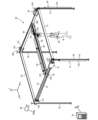
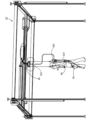
- FIG. 1 is a schematic diagram illustrating an example of a frame system according to an embodiment.
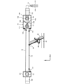
- FIG. 2A illustrates an example of a first fixed frame according to an embodiment.
- FIG. 2B is a schematic diagram illustrating an example of a state in which the first fixing frame (second fixing frame) according to the embodiment is viewed from the side.
- FIG. 2C is a diagram for explaining impedance control by the speed increasing unit of the fixed frame according to the embodiment.
- FIG. 3 is a schematic diagram showing an example of a movable frame according to an embodiment.
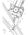
- FIG. 4A is a perspective view illustrating an example of a supporting portion of a movable frame and a first fixed frame according to an embodiment.
- FIG. 4B is a partial cross-sectional view that illustrates an example of a supporting portion of the movable frame and the first fixed frame in the embodiment.
- FIG. 4C is a partial cross-sectional view that illustrates an example of a supporting portion of the movable frame and the second fixed frame in the embodiment.
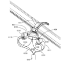
- FIG. 5A is a perspective view illustrating an example of a moving unit according to an embodiment.
- FIG. 5B is a partial cross-sectional view illustrating an example of the moving unit according to the embodiment.
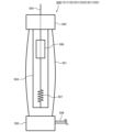
- FIG. 6 diagrammatically illustrates an example of the general configuration of an artificial muscle according to an embodiment.
- FIG. 7 is a diagram illustrating an example of a hardware configuration of a control device according to an embodiment.
- FIG. 8 illustrates an example of a software configuration of the control device according to the embodiment.
- FIG. 9 is a flowchart illustrating an example of a processing procedure of the control device according to the embodiment.
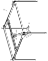
- FIG. 10 is a schematic diagram showing an example of a frame (a first fixed frame, a second fixed frame, and a movable frame) according to another embodiment.
- FIG. 11A is a schematic diagram showing an example of another situation in which the frame system of the present disclosure is used.
- FIG. 11B is a perspective view that illustrates an example of how a linear structure is handled by a mobile unit according to the present disclosure.
- FIG. 11C is a partial cross-sectional view showing a schematic example of how a linear structure is handled by a mobile unit according to the present disclosure.
- FIG. 12 is a schematic diagram showing an example of another situation in which the frame system of the present disclosure is used.
- FIG. 13 is a schematic diagram showing an example of another situation in which the frame system of the present disclosure is used.
- FIG. 14 is a flowchart illustrating another example of the processing procedure of the control device of the present disclosure.
- FIG. 15 illustrates a schematic diagram of an example of a system according to the present disclosure.
- FIG. 16A is a schematic diagram showing an example of a scene in which a user of a load-relieving device moves from a first space to a second space in the system of the present disclosure.
- FIG. 16B is a schematic diagram showing an example of a scene in which a user of the load-relieving device moves from the first space to the second space in the system of the present disclosure.
- FIG. 17 diagrammatically illustrates an example of the schematic configuration of an artificial muscle according to another embodiment.
- FIG. 18 illustrates a schematic diagram of an example of force control according to the present disclosure.
- FIG. 19A shows the results of the first experimental example.
- FIG. 19B shows the results of the first experimental example.
- FIG. 20A shows the results of the second experimental example.
- FIG. 20B shows the results of the second experimental example.
- the present embodiment an embodiment of one aspect of the present invention (hereinafter also referred to as "the present embodiment") will be described with reference to the drawings.
- the present embodiment described below is merely an example of the present invention in every respect. It goes without saying that various improvements and modifications can be made without departing from the scope of the present invention.
- a specific configuration according to the embodiment may be appropriately adopted.
- the attributes such as the shape, material, structure, etc. of each component described in this embodiment may be appropriately changed according to the embodiment.
- the data appearing in this embodiment is described in natural language, more specifically, it is specified in pseudo-language, commands, parameters, machine language, etc. that can be recognized by a computer.
- ⁇ 1 Configuration Example Fig. 1 shows a schematic diagram of an example of a frame system ST according to the present embodiment.
- the frame system ST according to the present embodiment includes a first fixed frame 10, a second fixed frame 20, a movable frame 30, and a moving unit 40.
- the first fixed frame 10 extends in the first direction (x direction) and is formed with a substantially rectangular cross section.
- the second fixed frame 20 also extends in the first direction (x direction) and is formed with a substantially rectangular cross section.
- the second fixed frame 20 is arranged in parallel to the first fixed frame 10.
- the length of each fixed frame (10, 20) may be determined appropriately depending on the embodiment. In the example of FIG. 1, the first fixed frame 10 and the second fixed frame 20 have substantially the same length. However, the length of each fixed frame (10, 20) is not limited to this example, and one of the first fixed frame 10 and the second fixed frame 20 may be longer than the other.
- the material of each fixed frame (10, 20) may be selected appropriately depending on the embodiment.
- the movable frame 30 extends in a second direction (y direction) intersecting the first direction and is formed with a substantially rectangular cross section.
- the movable frame 30 is supported by the first fixed frame 10 and the second fixed frame 20 so as to be movable along the first fixed frame 10 and the second fixed frame 20 (i.e., in the first direction).
- the length of the movable frame 30 may be determined appropriately depending on the embodiment.
- the moving unit 40 is supported by the movable frame 30.
- the moving unit 40 is configured to move along the movable frame 30.
- the materials of the movable frame 30 and the moving unit 40 may be selected appropriately depending on the embodiment.
- a load-relieving device 60 may be attached to the moving unit 40.
- FIG. 1 assumes an example of a situation in which the frame system ST of the present disclosure is used together with the load-relieving device 60.
- the first fixed frame 10 and the second fixed frame 20 may be fixed as appropriate.
- the frame system ST further includes four pillars (first pillar 55, second pillar 56, third pillar 57, and fourth pillar 58).
- Each of the pillars 55 to 58 is configured as a tension rod and is fixed by being clamped between the floor and the ceiling.
- Each end of the first fixed frame 10 is appropriately fixed near the ceiling of each of the first pillar 55 and the second pillar 56.
- each end of the second fixed frame 20 is appropriately fixed near the ceiling of each of the third pillar 57 and the fourth pillar 58.
- the first fixed frame 10 and the second fixed frame 20 are fixed at approximately the same height.
- the frame system ST further includes a third fixed frame 51 and a fourth fixed frame 52.
- the third fixed frame 51 and the fourth fixed frame 52 each extend in the second direction (y direction) and are formed to have a substantially rectangular cross section.
- the length of the third fixed frame 51 and the fourth fixed frame 52 is substantially the same as that of the movable frame 30.
- the third fixed frame 51 is stretched between the second support 56 and the third support 57 at substantially the same height as the first fixed frame 10 and the second fixed frame 20.
- Each end of the third fixed frame 51 is fixed to the second support 56 and the third support 57, respectively.
- the third fixed frame 51 connects one end of the first fixed frame 10 and the second fixed frame 20 to each other.
- the fourth fixed frame 52 is stretched between the first support 55 and the fourth support 58 at substantially the same height as the first fixed frame 10 and the second fixed frame 20.
- Each end of the fourth fixing frame 52 is fixed to the first support 55 and the fourth support 58, respectively.
- the fourth fixing frame 52 fixes the other ends of the first fixing frame 10 and the second fixing frame 20 to each other.
- the first direction is indicated as the "x direction”
- the second direction is indicated as the "y direction”
- the vertical direction is indicated as the "z direction”.
- the correspondence between the directions is merely an example and may be changed as appropriate depending on the embodiment.
- the relationship between the first and second directions may be reversed (for example, the first direction may be the y direction and the second direction may be the x direction). It is preferable that the first and second directions are horizontal, but as long as the movable frame 30 is movable, the first and second directions may be inclined with respect to the vertical direction.
- first fixed frame 10 and the second fixed frame 20 are arranged in parallel, so that the first fixed frame 10 and the second fixed frame 20 are parallel to each other.
- the arrangement in parallel is not limited to this example, and may include the first fixed frame 10 and the second fixed frame 20 being arranged at an angle.
- intersection of the first direction and the second direction is configured by the first direction and the second direction being perpendicular to each other (i.e., the angle at which the first direction and the second direction intersect is a right angle).
- the intersection of the first direction and the second direction is not limited to this example, and may include the first direction and the second direction intersecting at an acute angle or an obtuse angle.
- FIG. 2A shows an example of the first fixed frame 10 according to the present embodiment.
- Fig. 2B shows an example of the first fixed frame 10 (second fixed frame 20) according to the present embodiment as viewed from the side.
- the first fixed frame 10 includes a first output pulley 11, a first auxiliary pulley 12, an endless first belt 13, and a first speed increasing unit 14.
- the first output pulley 11 is disposed at one end 101 of the first fixed frame 10.
- the first auxiliary pulley 12 is disposed at the other end 102 of the first fixed frame 10.
- the diameters of the first output pulley 11 and the first auxiliary pulley 12 may be determined appropriately depending on the embodiment. In one example, the diameters of the first output pulley 11 and the first auxiliary pulley 12 may be the same. Also, in the example of FIG. 1, the first output pulley 11 may be housed in a housing 140 together with the first speed increasing unit 14, and the first auxiliary pulley 12 may be housed in a housing 121. Each housing (121, 140) may be omitted.
- the first belt 13 is stretched between the first output pulley 11 and the first auxiliary pulley 12.
- the first belt 13 is exposed between the housings (121, 140).
- a tensioner 131 that presses the first belt 13 from below is provided near the exit of the housing 121 of the first auxiliary pulley 12.
- a pair of tensioners (132, 133) are provided above and below near the exit of the housing 140 of the first output pulley 11. These tensioners 131 to 133 maintain the tension of the first belt 13 stretched between the first output pulley 11 and the first auxiliary pulley 12.
- the method of maintaining the tension of the first belt 13 is not limited to this example, and may be changed as appropriate depending on the embodiment.
- the state of the first belt 13 is not limited to this example, and may be selected as appropriate depending on the embodiment.
- the first belt 13 may be entirely housed or entirely exposed.
- the first belt 13 is disposed on the outside of the first fixed frame 10 (specifically, on the side opposite to the side on which the movable frame 30 is disposed). The location of the first belt 13 may be changed as appropriate depending on the embodiment.
- each end (101, 102) merely indicates the range over which the first belt 13 is wound, and the first fixed frame 10 may have a shape that extends further from each end (101, 102). That is, arranging the first output pulley 11 at one end 101 may mean arranging the first output pulley 11 at one end side relative to the first auxiliary pulley 12. Arranging the first auxiliary pulley 12 at the other end 102 may mean arranging the first auxiliary pulley 12 at the other end side relative to the first output pulley 11. The first output pulley 11 and the first auxiliary pulley 12 may be arranged near each end of the first fixed frame 10, or may be arranged away from each end. The relationship between the one end 101 and the other end 102 may be reversed.
- the axes of the first output pulley 11 and the first auxiliary pulley 12 face the second direction.
- the first output pulley 11 and the first auxiliary pulley 12 are arranged to rotate around the second direction to move the first belt 13 in the first direction.
- the first speed-up unit 14 is configured to receive a driving force input from the first actuator 15 and output the input driving force to the first output pulley 11, thereby accelerating the movement of the first belt 13.
- the first actuator 15 is configured with a pair of artificial muscles (151, 152).
- the first actuator 15 in this configuration is an example of a variable stiffness actuator.
- the type of each artificial muscle (151, 152) may be appropriately selected depending on the embodiment.
- each artificial muscle (151, 152) may be a fluid pressure artificial muscle.
- the fluid may be either a gas or a liquid.
- the fluid may be appropriately selected from, for example, air, oil, water, etc.
- each artificial muscle (151, 152) may be a pneumatic artificial muscle.
- each artificial muscle (151, 152) may be an artificial muscle other than a fluid pressure artificial muscle, such as a polymer actuator or a dielectric actuator.
- the arrangement of the artificial muscles (151, 152) may be determined as appropriate depending on the embodiment.
- the first speed increasing unit 14 is provided on the second support 56 side. Accordingly, the artificial muscles (151, 152) may be arranged on the second support 56.
- the first speed-up unit 14 includes a first input pulley 141 and an endless first speed-up belt 143.
- the first input pulley 141 includes a coaxial first drive gear 142. That is, the first input pulley 141 and the first drive gear 142 are configured as two-stage pulleys.
- the first input pulley 141 is arranged to face in the same direction as the first output pulley 11.
- the first output pulley 11 includes a coaxial first driven gear 111. That is, the first output pulley 11 and the first driven gear 111 are also configured as two-stage pulleys.
- the first driving gear 142 is disposed so as to face the first driven gear 111.
- the first speed-up belt 143 is stretched between the first driving gear 142 and the first driven gear 111.
- the positional relationship between the first driving gear 142 and the first driven gear 111 does not have to be limited to this example, and may be changed as appropriate depending on the embodiment.
- the positional relationship between the first input pulley 141 and the first output pulley 11 may be arbitrary.
- the first input pulley 141 may or may not face the first output pulley 11.
- a pair of tensioners (148, 149) are provided above and below between the first driving gear 142 and the first driven gear 111.
- the tension of the first speed-up belt 143 is maintained by these tensioners (148, 149).
- the method of maintaining the tension of the first speed-up belt 143 does not have to be limited to this example, and may be changed as appropriate depending on the embodiment.
- the diameter of the first drive gear 142 is larger than the diameter of the first driven gear 111.
- Other diameter relationships may be appropriately determined depending on the embodiment.
- the diameter of the first driven gear 111 may be smaller than the diameter of the first output pulley 11.
- the diameter of the first drive gear 142 may be larger than the diameter of the first input pulley 141.
- the wire of one artificial muscle is wound around the first input pulley 141 from one direction, and its end is fixed to the first input pulley 141. As a result, one artificial muscle is configured to rotate and drive the first input pulley 141 in one direction via the wire.
- the wire of the other artificial muscle is wound around the first input pulley 141 from the other direction, and its end is fixed to the first input pulley 141.
- the other artificial muscle is configured to rotate and drive the first input pulley 141 in the other direction via the wire.
- the input of driving force by the pair of artificial muscles (151, 152) is received by the first input pulley 141.
- the driving force input to the first input pulley 141 is output to the first output pulley 11 via the first speed-up belt 143.
- the rotation of the first input pulley 141 is accelerated according to the ratio between the first driving gear 142 and the first driven gear 111 and transmitted to the first output pulley 11.
- the first speed-up unit 14 accelerates the movement of the first belt 13.
- the movable frame 30 is configured to move along the first fixed frame 10 and the second fixed frame 20 in response to the movement of the first belt 13 by connecting one end 301 of the movable frame 30 to the first belt 13.
- the method of connecting the movable frame 30 and the first belt 13 is not particularly limited and may be selected appropriately depending on the embodiment.
- one end 301 of the movable frame 30 is connected to the first belt 13 via a coupling unit 36.
- the second fixed frame 20 is configured in the same manner as the first fixed frame 10. That is, the second fixed frame 20 includes a second output pulley 21, a second auxiliary pulley 22, an endless second belt 23, and a second speed increasing unit 24.
- the second output pulley 21 is disposed at one end 201 of the second fixed frame 20.
- the second auxiliary pulley 22 is disposed at the other end 202 of the second fixed frame 20.
- the diameters of the second output pulley 21 and the second auxiliary pulley 22 may be the same.
- the second output pulley 21 may be housed in a housing 240 together with the second speed increasing unit 24, and the second auxiliary pulley 22 may be housed in a housing 221.
- Each housing (221, 240) may be omitted.
- the second belt 23 is stretched between the second output pulley 21 and the second auxiliary pulley 22.
- the second belt 23 is exposed between the housings (221, 240).
- a tensioner 231 that presses the second belt 23 from below is provided near the exit of the housing 221 of the second auxiliary pulley 22.
- a pair of tensioners (232, 233) are provided above and below near the exit of the housing 240 of the second output pulley 21. These tensioners 231 to 233 maintain the tension of the second belt 23 stretched between the second output pulley 21 and the second auxiliary pulley 22.
- the method of maintaining the tension of the second belt 23 is not limited to this example and may be changed as appropriate depending on the embodiment.
- the state of the second belt 23 is not limited to this example and may be selected as appropriate depending on the embodiment.
- the second belt 23 may be entirely housed or entirely exposed.
- the second belt 23 is disposed on the outside of the second fixed frame 20 (specifically, on the side opposite to the side on which the movable frame 30 is disposed). The location of this second belt 23 may be changed as appropriate depending on the embodiment.
- each end (201, 202) merely indicates the range over which the second belt 23 is stretched, and the second fixed frame 20 may have a shape that extends further from each end (201, 202).
- the second output pulley 21 and the second auxiliary pulley 22 may be disposed near each end of the second fixed frame 20, or may be disposed away from each end.
- the relationship between the one end 201 and the other end 202 may be reversed.
- the axes of the second output pulley 21 and the second auxiliary pulley 22 face in the second direction.
- the second output pulley 21 and the second auxiliary pulley 22 are disposed so as to move the second belt 23 in the first direction by rotating around the second direction.
- one end 101 of the first fixed frame 10 faces one end 201 of the second fixed frame 20, and the other end 102 of the first fixed frame 10 faces the other end 202 of the second fixed frame 20.
- the positional relationship of the ends does not have to be limited to this example.
- one end 101 of the first fixed frame 10 faces the other end 202 of the second fixed frame 20, and the other end 102 of the first fixed frame 10 faces the one end 201 of the second fixed frame 20.
- the second speed-up unit 24 is configured to receive a driving force input from the second actuator 25 and output the input driving force to the second output pulley 21, thereby speeding up the movement of the second belt 23.
- the second actuator 25 is composed of a pair of artificial muscles (251, 252).
- This second actuator 25 is an example of a variable stiffness actuator.
- the type of each artificial muscle (251, 252) may be selected appropriately depending on the embodiment.
- each artificial muscle (251, 252) may be a fluid pressure artificial muscle.
- the fluid pressure artificial muscle may include a hybrid type artificial muscle configured to be able to output other driving forces such as electricity together with the fluid pressure.
- each artificial muscle (251, 252) may be an artificial muscle other than a fluid pressure artificial muscle.
- each artificial muscle (251, 252) may be determined appropriately depending on the embodiment.
- the second speed-up unit 24 is provided on the third support 57 side. Accordingly, each artificial muscle (251, 252) may be arranged on the third support 57.
- the second speed-up unit 24 includes a second input pulley 241 and an endless second speed-up belt 243.
- the second input pulley 241 includes a coaxial second drive gear 242.
- the second input pulley 241 is arranged to face the same direction as the second output pulley 21.
- the second output pulley 21 includes a coaxial second driven gear 211.
- the second drive gear 242 is arranged to face the second driven gear 211.
- the second speed-up belt 243 is stretched between the second drive gear 242 and the second driven gear 211. As long as the second speed-up belt 243 can be stretched, the positional relationship between the second drive gear 242 and the second driven gear 211 is not limited to this example and may be changed as appropriate depending on the embodiment.
- the positional relationship between the second input pulley 241 and the second output pulley 21 may be arbitrary.
- a pair of tensioners (248, 249) are provided above and below between the second drive gear 242 and the second driven gear 211. These tensioners (248, 249) maintain the tension of the second speed-up belt 243. Note that the method of maintaining the tension of the second speed-up belt 243 is not limited to this example, and may be changed as appropriate depending on the embodiment.
- the diameter of the second drive gear 242 is larger than the diameter of the second driven gear 211.
- Other diameter relationships may be appropriately determined depending on the embodiment.
- the diameter of the second driven gear 211 may be smaller than the diameter of the second output pulley 21.
- the diameter of the second drive gear 242 may be larger than the diameter of the second input pulley 241.
- the wire of one artificial muscle is wound around the second input pulley 241 from one direction, and its end is fixed to the second input pulley 241.
- the wire of the other artificial muscle is wound around the second input pulley 241 from the other direction, and its end is fixed to the second input pulley 241.
- the second speed-up unit 24 increases the speed of the movement of the second belt 23 in a manner similar to that of the first speed-up unit 14.
- the movable frame 30 is configured to move along the first fixed frame 10 and the second fixed frame 20 in response to the movement of the second belt 23 by connecting the other end 302 of the movable frame 30 to the second belt 23.
- the method of connecting the movable frame 30 and the second belt 23 is not particularly limited and may be selected appropriately depending on the embodiment.
- the other end 302 of the movable frame 30 is connected to the second belt 23 via a coupling unit 37.
- the pair of artificial muscles (151, 152) are driven in an antagonistic manner. That is, of the pair of artificial muscles (151, 152), one artificial muscle is connected to rotate and drive the first input pulley 141 in one direction, and the other artificial muscle is connected to rotate and drive the first input pulley 141 in the other direction.
- the position of the movable frame 30 is maintained at a balanced position of the pair of artificial muscles (151, 152).
- the movable frame 30 is shifted from this balanced position, one artificial muscle of the pair of artificial muscles (151, 152) is contracted, and the other artificial muscle is stretched.
- each of the pair of artificial muscles (151, 152) can be regarded as a pair of springs (SP1, SP2) connected to each other.
- the position of balance of the driving forces can be regarded as the balance point BP of the springs (SP1, SP2).
- the same is true for the pair of artificial muscles (251, 252) in the second fixed frame 20.
- each speed-up unit (14, 24) can shift the position of the balance point BP from the position of the movable frame 30 to move the movable frame 30 in that direction.
- the pair of artificial muscles (151, 152) of the first actuator 15 is an example of a variable stiffness actuator.
- the pair of artificial muscles (251, 252) of the second actuator 25 is also an example of a variable stiffness actuator.
- a variable stiffness actuator is an actuator whose stiffness can be changed.
- FIG. 2C is a diagram for explaining impedance control by each speed-up unit (14, 24) of each fixed frame (10, 20) according to this embodiment.
- the horizontal axis of the diagram indicates the contraction rate of one of the pair of artificial muscles (151, 152) (251, 252). Since there is a relationship in which when one artificial muscle expands, the other artificial muscle contracts (i.e., the pair of artificial muscles are driven in an antagonistic manner), the other artificial muscle is shown inverted.
- the resultant force F3 of the driving force F1 of one artificial muscle and the driving force F2 of the other artificial muscle is the driving force output from each actuator (15, 25).
- Point T0 where resultant force F3 becomes 0 corresponds to the above-mentioned equilibrium point BP.
- the slope of resultant force F3 corresponds to the stiffness of each actuator (15, 25).
- the rigidity of the artificial muscles can be changed as appropriate.
- the rigidity of each artificial muscle (151, 152) (251, 252) can be increased by increasing the fluid pressure in each artificial muscle (151, 152) (251, 252). This makes it possible to increase the slope of the resultant force F3 with respect to the contraction rate, as shown in FIG. 2C.
- each spring (SP1, SP2) stiffer it is possible to increase the restoring force that occurs when the movable frame 30 shifts from the equilibrium point BP.
- by decreasing the fluid pressure it is possible to decrease the rigidity of each artificial muscle (151, 152) (251, 252).
- [Movable frame] 3 is a schematic diagram showing an example of the movable frame 30 according to the present embodiment.
- the movable frame 30 has a similar configuration to the first fixed frame 10. That is, the movable frame 30 includes a third output pulley 31, a third auxiliary pulley 32, an endless third belt 33, and a third speed increasing unit 34.
- the third output pulley 31 is disposed at one of the one end 301 and the other end 302 of the movable frame 30.
- the third auxiliary pulley 32 is disposed at the other of the one end 301 and the other end 302 of the movable frame 30.
- the diameters of the third output pulley 31 and the third auxiliary pulley 32 may be the same.
- the third output pulley 31 may be housed in a housing 340 together with the third speed increasing unit 34, and the third auxiliary pulley 32 may be housed in a housing 321.
- Each housing (321, 340) may be omitted.
- the third belt 33 is stretched between the third output pulley 31 and the third auxiliary pulley 32.
- the third belt 33 is exposed between the housings (321, 340).
- a tensioner 331 that presses the third belt 33 from below is provided near the exit of the housing 321 of the third auxiliary pulley 32.
- a pair of tensioners (332, 333) are provided above and below near the exit of the housing 340 of the third output pulley 31.
- These tensioners 331 to 333 maintain the tension of the third belt 33 stretched between the third output pulley 31 and the third auxiliary pulley 32.
- the method of maintaining the tension of the third belt 33 is not limited to this example and may be changed as appropriate depending on the embodiment.
- the state of the third belt 33 is not limited to this example and may be selected as appropriate depending on the embodiment.
- the third belt 33 may be entirely housed or entirely exposed. In the example shown in Figure 3, the third belt 33 is partially omitted.
- the movable frame 30 may have a shape that extends further from each end (301, 302). One end 301 of the movable frame 30 is supported by the first fixed frame 10, and the other end 302 is supported by the second fixed frame 20.
- the parts supported by each fixed frame (10, 20) and the parts where each pulley (31, 32) is arranged may overlap or be separated.
- the third output pulley 31 and the third auxiliary pulley 32 may be arranged near each end of the movable frame 30, or may be arranged away from each end.
- the movable frame 30 may be supported by each fixed frame (10, 20) near each end or at a position away from each end.
- Each end (301, 302) may broadly refer to the support parts of each fixed frame (10, 20) and the arrangement parts of each pulley (31, 32).
- the axes of the third output pulley 31 and the third auxiliary pulley 32 face the first direction.
- the third output pulley 31 and the third auxiliary pulley 32 are arranged so that they rotate around the first direction to move the third belt 33 in the second direction.
- the third output pulley 31 is arranged at the other end 302 of the movable frame 30, and the third auxiliary pulley 32 is arranged at the one end 301.
- the arrangement of the third output pulley 31 and the third auxiliary pulley 32 is not limited to this example.
- the third output pulley 31 may be arranged at the one end 301, and the third auxiliary pulley 32 may be arranged at the other end 302. That is, the third output pulley 31 may be arranged at one of the one end 301 and the other end 302 of the movable frame 30, and the third auxiliary pulley 32 may be arranged at the other of the one end 301 and the other end 302 of the movable frame 30.
- the third speed-up unit 34 is configured to receive a driving force input from the third actuator 35 and output the input driving force to the third output pulley 31, thereby accelerating the movement of the third belt 33.
- the third actuator 35 is composed of a pair of artificial muscles (351, 352).
- This third actuator 35 is an example of a variable stiffness actuator.
- the type of each artificial muscle (351, 352) may be appropriately selected depending on the embodiment.
- each artificial muscle (351, 352) may be a fluid pressure artificial muscle.
- each artificial muscle (351, 352) may be an artificial muscle other than a fluid pressure artificial muscle.
- the arrangement of each artificial muscle (351, 352) may be appropriately determined depending on the embodiment.
- each artificial muscle (351, 352) is arranged on the upper part and one end 301 side of the movable frame 30.
- the wires of each artificial muscle (351, 352) extend from here and are input to the third speed increasing unit 34.
- the third speed-increasing unit 34 includes a third input pulley 341 and an endless third speed-increasing belt 343.
- the third input pulley 341 includes a coaxial third drive gear 342.
- the third input pulley 341 is arranged to face the same direction as the third output pulley 31.
- the third output pulley 31 includes a coaxial third driven gear 311.
- the third drive gear 342 is arranged to face the third driven gear 311.
- the third speed-increasing belt 343 is stretched between the third drive gear 342 and the third driven gear 311.
- the positional relationship between the third drive gear 342 and the third driven gear 311 is not limited to this example and may be changed as appropriate depending on the embodiment.
- the positional relationship between the third input pulley 341 and the third output pulley 31 may be arbitrary.
- a pair of tensioners (348, 349) are provided above and below between the third drive gear 342 and the third driven gear 311. These tensioners (348, 349) maintain the tension of the third speed-up belt 343.
- the method of maintaining the tension of the third speed-up belt 343 is not limited to this example, and may be changed as appropriate depending on the embodiment.
- the diameter of the third drive gear 342 is larger than the diameter of the third driven gear 311.
- Other diameter relationships may be appropriately determined depending on the embodiment.
- the diameter of the third driven gear 311 may be smaller than the diameter of the third output pulley 31.
- the diameter of the third drive gear 342 may be larger than the diameter of the third input pulley 341.
- the wire of one artificial muscle is wound around the third input pulley 341 from one direction, and its end is fixed to the third input pulley 341.
- the wire of the other artificial muscle is wound around the third input pulley 341 from the other direction, and its end is fixed to the third input pulley 341.
- the third speed-up unit 34 increases the speed of the movement of the third belt 33 in a manner similar to that of the first speed-up unit 14, etc.
- the moving unit 40 is supported by the movable frame 30 and connected to the third belt 33. As a result, the moving unit 40 is configured to move along the movable frame 30 in response to the movement of the third belt 33.
- the method of connecting the moving unit 40 and the third belt 33 is not particularly limited and may be appropriately selected depending on the embodiment. An example of a method of connecting the moving unit 40 will be described later.
- the pair of artificial muscles (351, 352) of the third actuator 35 is an example of a variable stiffness actuator.
- the pair of artificial muscles (351, 352) acts in the same manner as the pair of artificial muscles (151, 152). Therefore, in this embodiment, impedance control in the second direction is possible by the third speed increasing unit 34 of the movable frame 30, as in the first direction.
- the moving unit 40 can be rigidly supported in the second direction, and the restoring force generated when the moving unit 40 is displaced from the equilibrium point in the second direction can be increased.
- the moving unit 40 can be flexibly supported in the second direction, and the restoring force generated when the moving unit 40 is displaced from the equilibrium point in the second direction can be reduced.
- the stiffness in the first direction and the second direction may be appropriately controlled.
- an endless belt is used for each belt (13, 23, 33) and each speed-increasing belt (143, 243, 343).
- the endless belt may be produced by any method.
- the belt may be formed to be endless from the beginning.
- the endless belt may be formed by connecting the ends of a single belt.
- the belt may include a chain and a wire in addition to a general belt.
- FIG. 4A is a perspective view showing an example of a support portion of the movable frame 30 and the first fixed frame 10 according to the present embodiment.
- Fig. 4B is a partial cross-sectional view showing an example of a support portion of the movable frame 30 and the first fixed frame 10 (second fixed frame 20) according to the present embodiment. Note that in Fig. 4B, the upper circumference of the first belt 13 is omitted.
- the connecting unit 36 includes a pair of first members 360, a second member 361, a slide unit 362, a third member 363, a fourth member 364, and a fifth member 365.
- Each first member 360 is formed in a flat plate shape.
- the pair of first members 360 are fixed on the lower side of the movable frame 30 in a state in which the one end 301 of the movable frame 30 is sandwiched between them.
- Each first member 360 extends slightly downward from the movable frame 30 and is fixed to one end of the second member 361. As a result, the pair of first members 360 connects the one end 301 of the movable frame 30 to the second member 361.
- the first belt 13 is disposed on the outside of the first fixed frame 10 (i.e., the opposite side to the movable frame 30).
- the second member 361 is formed in a flat plate shape and extends from one end 301 of the movable frame 30, passing under the first fixed frame 10, toward the outside of the first fixed frame 10.
- the other end of the second member 361 is connected to the fourth member 364 via a flat plate-shaped third member 363.
- One end of the third member 363 is fixed to the other end of the second member 361, and the other end of the third member 363 is fixed to one end of the fourth member 364.
- the fourth member 364 is formed in a flat plate shape and extends from the other end of the third member 363, passing under the first belt 13 (lower circumference), to a position slightly outside the first belt 13. The other end of the fourth member 364 is fixed to the flat plate-shaped fifth member 365 with the first belt 13 sandwiched between them. This connects one end 301 of the movable frame 30 to the first belt 13.
- the first fixed frame 10 has an internal space 190 with a generally rectangular cross section at the lower side, and this internal space 190 communicates with the outer space via a groove 193 provided at the lower end of the first fixed frame 10.
- Each edge (191, 192) located in the width direction (second direction) of the groove 193 is bent inward, so that the width of the groove 193 is narrower than the width of the internal space 190.
- the internal space 190 and each edge (191, 192) form a linear guide.
- the slide unit 362 enters the internal space 190 from the lower side of the first fixed frame 10 through the groove 193 and is supported by the first fixed frame 10 by being hooked on each edge (191, 192), and is configured to slide using each edge (191, 192) as a track.
- the slide unit 362 includes a base 3620, a pair of vertical wheels (3621, 3622), and a pair of horizontal wheels (3623, 3624).
- the lower end of the base 3620 is fixed to the second member 361.
- the length of the base 3620 in the width direction (left-right direction in FIG. 4B) is shorter than the groove 193, so that the base 3620 extends upward from the second member 361 and enters the internal space 190.
- a pair of vertical wheels (3621, 3622) are rotatably connected to the base 3620 via an axle in the width direction.
- the distance between the pair of vertical wheels (3621, 3622) (the length in the left-right direction in FIG. 4B) is approximately the same as or wider than the length in the width direction of the groove 193, so that the slide unit 362 hooks onto each edge (191, 192).
- the thickness of each vertical wheel (3621, 3622) is approximately the same as or narrower than the width of the folded portion (track) of each edge (191, 192).
- Each vertical wheel (3621, 3622) rotates and moves using the upper end of each edge (191, 192) as a track, so that the movable frame 30 can slide along the first fixed frame 10 via the slide unit 362.
- a pair of horizontal wheels (3623, 3624) are rotatably connected to the base 3620 in the width direction so as not to interfere with the vertical wheels (3621, 3622).
- the horizontal wheel 3623 is disposed near the inner wall surface on the edge 191 side of the first fixed frame 10.
- the horizontal wheel 3624 is disposed near the inner wall surface on the edge 192 side of the first fixed frame 10.
- the pair of horizontal wheels (3623, 3624) abut against the inner wall surfaces in the respective directions, and can receive axial loads against the axes of the pair of vertical wheels (3621, 3622) that act as guides. This allows the movable frame 30 to slide smoothly.
- the configuration of the slide unit 362 may be changed as appropriate depending on the embodiment.
- the number and arrangement of the vertical wheels (3621, 3622) and horizontal wheels (3623, 3624) are not limited to the example of FIG. 4B, and may be changed as appropriate depending on the embodiment.
- one or more vertical wheels may be attached to the base 3620 to fill the gap. This allows the pair of vertical wheels (3621, 3622) to bear radial load against their axes, thereby making it possible to further smooth the sliding of the movable frame 30.
- the slide unit 362 supports one end 301 of the movable frame 30 on the first fixed frame 10 at approximately the same height as the first fixed frame 10.
- FIG. 4C is a partial cross-sectional view showing an example of the support portion of the movable frame 30 and the second fixed frame 20 according to this embodiment. Note that in FIG. 4C, the upper circumference of the second belt 23 is omitted. In this embodiment, the other end 302 of the movable frame 30 is supported by the second fixed frame 20 and connected to the second belt 23 via a connecting unit 37.
- the configuration of the connecting unit 37 may be appropriately determined according to the embodiment.
- the connecting unit 37 may have a configuration similar to that of the connecting unit 36. That is, the connecting unit 37 includes a pair of first members 370, a second member 371, a slide unit 372, a third member 373, a fourth member 374, and a fifth member 375.
- the pair of first members 370 connect the other end 302 of the movable frame 30 to the second member 371.
- the second belt 23 is disposed on the outside of the second fixed frame 20 (i.e., the opposite side to the movable frame 30). Accordingly, the second member 371 extends from the other end 302 of the movable frame 30, passing under the second fixed frame 20, toward the outside of the second fixed frame 20. The other end of the second member 371 is connected to the fourth member 374 via the third member 373. The fourth member 374 extends from the other end of the third member 373, passing under the second belt 23 (lower circumference), to a position slightly outside the second belt 23. The fourth member 374 is fixed to the fifth member 375 with the second belt 23 sandwiched between them. As a result, the other end 302 of the movable frame 30 is connected to the second belt 23.
- the second fixed frame 20 has an internal space 290 with a generally rectangular cross section at the lower side, and this internal space 290 communicates with the outer space via a groove 293 provided at the lower end of the second fixed frame 20.
- Each edge portion (291, 292) located in the width direction of the groove 293 is bent inward, so that the width of the groove 293 is narrower than the width of the internal space 290.
- the slide unit 372 enters the internal space 290 from the lower side of the second fixed frame 20 through the groove 293 and is supported by the second fixed frame 20 by being hooked on each edge portion (291, 292), and is configured to slide using each edge portion (291, 292) as a track.
- the slide unit 372 includes a base 3720, a pair of vertical wheels (3721, 3722), and a pair of horizontal wheels (3723, 3724).
- the lower end of the base 3720 is fixed to the second member 371.
- the length of the base 3720 in the width direction is shorter than the groove 293, so that the base 3720 extends upward from the second member 371 and enters the internal space 290.
- a pair of vertical wheels (3721, 3722) are rotatably connected to the base 3720 in the width direction via an axle.
- the pair of vertical wheels (3721, 3722) are configured in the same manner as the pair of vertical wheels (3621, 3622).
- the slide unit 372 hooks onto each edge (291, 292) via the pair of vertical wheels (3721, 3722).
- Each vertical wheel (3721, 3722) rotates and moves using the upper end of each edge (291, 292) as a track, allowing the movable frame 30 to slide along the second fixed frame 20 via the slide unit 372.
- a pair of horizontal wheels (3723, 3724) are rotatably connected to the base 3720 in the width direction so as not to interfere with the vertical wheels (3721, 3722).
- the horizontal wheel 3723 is disposed near the inner wall surface on the edge 291 side of the second fixed frame 20.
- the horizontal wheel 3724 is disposed near the inner wall surface on the edge 292 side of the second fixed frame 20.
- the pair of horizontal wheels (3723, 3724) abut against the inner wall surfaces in the respective directions, and can receive axial loads against the axes of the pair of vertical wheels (3721, 3722) that act as guides. This allows the movable frame 30 to slide smoothly.
- the configuration of the slide unit 372 may be changed as appropriate depending on the embodiment.
- the number and arrangement of the vertical wheels (3721, 3722) and the horizontal wheels (3723, 3724) are not limited to the example of FIG. 4C, and may be changed as appropriate depending on the embodiment.
- one or more vertical wheels may be attached to the base 3720 to fill the gap. This allows the pair of vertical wheels (3721, 3722) to bear radial load against the axis, and as a result, the sliding of the movable frame 30 can be made even smoother.
- each component of the coupling unit 37 may be configured in the same way as each component of the coupling unit 36.
- the other end 302 of the movable frame 30 is supported by the second fixed frame 20 at approximately the same height as the second fixed frame 20 by such a slide unit 372.
- [Mobile unit] 5A and 5B are a perspective view and a partial cross-sectional view showing an example of the moving unit 40 according to the present embodiment.
- the moving unit 40 includes a pair of base portions (41, 42), a rotating unit 43, a sliding unit 45, and a connecting portion 46.
- the pair of base parts (41, 42) are an example of a base part of the present disclosure.
- the pair of base parts (41, 42) have cavities (410, 420) that open in the vertical direction.
- the rotation unit 43 is configured to rotate around the cavity (410, 420) in the vertical direction. Rotation around the vertical direction corresponds to rotation around the vertical direction as the rotation axis. Note that the rotation axis may be tilted from the vertical direction depending on the shaking of the moving unit 40, etc. Rotation around the vertical direction may include rotation around such a rotation axis tilted from the vertical direction.
- the rotation unit 43 includes a first moving part 434 and a second moving part 435.
- the first moving part 434 is arranged outside the cavity (410, 420) and is configured to rotate around the vertical direction in response to the rotation of the rotation unit 43.
- the first moving part 434 includes a first holding part 436.
- the second moving part 435 is disposed outside the cavity (410, 420) and spaced apart from the first moving part 434 in the vertical direction, and is configured to rotate and move in the vertical direction in response to the rotation of the rotation unit 43 while maintaining a positional relationship with the first moving part 434.
- the second moving part 435 includes a second holding part 437.
- Such a rotation unit 43 may be configured appropriately depending on the embodiment.
- the rotating unit 43 further includes a central portion 431, a first arm portion 432, and a second arm portion 433.
- each portion 431 to 435 of the rotating unit 43 is formed in a flat plate shape and has a bent shape at each arm portion (432, 433).
- the central portion 431 is supported by a pair of base portions (41, 42) so as to be rotatable around the vertical direction.
- the upper base portion 41 is formed in a cylindrical shape.
- the lower base portion 42 has a circular shape with a larger diameter than the upper base portion 41, and has a shape in which the diameter decreases once after moving downward while keeping the diameter constant, and then the diameter increases.
- the central portion 431 is supported by the pair of base portions (41, 42) by being rotatably sandwiched between the upper base portion 41 and the lower base portion 42.
- the central portion 431 also has a hollow portion 430 that opens in the vertical up-down direction.
- the hollow portion 430 communicates with the cavities (410, 420) of the pair of base portions (41, 42).
- a thrust bearing may be disposed between the central portion 431 and the lower base portion 42.
- the thrust bearing can receive the axial load on the rotation shaft of the rotating unit 43. This allows the rotating unit 43 to rotate smoothly.
- a hollow shaft may be provided in the central portion 431, and a radial bearing may be disposed on the hollow shaft. The radial bearing also allows the rotating unit 43 to rotate smoothly.
- the first arm 432 has a shape that extends from the central portion 431 at an incline vertically downward.
- the first arm 432 is configured to connect the central portion 431 and the first moving portion 434.
- the direction in which the first arm 432 extends does not need to be limited to this example.
- the first arm 432 may have a shape that extends vertically downward from the central portion 431.
- the second arm 433 has a shape that extends from the central portion 431 at an incline vertically downward.
- the second arm 433 is configured to connect the central portion 431 and the second moving portion 435. The direction in which the second arm 433 extends does not need to be limited to this example.
- the second arm 433 may have a shape that extends vertically downward from the central portion 431.
- the extending shape of each arm (432, 433) may include a shape that is at least partially curved.
- the first moving part 434 and the second moving part 435 are connected via the central part 431 and each arm (432, 433) and are configured to rotate and move in response to the rotation of the central part 431.
- the first moving part 434 and the second moving part 435 can rotate and move while maintaining a state of being separated around the vertical direction.
- the positional relationship between the first moving part 434 and the second moving part 435 is not particularly limited and may be appropriately determined depending on the embodiment.
- the first moving part 434 and the second moving part 435 may be arranged so as to be separated at a positional relationship of 180 degrees in the circumferential direction.
- the movable frame 30 has a U-shaped groove 385 on the upper side.
- the upper end of the groove 385 is open (open).
- An L-shaped bracket 38 is attached to the side wall on the upper side of the movable frame 30 on the side opposite the third belt 33.
- One or more linear structures of a device to be attached to the mobile unit 40 can be placed in this groove 385 and bracket 38.
- the type of linear structure is not particularly limited and may be selected appropriately depending on the embodiment.
- the linear structure may include a cable, a tube, a harness, other objects that are wired or piped, a combination of these, etc.
- the cable may be, for example, a Bowden cable, a power cable, a signal line, a communication cable, etc.
- the tube may be, for example, an air tube, etc.
- the upper base portion 41 is provided with a pair of guide portions (441, 442).
- the guide portion 441 extends from the side wall of the upper base portion 41 on the groove 385 side toward the movable frame 30 and is configured to draw a linear structure placed in the groove 385 toward the upper base portion 41.
- the guide portion 442 extends from the side wall of the upper base portion 41 on the bracket 38 side toward the movable frame 30 and is configured to draw a linear structure placed on the bracket 38 toward the upper base portion 41.
- the pair of base portions (41, 42) are configured to pass one or more linear structures drawn in by the pair of guide portions (441, 442) vertically from above through the cavities (410, 420) and supply them vertically downward.
- one or more linear structures are supplied from above to below the moving unit 40 by passing through the cavity 410 of the upper base portion 41, the hollow portion 430 of the central portion 431, and the cavity 420 of the lower base portion 42 in that order.
- the pair of guide portions (441, 442) may be omitted.
- the one or more linear structures may be directly drawn into the pair of base portions (41, 42).
- a plurality of linear structures may be supplied vertically below the moving unit 40 by a pair of base portions (41, 42).
- the plurality of linear structures may include a first linear structure and a second linear structure.
- the first holding portion 436 of the first moving portion 434 may be configured to hold a first end of a curl formed by the first linear structure hanging vertically downward from the cavity (410, 420) and then being wrapped around vertically upward.
- the first linear structure may hang further vertically downward from the first end.
- the second holding portion 437 of the second moving portion 435 may be configured to hold a second end of a curl formed by the second linear structure hanging vertically downward from the cavity (410, 420) and then being wrapped around vertically upward.
- the second linear structure may hang further vertically downward from the second end.
- the configuration of the holding parts (436, 437) is not particularly limited and may be appropriately selected depending on the embodiment.
- Each of the holding parts (436, 437) may be composed of, for example, a bolt that holds a wire.
- a pair of base portions (41, 42) are provided with cavities (410, 420), so that a plurality of linear structures can be supplied in a concentrated state below the moving unit 40. This makes it easier to handle a plurality of linear structures.
- the first moving portion 434 and the second moving portion 435 are arranged spaced apart in the circumferential direction. After forming the curl, the first linear structure and the second linear structure are held by the first moving portion 434 and the second moving portion 435, and are handled so as to hang down vertically downward. Since the first moving portion 434 and the second moving portion 435 are spaced apart, the first linear structure and the second linear structure can be maintained in a spaced apart state.
- each linear structure has a slack portion for the curled portion (i.e., the curled portion is unwound by the rotation), so the portions hanging down from each moving section (434, 435) can rotate while maintaining a distance from each other. Therefore, according to this embodiment, multiple linear structures are supplied below the moving unit 40 while being spaced apart, and can maintain that spaced state even when rotating vertically.
- each moving part (434, 435) is positioned below the rotating part (central part 431) of the rotating unit 43. This allows one of the pair of moving parts (434, 435) to act as a stopper when the other shifts out of place. For example, if the rotating unit 43 shifts towards the first moving part 434, the inner walls of the second arm part 433 and the second moving part 435 hit the lower base part 42, stopping the shifting of the rotating unit 43. In addition, the Yajirobe effect can increase the stability of the rotation of the rotating unit 43.
- a load-relief device 60 may be attached to the mobile unit 40.
- the load-relief device 60 includes a pair of artificial muscles (601, 602), a pair of wires (603, 604), and a pair of attachments (606, 607).
- One of the pair of wires (603, 604) is an example of a first linear structure of the load-relief device 60, and the other is an example of a second linear structure of the load-relief device 60.
- the user W of this load-relief device 60 wears a pair of attachments (606, 607) on the left and right.
- the artificial muscle 601 transmits a load-relief force to the attachment 606 via the wire 603.
- the artificial muscle 602 transmits a load-relief force to the attachment 607 via the wire 604. This allows the load-relief device 60 to relieve at least a portion of the weight of the user W.
- the type of the artificial muscles (601, 602) is not particularly limited and may be selected appropriately depending on the embodiment.
- the artificial muscles (601, 602) may be pneumatic artificial muscles.
- the wires (603, 604) may be, for example, Bowden cables.
- the driving source of the load-relief device 60 may be appropriately selected according to the embodiment.
- the load-relief device 60 may include a compressor and an air valve.
- the compressor may be connected to the air valve, and the air pressure in the pneumatic artificial muscle may be adjusted by opening and closing the air valve.
- the load-relief device 60 may further include a control device configured to control the operation of each artificial muscle (601, 602).
- the compressor, the air valve, and the control device may be appropriately arranged to drive the pair of artificial muscles (601, 602).
- the control device can adjust the load-relief force of each artificial muscle (601, 602) by controlling the opening and closing of the air valve.
- the configuration of the load-relief device 60 is not particularly limited, and may be appropriately selected according to the embodiment.
- a known configuration such as that of Patent Document 1 may be adopted for the load-relief device 60.
- the type of each artificial muscle (601, 602) may be selected arbitrarily.
- the above-mentioned arrangement of the moving unit 40 and the rotating unit 43 may be adopted for the pair of wires (603, 604) in the load-relieving device 60.
- the pair of artificial muscles (601, 602) may be arranged at the upper end of the one end 301 side of the movable frame 30, similar to the third actuator 35.
- Each wire (603, 604) extending from each artificial muscle (601, 602) is extended toward the other end 302 in the groove 385 and bracket 38 on the upper end side of the movable frame 30, and then folded back and arranged toward the moving unit 40. This makes it possible to secure the payout portion of each wire (603, 604) for the movement of the moving unit 40 on the upper end side of the movable frame 30.
- the wire 603 is arranged in the bracket 38, and the wire 604 is arranged in the groove 385.
- cable bearings (CB1, CB2) may be attached to a portion of each wire (603, 604) routed around the upper end of the movable frame 30 in order to improve the ability to follow the movement of the moving unit 40.
- Each guide section (441, 442) may be configured to pull in a linear structure from the tip of each cable bearing (CB1, CB2).
- the pair of wires (603, 604) may be routed toward the moving unit 40 and then drawn toward the upper base portion 41 via a pair of guide portions (441, 442). After being drawn toward the upper base portion 41, the pair of wires (603, 604) may pass through the cavity 410 of the upper base portion 41, the hollow portion 430 of the central portion 431, and the cavity 420 of the lower base portion 42, in that order, and be supplied below the moving unit 40.
- one of the pair of wires (603, 604) may hang vertically downward from the cavity 420 and then be routed vertically upward to form a curl, and the end of the curl formed on the one wire may be held by the first holding part 436 of the first moving part 434.
- This curl end is an example of a first end.
- One wire may hang further vertically downward from the curl end toward one of the left and right sides of the user W of the load-relieving device 60.
- the other wire may hang vertically downward from the cavity 420 and then be routed vertically upward to form a curl, and the end of the curl formed on the other wire may be held by the second holding part 437 of the second moving part 435.
- This curl end is an example of a second end.
- the other wire may hang further vertically downward from the curl end toward the other of the left and right sides of the user W of the load-relieving device 60.
- the wire 603 hangs down vertically from the cavity 420 and is then routed vertically upward to form a curl 6031, with the end of the curl 6031 being held by the first holding portion 436.
- the wire 603 hangs down further vertically downward from the end of the curl 6031 and is connected to the attachment 606 on the right side of the user W.
- the wire 604 hangs down vertically from the cavity 420 and is then routed vertically upward to form a curl 6041, with the end of the curl 6041 being held by the second holding portion 437.
- the wire 604 hangs down further vertically downward from the end of the curl 6041 and is connected to the attachment 607 on the left side of the user W.
- Each holding portion (436, 437) may hold the end of the curled portion of each wire (603, 604) while maintaining the curl (6031, 6041).
- the pair of wires (603, 604) of the load-relieving device 60 are supplied to the user W in a spaced apart state, and the spaced apart state can be maintained even when the user W rotates around the vertical direction. Therefore, the wearing state of each wearing device (606, 607) can be maintained even when the user W rotates. This improves the wearability of the load-relieving device 60.
- hanging vertically downward means hanging down at a lower position in the vertical direction.
- Hanging vertically may include at least partially extending linearly vertically downward, hanging at an angle in the vertical direction, hanging curved in the vertical direction, etc.
- the hanging shape of the linear structure need not be particularly limited.
- Handling vertically upward means handling so as to raise the position in the vertical direction.
- Handling vertically may include at least partially extending linearly vertically upward, extending at an angle in the vertical direction, extending curved in the vertical direction, etc.
- the shape of the linear structure handled vertically upward need not be particularly limited.
- Handling vertically upward may include a portion hanging vertically downward.
- the curled portion constitutes an excess portion for the rotation of the rotation unit 43, its shape need not be limited to the shapes exemplified in Figures 1, 3, and 5A, and may be changed as appropriate depending on the embodiment.
- the curled portion may have a shape that is wound multiple times.
- the third belt 33 is disposed on the outer side of the movable frame 30 (the right side in FIG. 5B ).
- the connecting portion 46 includes a first member 461 and a second member 462.
- One end of the first member 461 is fixed to the upper end of the upper base portion 41.
- the first member 461 is formed in a flat plate shape and extends from the upper base portion 41 to a position slightly outside the third belt 33, passing under the third belt 33.
- the other end of the first member 461 is fixed to the flat plate-shaped second member 462 with the third belt 33 sandwiched therebetween. In this way, the moving unit 40 is connected to the third belt 33.
- the movable frame 30 has an internal space 390 with a substantially rectangular cross section at the lower side, similar to the first fixed frame 10 and the like.
- a partition is provided between this internal space 390 and the groove 385 on the upper side, so that the internal space 390 does not communicate with the groove 385.
- the internal space 390 communicates with the outer space via a groove 393 provided at the lower end of the movable frame 30.
- Each edge portion (391, 392) located in the width direction of the groove 393 is bent inward, so that the width of the groove 393 is narrower than the width of the internal space 390.
- the slide unit 45 enters the internal space 390 from the lower side of the movable frame 30 through the groove 393, and is supported by the movable frame 30 by being hooked on each edge portion (391, 392), and is configured to slide using each edge portion (391, 392) as a track.
- the slide unit 45 may be configured similarly to the slide units (362, 372) described above. That is, the slide unit 45 includes a base 450, a pair of vertical wheels (451, 452), and a pair of horizontal wheels (453, 454). The lower end of the base 450 is fixed to the upper end of the upper base portion 41. The length of the base 450 in the width direction is shorter than the groove 393, so that the base 450 extends upward from the upper base portion 41 and enters the internal space 390.
- a pair of vertical wheels (451, 452) are rotatably connected to the base 450 in the width direction via an axle.
- the pair of vertical wheels (451, 452) may be configured similarly to the pair of vertical wheels (3621, 3622) (3721, 3722) described above.
- the slide unit 45 hooks onto each edge (391, 392) via the pair of vertical wheels (451, 452).
- Each vertical wheel (451, 452) rotates and moves using the upper end of each edge (391, 392) as a track, allowing the moving unit 40 to slide along the movable frame 30 via the slide unit 45.
- a pair of horizontal wheels (453, 454) are rotatably connected to the base 450 in the width direction so as not to interfere with the vertical wheels (451, 452).
- the horizontal wheel 453 is arranged near the inner wall surface on the edge 391 side of the movable frame 30.
- the horizontal wheel 454 is arranged near the inner wall surface on the edge 392 side of the movable frame 30.
- the pair of horizontal wheels (453, 454) abut against the inner wall surfaces in the respective directions, and can receive axial loads against the axes of the pair of vertical wheels (451, 452) that act as guides. This allows the moving unit 40 to slide smoothly.
- the configuration of the slide unit 45 may be changed as appropriate depending on the embodiment.
- the bottom view and arrangement of the vertical wheels (451, 452) and horizontal wheels (453, 454) are not limited to the example of FIG. 5B, and may be changed as appropriate depending on the embodiment.
- one or more vertical wheels may be attached to the base 450 to fill the gap. This allows the radial load on the axis of the pair of vertical wheels (451, 452) to be received, and as a result, the sliding of the moving unit 40 can be made even smoother.
- the moving unit 40 is supported on the moving frame 30 below the moving frame 30 by such a slide unit 45.
- FIG. 6 is a schematic diagram showing an example of the general configuration of an artificial muscle 500 according to this embodiment.
- the artificial muscle 500 includes a chamber 501, a pair of ends (502, 503), a pipe cylinder 504, a wire 505, a stopper 506, and an elastic member 507.
- the chamber 501 is made of a flexible material.
- the chamber 501 is filled with compressed air, and the air pressure is converted into tension of the artificial muscle 500.
- the pair of ends (502, 503) seal the chamber 501 from the outside.
- a supply port 509 is provided in the lower end 503, and the supply port 509 is connected to an air valve.
- the air valve is connected to a compressor. By opening the air valve, compressed air is supplied into the chamber 501 via the supply port 509.
- the pipe cylinder 504 is connected to the end 502 so that the atmospheric pressure in the pipe cylinder 504 is sealed off from the air pressure in the chamber 501 .
- the wire 505 extends from the lower end inside the pipe cylinder 504 to the outside through the upper end 502.
- the wire 505 is used to output a driving force to the outside.
- the stopper 506 is configured to transmit a driving force to the wire 505 when the artificial muscle 500 contracts in a direction to pull the wire 505.
- the stopper 506 is attached to the end 502 side of the wire 505 and is formed larger than the through hole of the wire 505.
- the stopper 506 engages the lower surface of the end 502, thereby transmitting the contraction force of the artificial muscle 500 to the wire 505.
- the elastic member 507 is configured to maintain the tension of the wire 505 when the artificial muscle 500 relaxes and the stopper 506 is released.
- the type of the elastic member 507 is not particularly limited and may be appropriately selected according to the embodiment.
- the elastic member 507 may be, for example, a spring or the like.
- the configuration of the artificial muscle 500 may be changed as appropriate depending on the embodiment.
- Other configurations of the artificial muscle 500 may employ known configurations such as those described in Patent Document 2.
- the portion of the wire 505 exposed from the end 502 may be covered with a sleeve or the like.
- the artificial muscle 500 may be configured so that the contraction rate can be measured by any method such as a scaler and an encoder.
- the artificial muscles 500 in FIG. 6 may be used as the artificial muscles (151, 152) of the first actuator 15.
- the artificial muscles 500 in the above description may be replaced with the artificial muscles (151, 152).
- the driving force of each artificial muscle (151, 152) is input to the first speed-up unit 14 via the wire 505.
- the artificial muscles 500 in FIG. 6 may be used as the artificial muscles (251, 252) of the second actuator 25.
- the artificial muscles 500 in the above description may be replaced with the artificial muscles (251, 252).
- the driving force of each artificial muscle (251, 252) is input to the second speed-up unit 24 via the wire 505.
- the artificial muscles 500 in FIG. 6 may be used as the artificial muscles (351, 352) of the third actuator 35.
- the artificial muscle 500 in the above description may be replaced with each artificial muscle (351, 352).
- the driving force of each artificial muscle (351, 352) is input to the third speed-up unit 34 via the wire 505.
- the artificial muscles 500 as the artificial muscles (351, 352) of the third actuator 35, it is possible to set the range in which the mobile unit 40 can be moved freely in the second direction.
- the artificial muscles 500 may also be used for each artificial muscle (601, 602) of the load-relieving device 60.
- a controller 70 is used to control the operation of each of the actuators (15, 25, 35).
- the controller 70 is one or more computers configured to control the operation of each of the actuators (15, 25, 35).
- a different computer may be used as the controller 70 for each of the actuators (15, 25, 35).
- the same computer may be used as the controller 70 for at least two combinations of the three actuators (15, 25, 35).
- the control device 70 may appropriately control the operation of each actuator (15, 25, 35). Controlling may include directly controlling each actuator (15, 25, 35) and indirectly controlling each actuator (15, 25, 35) via an external device such as a controller.
- the control device 70 may be directly or indirectly connected to each actuator (15, 25, 35). Indirect connection means connection via an external device such as another computer.
- each actuator (15, 25, 35) may be appropriately determined depending on the embodiment.
- the control device 70 may acquire information, determine the operation of each actuator (15, 25, 35) depending on the acquired information, and control each actuator (15, 25, 35) to perform the determined operation.
- the sensor SE may be used to observe an object related to the mobile unit 40 (e.g., a user W of the load-relieving device 60, etc.).
- the type of sensor SE may be selected appropriately depending on the observation content.
- the control device 70 may be directly or indirectly connected to the sensor SE.
- the control device 70 may acquire observation data (measurement data) of the object from the sensor SE and analyze the acquired observation data as appropriate.
- the control device 70 may control the operation of each actuator (15, 25, 35) depending on the obtained analysis results.
- the control device 70 may measure the position of the user W using the sensor SE. The control device 70 may then control the operation of each actuator (15, 25, 35) according to the position measurement results.
- the sensor SE may be a sensor capable of measuring position, such as an image sensor (camera).
- the sensor SE may be held by the user W, or may be positioned to observe the user W from the outside.
- the method of driving each actuator (15, 25, 35) may be appropriately selected depending on the type of each actuator (15, 25, 35).
- the control device 70 may be connected to an air valve.
- the control device 70 can control the driving force of each actuator (15, 25, 35) by controlling the opening and closing of the air valve.
- Fig. 7 is a schematic diagram showing an example of a hardware configuration of the control device 70 according to the present embodiment.
- the control device 70 according to the present embodiment is a computer to which a control unit 71, a storage unit 72, an external interface 73, an input device 74, an output device 75, and a drive 76 are electrically connected.
- the control unit 71 includes a hardware processor such as a CPU (Central Processing Unit), RAM (Random Access Memory), and ROM (Read Only Memory), and is configured to execute information processing based on programs and various data.
- the control unit 71 (CPU) is an example of a processor resource.
- the storage unit 72 may be configured, for example, as a hard disk drive, a solid state drive, a semiconductor memory, etc.
- the storage unit 72 (as well as RAM and ROM) are an example of a memory resource.
- the storage unit 72 stores various information such as a program 87.
- the program 87 is a program for causing the control device 70 to execute information processing (such as FIG. 9 described below) relating to the control of each actuator (15, 25, 35).
- the program 87 includes a series of commands for the information processing.
- the external interface 73 may be, for example, a USB (Universal Serial Bus) port, a dedicated port, etc., and is configured to connect to an external device in a wired or wireless manner.
- the external interface 73 may include, for example, a communication interface such as a wired LAN (Local Area Network) module, a wireless LAN module, etc.
- the type and number of external interfaces 73 may be selected arbitrarily.
- the control device 70 may be connected to each actuator (15, 25, 35) and the sensor SE.
- the input device 74 is, for example, a device for inputting data such as a mouse, keyboard, or control.
- the output device 75 is, for example, a device for outputting data such as a display or speaker. An operator can operate the control device 70 by using the input device 74 and the output device 75.
- the input device 74 and the output device 75 may be integrated into one device such as a touch panel display.
- the drive 76 is a device for reading various information such as a program stored in a storage medium 97.
- the program 87 may be stored in the storage medium 97 instead of or together with the storage unit 72.
- the storage medium 97 is configured to store various information (stored programs, etc.) by electrical, magnetic, optical, mechanical, or chemical action so that a machine such as a computer can read the information.
- the control device 70 may obtain the program 87 from the storage medium 97.
- the storage medium 97 may be a disk-type storage medium such as a CD or DVD, or may be a non-disk-type storage medium such as a semiconductor memory (e.g., a flash memory).
- the type of the drive 76 may be selected appropriately depending on the type of the storage medium 97.
- control unit 71 may include multiple hardware processors.
- the type of hardware processor is not particularly limited and may be selected as appropriate depending on the embodiment.
- the storage unit 72 may be configured with RAM and ROM included in the control unit 71. At least one of the external interface 73, the input device 74, the output device 75, and the drive 76 may be omitted.
- the control device 70 may be configured with multiple computers. In this case, the hardware configuration of each computer may or may not be the same.
- the control device 70 may be an information processing device designed specifically for the service provided, as well as a general-purpose PC (Personal Computer), tablet PC, mobile terminal (including smartphone), etc.
- PC Personal Computer
- (Software configuration) 8 shows an example of a software configuration of the control device 70 according to the present embodiment.
- the control unit 71 of the control device 70 loads a program 87 stored in the storage unit 72 into the RAM, and executes instructions included in the program 87 by the CPU.
- the control device 70 according to the present embodiment operates as a computer including an information acquisition unit 711 and a drive unit 712 as software modules. That is, in the present embodiment, each software module of the control device 70 is realized by the control unit 71 (CPU).
- the information acquisition unit 711 is configured to acquire information.
- the acquired information is not particularly limited and may be appropriately selected depending on the embodiment.
- the acquired information may be observation data of the sensor SE, analysis results of the observation data, input data via the input device 74, etc.
- the drive unit 712 is configured to control the operation of each actuator (15, 25, 35) depending on the acquired information.
- each software module of the control device 70 will be described in detail in the operation example described below. Note that in this embodiment, an example is described in which each software module of the control device 70 is implemented by a general-purpose CPU. However, some or all of the above software modules may be implemented by one or more dedicated processors. Each of the above modules may be implemented as a hardware module. Furthermore, with regard to the software configuration of the control device 70, software modules may be omitted, replaced, or added as appropriate depending on the embodiment.
- FIG. 9 is a flowchart showing an example of the processing procedure of the control device 70 according to this embodiment.
- the processing procedure of the control device 70 described below is an example of a control method (information processing method).
- the processing procedure described below is only an example, and each step may be changed as much as possible.
- steps may be omitted, replaced, or added to the following processing procedure as appropriate depending on the embodiment.
- FIG. 9 assumes a scene in which a frame system ST is used for the load-relieving device 60, and the operation of each actuator (15, 25, 35) is controlled according to the position of the user W of the load-relieving device 60.
- the control unit 71 operates as an information acquisition unit 711 and acquires measurement data of the position of the user W from the sensor SE.
- the type of sensor SE and measurement data is not particularly limited and may be appropriately selected depending on the embodiment.
- the data acquired by the sensor SE may be the measurement data as it is, or the measurement data may be acquired by performing any information processing (analysis processing) on the data acquired by the sensor SE.
- the sensor SE may be an image sensor (camera). The image sensor may be appropriately positioned so as to capture an image of the movable range of the mobile unit 40.
- the control unit 71 may acquire a captured image from the image sensor and acquire a measurement result (measurement data) of the position of the user W by performing an analysis processing for detecting the user W on the acquired captured image. After acquiring the position measurement result, the control unit 71 proceeds to the next step S102.
- step S102 the control unit 71 operates as a drive unit 712 and controls the operation of each actuator (15, 25, 35) according to the measured position of the user W.
- the effect of acceleration by each actuator (15, 25, 35) can be changed by setting the equilibrium position (equilibrium point BP, point T0) of each artificial muscle (151, 152) (251, 252) (351, 352) relative to the position of the user W.
- control unit 71 may drive each actuator (15, 25, 35) so that the balance position of each artificial muscle (151, 152) (251, 252) (351, 352) follows the measured position of the user W.
- the balance position of each artificial muscle (151, 152) (251, 252) (351, 352) may be set to be the same as the position of the user W. This makes it possible to cause the movable frame 30 and the moving unit 40 to follow the position of the user W while reducing the load acting on the user W from the movable frame 30 and the moving unit 40.
- control unit 71 may drive each actuator (15, 25, 35) so as to displace the balance position of each artificial muscle (151, 152) (251, 252) (351, 352) in the guiding direction from the measured position of the user W.
- the direction in which the balance position is shifted relative to the position of the user W corresponds to the guide direction.
- the amount by which the balance position is shifted relative to the position of the user W corresponds to the guide force divided by the spring constant.
- the guide direction (target) and guide force may be specified by any method, such as input by an operator.
- the load acting on the user W from the movable frame 30 and the moving unit 40 is used to guide the user W, making it difficult for the weight of the movable frame 30 and the moving unit 40 to act as a load, and the mobility of the user W can be improved by the guide force.
- the control unit 71 can move the position of balance while maintaining rigidity by increasing the force of one of the pair of artificial muscles (151, 152) (251, 252) (351, 352) and decreasing the force of the other artificial muscle.
- the control unit 71 can also increase the force supporting the user W by increasing the rigidity of each artificial muscle (151, 152) (251, 252) (351, 352).
- the control unit 71 can reduce the force supporting the user W by decreasing the rigidity of each artificial muscle (151, 152) (251, 252) (351, 352).
- the control unit 71 proceeds to the next step S103.
- step S103 the control unit 71 judges whether or not to end the control of each actuator (15, 25, 35).
- the judgment criteria may be set arbitrarily. In one example, after the control device 70 is started and an operation to start control is performed via the input device 74, the control unit 71 may judge not to end the control of each actuator (15, 25, 35) until an instruction to end is given. On the other hand, when an instruction to end is given (e.g., a user operation via the input device 74), the control unit 71 may judge to end the control of each actuator (15, 25, 35). If it is judged not to end the control, the control unit 71 returns to step S101 and executes the process again from step S101. On the other hand, if it is judged to end the control, the control unit 71 ends the processing procedure of the control device 70 related to this operation example.
- the first fixed frame 10 is provided with the first speed-up unit 14.
- the first speed-up unit 14 can increase the speed of the movement of the first belt 13 by outputting the driving force of the first actuator 15 to the first output pulley 11.
- the movable frame 30 is connected to this first belt 13. Therefore, the effect of the speed-up by the first speed-up unit 14 can be transmitted to the movable frame 30 via the first belt 13, and this can increase the mobility of the movable frame 30.
- the speed-up by the first speed-up unit 14 is used in the form of a follow-up or guide, making it difficult for the load of the movable frame 30 to act as a load and making it easier for the movable frame 30 to move in the first direction. Therefore, according to this embodiment, the mobility of the movable frame 30 in the frame system ST can be increased. In one example of this embodiment, the mobility of the movable frame 30 can be increased in a scene where the load-relieving device 60 is used.
- the speed-up force can be transmitted to both ends (301, 302) of the movable frame 30 via the belts (13, 23).
- the movable frame 30 is also provided with a third speed increasing unit 34, thereby increasing the mobility of the moving unit 40 in the second direction.
- impedance control in the first direction is possible by using a variable stiffness actuator as the first actuator 15.
- a variable stiffness actuator is used as the second actuator 25.
- Impedance control in the second direction is possible by using a variable stiffness actuator as the third actuator 35.
- the first actuator 15 is composed of a pair of artificial muscles (151, 152). Artificial muscles can continue to output a relatively large force with low energy. Therefore, energy consumption when maintaining a state in the first direction can be reduced. Furthermore, the more the artificial muscles contract, the weaker their force becomes. Therefore, the output becomes smaller when the movable frame 30 reaches the end, and the force with which the movable frame 30 hits the end can be reduced.
- the second actuator 25 is composed of a pair of artificial muscles (251, 252).
- the third actuator 35 By configuring the third actuator 35 with a pair of artificial muscles (351, 352), energy consumption when maintaining a state in the second direction can be reduced. Furthermore, the force with which the moving unit 40 hits the end can be reduced.
- fluid pressure artificial muscles can be easily adjusted. Therefore, in this embodiment, by using fluid pressure artificial muscles for each artificial muscle (151, 152), it is possible to easily build a system. The same applies when using fluid pressure artificial muscles for each artificial muscle (251, 252) (351, 352).
- each of the pillars 55 to 58 may have a form other than a tension type.
- the number of pillars does not have to be limited to four.
- the first fixed frame 10 and the second fixed frame 20 may not be supported by each of the pillars 55 to 58, but may be suspended from the ceiling by any method, such as a hanging device.
- Each of the pillars 55 to 58 may be omitted.
- each fixed frame (10, 20, 51, 52) may be further supported horizontally inward from the outside (the side opposite to the side where the movable frame 30 is arranged).
- the first fixed frame 10 may be supported horizontally toward the second fixed frame 20. This makes it possible to suppress lateral shaking of each fixed frame (10, 20, 51, 52).
- the third fixed frame 51 and the fourth fixed frame 52 may be omitted.
- the first fixed frame 10 and the second fixed frame 20 may be connected to each other by a method other than the third fixed frame 51 and the fourth fixed frame 52. This may reinforce the support of the first fixed frame 10 and the second fixed frame 20.
- the first fixed frame 10, the second fixed frame 20, and the movable frame 30 are supported at approximately the same height.
- this height relationship is not limited to this example, and may be changed as appropriate depending on the embodiment.
- the first fixed frame 10 and the second fixed frame 20 may be positioned high, and the movable frame 30 may be positioned low.
- the first fixed frame 10 and the second fixed frame 20 may be positioned low, and the movable frame 30 may be positioned high.
- one of the first fixed frame 10 and the second fixed frame 20 may be positioned high, the other low, and the movable frame 30 may be positioned between them.
- the support relationship between the frames (10, 20, 30) may be changed as appropriate depending on the embodiment.
- first fixed frame 10, the second fixed frame 20, and the movable frame 30 are supported at each end.
- the supporting locations do not have to be limited to the ends, and may be changed as appropriate depending on the embodiment.
- the first fixed frame 10 and the second fixed frame 20 may be supported at positions spaced apart from each end.
- the first fixed frame 10 and the second fixed frame 20 may support the movable frame 30 at positions spaced apart from each end.
- the first holding unit 436 (first moving unit 434) may hold two or more linear structures as first linear structures.
- the second holding unit 437 (second moving unit 435) may hold two or more linear structures as second linear structures.
- the multiple linear structures supplied via the pair of base units (41, 42) may include linear structures other than the linear structures handled as the first linear structure and the second linear structure (i.e., linear structures not held by the first holding unit 436 and the second holding unit 437).
- the load-relief device 60 may include a linear structure other than the pair of wires (603, 604), such as a power cable, a communication cable, etc.
- a linear structure other than the pair of wires (603, 604) such as a power cable, a communication cable, etc.
- the load-relief device 60 includes multiple linear structures, one or more of the multiple linear structures may be routed as a first linear structure, and one or more of the remaining linear structures may be routed as a second linear structure.
- the rotation unit 43 includes two moving parts (434, 435).
- the number of moving parts provided in the rotation unit 43 does not need to be limited to two, and may be one, or may be three or more.
- each moving part may be appropriately arranged according to the embodiment.
- the three or more moving parts may be arranged at equal intervals around the vertical direction (circumferential direction).
- the three or more moving parts may each include a holding part. Accordingly, the linear structure may be held in a curled shape by each of the three or more holding parts. That is, a third or subsequent moving part, holding part, and linear structure may be present.
- either one of the first moving part 434 and the second moving part 435 may be omitted.
- the rotating unit 43 may be provided with at least one moving part.
- the rotating unit 43 may include a moving part that is arranged outside the cavity (410, 420) and configured to rotate around the vertical direction in response to the rotation of the rotating unit 43.
- the moving part may include a holding part.
- the holding part may be configured to hold the end of the curl formed when the linear structure hangs vertically downward from the cavity (410, 420) and then is wrapped around vertically upward.
- the linear structure may hang further vertically downward from this end.
- This holding part may hold one or more linear structures.
- the held linear structure may have a property of being difficult to twist.
- the curled part is unwound for rotational winding, so that the part of the linear structure beyond the holding part can rotate and move without being affected by the rotation of the rotating unit 43.
- the curled part is unwound for rotational winding, so that the part of the linear structure beyond the holding part can rotate and move without being affected by the rotation of the rotating unit 43.
- the rotating unit 43 may be configured to rotate around the cavity of the base portion in the vertical direction, and the structure of the rotating unit 43 may be modified as appropriate.
- the central portion 431 and each arm portion (432, 433) may be omitted.
- Each moving portion (434, 435) may be supported rotatably by a structure other than the central portion 431 and each arm portion (432, 433).
- a guide may be provided in the circumferential direction on the outer peripheral wall of the base portion, and each moving portion (434, 435) may be configured to rotate around this guide in the circumferential direction while maintaining the interval.
- the cavities (410, 420) of the pair of base portions (41, 42) and the hollow portion 430 of the central portion 431 form the passage of the linear structure in the moving unit 40.
- the hollow portion 430 may be omitted from the passage of the linear structure.
- the relationship between the pair of base parts (41, 42) and the rotation unit 43 may be changed as appropriate.
- the base part does not need to be divided into upper and lower parts.
- the rotation unit 43 may be supported rotatably above or below the base part as appropriate.
- the rotation unit 43 may be omitted.
- the configuration of the moving unit 40 may be changed as appropriate depending on the embodiment.
- the moving unit 40 is supported below the movable frame 30.
- the positional relationship between the moving unit 40 and the movable frame 30 need not be limited to this example, and may be changed as appropriate depending on the embodiment.
- the moving unit 40 may be supported at approximately the same height as the movable frame 30 or above the movable frame 30.
- the type of each actuator (15, 25, 35) may be appropriately selected.
- a fluid pressure artificial muscle may be used for at least one of the three actuators (15, 25, 35).
- an artificial muscle other than a fluid pressure artificial muscle such as a polymer actuator or a dielectric actuator, may be used for at least one of the three actuators (15, 25, 35).
- the artificial muscle may include the wire 505, the stopper 506, and the elastic member 507 in FIG. 6, or may include other configurations.
- at least one of the three actuators (15, 25, 35) may be configured with a pair of artificial muscles.
- the number of artificial muscles used in the actuators is not limited to this example, and may be appropriately selected according to the embodiment.
- At least one of the three actuators (15, 25, 35) may be a variable stiffness actuator other than an artificial muscle, such as an actuator including a spring, a mechanism for changing the stiffness (spring constant) of the spring, and a motor.
- Impedance control in the first direction may be performed by providing a speed-up unit (14, 24) in at least one of the first fixed frame 10 and the second fixed frame 20, and using a variable stiffness actuator for the actuator (15, 25) that inputs driving force to the speed-up unit (14, 24).
- At least one of the three actuators may be an actuator other than a variable stiffness actuator, such as an actuator including a spring and a motor, a series elastic actuator, a piezoelectric actuator, or a motor.
- a variable stiffness actuator such as an actuator including a spring and a motor, a series elastic actuator, a piezoelectric actuator, or a motor.
- each speed-up unit (14, 24, 34) is not particularly limited as long as it can output the driving force of each actuator (15, 25, 35) to each output pulley (11, 21, 31).
- the configuration of each speed-up unit (14, 24, 34) may be changed appropriately depending on the type of actuator (15, 25, 35).
- the driving force of the actuator (15, 25, 35) may be directly input to the driven gear (111, 211, 311).
- the actuator (15, 25, 35) may be configured by a motor, and the input pulley (141, 241, 341) or the output pulley (11, 21, 31) may be driven by this motor.
- an actuator capable of backdriving may be used for at least one of the three actuators (15, 25, 35).
- the diameter of each driven gear (111, 211, 311) provided on each output pulley (11, 21, 31) is smaller than the diameter of each drive gear (142, 242, 342) provided on the input pulley (141, 241, 341). Therefore, even if each belt (13, 23, 33) is pulled with a small force, a large force can be applied to each actuator (15, 25, 35). Therefore, even if an actuator that is difficult to backdrive is used for at least one of the three actuators (15, 25, 35), this actuator can be backdriven with a relatively small force.
- a strain wave gear device may be used for at least one of the three actuators (15, 25, 35).
- strain wave gear devices are difficult to backdrive, the effect of the speed-up unit described above makes it possible to ensure backdrivability in the strain wave gear device.
- the use of a strain wave gear device makes it possible to make the actuator more compact.
- a range in which they can move freely may be formed by a configuration other than that shown in FIG. 6 above.
- a clutch may be provided on the input pulley (141, 241, 341). In this configuration, the clutch allows the drive force of the actuators (15, 25, 35) to be attached or detached. By disengaging the clutch, the actuators (15, 25, 35) can be separated, and the belts (13, 23, 33) can move freely.
- the drive range of the artificial muscles may be changed by adopting this clutch configuration.
- an encoder may be attached to the input pulley (141, 241, 341) in at least one of the three speed-up units (14, 24, 34), and the angle of the input pulley (141, 241, 341) may be measured by this encoder.
- the position of the driving point corresponds to the amount of rotation of the input pulley (141, 241, 341) (i.e., the amount of driving of the artificial muscle), so the position of the driving point can be estimated from the measured angle.
- the driving point is the position of the movable frame 30, and in the movable frame 30, the driving point is the position of the moving unit 40.
- an encoder may be attached to the output pulley (11, 21, 31) corresponding to the input pulley (141, 241, 341) that employs the clutch.
- the angle of the output pulley (11, 21, 31) may be measured by this encoder, and the position of the driving point may be estimated from the measured angle.
- the frame system ST may be configured to be able to adjust the driving range of the artificial muscle by switching the clutch on and off while estimating the position of the driving point.
- the driving range of the artificial muscle is limited. Therefore, if the length of at least one of the frames in the first direction (first fixed frame 10 and second fixed frame 20) and the frame in the second direction (movable frame 30) is long, it may not be possible to cover the entire range of the frame as the driving range of the artificial muscle. In contrast, by adopting this configuration, the driving range of the artificial muscle can be changed, and thus, even if the frame is long, the entire frame can be covered as the driving range of the artificial muscle.
- a brake for suppressing movement may be provided on at least one of the movable frame 30 and the moving unit 40.
- the brake may be provided on at least one of the output pulley (11, 21, 31), the auxiliary pulley (12, 22, 32), and the slide unit (362, 372, 45), for example.
- the type of brake is not particularly limited and may be appropriately selected depending on the embodiment.
- the rigidity of each actuator (15, 25, 35) is increased to harden the driving point, and an effect similar to that of a brake can be obtained.
- movement can be further suppressed as necessary. For example, when an excessive force acts on the belt (13, 23, 33), the brake can suppress the movement of the belt (13, 23, 33). This can suppress the load on the speed-up unit (14, 24, 34).
- the first fixed frame 10 supports the movable frame 30 via the slide unit 362.
- the second fixed frame 20 supports the movable frame 30 via the slide unit 372.
- the movable frame 30 supports the moving unit 40 via the slide unit 45.
- the supporting method is not limited to this example and may be changed as appropriate depending on the embodiment.
- the configuration of the slide units (362, 372, 45) may be changed as appropriate depending on the embodiment. In at least one of these, a supporting method other than the slide unit may be adopted.
- the horizontal wheel may be disposed in the groove (193, 293, 393). This horizontal wheel may be slightly smaller than the groove (193, 293, 393).
- This horizontal wheel can receive an axial load by abutting against the edge (191, 192) (291, 292) (391, 392).
- the horizontal wheel may be attached to the slide unit (362, 372, 45) via an elastic member (e.g., a spring).
- at least one of the horizontal wheels (3623, 3624, 3723, 3724, 453, 454) may be attached to the slide unit (362, 372, 45) via an elastic member (e.g., a spring).
- the movable frame 30 is connected to the first belt 13 by the fourth member 364 and the fifth member 365.
- the movable frame 30 is connected to the second belt 23 by the fourth member 374 and the fifth member 375.
- the moving unit 40 is connected to the third belt 33 by the connecting portion 46.
- the connecting method is not limited to this example, and may be changed as appropriate depending on the embodiment.
- the configuration of the connecting member may be changed as appropriate depending on the embodiment.
- the third speed-increasing unit 34 may be omitted.
- the third output pulley 31 and the third auxiliary pulley 32 may simply be read as pulleys.
- the movable frame 30 may include the third belt 33, and the moving unit 40 may be connected to the third belt 33.
- the third output pulley 31, the third auxiliary pulley 32, the third belt 33, and the third speed increasing unit 34 may be omitted. Accordingly, the connection between the moving unit 40 and the third belt 33 may also be omitted.
- the movable frame 30 may be used simply as a rail for the moving unit 40.
- the second speed-increasing unit 24 may be omitted.
- the second output pulley 21 and the second auxiliary pulley 22 may simply be read as pulleys.
- the second fixed frame 20 may include the second belt 23, and the movable frame 30 may be connected to the second belt 23.
- the second output pulley 21, the second auxiliary pulley 22, the second belt 23, and the second speed increasing unit 24 may be omitted. Accordingly, the connection between the movable frame 30 and the second belt 23 may also be omitted.
- the second fixed frame 20 may be used simply as a rail for the movable frame 30.
- the first auxiliary pulley 12 is a driven pulley.
- the first auxiliary pulley 12 is not limited to this example.
- the first fixed frame 10 may be provided with a speed-up unit separate from the first speed-up unit 14, and the driving force of the actuator may be output to the first auxiliary pulley 12 by the speed-up unit. In this way, the first auxiliary pulley 12 may operate in the same manner as the first output pulley 11.
- the second fixed frame 20 may be provided with a speed-up unit separate from the second speed-up unit 24, and the driving force of the actuator may be output to the second auxiliary pulley 22 by the speed-up unit.
- the second auxiliary pulley 22 may operate in the same manner as the second output pulley 21.
- the movable frame 30 may be provided with a speed-up unit separate from the third speed-up unit 34, and the driving force of the actuator may be output to the third auxiliary pulley 32 by the speed-up unit.
- the third auxiliary pulley 32 may operate in the same manner as the third output pulley 31.
- an encoder may be attached to each of the output pulley (11, 21, 31) and the auxiliary pulley (12, 22, 32). Each encoder may measure the angle of each of the output pulley (11, 21, 31) and the auxiliary pulley (12, 22, 32).
- the control device 70 may estimate the force acting on the driving point using each angle.
- the control device 70 may also correct the position of the driving point using each angle. As described above, in the first fixed frame 10 and the second fixed frame 20, the driving point is the position of the movable frame 30, and in the movable frame 30, the driving point is the position of the moving unit 40.
- FIG. 10 shows a schematic diagram of an example of frames (first fixed frame 10, second fixed frame 20, and movable frame 30) according to this modified example.
- An output pulley 591 corresponds to each output pulley (11, 21, 31), and an auxiliary pulley 592 corresponds to each auxiliary pulley (12, 22, 32).
- An endless belt 593 corresponds to each belt (13, 23, 33).
- the configuration in FIG. 10 may be employed for at least one of the first fixed frame 10, second fixed frame 20, and movable frame 30. Note that FIG. 10 assumes a situation in which a driving point DP (connection point) is provided on the lower circumference of the belt 593.
- encoder EN1 may be provided on output pulley 591, and encoder EN2 may be provided on auxiliary pulley 592.
- the type of each encoder (EN1, EN2) is not particularly limited and may be selected appropriately depending on the embodiment.
- Each encoder (EN1, EN2) may be appropriately disposed on the rotation shaft, side, etc. of each pulley (591, 592). As long as the rotation angle of each pulley (591, 592) can be measured, the location of each encoder (EN1, EN2) is not particularly limited and may be determined appropriately depending on the embodiment.
- the control device 70 may directly or indirectly obtain the measurement results of the rotation angle of each pulley (591, 592) from each encoder (EN1, EN2).
- the control device 70 may calculate the amount of extension (stretch amount) of the upper hanging portion PT1 of the belt 593 between the output pulley 591 and the auxiliary pulley 592 according to the difference between the measured rotation angles of the output pulley 591 and the auxiliary pulley 592.
- the spring constant of the upper hanging portion PT1 may be measured in advance. Taking into account the influence of the tensioner, this spring constant may be approximated by a nonlinear function.
- the control device 70 may estimate the force acting on the driving point DP by multiplying the calculated amount of extension by the previously measured spring constant.
- the control device 70 may use the estimated force for feedback control of the driving point DP. In this way, the control device 70 may control the driving point DP together with or without other sensors.
- the control device 70 may also calculate the distance between the pulley and the driving point DP in the case of no load, according to the rotation angle of the pulley in the opposite direction to the direction of action of the estimated force. This distance corresponds to the position of the driving point DP in the case of no load.
- the distance between the pulley and the driving point DP corresponds to the length of the lower hanging portion of the belt 593 between the pulley and the driving point DP. In the example of FIG. 10, a situation is assumed in which the estimated force is directed toward the output pulley 591.
- the control device 70 may calculate the length of the lower hanging portion PT2 of the belt 593 between the auxiliary pulley 592 and the driving point DP in the case of no load, according to the measured value of the rotation angle of the auxiliary pulley 592. In the case of no load, the belt 593 is not stretched, so the control device 70 may uniformly determine the length of the lower hanging portion in accordance with the measured rotation angle of the pulley. As in the case of the force estimation, the spring constant of this lower hanging portion may also be measured in advance. The spring constant may be approximated by, for example, a function. The control device 70 may estimate the spring constant of the lower bridge portion from the calculated length of this portion.
- the control device 70 may then calculate the amount of deviation of the position of the driving point DP by dividing the estimated force value by the estimated spring constant value.
- the control device 70 may correct the position of the driving point DP by shifting the position of the driving point DP by the calculated amount of deviation in the direction of action of the estimated force.
- the corrected position may be used to control the position of the driving point DP.
- An inexpensive encoder can be used to measure the pulley angle. Therefore, this configuration makes it possible to improve the precision of the force and position control of the driving point DP in a relatively inexpensive manner. If the driving point DP (connection point) is provided on the upper circumference of the belt 593, the upper hanging part in the force estimation scene may be replaced with the lower hanging part, and the lower hanging part in the position correction scene may be replaced with the upper hanging part.
- the configuration of the moving unit 40 is not particularly limited as long as it is movable along the movable frame 30, and may be appropriately changed depending on the embodiment. Any device may be attached to the moving unit 40. Note that attaching the target device may be configured by arranging the target device relative to the moving unit 40 in a form in which the moving unit 40 is at least a part of the target device, the target device is suspended, a linear structure of the target device passes through, a linear structure of the target device is held, or the like.
- the form in which the target device is arranged is not particularly limited, and may be appropriately selected depending on the embodiment.
- the frame system ST is used as the load-relieving device 60.
- the scope of application of the frame system ST is not limited to such an example.
- the mobile unit 40 may be equipped with any device together with the load-relieving device 60 or in place of the load-relieving device 60.
- Exoskeleton Robot Fig. 11A shows a schematic diagram of another example of a situation in which the frame system ST of the present disclosure is used.
- the exoskeleton robot 61 includes four artificial muscles 617, a first assisting unit 618, and a second assisting unit 619.
- the type of each artificial muscle 617 may be selected arbitrarily.
- the above-mentioned artificial muscle 500 may be used for each artificial muscle 617.
- the first assist unit 618 is configured to receive the driving force of two of the four artificial muscles 617 and assist the extension and flexion of the knee joint of the user W.
- the second assist unit 619 is configured to receive the driving force of the remaining two of the four artificial muscles 617 and assist the extension and flexion of the ankle joint of the user W.
- the four artificial muscles 617 may be carried on the user W's back as appropriate.
- the exoskeleton robot 61 may include one or more linear structures related to the four artificial muscles 617.
- each artificial muscle 617 may be a pneumatic artificial muscle.
- the exoskeleton robot 61 may include a compressor and four air valves.
- the compressor may be connected to each air valve via an air tube.
- Each air tube may also be connected to each artificial muscle 617 via an air tube.
- the compressor and the air tube of each air valve are an example of a linear structure. Each air tube may be routed as appropriate.
- FIGS. 11B and 11C are perspective and partial cross-sectional views showing an example of the arrangement of the linear structure (air tube) of the exoskeleton robot 61 in the mobile unit 40 of the present disclosure.
- the compressor may be disposed at any location.
- the compressor may be connected to each air valve 6121-6124 via an air tube 611.
- the air tube 611 may be routed from the compressor to the upper part of the movable frame 30. In the portion where the air tube 611 is routed to the upper part of the movable frame 30 and passes through the cavities (410, 420) of the pair of base parts (41, 42), the air tube 611 may be arranged in the same manner as each wire (603, 604) of the load-relieving device 60.
- the portion of the air tube 611 may be inserted into the cable bearing CB1 together with the wire 603 and placed in the bracket 38 (FIG. 11C). In another example, the air tube 611 may be placed in the cable bearing CB2 together with the wire 604 and disposed in the groove 385.
- the four air valves 6121-6124 may be arranged as appropriate.
- the four air valves 6121-6124 may be divided into pairs, and each pair may be fixed to each moving part (434, 435) of the rotation unit 43 in a connected state.
- each air valve 6121-6124 When each air valve 6121-6124 is connected, it may be configured to be able to receive air pressure through one tube. Accordingly, the air tube 611 may be supplied into the cavities (410, 420) of the pair of base parts (41, 42) and then branch into two tubes (6111, 6112).
- Tube 6111 may be connected to a pair of air valves (6121, 6122), and tube 6112 may be connected to a pair of air valves (6123, 6124).
- each tube (6111, 6112) may be connected to each pair after being routed to form a curl, similar to each wire (603, 604) of the load-relieving device 60.
- the connection part of each pair of air valves is an example of a holding part.
- the air tubes 6131-6134 hanging down from the air valves 6121-6124 may be bundled together, covered by a sleeve 616, and connected to the artificial muscles 617.
- the two or more linear structures may be considered as a single linear structure or as separate linear structures.
- a publicly known air valve may be used for each of the air valves 6121-6124.
- Each of the air valves 6121-6124 may be controlled wirelessly or by wire.
- the communication cable may be routed in the same manner as the air tube 611, etc.
- each of the air valves 6121-6124 may be equipped with a battery or connected to a power cable.
- electricity is supplied to each of the air valves 6121-6124 via a power cable, the power cable may be routed in the same manner as the air tube 611, etc.
- a controller may be provided in the mobile unit 40 together with each of the air valves 6121-6124.
- the power cable of the controller may be routed in the same manner as the air tube 611, etc.
- the effects of the above embodiment can be expected even in a situation where the exoskeleton robot 61 is used.
- the arrangement of each of the air valves 6121-6124 may be changed as appropriate depending on the embodiment.
- FIG. 12 is a schematic diagram showing an example of another situation in which the frame system ST of the present disclosure is used.
- the air valve 622 is disposed near the upper end of the four artificial muscles 627.
- the four artificial muscles 627 correspond to the four artificial muscles 617.
- the air tube 621 from the compressor corresponds to the air tube 611.
- the air tube 621 may be supplied directly to the back of the user W without branching after passing through the cavities (410, 420) of the pair of base parts (41, 42).
- the other configurations of the exoskeleton robot 62 may be the same as those of the exoskeleton robot 61. This can simplify the handling of the linear structure.
- the load-relieving device 60 may be omitted.
- the type of each artificial muscle 627 may be selected arbitrarily.
- the artificial muscle 500 may be used for each artificial muscle 627.
- FIG. 13 is a schematic diagram showing an example of another scene in which the frame system ST of the present disclosure is used.
- a robot arm 63 may be attached to the moving unit 40. This allows the robot arm 63 to be moved horizontally while suspended. Therefore, for example, obstacles placed on the floor, steps, etc. can be ignored, and the robot arm 63 can be moved easily.
- the first speed-up unit 14 can increase the mobility of the robot arm 63 in the first direction.
- the second speed-up unit 24 can move the robot arm 63 smoothly in the first direction.
- the third speed-up unit 34 can also increase the mobility of the robot arm 63 in the second direction.
- the robot arm 63 may be attached to the moving unit 40 via a balancer 631.
- the balancer 631 may be appropriately configured to assist the vertical movement of the robot arm 63 and to maintain the robot arm 63 at any height.
- a known balancer may be used for the balancer 631.
- the robot arm 63 When moving the robot arm 63 in the horizontal direction, the robot arm 63 is first raised vertically upward and then starts moving horizontally, thereby reducing interference with obstacles present on the floor side. On the other hand, when in use, the robot arm 63 may be lowered vertically downward.
- the balancer 631 makes it easier for the robot arm 63 to move vertically. Therefore, the convenience of the robot arm 63 can be improved.
- the balancer 631 may be omitted.
- variable stiffness actuators are used for each actuator (15, 25, 35), so that the tip of the robot arm 63 can be impedance controlled even if the stiffness of the robot arm 63 itself is high.
- the stiffness of the tip of the robot arm 63 corresponds to the combined stiffness of the robot arm 63 itself and each actuator (15, 25, 35). Therefore, even if it is difficult to lower the stiffness of the robot arm 63 itself, a soft state can be created at the tip of the robot arm 63 by lowering the stiffness of each actuator (15, 25, 35).
- Example of operation 14 is a flowchart showing an example of the processing procedure of the control device 70 when the frame system ST is used for the robot arm 63.
- the processing procedure of the control device 70 described below is an example of a control method (information processing method).
- the processing procedure described below is merely an example, and each step may be changed as much as possible. Furthermore, steps may be omitted, replaced, or added to the following processing procedure as appropriate depending on the embodiment.
- the control unit 71 operates as the information acquisition unit 711 and accepts a designation of a position to which the robot arm 63 is to be moved.
- the designation of the position may be performed by any method, such as input via the input device 74, voice input, image input (gestures, etc.).
- the control device 70 may acquire information on the designated position by acquiring observation data from a sensor SE such as a microphone or image sensor, and analyzing the acquired observation data by any method.
- the position may be specifically designated, or may be abstractly designated, for example, by a demonstrative word, a call, etc.
- control unit 71 may determine the designated position according to a predetermined rule (for example, setting the designated position within a certain range from the user, etc.). After acquiring information on the designated position, the control unit 71 proceeds to the next step S202.
- a predetermined rule for example, setting the designated position within a certain range from the user, etc.
- step S202 the control unit 71 operates as the drive unit 712 and controls the operation of each actuator (15, 25, 35) so as to gradually move the balanced position of each actuator (15, 25, 35) to a designated position. This allows the control device 70 to use the frame system ST to move the robot arm 63 to a designated position. When the balanced position of each actuator (15, 25, 35) reaches the designated position, the movement of the robot arm 63 is completed.
- the control unit 71 may move the robot arm 63 along a linear path.
- the movement path is not limited to this example, and may be determined appropriately depending on the embodiment.
- the control unit 71 may perform path planning in any manner.
- the control unit 71 may acquire the position of an obstacle, and may determine the movement path of the robot arm 63 so as to avoid the position of the obstacle.
- the position of the obstacle may be acquired in any manner.
- the sensor SE may include an image sensor, and the control unit 71 may identify the position of the obstacle from an image obtained from the image sensor.
- the position of the obstacle may be set in advance.
- the control device 70 may be directly or indirectly connected to the balancer 631.
- the control unit 71 may raise the position of the robot arm 63 vertically upward by driving the balancer 631 before starting the movement. Then, after the movement is completed, the control unit 71 may lower the position of the robot arm 63 vertically downward by driving the balancer 631.
- the control unit 71 proceeds to the next step S203.
- step S203 the control unit 71 determines whether or not to end the control of each actuator (15, 25, 35).
- the criteria for the determination may be set arbitrarily. In one example, the criteria for the determination in step S203 may be the same as those in step S103 above. In another example, the control unit 71 may determine to end the control of each actuator (15, 25, 35) each time the movement of the robot arm 63 is completed. If it is determined that the control should not be ended, the control unit 71 returns to step S201 and executes the process again from step S201. On the other hand, if it is determined that the control should be ended, the control unit 71 ends the processing procedure of the control device 70 according to this operation example. According to this operation example, the robot arm 63 can be moved to any location by utilizing the frame system ST.
- the above-mentioned brake may be provided.
- This brake allows the movement of the robot arm 63 to be stopped freely. As a result, the positioning accuracy of the tip of the robot arm 63 can be improved.
- each component of the frame system ST may be changed as appropriate.
- components can be omitted, replaced, and added as appropriate depending on the embodiment.
- the shape of each frame (10, 20, 30, 51, 52) is not limited to the examples in each figure, and may be changed as appropriate depending on the embodiment.
- the movable frame 30 is movable, at least one of the first fixed frame 10, the second fixed frame 20, and the movable frame 30 may be partially curved.
- a known method may be appropriately adopted for the connection method such as connection, fixing, and support of each component.
- a system may be configured using a plurality of frame systems ST each having the configuration of any of the above-described embodiments and modifications.
- FIG. 15 is a schematic diagram of an example of a system ST100 of the present disclosure.
- the system ST100 includes a first frame system ST1 and a second frame system ST2.
- the first frame system ST1 is disposed in a first space SC1.
- the second frame system ST2 is disposed in a second space SC2 adjacent to the first space SC1.
- Each frame system (ST1, ST2) may be configured in the same manner as any of the frame systems ST of the above-mentioned embodiments and each modified example.
- the first frame system ST1 and the second frame system ST2 may be disposed at a distance such that a load-relieving device 60 can be attached to the mobile units 40 of both the first frame system ST1 and the second frame system ST2 at the boundary SC3 between the first space SC1 and the second space SC2 and/or near the boundary SC.
- a door may be provided at the boundary SC3 between the first space SC1 and the second space SC2.
- a wall SC30 that separates the first space SC1 and the second space SC2 may be provided at the top of the boundary SC3 (entrance/exit).
- 16A and 16B show a schematic example of a scene in which a user W of the load-relieving device 60 moves from the first space SC1 to the second space SC2 in the system ST100 of the present disclosure.
- components (driving source, each linear structure, etc.) other than the attachments (606, 607) of the load-relieving device 60 may be arranged in each frame system (ST1, ST2).
- each artificial muscle (601, 602) and each wire (603, 604) of the load-relieving device 60 may be arranged in each frame system (ST1, ST2). As illustrated in FIG.
- the first frame system ST1 and the second frame system ST2 may be arranged within a range where the linear structures (wires 603, 604) of the load-relieving device 60 extending from the mobile unit 40 of each frame system (ST1, ST2) reach the mounting fixtures (606, 607) in the region of each space (SC1, SC2) at or near the boundary SC3.
- the first frame system ST1 and the second frame system ST2 may be arranged at a distance where the load-relieving device 60 can be attached to the mobile unit 40 of both the first frame system ST1 and the second frame system ST2 at least in the region near the boundary SC3 and the boundary SC.
- the attachment point of the attachment device (606, 607) of the load-relieving device 60 can be changed at the boundary SC3 or near the boundary SC3 without the user W being separated from the load-relieving device 60. This allows the load-relieving device 60 to be used continuously in the first space SC1 and the second space SC2.
- sliding members may be arranged near the lower end of the wall SC30 of each space (SC1, SC2) so that the linear structure (wire 603, wire 604) of the load-relieving device 60 does not come into contact with the lower end of the wall SC30.
- the type of each sliding member (SC31, SC32) is not particularly limited as long as it is a member with a sliding property on its surface, and may be appropriately selected according to the embodiment.
- Each sliding member (SC31, SC32) may be, for example, a rotating member (bearing, etc.), a member with a sliding surface, etc.
- first space SC1 and the second space SC2 do not need to be particularly limited and may be appropriately selected depending on the embodiment.
- one of the first space SC1 and the second space SC2 may be a bathroom, and the other may be a room adjacent to the bathroom (such as a dressing room).
- the load-relieving device 60 can be used in the bathroom. This is expected to reduce the burden on the caregiver in the bathroom.
- the user W can be placed in the bathtub while being loaded down by the load-relieving device 60, without the need to use a dedicated bed.
- the number of frame systems used does not have to be limited to two, and may be three or more.
- the number of spaces also does not have to be limited to two, and may be three or more.
- One or more frame systems may be arranged in one space.
- two adjacent frame systems may be arranged at a distance such that the load-relief device 60 can be attached to the mobile units 40 of both of the two adjacent frame systems at or near the boundary. This allows the load-relief device 60 to be used continuously in each space.
- ⁇ 4.14> 17 shows a schematic diagram of an example of the general configuration of an artificial muscle 500A according to another embodiment.
- the artificial muscle 500A includes a chamber 501, a pair of ends (502, 503), a pipe cylinder 504, a wire 505, a stopper 506, and an elastic member 507.
- the internal space 5015 of the chamber 501 is connected to an air valve via a supply port 509.
- the artificial muscle 500A further includes an outer cylinder 520 that defines an internal space 525 that houses these components. In the outer cylinder 520, the connection portions of the wire 505 and the supply port 509 with the external space may be appropriately sealed.
- At least one of the ends (502, 503) of the chamber 501 may be provided with one or more through holes connecting the internal space 5015 of the chamber 501 and the internal space 525 of the outer cylinder 520.
- at least one of the ends (521, 522) of the outer cylinder 520 may be provided with one or more through holes connecting the internal space 525 of the outer cylinder 520 and the external space. The number of each through hole may be determined arbitrarily. In the example of FIG. 17, the end 502 of the chamber 501 is provided with two through holes 541.
- the end 503 of the chamber 501 is also provided with two through holes 542.
- the end 521 of the outer cylinder 520 is provided with a through hole 543.
- the end 522 of the outer cylinder 520 is also provided with a through hole 544.
- dry air is supplied from the air valve to the internal space 5015 of the chamber 501. This dry air is supplied from the internal space 5015 of the chamber 501 to the internal space 525 of the outer cylinder 520 through each through hole (541, 542).
- the air present in the internal space 525 is pushed out to the external space through each through hole (543, 544).
- each through hole (543, 544) provided at each end (521, 522) of the outer cylinder 520 may be equipped with a check valve.
- sensors for measuring the actuation of the artificial muscle 500A may be appropriately arranged.
- a through hole is provided in the chamber 501 at the end on the side where the sensors are arranged.
- the diameter of the through hole at the end on the side where the sensors are arranged is larger than the through hole provided at the end on the opposite side to the side where the sensors are arranged.
- a through hole is provided in the outer cylinder 520 at the end on the opposite side to the side where the sensors are arranged.
- the diameter of the through hole at the end on the opposite side to the side where the sensors are arranged is larger than the through hole at the end on the side where the sensors are arranged.
- the diameter of the through hole on one side being larger than the through hole on the other side corresponds to the amount of air that can be discharged from all the through holes on one side being greater than the amount of air that can be discharged from all the through holes on the other side.
- a load cell 531, an encoder 532, and a scale 533 are arranged on the end 521 side of the internal space 525 of the outer cylinder 520.
- the load cell 531 is attached to the end 502 of the chamber 501 so as to contact the stopper 506, and is configured to measure the driving force of the artificial muscle 500A.
- the scale 533 is attached to the inner wall of the outer cylinder 520.
- the encoder 532 is attached to the side of the end 502 of the chamber 501, and is configured to measure the contraction rate of the artificial muscle 500A by reading the scale 533.
- the load cell 531 and the encoder 532 are examples of sensors.
- the end 521 side of the outer cylinder 520 is an example of the side on which sensors are arranged, and the end 522 side is an example of the side opposite to the side on which sensors are arranged.
- the through hole 542 in the end 503 of the chamber 501 may be omitted.
- the diameter of the through hole 541 at the end 502 of the chamber 501 may be formed larger than the through hole 542 at the end 503.
- the through hole 543 at the end 521 of the outer cylinder 520 may be omitted.
- the diameter of the through hole 544 at the end 522 of the outer cylinder 520 may be formed larger than the through hole 543 at the end 521.
- the dry air supplied from the air valve can be easily discharged from the internal space 5015 of the chamber 501 to the side of the internal space 525 where the sensors are arranged through a through hole (through hole 541 in FIG. 17) provided at the end of the chamber 501 where the sensors are arranged. Then, in the internal space 525, the air discharged to the side where the sensors are arranged can be made to flow to the opposite side, and the air in the internal space 525 can be easily discharged from the through hole (through hole 544 in FIG. 17) provided at the end on the opposite side. This makes it easier to suppress condensation in the part where the sensors are arranged.
- the artificial muscle 500A may be used as at least one of the artificial muscles (151, 152, 251, 252, 351, 352, 601, 602, 617, 627).
- the portion of the wire 505 extending from the outer tube 520 to the external space may be covered with a casing 552.
- the wire 505 extends from the end 521 of the outer tube 520 to the external space.
- the end of the casing 552 may be appropriately fixed to the end 521 by a fixing device 551.
- Chemical fibers may be used for the wire 505.
- the wire 505 may be appropriately joined to the stopper 506.
- a PTFE (polytetrafluoroethylene) tube may be used for the casing 552. This can suppress rusting of the wire 505.
- the casing 552 may be configured to have a two-layer structure in which PTFE is arranged on the inside and nylon or polyurethane is arranged on the outside.
- the casing 552 may be formed by covering a PTFE tube with a nylon tube.
- the casing 552 may be formed by coating the outer surface of a PTFE tube with polyurethane. This can increase the flexibility of the casing 552.
- FIG. 18 illustrates an example of the force control of the present disclosure.
- the position of the user W may be observed by the sensor SE.
- An entry inhibition area EA may be set in the observation space of the sensor SE.
- the observation space of the sensor SE may be appropriately defined by a known method or the like.
- the entry inhibition area EA may be appropriately set using the control device 70.
- the control device 70 control unit 71
- step S102 the control unit 71 may drive each actuator (15, 25, 35) so that the equilibrium position (equilibrium point BP, point T0) of each artificial muscle (151, 152) (251, 252) (351, 352) follows the position of the user W, as in the above embodiment.
- the control unit 71 may drive each actuator (15, 25, 35) so that the balanced position (balanced point BP, point T0) of each artificial muscle (151, 152) (251, 252) (351, 352) stops at the boundary of the entry-restricted area EA or moves in a direction away from the entry-restricted area EA. This makes it difficult for the user W to enter the entry-restricted area EA. As illustrated in FIG.
- the user W when the user W enters the entry-restricted area EA, a force can be applied to the user W in a direction away from the entry-restricted area EA. Therefore, according to one example of the present disclosure, the user W can be made to avoid entering the set entry-restricted area EA.
- the method of determining the balance position with respect to the entry prevention area EA is not limited to the above example, and may be modified as appropriate depending on the embodiment.
- the control unit 71 may drive each actuator (15, 25, 35) so that the balance position (balance point BP, point T0) of each artificial muscle (151, 152) (251, 252) (351, 352) is set between the boundary of the entry prevention area EA and the position of the user W. This makes it possible to move the user W outside the entry prevention area EA with a suppressed force.
- FIG. 19A and 19B show the left and right target values and the measurement results of the load cell in the first experimental example.
- FIG. 20A and 20B show the left and right target values, the contraction amount of the artificial muscle, and the measurement results of the load cell in the second experimental example.
- FIG. 19A and FIG. 19B it was found that even if a curled portion is provided on the cable, it is possible to execute force control that appropriately follows the dynamically changed target value.
- the contraction amount of the artificial muscle increases when the user climbs the step (around 9 s), and decreases when the user descends the step (around 14 s).
Landscapes
- Health & Medical Sciences (AREA)
- Engineering & Computer Science (AREA)
- Physical Education & Sports Medicine (AREA)
- Mechanical Engineering (AREA)
- Epidemiology (AREA)
- Pain & Pain Management (AREA)
- Robotics (AREA)
- Rehabilitation Therapy (AREA)
- Life Sciences & Earth Sciences (AREA)
- Animal Behavior & Ethology (AREA)
- General Health & Medical Sciences (AREA)
- Public Health (AREA)
- Veterinary Medicine (AREA)
- Manipulator (AREA)
Priority Applications (2)
| Application Number | Priority Date | Filing Date | Title |
|---|---|---|---|
| CN202480053470.6A CN121843678A (zh) | 2023-09-08 | 2024-09-04 | 框架系统和系统 |
| JP2025544563A JPWO2025053185A1 (https=) | 2023-09-08 | 2024-09-04 |
Applications Claiming Priority (2)
| Application Number | Priority Date | Filing Date | Title |
|---|---|---|---|
| JP2023146358 | 2023-09-08 | ||
| JP2023-146358 | 2023-09-08 |
Publications (1)
| Publication Number | Publication Date |
|---|---|
| WO2025053185A1 true WO2025053185A1 (ja) | 2025-03-13 |
Family
ID=94924125
Family Applications (1)
| Application Number | Title | Priority Date | Filing Date |
|---|---|---|---|
| PCT/JP2024/031754 Pending WO2025053185A1 (ja) | 2023-09-08 | 2024-09-04 | フレームシステム及びシステム |
Country Status (3)
| Country | Link |
|---|---|
| JP (1) | JPWO2025053185A1 (https=) |
| CN (1) | CN121843678A (https=) |
| WO (1) | WO2025053185A1 (https=) |
Citations (7)
| Publication number | Priority date | Publication date | Assignee | Title |
|---|---|---|---|---|
| JPS6431733U (https=) * | 1987-05-13 | 1989-02-27 | ||
| JP2002000671A (ja) * | 2000-06-22 | 2002-01-08 | Akira Amano | 自立支援装置 |
| JP2003245879A (ja) * | 2002-02-25 | 2003-09-02 | Takeshi Yanagisawa | 天井空間移動装置 |
| JP2011019571A (ja) * | 2009-07-13 | 2011-02-03 | Fuji Mach Mfg Co Ltd | 歩行介助装置 |
| JP3183923U (ja) * | 2013-03-26 | 2013-06-06 | 株式会社モリトー | 免荷式リハビリテーションリフト及びスプリングハンガー |
| JP2016061302A (ja) | 2014-09-12 | 2016-04-25 | 株式会社国際電気通信基礎技術研究所 | アクチュエータ装置、パワーアシストロボットおよびヒューマノイドロボット |
| WO2020246587A1 (ja) | 2019-06-06 | 2020-12-10 | 株式会社国際電気通信基礎技術研究所 | 体重免荷装置 |
-
2024
- 2024-09-04 WO PCT/JP2024/031754 patent/WO2025053185A1/ja active Pending
- 2024-09-04 JP JP2025544563A patent/JPWO2025053185A1/ja active Pending
- 2024-09-04 CN CN202480053470.6A patent/CN121843678A/zh active Pending
Patent Citations (7)
| Publication number | Priority date | Publication date | Assignee | Title |
|---|---|---|---|---|
| JPS6431733U (https=) * | 1987-05-13 | 1989-02-27 | ||
| JP2002000671A (ja) * | 2000-06-22 | 2002-01-08 | Akira Amano | 自立支援装置 |
| JP2003245879A (ja) * | 2002-02-25 | 2003-09-02 | Takeshi Yanagisawa | 天井空間移動装置 |
| JP2011019571A (ja) * | 2009-07-13 | 2011-02-03 | Fuji Mach Mfg Co Ltd | 歩行介助装置 |
| JP3183923U (ja) * | 2013-03-26 | 2013-06-06 | 株式会社モリトー | 免荷式リハビリテーションリフト及びスプリングハンガー |
| JP2016061302A (ja) | 2014-09-12 | 2016-04-25 | 株式会社国際電気通信基礎技術研究所 | アクチュエータ装置、パワーアシストロボットおよびヒューマノイドロボット |
| WO2020246587A1 (ja) | 2019-06-06 | 2020-12-10 | 株式会社国際電気通信基礎技術研究所 | 体重免荷装置 |
Non-Patent Citations (3)
| Title |
|---|
| "Unweighting device", 4 September 2023, INTER REHA CO., LTD. |
| A. TAKAIT. TERAMAET. NODAK. ISHIHARAJ.-I. FURUKAWAH. FUJIMOTOM. HATAKENAKAN. FUJITAA. JINOY. HIRAMATSU: "Development of split-force-controlled body weight support (SF-BWS) robot for gait rehabilitation", FRONT. HUM. NEUROSCI., vol. 17, July 2023 (2023-07-01), pages 1197380, Retrieved from the Internet <URL:https://www.frontiersin.org/articles/10.3389/fnhum.2023.1197380/full> |
| M. PLOOIJU. KELLERB. STERKES. KOMIH. VALLERYJ. VON ZITZEWITZ: "Design of RYSEN: An Intrinsically Safe and Low-Power Three-Dimensional Overground Body Weight Support", IEEE ROBOT. AUTOM. LETT., vol. 3, no. 3, July 2018 (2018-07-01), pages 2253 - 2260, Retrieved from the Internet <URL:http://ieeexplore.ieee.org/document/8307350> |
Also Published As
| Publication number | Publication date |
|---|---|
| JPWO2025053185A1 (https=) | 2025-03-13 |
| CN121843678A (zh) | 2026-04-10 |
Similar Documents
| Publication | Publication Date | Title |
|---|---|---|
| JP5906506B1 (ja) | アクチュエータ装置、パワーアシストロボットおよびヒューマノイドロボット | |
| CA2861575C (en) | Apparatus for unloading a user's body weight during a physical activity of said user, particularly for gait training of said user | |
| RU2563789C2 (ru) | Всенаправленная беговая дорожка с одной лентой | |
| CN101489516B (zh) | 步行辅助装置的控制器 | |
| JP6180373B2 (ja) | エレベータシステムの動作を制御する方法、セミアクティブダンパアクチュエータの動作を制御する制御ユニット、およびエレベータシステム | |
| KR101942167B1 (ko) | 전방향 휠을 가지고 선형 예측 위치 및 속도 제어기를 기초한 휴머노이드 로봇 | |
| KR100911417B1 (ko) | 보행 보조 장치의 제어 장치 | |
| JP6118961B2 (ja) | パワーアシストロボット | |
| US12310908B2 (en) | Assist device | |
| KR100903809B1 (ko) | 보행 보조 장치의 제어 장치 및 제어 프로그램 | |
| US20100256538A1 (en) | Control device for walking assistance device | |
| JP6055985B2 (ja) | パワーアシストロボット | |
| KR20110092890A (ko) | 로봇용 관절 구동장치 및 로봇용 관절 구동장치의 관절 토크 측정 방법 | |
| KR20230034614A (ko) | 유연 착용 로봇 | |
| KR102588602B1 (ko) | 모션 시뮬레이터를 위한 리니어 액츄에이터 | |
| WO2025053185A1 (ja) | フレームシステム及びシステム | |
| JP7142338B2 (ja) | アシスト装置の制御方法及びアシスト装置 | |
| KR102397306B1 (ko) | 착용식 근력 보조 장치의 제어 방법 및 시스템 | |
| Zhang et al. | The iterative learning gain that optimizes real-time torque tracking for ankle exoskeletons in human walking under gait variations | |
| JP2016094795A (ja) | 構造物の振動抑制装置 | |
| JP2014164498A (ja) | 制御システム、外乱推定システム、制御方法、制御プログラム及び設計方法 | |
| KR102835146B1 (ko) | 웨어러블 로봇 | |
| JP6357672B2 (ja) | 駆動機構 | |
| CN105697928A (zh) | 管道行走机器人 | |
| JP5190900B2 (ja) | 調整ユニット |
Legal Events
| Date | Code | Title | Description |
|---|---|---|---|
| 121 | Ep: the epo has been informed by wipo that ep was designated in this application |
Ref document number: 24862837 Country of ref document: EP Kind code of ref document: A1 |
|
| DPE1 | Request for preliminary examination filed after expiration of 19th month from priority date (pct application filed from 20040101) | ||
| ENP | Entry into the national phase |
Ref document number: 2025544563 Country of ref document: JP Kind code of ref document: A |
|
| WWE | Wipo information: entry into national phase |
Ref document number: 2025544563 Country of ref document: JP |
|
| WWE | Wipo information: entry into national phase |
Ref document number: 2024862837 Country of ref document: EP |