WO2025052966A1 - 金属空気二次電池 - Google Patents
金属空気二次電池 Download PDFInfo
- Publication number
- WO2025052966A1 WO2025052966A1 PCT/JP2024/030060 JP2024030060W WO2025052966A1 WO 2025052966 A1 WO2025052966 A1 WO 2025052966A1 JP 2024030060 W JP2024030060 W JP 2024030060W WO 2025052966 A1 WO2025052966 A1 WO 2025052966A1
- Authority
- WO
- WIPO (PCT)
- Prior art keywords
- air electrode
- electrode layer
- metal
- air
- separator
- Prior art date
- Legal status (The legal status is an assumption and is not a legal conclusion. Google has not performed a legal analysis and makes no representation as to the accuracy of the status listed.)
- Pending
Links
Images




Classifications
-
- H—ELECTRICITY
- H01—ELECTRIC ELEMENTS
- H01M—PROCESSES OR MEANS, e.g. BATTERIES, FOR THE DIRECT CONVERSION OF CHEMICAL ENERGY INTO ELECTRICAL ENERGY
- H01M12/00—Hybrid cells; Manufacture thereof
- H01M12/08—Hybrid cells; Manufacture thereof composed of a half-cell of a fuel-cell type and a half-cell of the secondary-cell type
-
- H—ELECTRICITY
- H01—ELECTRIC ELEMENTS
- H01M—PROCESSES OR MEANS, e.g. BATTERIES, FOR THE DIRECT CONVERSION OF CHEMICAL ENERGY INTO ELECTRICAL ENERGY
- H01M4/00—Electrodes
- H01M4/86—Inert electrodes with catalytic activity, e.g. for fuel cells
-
- H—ELECTRICITY
- H01—ELECTRIC ELEMENTS
- H01M—PROCESSES OR MEANS, e.g. BATTERIES, FOR THE DIRECT CONVERSION OF CHEMICAL ENERGY INTO ELECTRICAL ENERGY
- H01M4/00—Electrodes
- H01M4/86—Inert electrodes with catalytic activity, e.g. for fuel cells
- H01M4/90—Selection of catalytic material
-
- Y—GENERAL TAGGING OF NEW TECHNOLOGICAL DEVELOPMENTS; GENERAL TAGGING OF CROSS-SECTIONAL TECHNOLOGIES SPANNING OVER SEVERAL SECTIONS OF THE IPC; TECHNICAL SUBJECTS COVERED BY FORMER USPC CROSS-REFERENCE ART COLLECTIONS [XRACs] AND DIGESTS
- Y02—TECHNOLOGIES OR APPLICATIONS FOR MITIGATION OR ADAPTATION AGAINST CLIMATE CHANGE
- Y02E—REDUCTION OF GREENHOUSE GAS [GHG] EMISSIONS, RELATED TO ENERGY GENERATION, TRANSMISSION OR DISTRIBUTION
- Y02E60/00—Enabling technologies; Technologies with a potential or indirect contribution to GHG emissions mitigation
- Y02E60/10—Energy storage using batteries
Definitions
- This disclosure relates to metal-air secondary batteries.
- the metal-air secondary battery oxygen, which is the positive electrode active material, is supplied from the air, so the space inside the battery container can be fully utilized for filling the negative electrode active material, which can achieve a high energy density in principle.
- oxygen which is the positive electrode active material
- an alkaline aqueous solution such as potassium hydroxide is used as the electrolyte, and a separator (partition) is used to prevent short circuits between the positive and negative electrodes.
- a separator Partition
- O 2 is reduced on the air electrode (positive electrode) side to generate OH -
- zinc is oxidized on the negative electrode to generate ZnO.
- Negative electrode 2Zn+4OH - ⁇ 2ZnO+2H 2 O+4e -
- Patent Document 1 discloses that an LDH separator is provided between the air electrode and the negative electrode in a zinc-air secondary battery to prevent both short-circuiting between the positive and negative electrodes caused by zinc dendrites and the inclusion of carbon dioxide.
- Patent Document 2 discloses a separator structure that includes an LDH separator fitted or joined to a resin outer frame, and that the LDH separator has such high density that it is gas-impermeable and/or water-impermeable.
- Patent Document 3 discloses various methods for forming an LDH dense membrane on the surface of a porous substrate to obtain a composite material (LDH separator). This method includes a step of uniformly attaching an initiator substance capable of providing an initiator for LDH crystal growth to the porous substrate, and subjecting the porous substrate to a hydrothermal treatment in a raw material aqueous solution to form an LDH dense membrane on the surface of the porous substrate.
- Patent Document 4 discloses an LDH separator that includes a porous substrate made of a polymer material and a layered double hydroxide (LDH) that blocks the pores of the porous substrate, and has a linear transmittance of 1% or more at a wavelength of 1000 nm.
- LDH layered double hydroxide
- Patent Document 5 discloses an air electrode/separator assembly having an air electrode layer on an LDH separator, the air electrode layer including an air electrode catalyst, an electronic conductive material, and a hydroxide ion conductive material.
- Patent Document 6 discloses an air electrode/separator assembly including a hydroxide ion conductive separator, an interface layer covering one side of the separator, the interface layer including a hydroxide ion conductive material and a conductive material, and an air electrode layer including an outermost catalyst layer formed on the interface layer and composed of a porous current collector and a layered double hydroxide (LDH) covering the surface of the separator.
- Patent Documents 5 and 6 also disclose the use of LDH as a hydroxide ion conductive material.
- LDH-like compounds are known as hydroxides and/or oxides having a layered crystal structure similar to LDH, and exhibit hydroxide ion conductive properties similar enough to be collectively referred to as hydroxide ion conductive layered compounds together with LDH.
- Patent Document 7 discloses a hydroxide ion conductive separator comprising a porous substrate and a layered double hydroxide (LDH)-like compound that blocks the pores of the porous substrate, in which the LDH-like compound is a hydroxide and/or oxide having a layered crystal structure containing Mg and one or more elements including at least Ti selected from the group consisting of Ti, Y, and Al.
- LDH layered double hydroxide
- Patent Document 8 discloses an LDH separator using an LDH-like compound containing (i) Ti, Y, and optionally Al and/or Mg, and (ii) an additive element M which is at least one selected from the group consisting of In, Bi, Ca, Sr and Ba.
- Patent Document 9 discloses an LDH separator containing a mixture of an LDH-like compound and In(OH) 3 , in which the LDH-like compound is a hydroxide and/or oxide having a layered crystal structure containing Mg, Ti, Y, and optionally Al and/or In. According to the separators disclosed in Patent Documents 7 to 9, it is said that the separators have excellent alkali resistance compared to conventional LDH separators, and can more effectively suppress short circuits caused by zinc dendrites.
- Patent Document 10 discloses a metal-air secondary battery that includes a hydroxide ion conductive separator such as an LDH separator, a catalyst layer covering one side of the hydroxide ion conductive separator, a gas diffusion electrode provided on the catalyst layer opposite the hydroxide ion conductive separator, a metal negative electrode, and an electrolyte, and the catalyst layer is said to include an air electrode catalyst, a hydroxide ion conductive material, a conductive material, a binder, and a humidity control material.
- a hydroxide ion conductive separator such as an LDH separator
- a catalyst layer covering one side of the hydroxide ion conductive separator
- a gas diffusion electrode provided on the catalyst layer opposite the hydroxide ion conductive separator
- a metal negative electrode and an electrolyte
- the catalyst layer is said to include an air electrode catalyst, a hydroxide ion conductive material, a conductive material, a binder, and a humidity control
- the inventors have now discovered that by adopting a metal-air secondary battery in which the charge air electrode layer and the discharge air electrode layer are spaced apart from each other on the same plane and arranged in a comb-like shape that interdigitates with each other, it is possible to prevent the discharge air electrode catalyst (carbon-based catalyst) from being exposed to the charge potential, thereby suppressing the decrease in discharge potential and the increase in overvoltage.
- the discharge air electrode catalyst carbon-based catalyst
- the object of the present invention is therefore to provide a metal-air secondary battery that contains a discharge air electrode catalyst, which is a carbon-based catalyst, but is capable of suppressing a decrease in discharge potential and an increase in overvoltage.
- a comb-shaped charge air electrode layer including a charge air electrode catalyst, a conductive material, and a binder
- a comb-shaped discharge air electrode layer including a discharge air electrode catalyst, which is a carbon-based catalyst, and a binder, the comb-shaped discharge air electrode layer being disposed in the same plane as the comb-shaped charge air electrode layer, spaced apart from each other and interdigitated with each other
- a metal negative electrode layer provided opposite to a composite air electrode layer formed of the charge air electrode layer and the discharge air electrode layer in the same plane; an electrolyte impregnated in the metal negative electrode layer
- a separator interposed between the composite air cathode layer and the metal anode layer so as to be in contact with the composite air cathode layer and separate the composite air cathode layer from the metal anode layer in a manner capable of conducting hydroxide ions
- a metal-air secondary battery comprising: [Aspect 2] the metal-air
- the charging air electrode catalyst is a layered double hydroxide (LDH).
- LDH layered double hydroxide
- the LDH as the charging air electrode catalyst contains at least Ni, Fe, V and Co as constituent elements.
- the separator is a hydroxide ion conductive separator that separates the composite air cathode layer from the metal anode layer in a hydroxide ion conductive manner;
- the metal-air secondary battery according to any one of aspects 1 to 5, wherein the charge air electrode layer further comprises a hydroxide ion conductive material, and the discharge air electrode layer further comprises a hydroxide ion conductive material.
- the hydroxide ion conducting separator is a layered double hydroxide (LDH) separator.
- LDH separator is composited with a porous substrate.
- a charging air electrode current collector provided on the outer side of the charging air electrode layer and extending from an end of the charging air electrode layer; a discharge air electrode current collector provided on the outer side of the discharge air electrode layer and extending from an end of the discharge air electrode layer;
- a charging gas diffusion electrode provided between the charging air electrode layer and the charging air electrode current collector; a discharge gas diffusion electrode provided between the discharge air electrode layer and the discharge air electrode current collector; 11.
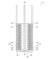
- FIG. 1 is a schematic front view conceptually illustrating an example of a metal-air secondary battery of the present invention.
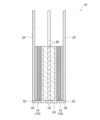
- 2 is a cross-sectional view of the metal-air secondary battery shown in FIG. 1 taken along line 2-2.
- 3 is a cross-sectional view of the metal-air secondary battery shown in FIG. 1 taken along line 3-3.
- 4 is a cross-sectional view of the metal-air secondary battery shown in FIG. 1 taken along line 4-4.
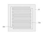
- FIG. 2 is a schematic front view showing an example of a holding member used in the metal-air secondary battery shown in FIG. 1 .
- FIG. 2 is a schematic front view showing the metal-air secondary batteries produced in Examples 1 and 2.
- 7 is a cross-sectional view of the metal-air secondary battery shown in FIG. 6 taken along line 7-7.
- FIG. 8 is a cross-sectional view of the metal-air secondary battery shown in FIG. 6 taken along line 8-8.
- 9 is a cross-sectional view of the metal-air secondary battery shown in FIG. 6 taken along line 9-9.
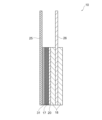
- FIG. 2 is a schematic cross-sectional view showing a metal-air secondary battery produced in Example 3 (Comparative Example). 1 is a graph showing changes in discharge potential measured in a charge-discharge test performed on the metal-air secondary batteries produced in Examples 1 to 3.
- FIG. 1 shows an example of a metal-air secondary battery of the present invention.
- the metal-air secondary battery 10 shown in FIG. 1 includes a charge air electrode layer 12, a discharge air electrode layer 14, a metal anode layer 18, an electrolyte (not shown), and a separator 20.
- the charge air electrode layer 12 and the discharge air electrode layer 14 are both comb-shaped and are spaced apart from each other and interdigitated in the same plane.
- the combination of the charge air electrode layer 12 and the discharge air electrode layer 14 in the same plane is referred to as a composite air electrode layer 16 in this specification.
- the charge air electrode layer 12 includes a charge air electrode catalyst, a conductive material, a binder, and optionally a hydroxide ion conductive material.
- the discharge air electrode layer 14 includes a discharge air electrode catalyst, which is a carbon-based catalyst, a binder, and optionally a hydroxide ion conductive material.
- the metal anode layer 18 is provided opposite the composite air electrode layer 16.
- the metal anode layer 18 is impregnated with an electrolyte.
- the separator 20 is interposed between the composite air electrode layer 16 and the metal negative electrode layer 18 so as to be in contact with the composite air electrode layer 16, isolating the composite air electrode layer 16 from the metal negative electrode layer 18 while allowing hydroxide ion conduction.
- a conductive material e.g., carbon
- a charging catalyst e.g., a hydroxide ion conductive material
- a discharge catalyst e.g., a carbon-based catalyst
- the charging potential overlaps with the oxidation potential of carbon, making the carbon-based catalyst more likely to oxidize and deteriorate. It is believed that the oxidation and deterioration of this carbon-based catalyst leads to a decrease in discharge potential and an increase in overvoltage.
- the charging air electrode layer 12 and the discharge air electrode layer 14 are arranged in a comb-like shape that is spaced apart from each other and interdigitated with each other in the same plane, so that the discharge air electrode catalyst (carbon-based catalyst) can be prevented from being exposed to the charging potential, and the oxidation and deterioration of the carbon-based catalyst can be suppressed.
- the discharge air electrode catalyst carbon-based catalyst
- the region of the charge air electrode layer 12 and the region of the discharge air electrode layer 14 are separated from each other even though they are in the same plane, the region of the discharge air electrode layer 14 is not exposed to the charge potential even while the charge reaction is taking place in the region of the charge air electrode layer 12, and the oxidation and deterioration of the carbon-based catalyst are less likely to progress.
- the decrease in discharge potential and the increase in overvoltage are suppressed.
- the charging air electrode layer 12 includes a charging air electrode catalyst, a conductive material, a binder, and optionally a hydroxide ion conductive material.
- the charging air electrode catalyst has a spherical, plate-like, or fibrous form and is dispersed in the charging air electrode layer 12.
- the charging air electrode catalyst may also serve as a conductive material or a hydroxide ion conductive composite material.
- the charging air electrode catalyst is not particularly limited as long as it has catalytic activity for the charging reaction, but may be a hydroxide catalyst, an oxide catalyst, or a carbon-based catalyst, and is preferably a layered double hydroxide (LDH).
- LDH layered double hydroxide
- the LDH as the charging air electrode catalyst is preferably an LDH containing at least Ni and Fe as constituent elements (Ni-Fe-LDH), and more preferably an LDH containing at least Ni, Fe, V, and Co as constituent elements (Ni-Fe-V-Co-LDH).
- "contained as a constituent element” does not include elements contained as impurities, and refers to the metal elements or metal ions that constitute the hydroxide base layer that constitutes the LDH.
- the charging air electrode catalyst is preferably in the form of fine particles to increase the reaction field. Specifically, the particle size of the charging air electrode catalyst is preferably 5 ⁇ m or less, more preferably 0.5 nm to 3 ⁇ m, and even more preferably 1 nm to 3 ⁇ m.
- the discharge air electrode layer 14 contains a discharge air electrode catalyst, which is a carbon-based catalyst, a binder, and, if desired, a hydroxide ion conductive material.
- the discharge air electrode catalyst has a spherical, plate-like, or fibrous form, and is dispersed in the discharge air electrode layer 14.
- the discharge air electrode catalyst may also serve as a conductive material or a hydroxide ion conductive composite material.
- the discharge air electrode catalyst is not particularly limited as long as it is a carbon-based catalyst that has catalytic activity for the discharge reaction.
- carbon-based catalyst means a catalyst containing carbon, and may be carbon that itself has catalytic activity, or carbon that supports a metal or oxide that has catalytic activity.
- a preferred example of a carbon-based catalyst is carbon powder that supports a catalyst.
- catalysts supported on carbon powder include (i) transition metal elements such as cobalt and nickel, (ii) platinum group elements such as palladium and platinum, (iii) perovskite oxides containing transition metals such as cobalt, manganese, and iron, (iv) precious metal oxides such as ruthenium and palladium, (v) manganese oxide, and (vi) any combination thereof.
- Platinum group elements such as palladium and platinum are particularly preferred, and platinum is the most preferred.
- Another preferred example of a carbon-based catalyst is a carbon powder catalyst in which the carbon itself has discharge activity.
- Examples of such carbon include (i) nitrogen-doped carbon, (ii) nitrogen-phosphorus-doped carbon, (iii) nitrogen-boron-doped carbon, (iv) nitrogen-sulfur-doped carbon, and (v) any combination thereof. Nitrogen-doped carbon and nitrogen-boron-doped carbon are particularly preferred, and nitrogen-doped carbon is the most preferred. It is desirable for the discharge air electrode catalyst to be in the form of fine particles in order to increase the reaction field. Specifically, the particle size of the discharge air electrode catalyst is preferably 5 ⁇ m or less, more preferably 0.5 nm to 3 ⁇ m, and even more preferably 1 nm to 1 ⁇ m.
- the conductive material contained in the charging air electrode layer 12 is not particularly limited as long as it is a material capable of imparting conductivity to the charging air electrode layer 12, but is preferably a carbon-based material, a conductive oxide, or a metal.
- carbon-based materials include carbon black, graphite, carbon nanotubes, graphene, reduced graphene oxide, Ketjen black, and any combination thereof.
- the conductive oxide is preferably a conductive ceramic, and preferred examples of conductive ceramics include LaNiO 3 , LaSr 3 Fe 3 O 10 , and the like.
- Preferred examples of metals include nickel, titanium, and the like.
- a conductive material is not essential, but may be added separately from the carbon-based catalyst.
- the conductive material is preferably a carbon-based material.
- Examples of carbon-based materials include carbon black, graphite, carbon nanotubes, graphene, reduced graphene oxide, Ketjen black, and any combination thereof.
- a known binder resin can be used as the binder contained in the charging air electrode layer 12 and the discharging air electrode layer 14.
- binder resins include acrylic ester resins, butyral resins, vinyl alcohol resins, celluloses, vinyl acetal resins, polytetrafluoroethylene, polyvinylidene fluoride, and any combination thereof, and preferably acrylic ester resins, butyral resins, polytetrafluoroethylene, polyvinylidene fluoride, and any combination thereof.
- the binder is preferably present so as to bind the air electrode catalyst, the conductive material, and the optional hydroxide ion conductive composite material to each other and to adequately expose these components so that they can come into contact with air.
- the charge air electrode layer 12 and/or the discharge air electrode layer 14 may contain a hydroxide ion conductive material as desired.
- the hydroxide ion conductive material has a spherical, plate-like, or strip-like shape, and forms a conductive path throughout the catalyst layer.
- the hydroxide ion conductive material is not particularly limited as long as it has hydroxide ion conductivity, but is preferably an LDH.
- the composition of the LDH is not particularly limited, but it is preferably one having a basic composition of the general formula: M 2+ 1-x M 3+ x (OH) 2 A n- x/n ⁇ mH 2 O (wherein M 2+ is at least one or more divalent cations, M 3+ is at least one or more trivalent cations, A n- is an n-valent anion, n is an integer of 1 or more, x is 0.1 to 0.4, and m is any real number).
- M2 + may be any divalent cation, with preferred examples including Ni2 + , Mg2 + , Ca2 + , Mn2 + , Fe2 + , Co2 + , Cu2 + , and Zn2 + .
- M3+ may be any trivalent cation, with preferred examples including Fe3 + , Al3 + , Co3 + , Cr3 + , and In3 + .
- M2 + and M3 + are each a transition metal ion.
- M 2+ is a divalent transition metal ion such as Ni 2+ , Mn 2+ , Fe 2+ , Co 2+ , Cu 2+ , and particularly preferred Ni 2+
- M 3+ is a trivalent transition metal ion such as Fe 3+ , Co 3+ , Cr 3+ , and particularly preferred Fe 3+
- a part of M 2+ may be substituted with a metal ion other than the transition metal such as Mg 2+ , Ca 2+ , Zn 2+
- a part of M 3+ may be substituted with a metal ion other than the transition metal such as Al 3+ , In 3+ .
- a n- can be any anion, but preferred examples include NO 3- , CO 3 2- , SO 4 2- , OH - , Cl - , I - , Br - , and F - , and is more preferably NO 3 - and/or CO 3 2- .
- M 2+ contains Ni 2+
- M 3+ contains Fe 3+
- a n- contains NO 3 - and/or CO 3 2- .
- n is an integer of 1 or more, but is preferably 1 to 3.
- x is 0.1 to 0.4, but is preferably 0.2 to 0.35.
- m is any real number. More specifically, m is a real number or integer of 0 or more, typically greater than 0 or greater than 1.
- the hydroxide ion conductive material may be a hydroxide ion conductive composite material including hydrophilic fibers and a plurality of hydroxide ion conductive particles supported on the surface of the hydrophilic fibers in a connected state.
- the "a plurality of hydroxide ion conductive particles supported on the surface of the hydrophilic fibers in a connected state" may be specified as a hydroxide ion conductive particle supported on the surface of the hydrophilic fibers that is in contact with adjacent hydroxide ion conductive particles at at least one or more points.
- the hydrophilic fiber is not particularly limited as long as a hydroxyl group (OH group) is coordinated or can be coordinated on the surface of the hydrophilic fiber.
- hydroxide ion conductive particles e.g., LDH platelet particles
- hydroxide ion conductive particles can be synthesized and supported on the surface of the hydrophilic fibers by a coprecipitation method or the like so as to be connected to each other (e.g., so that the faces of the LDH platelet particles are parallel to each other). That is, by using the hydrophilic fibers, it is possible to make the hydroxide ion conductive particles (e.g., LDH platelet particles) into a continuum (i.e., an assembly of particles continuously connected to each other in a planar direction).
- hydrophilic fibers include cellulose nanofibers, chitin nanofibers, chitosan nanofibers (CNF), and combinations thereof, and more preferably cellulose nanofibers (CNF).
- the length of the hydrophilic fibers is not particularly limited, but is preferably 0.1 to 100 ⁇ m, more preferably 0.1 to 50 ⁇ m, even more preferably 0.2 to 50 ⁇ m, particularly preferably 5 to 50 ⁇ m, and most preferably 10 to 50 ⁇ m. That is, hydrophilic fibers can be used from short fiber lengths (e.g., several hundreds of nm) to long fiber lengths (e.g., several tens of ⁇ m) depending on the size of the raw material to be obtained, but long fiber lengths are preferred.
- the hydroxide ion conductive particles are not particularly limited as long as they are particles having hydroxide ion conductivity, but as described above, they are preferably composed of layered double hydroxides (LDHs). In this case, the hydroxide ion conductive particles may be LDH plate-like particles.
- the LDH constituting the hydroxide ion conductive particles preferably contains at least two elements selected from the group consisting of Ni, Fe, Mg, Al, and Ti as components, and more preferably, these at least two elements contain Mg and Al.
- Mg and Al By containing at least two elements, Mg and Al, better anion conductivity (e.g., hydroxide ion conductivity) can be realized.
- the atomic ratio of Al/Mg of Mg-Al-LDH determined by energy dispersive X-ray spectroscopy (EDX) is preferably 0.30 to 0.55, more preferably 0.40 to 0.55.
- the hydroxide ion conductivity can be particularly effectively improved, and as a result, a further increase in the reaction rate of the charge/discharge reaction and a further decrease in the charge/discharge overvoltage can be realized.
- the anion between the layers of the LDH is a hydroxide ion.
- LDH is preferably represented by the general formula [M 2+ 1-x M 3+ x (OH) 2 ][An -x/ n.zH 2 O] (M 2+ includes Mg 2+ , M 3+ includes Al 3+ , An -x/n is OH - , 0.2 ⁇ x ⁇ 0.4, z is any real number exceeding 0).
- LDH can be synthesized by coprecipitation. For example, a raw material aqueous solution containing the constituent elements of LDH may be dropped into an aqueous solution containing carbonate ions and a fiber material such as cellulose nanofiber (CNF) under a condition of pH 9.5 to 12, and hydrothermal treatment may be performed. For example, an aqueous NaOH solution may be used to adjust the pH. The resulting reaction product may be subjected to aging treatment such as stirring, heating, and pressurization as necessary to control the crystal size, crystallinity, and/or orientation.
- CNF cellulose nanofiber
- the charge air electrode layer 12 and/or the discharge air electrode layer 14 contain a hydroxide ion conductive material, the content is preferably an amount that allows an ion conductive path to be formed within the charge air electrode layer 12.
- the charge air electrode layer 12 or the discharge air electrode layer 14 can be manufactured by preparing a paste containing an air electrode catalyst, a binder, and optionally a conductive material and/or a hydroxide ion conductive material, and applying it to the surface of a hydroxide ion conductive separator such as an LDH separator.
- the paste can be prepared by adding an organic polymer (binder resin) and an organic solvent to a mixture containing an air electrode catalyst and optionally a conductive material and/or a hydroxide ion conductive material, and using a known kneading machine such as a three-roll mill or a jet mill.
- organic solvents include alcohols such as butyl carbitol and terpineol, and acetate ester solvents such as butyl acetate.
- the paste can be applied to the hydroxide ion conductive separator in a comb-like pattern by printing. This printing can be performed by various known printing methods, but is preferably performed by screen printing. Alternatively, a clay-like mixture containing an air electrode catalyst, a binder, and optionally a conductive material and/or a hydroxide ion conductive material may be prepared, rolled using a roll press or the like, and the resulting rolled sheet may be dried and then processed into a comb-like shape using a laser processing machine or the like.
- the charge air electrode layer 12 and the discharge air electrode layer 14 are both arranged in a comb-teeth shape.
- the charge air electrode layer 12 and the discharge air electrode layer 14 each have a busbar air electrode 12a, 14a and a plurality of air electrode fingers 12b, 14b extending from the busbar air electrodes 12a, 14a in a comb-teeth shape.
- the plurality of air electrode fingers 12b, 14b are arranged to be spaced apart from each other and interdigitated in the same plane.
- the plurality of air electrode fingers 12b, 14b are arranged so that the air electrode fingers 12b of the charge air electrode layer 12 and the air electrode fingers 14b of the discharge air electrode layer 14 alternate in a direction perpendicular to the extension direction of the air electrode fingers 12b, 14b.
- the width W of each of the air electrode fingers 12b, 14b of the charge air electrode layer 12 or the discharge air electrode layer 14 is not particularly limited as long as charging and discharging are possible, but it is desirable that there is less comb-tooth-shaped segregation of zinc produced during charging and zinc oxide produced during discharging in the metal negative electrode layer 18 provided opposite the composite air electrode layer 16 (i.e., the charge air electrode layer 12 and the discharge air electrode layer 14).
- the width W of each of the air electrode fingers 12b, 14b is preferably 8 mm or less, more preferably 0.05 to 5 mm, and even more preferably 0.1 to 4 mm.
- a charge reaction occurs in the negative electrode portion of the metal negative electrode layer 18 facing the charge air electrode layer 12, and a discharge reaction occurs in the negative electrode portion facing the discharge air electrode layer 14.
- the width W of the air electrode fingers 12b and 14b can be set to a suitable width as described above, the charge and discharge reaction can be continued using the negative electrode active material in the negative electrode portion away from the negative electrode portion facing each of the air electrode fingers 12b and 14b.
- the air electrode fingers 12b, 14b of the charge air electrode layer 12 or the discharge air electrode layer 14 are not particularly limited as long as they are arranged to be spaced apart and interdigitated with each other, but it is preferable that there is less comb-shaped segregation of zinc produced during charging and zinc oxide produced during discharging in the metal negative electrode layer 18.
- the separation distance D between adjacent air electrode fingers 12b, 14b i.e., the distance from the side end of the charge air electrode finger 12b to the side end of the discharge air electrode finger 14b
- the separation distance D between adjacent air electrode fingers 12b, 14b is preferably 4 mm or less, more preferably 0.05 to 3 mm, and even more preferably 0.1 mm to 2 mm.
- the composite air electrode layer 16 refers to a combination consisting of a charge air electrode layer 12 and a discharge air electrode layer 14 in the same plane.
- the charge air electrode layer 12 and the discharge air electrode layer 14 are both comb-shaped and are spaced apart from each other and arranged to interdigitate in the same plane, so they are not in contact with each other. For this reason, the composite air electrode layer 16 is not a single continuous layer, but rather a combination of a pair of charge air electrode layers 12 and discharge air electrode layers 14 that are spaced apart from each other.
- the metal anode layer 18 is provided opposite the composite air cathode layer 16.
- the metal anode layer 18 may be selected from metal anodes of known composition according to the type of metal-air secondary battery.
- the metal anode layer 18 contains at least one selected from the group consisting of zinc, zinc oxide, zinc alloys, and zinc compounds. That is, zinc may be contained in any form of zinc metal, zinc compound, or zinc alloy, so long as it has electrochemical activity suitable for the anode.
- Preferred examples of anode materials include zinc oxide, zinc metal, calcium zincate, etc., and a mixture of zinc metal and zinc oxide is more preferred.
- the metal anode layer 18 may be configured in a clay-like or gel-like form, or may be mixed with an electrolyte to form an anode composite.
- a gelled anode can be easily obtained by adding an electrolyte and a thickener to the anode active material.
- the metal negative electrode layer 18 is impregnated with an electrolyte (not shown). If the separator 20 is a liquid-permeable separator (i.e., if it is not a liquid-impermeable hydroxide ion conductive separator), the separator 20 and the composite air electrode layer 16 are also impregnated with the electrolyte.
- the electrolyte various aqueous electrolytes, particularly alkaline electrolytes, commonly used in metal-air secondary batteries such as zinc-air secondary batteries can be used. Examples of such electrolytes include aqueous alkali metal hydroxide solutions such as potassium hydroxide and sodium hydroxide, and aqueous solutions containing zinc chloride or zinc perchlorate.
- aqueous alkali metal hydroxide solutions particularly potassium hydroxide
- potassium hydroxide solutions with a concentration of 6 to 9 mol/L are preferred.
- zinc compounds such as zinc oxide and zinc hydroxide may be dissolved in the electrolyte.
- zinc oxide may be dissolved in the electrolyte until it is saturated.
- the separator 20 is interposed between the composite air electrode layer 16 and the metal negative electrode layer 18 so as to be in contact with the composite air electrode layer 16, isolating the composite air electrode layer 16 from the metal negative electrode layer 18 while allowing hydroxide ion conduction.
- the separator 20 is not particularly limited as long as it can avoid electrical contact between the composite air electrode layer 16 and the metal negative electrode layer 18 and allows hydroxide ions to pass between the composite air electrode layer 16 and the metal negative electrode layer 18, and various separators such as a microporous membrane separator, a nonwoven fabric separator, a cellulose separator, and a hydroxide ion conductive separator described below can be used.
- a preferred separator 20 is a hydroxide ion conductive separator.
- a hydroxide ion conductive separator is defined as a separator that contains a hydroxide ion conductive solid electrolyte and selectively passes hydroxide ions solely by utilizing hydroxide ion conductivity.
- a preferred hydroxide ion conductive solid electrolyte is a layered double hydroxide (LDH) and/or an LDH-like compound.
- LDH layered double hydroxide
- the hydroxide ion conductive separator is preferably an LDH separator.
- an "LDH separator” is defined as a separator that contains LDH and/or an LDH-like compound and selectively passes hydroxide ions solely by utilizing the hydroxide ion conductivity of LDH and/or an LDH-like compound.
- an "LDH-like compound” is a hydroxide and/or oxide of a layered crystal structure that may not be called LDH but has hydroxide ion conductivity, and can be said to be equivalent to LDH.
- LDH can be interpreted as including not only LDH but also LDH-like compounds.
- the LDH separator is preferably composited with a porous substrate.
- the LDH separator preferably further comprises a porous substrate, and is composited with the porous substrate in a form in which the pores of the porous substrate are filled with the LDH and/or LDH-like compound. That is, in a preferred LDH separator, the pores of the porous substrate are blocked with the LDH and/or LDH-like compound so as to exhibit hydroxide ion conductivity and gas impermeability (and therefore function as an LDH separator exhibiting hydroxide ion conductivity).
- the porous substrate is preferably made of a polymeric material, and it is particularly preferred that the LDH and/or LDH-like compound is incorporated throughout the entire thickness of the porous substrate made of a polymeric material.
- LDH separators such as those disclosed in Patent Documents 1 to 10 can be used.
- the thickness of the LDH separator is preferably 5 to 100 ⁇ m, more preferably 5 to 80 ⁇ m, even more preferably 5 to 60 ⁇ m, and particularly preferably 5 to 40 ⁇ m.
- the separator 20 is a hydroxide ion conductive separator (e.g., an LDH separator)
- the charge air electrode layer 12 contains a hydroxide ion conductive material
- the discharge air electrode layer 14 contains a hydroxide ion conductive material.
- the hydroxide ion conductive materials that can be used for the air electrode layers 12 and 14 are as described above. That is, a hydroxide ion conductive separator (e.g., an LDH separator) has a dense structure that does not allow the electrolyte to pass through, so the hydroxide ion conductive separator prevents the electrolyte from penetrating into the composite air electrode layer 16, and no electrolyte is present in the composite air electrode layer 16.
- the electrolyte cannot be used as a hydroxide ion conductive medium in the composite air electrode layer 16.
- a hydroxide ion conductive path can be secured by including a hydroxide ion conductive material in the charge air electrode layer 12 and the discharge air electrode layer 14.
- the separator 20 is a hydroxide ion conductive separator (e.g., an LDH separator)
- the separator 20 is preferably provided so as to cover not only both sides of the metal negative electrode layer 18 but also the end faces (excluding the upper end face) as shown in Figures 2 to 4.
- a hydroxide ion conductive separator e.g., an LDH separator
- the metal-air secondary battery 10 includes a pair of composite air electrode layers 16 that face each other at a distance, a separator 20 is interposed between each of the pair of composite air electrode layers 16 and the metal negative electrode layer 18, and the metal negative electrode layer 18 is sandwiched between the pair of composite air electrode layers 16 via the separator 20.
- the metal-air secondary battery 10 of the present invention is not limited to this embodiment, and may be configured such that the composite air electrode layer 16 is provided on only one side of the metal negative electrode layer 18, as shown in Figures 6 to 9 described later.
- the charging air electrode current collector 22 is provided on the outside of the charging air electrode layer 12 so as to extend (e.g., upward or sideways) from the end of the charging air electrode layer 12, while the discharging air electrode current collector 24 is provided on the outside of the discharging air electrode layer 14 so as to extend (e.g., upward or sideways) from the end of the discharging air electrode layer 14.
- the air electrode current collectors 22, 24 are preferably arranged in a comb-like shape on the comb-like parts of the air electrode layers 12, 14 as well.
- the air electrode current collectors 22, 24 can be made of a porous material having general electrical conductivity, and are preferably made of metal.
- Preferred examples of the metal constituting the air electrode current collectors 22, 24 include stainless steel, titanium, nickel, brass, copper, etc.
- the shape of the air electrode current collectors 22, 24 is not particularly limited as long as electrical conductivity and air permeability can be ensured, but preferred examples include porous metal, metal mesh, and uneven metal plate.
- porous metals include metal products with open pores, such as metal foam and sintered porous metal.
- metal meshes include laminated products of metal meshes, or metal meshes in a laminated form. As metal plates with an uneven shape, porous metal plates such as punched metals that have been processed into a corrugated shape may also be used.
- a negative electrode collector 26 is provided that supports the metal negative electrode layer 18 and extends (e.g., upward or sideways) from the end of the metal negative electrode layer 18.
- the negative electrode collector include metal plates or meshes of stainless steel, copper (e.g., copper punched metal), nickel, etc., carbon paper, and oxide conductors.
- a mixture containing zinc oxide powder and/or zinc powder, and optionally a binder (e.g., polytetrafluoroethylene particles) can be applied to copper punched metal to preferably produce a negative electrode plate consisting of the metal negative electrode layer 18/negative electrode collector 26.
- a charging gas diffusion electrode 28 may be provided between the charging air electrode layer 12 and the charging air electrode current collector 22, while a discharge gas diffusion electrode 30 may be provided between the discharging air electrode layer 14 and the discharging air electrode current collector 24.
- the gas diffusion electrodes 28, 30 are preferably arranged in a comb-like shape on the comb-like parts of the air electrode layers 12, 14 as well.
- the gas diffusion electrodes 28, 30 include a microporous layer (MPL) and a gas diffusion substrate, and are preferably formed on one side of the air electrode layers 12, 14 so that the microporous layer (MPL) is in contact with the air electrode layers 12, 14.
- the gas diffusion substrate is not particularly limited as long as it is a porous material that has electronic conductivity and can diffuse oxygen throughout the electrode, but carbon paper or a porous metal body is preferable.
- the thickness of the gas diffusion substrate is preferably 0.4 ⁇ m or less from the viewpoint of reducing the energy density while ensuring gas diffusibility, and more preferably 0.1 to 0.3 ⁇ m.
- the porosity of the gas diffusion substrate is preferably 70% or more, more preferably 70 to 90%, and particularly preferably 75 to 85%, from the viewpoint of the amount of gas permeation. With the above porosity, excellent gas diffusion can be ensured and a wide reaction area can be ensured. In addition, since there is a large amount of space in the pores, clogging with the generated water is unlikely to occur.
- the porosity can be measured by mercury intrusion porosimetry.
- the microporous layer is not particularly limited as long as it has electronic conductivity and water repellency to such an extent that the water generated in the air electrode reaction does not penetrate into the gas diffusion substrate, but it is preferable that the microporous layer contains a carbon material and polytetrafluoroethylene (PTFE).
- the air electrode layers 12, 14 preferably include comb-shaped portions, and the gas diffusion electrodes 28, 30 and/or the air electrode current collectors 22, 24 are preferably arranged in a comb-shaped manner in the comb-shaped portions.
- the metal-air secondary battery 10 preferably has a holding member 32 having a comb-shaped opening 32a that can accommodate the comb-shaped air electrode layers 12, 14, the comb-shaped gas diffusion electrodes 28, 30, and/or the comb-shaped air electrode current collectors 22, 24.
- the comb-shaped air electrode layers 12, 14, the comb-shaped gas diffusion electrodes 28, 30, and/or the comb-shaped air electrode current collectors 22, 24 are fitted into the comb-shaped opening 32a, and the metal-air secondary battery 10 can be easily assembled.
- each component in the assembled metal-air secondary battery 10 can be reliably fixed by the holding member 32.
- the material of the holding member 32 is not particularly limited as long as it is an insulating material, but is preferably an elastic material having insulating properties such as a rubber sheet.
- a holding member 32 made of an elastic material such as a rubber sheet When a holding member 32 made of an elastic material such as a rubber sheet is used, pressure can be applied to each component of the metal-air secondary battery 10 so as to bring the composite air electrode layer 16, the separator 20, and the metal anode layer 18 into close contact with each other, which has the advantage of lowering the battery resistance and making it easier to improve the performance of the metal-air secondary battery 10.
- the comb-shaped air electrode layers 12, 14, comb-shaped gas diffusion electrodes 28, 30, and/or comb-shaped air electrode current collectors 22, 24 fitted into the holding member 32 have the advantage of being able to maintain a shape that allows gas diffusion (without excessive deformation of the shape) while maintaining suitable electronic conduction contact due to the elasticity of the material such as a rubber sheet.
- the metal-air secondary battery according to the present invention is not particularly limited in type as long as it is an air secondary battery that uses a metal negative electrode, but a zinc-air secondary battery that uses a zinc electrode as the metal negative electrode is particularly preferred. It may also be a lithium-air secondary battery that uses a lithium electrode as the metal negative electrode.
- Example 1 Example using nonwoven fabric separator A metal-air secondary battery 10 having the configuration shown in Figs. 6 to 9 and using a nonwoven fabric separator as the separator 20 was fabricated as follows and evaluated.
- the obtained charging air electrode layer 12 and a charging gas diffusion electrode 28 (SIGRACET29BC) were stacked, pressed with a uniaxial press machine, and then dried in a vacuum dryer at 80 ° C. for 14 hours. After drying, the air electrode fingers 12b were processed using a laser processing machine into a comb-like shape with a width of 8 mm and a spacing of 16 mm between the air electrode fingers 12b, thereby obtaining a charging comb-like laminate consisting of a charging air electrode layer 12 and a charging gas diffusion electrode 28.
- each air electrode finger 14b was 8 mm, and the air electrode fingers 14b were processed into a comb-like shape with a separation distance of 16 mm with a laser processing machine, and a discharge comb-like laminate consisting of the discharge air electrode layer 14 and the discharge gas diffusion electrode 30 was obtained.
- the obtained kneaded product was rolled with a roll press to obtain a negative electrode active material sheet with a thickness of 0.2 mm.
- This negative electrode active material sheet was placed on both sides of a tin-plated copper expand metal and pressed, and then dried at 80 ° C. for 14 hours in a vacuum dryer.
- the dried negative electrode sheet was cut to a size of 2 cm square where the active material was applied, and copper foil was welded to the end of the copper expand metal to obtain a negative electrode structure consisting of a zinc oxide negative electrode as the metal negative electrode layer 18 and copper expand metal and copper foil as the negative electrode current collector 26.
- a rubber sheet having two comb-shaped openings 32a capable of accommodating the charge comb-teeth laminate and the discharge comb-teeth laminate so as to be spaced apart from each other and interdigitated with each other was prepared as the holding member 32.
- the charge air electrode current collector 22 (nickel mesh) having the charge comb-teeth laminate and a comb-teeth portion corresponding thereto was fitted into the opening 32a of this rubber sheet, and the discharge air electrode current collector 24 (nickel mesh) having the discharge comb-teeth laminate and a comb-teeth portion corresponding thereto was fitted into the other opening 32a.
- the width W of each of the air electrode fingers 12b, 14b was 8 mm, and the distance D between adjacent air electrode fingers 12b, 14b was 4 mm.
- a nonwoven fabric (FT-7040P, manufactured by Nippon Vilene Co., Ltd.) was placed as a separator 20 on one side of the metal negative electrode layer 18, and a rubber sheet into which a charging comb-like laminate and a discharging comb-like laminate were fitted was placed on the side of the nonwoven fabric that was not in contact with the negative electrode structure.
- the laminate thus obtained was sandwiched between a pressing tool with a sealing member tightly biting the outer periphery of the nonwoven fabric, and firmly fixed with a screw.
- This pressing tool has an oxygen inlet on the comb-like laminate side and a liquid injection port through which an electrolyte can be introduced on the negative electrode structure side.
- a 5.4 M KOH aqueous solution saturated with zinc oxide was added through the liquid injection port of the assembly thus obtained to prepare an evaluation cell.
- Example 2 Example using hydroxide ion conductive separator A metal-air secondary battery 10 having the configuration shown in Figs. 6 to 9 and using an LDH separator as the separator 20 was fabricated as follows and evaluated.
- This paste was applied by screen printing to the surface of an LDH separator (a polyethylene microporous membrane in which an Mg-Al-Ti-Y-LDH-like compound was precipitated by hydrothermal synthesis in the pores and on the surface and roll-pressed, thickness: 20 ⁇ m) as the separator 20 to form a comb-like shape with an electrode width of 10 mm and an interelectrode distance of 20 mm, to form a charging air electrode layer 12.
- a charging gas diffusion electrode 28 SIGRACET29BC
- a charging comb-like laminate composed of the charging air cathode layer 12 and the charging gas diffusion electrode 28 was obtained.
- a discharge gas diffusion electrode 30 (SIGRACET29BC) having the same comb-like shape was placed on the discharge air electrode layer 14.
- the laminate thus obtained was placed under a weight and dried in a vacuum dryer at 80°C for 30 minutes to form a discharge comb-shaped laminate consisting of a discharge air electrode layer 14 and a discharge gas diffusion electrode 30.
- a composite air electrode layer/separator assembly was obtained that had a comb-shaped composite air electrode layer 16 and gas diffusion electrodes 28, 30 on the separator 20.
- a rubber sheet (fluororesin) having two comb-shaped openings 32a capable of accommodating the charge comb-shaped laminate and the discharge comb-shaped laminate in a mutually spaced and interlocking manner was prepared as the holding member 32.
- the charge air electrode current collector 22 and the discharge air electrode current collector 24 (both nickel meshes) having corresponding comb-shaped portions were fitted into the two openings 32a of this rubber sheet, and the positions of the comb-shaped portions were arranged so as to match on the printed surface side of the composite air electrode layer/separator assembly, and the assembly was pressed with a uniaxial press. Then, the negative electrode structure was laminated on the LDH separator side of the composite air electrode layer/separator assembly.
- the laminate thus obtained was sandwiched by a pressing tool in a state in which the sealing member was closely interlocked with the outer periphery of the LDH separator, and was firmly fixed with a screw.
- This pressing tool has an oxygen inlet on the comb-shaped laminate side and a liquid inlet on the negative electrode side through which the electrolyte can be introduced.
- a 5.4 M KOH aqueous solution saturated with zinc oxide was poured into the injection port of the thus obtained assembly to prepare an evaluation cell.
- Example 3 (Comparison) A metal-air secondary battery 10 having the configuration shown in FIG. 10 using an LDH separator as the separator 20 and a flat, non-comb-shaped charge/discharge air electrode layer 17 was fabricated and evaluated as follows.
- This paste was applied by screen printing to the surface of an LDH separator (a polyethylene microporous membrane in which an Mg-Al-Ti-Y-LDH-like compound was precipitated by hydrothermal synthesis and roll-pressed on the pores and surface thereof, thickness: 20 ⁇ m) to form a charge/discharge dual-purpose air electrode layer 17.
- LDH separator a polyethylene microporous membrane in which an Mg-Al-Ti-Y-LDH-like compound was precipitated by hydrothermal synthesis and roll-pressed on the pores and surface thereof, thickness: 20 ⁇ m
- a gas diffusion electrode 31 SIGRACET29BC
- a weight was placed on the laminate thus obtained, and it was dried at 80° C. for 30 minutes in a vacuum dryer, to obtain an air cathode layer/separator assembly including a non-comb-shaped air cathode layer 17 and a gas diffusion electrode 31 on the separator 20.
- Example 1 The charge and discharge characteristics of the evaluation cell were measured in the same manner as in Example 1. The results were as shown in FIG. 11. As can be seen from the results shown in FIG. 11, the evaluation cells according to the present invention prepared in Examples 1 and 2 were able to suppress the initial deterioration associated with the oxidation of the catalyst and showed a high discharge potential, compared to the evaluation cell prepared in Example 3 (Comparative Example). In addition, the fact that they showed a high discharge potential means that the increase in overvoltage was suppressed.
Landscapes
- Chemical & Material Sciences (AREA)
- Chemical Kinetics & Catalysis (AREA)
- Electrochemistry (AREA)
- General Chemical & Material Sciences (AREA)
- Engineering & Computer Science (AREA)
- Materials Engineering (AREA)
- Manufacturing & Machinery (AREA)
- Hybrid Cells (AREA)
Priority Applications (2)
| Application Number | Priority Date | Filing Date | Title |
|---|---|---|---|
| JP2025544263A JPWO2025052966A1 (https=) | 2023-09-06 | 2024-08-23 | |
| CN202480046391.2A CN121773519A (zh) | 2023-09-06 | 2024-08-23 | 金属空气二次电池 |
Applications Claiming Priority (2)
| Application Number | Priority Date | Filing Date | Title |
|---|---|---|---|
| JP2023144307 | 2023-09-06 | ||
| JP2023-144307 | 2023-09-06 |
Publications (1)
| Publication Number | Publication Date |
|---|---|
| WO2025052966A1 true WO2025052966A1 (ja) | 2025-03-13 |
Family
ID=94923712
Family Applications (1)
| Application Number | Title | Priority Date | Filing Date |
|---|---|---|---|
| PCT/JP2024/030060 Pending WO2025052966A1 (ja) | 2023-09-06 | 2024-08-23 | 金属空気二次電池 |
Country Status (3)
| Country | Link |
|---|---|
| JP (1) | JPWO2025052966A1 (https=) |
| CN (1) | CN121773519A (https=) |
| WO (1) | WO2025052966A1 (https=) |
Citations (6)
| Publication number | Priority date | Publication date | Assignee | Title |
|---|---|---|---|---|
| JP2015170400A (ja) * | 2014-03-05 | 2015-09-28 | シャープ株式会社 | 金属空気電池 |
| JP2016028380A (ja) * | 2014-07-10 | 2016-02-25 | 株式会社デンソー | 全固体空気電池 |
| JP2017162773A (ja) * | 2016-03-11 | 2017-09-14 | 株式会社日本触媒 | 金属空気電池 |
| JP2017224437A (ja) * | 2016-06-14 | 2017-12-21 | シャープ株式会社 | 金属空気電池および金属空気組電池 |
| WO2021060119A1 (ja) * | 2019-09-25 | 2021-04-01 | 日本碍子株式会社 | 空気極/セパレータ接合体及び亜鉛空気二次電池 |
| WO2022209010A1 (ja) * | 2021-03-30 | 2022-10-06 | 日本碍子株式会社 | 空気極/セパレータ接合体及び金属空気二次電池 |
-
2024
- 2024-08-23 JP JP2025544263A patent/JPWO2025052966A1/ja active Pending
- 2024-08-23 WO PCT/JP2024/030060 patent/WO2025052966A1/ja active Pending
- 2024-08-23 CN CN202480046391.2A patent/CN121773519A/zh active Pending
Patent Citations (6)
| Publication number | Priority date | Publication date | Assignee | Title |
|---|---|---|---|---|
| JP2015170400A (ja) * | 2014-03-05 | 2015-09-28 | シャープ株式会社 | 金属空気電池 |
| JP2016028380A (ja) * | 2014-07-10 | 2016-02-25 | 株式会社デンソー | 全固体空気電池 |
| JP2017162773A (ja) * | 2016-03-11 | 2017-09-14 | 株式会社日本触媒 | 金属空気電池 |
| JP2017224437A (ja) * | 2016-06-14 | 2017-12-21 | シャープ株式会社 | 金属空気電池および金属空気組電池 |
| WO2021060119A1 (ja) * | 2019-09-25 | 2021-04-01 | 日本碍子株式会社 | 空気極/セパレータ接合体及び亜鉛空気二次電池 |
| WO2022209010A1 (ja) * | 2021-03-30 | 2022-10-06 | 日本碍子株式会社 | 空気極/セパレータ接合体及び金属空気二次電池 |
Also Published As
| Publication number | Publication date |
|---|---|
| CN121773519A (zh) | 2026-03-31 |
| JPWO2025052966A1 (https=) | 2025-03-13 |
Similar Documents
| Publication | Publication Date | Title |
|---|---|---|
| JP6070671B2 (ja) | 空気電池 | |
| EP3167500B1 (de) | Sekundäre elektrochemische zelle | |
| US20190044129A1 (en) | Rechargeable Alkaline Manganese Dioxide-Zinc Bipolar Batteries | |
| US12482807B2 (en) | Rechargeable alkaline battery comprising metal hydroxide separator | |
| KR20200038299A (ko) | 알칼리 배터리에서 선택성 이온 침투를 위한 이온 선택성 막 | |
| US20250015280A1 (en) | Negative electrode and zinc secondary battery | |
| JP7228706B2 (ja) | 空気極/セパレータ接合体及び亜鉛空気二次電池 | |
| WO2019097830A1 (ja) | 空気電池用正極及び空気電池 | |
| JP7382488B2 (ja) | 亜鉛二次電池及びモジュール電池 | |
| US20230261251A1 (en) | Negative electrode and zinc secondary battery | |
| EP3178125B1 (de) | Sekundäre elektrochemische zelle auf basis von nickel / eisen | |
| US20240413486A1 (en) | Zinc secondary battery | |
| US20250015339A1 (en) | Zinc secondary battery | |
| WO2022209010A1 (ja) | 空気極/セパレータ接合体及び金属空気二次電池 | |
| WO2025052966A1 (ja) | 金属空気二次電池 | |
| RU2366039C1 (ru) | Воздушный электрод химического источника тока и способ его изготовления | |
| US20230261204A1 (en) | Negative electrode and zinc secondary battery | |
| JP7773647B2 (ja) | 負極板及び亜鉛二次電池 | |
| WO2016208770A1 (ja) | 空気極材料、空気極及び金属空気電池 | |
| US20250357498A1 (en) | Air electrode/separator conjugate and metal-air rechargeable battery | |
| JP2019117785A (ja) | 空気電池用正極及び空気電池 | |
| JP7557613B2 (ja) | 負極及び亜鉛二次電池 | |
| JP7401071B2 (ja) | 金属空気電池 | |
| JP7626646B2 (ja) | 定置型ニッケル亜鉛二次電池 | |
| JP7516086B2 (ja) | 二次電池及びモジュール電池 |
Legal Events
| Date | Code | Title | Description |
|---|---|---|---|
| 121 | Ep: the epo has been informed by wipo that ep was designated in this application |
Ref document number: 24862618 Country of ref document: EP Kind code of ref document: A1 |
|
| ENP | Entry into the national phase |
Ref document number: 2025544263 Country of ref document: JP Kind code of ref document: A |
|
| WWE | Wipo information: entry into national phase |
Ref document number: 2025544263 Country of ref document: JP |