WO2025047738A1 - 電極および蓄電デバイス - Google Patents
電極および蓄電デバイス Download PDFInfo
- Publication number
- WO2025047738A1 WO2025047738A1 PCT/JP2024/030499 JP2024030499W WO2025047738A1 WO 2025047738 A1 WO2025047738 A1 WO 2025047738A1 JP 2024030499 W JP2024030499 W JP 2024030499W WO 2025047738 A1 WO2025047738 A1 WO 2025047738A1
- Authority
- WO
- WIPO (PCT)
- Prior art keywords
- particles
- active material
- electrode
- cross
- section
- Prior art date
- Legal status (The legal status is an assumption and is not a legal conclusion. Google has not performed a legal analysis and makes no representation as to the accuracy of the status listed.)
- Pending
Links
Images


Classifications
-
- H—ELECTRICITY
- H01—ELECTRIC ELEMENTS
- H01M—PROCESSES OR MEANS, e.g. BATTERIES, FOR THE DIRECT CONVERSION OF CHEMICAL ENERGY INTO ELECTRICAL ENERGY
- H01M10/00—Secondary cells; Manufacture thereof
- H01M10/05—Accumulators with non-aqueous electrolyte
- H01M10/052—Li-accumulators
-
- H—ELECTRICITY
- H01—ELECTRIC ELEMENTS
- H01M—PROCESSES OR MEANS, e.g. BATTERIES, FOR THE DIRECT CONVERSION OF CHEMICAL ENERGY INTO ELECTRICAL ENERGY
- H01M10/00—Secondary cells; Manufacture thereof
- H01M10/05—Accumulators with non-aqueous electrolyte
- H01M10/056—Accumulators with non-aqueous electrolyte characterised by the materials used as electrolytes, e.g. mixed inorganic/organic electrolytes
- H01M10/0561—Accumulators with non-aqueous electrolyte characterised by the materials used as electrolytes, e.g. mixed inorganic/organic electrolytes the electrolyte being constituted of inorganic materials only
- H01M10/0562—Solid materials
-
- H—ELECTRICITY
- H01—ELECTRIC ELEMENTS
- H01M—PROCESSES OR MEANS, e.g. BATTERIES, FOR THE DIRECT CONVERSION OF CHEMICAL ENERGY INTO ELECTRICAL ENERGY
- H01M10/00—Secondary cells; Manufacture thereof
- H01M10/42—Methods or arrangements for servicing or maintenance of secondary cells or secondary half-cells
- H01M10/4235—Safety or regulating additives or arrangements in electrodes, separators or electrolyte
-
- H—ELECTRICITY
- H01—ELECTRIC ELEMENTS
- H01M—PROCESSES OR MEANS, e.g. BATTERIES, FOR THE DIRECT CONVERSION OF CHEMICAL ENERGY INTO ELECTRICAL ENERGY
- H01M4/00—Electrodes
- H01M4/02—Electrodes composed of, or comprising, active material
- H01M4/13—Electrodes for accumulators with non-aqueous electrolyte, e.g. for lithium-accumulators; Processes of manufacture thereof
-
- H—ELECTRICITY
- H01—ELECTRIC ELEMENTS
- H01M—PROCESSES OR MEANS, e.g. BATTERIES, FOR THE DIRECT CONVERSION OF CHEMICAL ENERGY INTO ELECTRICAL ENERGY
- H01M4/00—Electrodes
- H01M4/02—Electrodes composed of, or comprising, active material
- H01M4/62—Selection of inactive substances as ingredients for active masses, e.g. binders, fillers
-
- H—ELECTRICITY
- H01—ELECTRIC ELEMENTS
- H01M—PROCESSES OR MEANS, e.g. BATTERIES, FOR THE DIRECT CONVERSION OF CHEMICAL ENERGY INTO ELECTRICAL ENERGY
- H01M4/00—Electrodes
- H01M4/02—Electrodes composed of, or comprising, active material
- H01M2004/021—Physical characteristics, e.g. porosity, surface area
-
- H—ELECTRICITY
- H01—ELECTRIC ELEMENTS
- H01M—PROCESSES OR MEANS, e.g. BATTERIES, FOR THE DIRECT CONVERSION OF CHEMICAL ENERGY INTO ELECTRICAL ENERGY
- H01M2300/00—Electrolytes
- H01M2300/0017—Non-aqueous electrolytes
- H01M2300/0065—Solid electrolytes
-
- Y—GENERAL TAGGING OF NEW TECHNOLOGICAL DEVELOPMENTS; GENERAL TAGGING OF CROSS-SECTIONAL TECHNOLOGIES SPANNING OVER SEVERAL SECTIONS OF THE IPC; TECHNICAL SUBJECTS COVERED BY FORMER USPC CROSS-REFERENCE ART COLLECTIONS [XRACs] AND DIGESTS
- Y02—TECHNOLOGIES OR APPLICATIONS FOR MITIGATION OR ADAPTATION AGAINST CLIMATE CHANGE
- Y02E—REDUCTION OF GREENHOUSE GAS [GHG] EMISSIONS, RELATED TO ENERGY GENERATION, TRANSMISSION OR DISTRIBUTION
- Y02E60/00—Enabling technologies; Technologies with a potential or indirect contribution to GHG emissions mitigation
- Y02E60/10—Energy storage using batteries
Definitions
- the present invention relates to an electrode and an electricity storage device that contain particles of a solid electrolyte.
- Patent Document 1 discloses prior art that sets the material of the particles and the proportion of particles in the electrode.
- the present invention was made to meet this demand, and aims to provide an electrode and an electricity storage device that can reduce charge transfer resistance.
- a first aspect for achieving this object is an electrode containing solid electrolyte particles, the proportion of the particles being 0.1 vol% or more and 30 vol% or less, and the average distance between particles in an area of 400 ⁇ m2 on the cross section of the electrode where 6 or more particles appear is 1 ⁇ m or more.
- the second embodiment is the first embodiment, in which the average equivalent circle diameter of the particles appearing in the cross section is 10 ⁇ m or less.
- the third embodiment is the first embodiment, in which the average equivalent circle diameter of the particles appearing in the cross section is 5 ⁇ m or less.
- the fourth embodiment is any one of the first to third embodiments, further comprising an active material, the average circle-equivalent diameter of the active material appearing in the cross section being 5 ⁇ m or more.
- the particles are oxides.
- the sixth aspect is the fifth aspect, in which the particles have a garnet-type crystal structure containing Li, La, and Zr.
- the seventh aspect is an electricity storage device that includes an electrode according to any one of the first to sixth aspects.
- the electrode of the present invention contains 0.1 vol% to 30 vol% of solid electrolyte particles, and the average distance between particles in an area of 400 ⁇ m2 on the cross section of the electrode where 6 or more particles appear is 1 ⁇ m or more.
- the number of reaction sites due to the particles dispersed in the electrode can be increased, and the charge transfer resistance can be reduced.
- FIG. 1 is a cross-sectional view of an electricity storage device according to an embodiment.
- FIG. 1 is a diagram illustrating a garnet-type crystal structure.
- FIG. 2 is a cross-sectional view of active material and particles appearing in the area of an active material layer. A cross-sectional view of a particle appearing in the area.
- Fig. 1 is a schematic cross-sectional view of an electricity storage device 10 in one embodiment.
- the electricity storage device 10 includes a positive electrode 11, a negative electrode 15, and a separator 14 that separates the positive electrode 11 from the negative electrode 15.
- Examples of ions (hereinafter referred to as "charge carriers") that move between the positive electrode 11 and the negative electrode 15 through the separator 14 include cations such as Li + , Na + , K + , Mg2 + , Cu + , and Ag + .
- Separator 14 contains an electrolyte through which charge carriers move.
- the electrolyte is appropriately selected from solid, gel, and liquid (electrolyte).
- separator 14 is made of a porous body having electronic insulation properties. Examples of the porous body include nonwoven fabric and porous membranes through which charge carriers pass. Examples of materials for the porous body include cellulose, polypropylene, polyethylene, polyimide, alumina, etc.
- An electrolyte is a solution in which a supporting electrolyte is dissolved in an aqueous or non-aqueous solvent.
- the supporting electrolyte may also be dissolved in a mixed solvent of an aqueous and non-aqueous solvent.
- Non-aqueous solvents are broadly classified into molecular solvents, which are mostly composed of molecules, and ionic liquids, which are composed of cations and anions.
- One of the reasons for using non-aqueous solvents in electrolytes is to make the potential window wider compared to aqueous solvents. Ionic liquids are preferred because they can make the potential window wider compared to aqueous solvents.
- an aprotic solvent is preferable in order to widen the potential window of the electrolyte.
- aprotic solvents include cyclic esters, chain esters, aliphatic carboxylate esters, phosphate esters, nitriles, amides, sulfur compounds, ketones, ethers, nitro compounds, and fluorous solvents. Mixtures of these may also be used.
- Ionic liquids are compounds consisting of cations and anions, and are liquid at room temperature and pressure. If the solvent of an electrolyte is an ionic liquid, the flame retardancy of the electrolyte can be improved. Ionic liquids having one or more cationic species selected from the group consisting of ammonium, imidazolium, pyrrolidinium, and piperidinium are preferred.
- the anion component of the ionic liquid is not particularly limited, and examples of the anion component include inorganic anions such as BF 4 - and N(SO 2 F) 2 - , and organic anions such as B(C 6 H 5 ) 4 - , CH 3 SO 3 - , CF 3 SO 3 - , N(SO 2 CF 3 ) 2 - , and N(SO 2 C 4 F 9 ) 2 - .
- the ionic liquid may be a solvated ionic liquid.
- solvated ionic liquids include those in which a supporting electrolyte is dissolved in a sulfone-based solvent such as sulfolane or a sulfolane derivative, or a glyme-based solvent such as tetraglyme.
- the supporting electrolyte is a lithium salt.
- the anions of the supporting electrolyte are OH - , halide ions (I - , Cl - , Br - , etc.), SCN - , BF 4 - , BF 3 (CF 3 ) - , BF 3 (C 2 F 5 ) - , PF 6 - , ClO 4 - , SbF 6 - , N(SO 2 F) 2 - , N(SO 2 CF 3 ) 2 - , N(SO 2 C 2 F 5 ) 2 - , B(C 6 H 5 ) 4 - , B(O 2 C 2 H 4 ) 2 - , C(SO 2 F) 3 - , C(SO 2 CF 3 ) 3 - , CF 3 COO - , CF Examples include 3SO2O- , C6F5SO2O-, B ( O2C2O2 )
- the concentration of the supporting electrolyte in the electrolyte solution is 0.2 mol/dm 3 or more, preferably 0.5 mol/dm 3 or more, more preferably 1.0 mol/dm 3 or more.
- concentration of the supporting electrolyte increases, so that the amount of uncoordinated solvent decreases, and coordination by counter anions (so-called ionic association) is predominant. This suppresses the reductive decomposition of the electrolyte solution, while increasing the oxidation potential and widening the potential window.
- the concentration of the supporting electrolyte is preferably 4.0 mol/dm 3 or less, more preferably 2.0 mol/dm 3 or less. This is because when the concentration of the supporting electrolyte exceeds 4.0 mol/dm 3 , the ionic conductivity tends to decrease significantly due to the increase in the viscosity of the electrolyte solution.
- the solid or gel electrolyte includes one or more selected from sulfides, oxides, hydrides, halides, and organic electrolytes.
- Examples of the separator 14 include sintered bodies containing these electrolytes, compacts formed by compressing an assembly of electrolyte particles, and mixtures of electrolyte particles and an electrolytic solution.
- Examples of sulfide-based electrolytes include crystalline thiolicon-type, glass and glass ceramic-type electrolytes such as Li 10 GeP 2 S 12 type, argyrodite type, Li 7 P 3 S 11 type, and Li 2 S-P 2 S 5.
- Examples of oxide-based electrolytes include NASICON-based materials, LISICON-based materials, oxides having a perovskite structure, and oxides having a garnet structure.
- Examples of hydride electrolytes include solid solutions of LiBH4 with lithium halide compounds (LiI, LiBr, LiCl) and lithium amide ( LiNH2 ).
- Examples of halide solid electrolytes include Li3YCl6 .
- Examples of organic solid electrolytes include polyethylene oxide, polypropylene oxide, and polyacrylonitrile.
- NASICON-based materials are materials expressed by the general formula A x M 2 (TO 4 ) 3.
- A include Na and Li
- examples of M include Zr, Ti, V, Mn, Cr, Fe, Ni, Al, and Ge
- examples of T include P, Si, and As, such as Na 3 V 2 (PO 4 ) 3 , Li 1+x Al x Ti 2-x (PO 4 ) 3 , and Li 1+x Ge x Ti 2-x (PO 4 ) 3.
- An example of a LISICON-based material is Li 4-2x Zn x GeO 4 (0 ⁇ x ⁇ 1).
- oxides having a perovskite structure include Li x La (1-x)/3 NbO 3 and La 2/3-x Li 3x TiO 3 (0 ⁇ x ⁇ 1).
- the positive electrode 11 is made up of a current collector 12 and an active material layer 13 stacked together.
- the current collector 12 is a conductive member. Examples of materials for the current collector 12 include metals selected from Ni, Ti, Fe, and Al, alloys containing two or more of these elements, stainless steel, and carbon materials.
- the active material layer 13 includes an active material and solid electrolyte particles.
- the active material include a metal oxide having a transition metal, a sulfur-based active material, and an organic active material.
- the charge carrier is Li +
- examples of the metal oxide having a transition metal include a metal oxide containing one or more elements selected from Mn, Co, Ni, Fe, Cr, and V and Li.
- examples of the metal oxide having a transition metal include LiCoO2 , LiNi0.8Co0.15Al0.05O2 , LiMn2O4 , LiNiVO4 , LiNi0.5Mn1.5O2 , LiNi1 / 3Mn1 / 3Co1 / 3O2 , and LiFePO4 .
- sulfur-based active materials include S, TiS 2 , NiS, FeS 2 , Li 2 S, MoS 3 , and sulfur-carbon composites.
- organic active materials include radical compounds such as 2,2,6,6-tetramethylpiperidinoxyl-4-yl methacrylate and polytetramethylpiperidinoxyl vinyl ether, quinone compounds, radialene compounds, tetracyaquinodimethane, and phenazine oxide.
- the solid electrolyte contained in the active material layer 13 can be, for example, one or more materials selected from sulfides, oxides, hydrides, halides, and organic materials. Since it is the same as the solid electrolyte contained in the separator 14, a description of the material is omitted.
- the solid electrolyte contained in the active material layer 13 is preferably an oxide-based material, and in particular, a composite oxide having a garnet-type crystal structure containing Li, La, and Zr is preferable. This is because it has an ion conductivity of the order of 10-3 S / cm and is highly chemically stable.
- the garnet-type crystal structure is represented by the general formula C3A2B3O12 .
- FIG. 2 is a diagram showing a schematic diagram of a garnet-type crystal structure.
- the C site Sc is dodecahedrally coordinated with the oxygen atom Oa
- the A site Sa is octahedrally coordinated with the oxygen atom Oa
- the B site Sb is tetrahedrally coordinated with the oxygen atom Oa.
- Li may be present at a position that is octahedrally coordinated with the oxygen atom Oa in a normal garnet-type crystal structure and that becomes a void V.
- the void V is, for example, a position sandwiched between the B site Sb1 and the B site Sb2.
- the Li present in the void V is octahedrally coordinated with the oxygen atom Oa that constitutes an octahedron including the tetrahedral face Fb1 that forms the B site Sb1 and the tetrahedral face Fb2 that forms the B site Sb2.
- the oxygen atom Oa that constitutes an octahedron including the tetrahedral face Fb1 that forms the B site Sb1 and the tetrahedral face Fb2 that forms the B site Sb2.
- La may occupy the C site Sc
- Zr may occupy the A site Sa
- Li may occupy the B site Sb and the voids V.
- a typical example of a solid electrolyte having a garnet-type crystal structure is Li 7 La 3 Zr 2 O 12.
- the solid electrolyte may have a part of the constituent elements of Li 7 La 3 Zr 2 O 12 replaced with other elements, or may have a small amount of other elements added without replacing the constituent elements.
- the other elements include at least one element selected from the group consisting of Mg, Al, Si, Ca, Ti, V, Ga, Sr, Y, Nb, Sn, Sb, Ba, Hf, Ta, W, Bi, Rb, and lanthanoids (excluding La).
- Examples of solid electrolytes include Li 6 La 3 Zr 1.5 W 0.5 O 12 , Li 6.15 La 3 Zr 1.75 Ta 0.25 Al 0.2 O 12 , Li 6.15 La 3 Zr 1.75 Ta 0.25 Ga 0.2 O 12 , Li 6.25 La 3 Zr 2 Ga 0.25 O 12 , Li 6.4 La 3 Zr 1.4 Ta 0.6 O 12 , Li 6.5 La 3 Zr 1.75 Te 0.25 O 12 , Li 6.75 La 3 Zr 1.75 Nb 0.25 O 12 , Li 6.9 La 3 Zr 1.675 Ta 0.289 Bi 0.036 O 12 , Li 6.46 Ga 0.23 La 3 Zr 1.85 Y 0.15 O 12 , Li 6.8 La 2.95 Ca
- Examples include 0.05 Zr 1.75 Nb 0.25 O 12 , Li 7.05 La 3.00 Zr 1.95 Gd 0.05 O 12 , Li 6.20 Ba 0.30 La 2.95 Rb 0.05 Zr 2 O 12 .
- the solid electrolyte preferably contains at least one of Mg and element A (A is at least one element selected from the group consisting of Ca, Sr, and Ba) and the molar ratio of each element satisfies all of the following (1) to (3), or contains both Mg and element A and the molar ratio of each element satisfies all of the following (4) to (6).
- Element A is preferably Sr in order to increase the ionic conductivity of the solid electrolyte.
- the negative electrode 15 is made up of a current collector 16 and an active material layer 17 stacked together.
- the current collector 16 is a conductive member. Examples of materials for the current collector 16 include metals selected from Ni, Ti, Fe, Cu, and Si, alloys containing two or more of these elements, stainless steel, and carbon materials.
- the active material layer 17 contains an active material.
- the active material layer 17 may contain a conductive additive.
- conductive additives include carbon black, acetylene black, ketjen black, carbon fiber, Ni, Pt, and Ag.
- the active material contained in the active material layer 17 is not limited as long as it can absorb and release charge carriers.
- the active material is appropriately selected according to the type of charge carrier.
- the active material include carbon-based materials such as porous carbon, natural graphite, artificial graphite, graphitizable carbon, non-graphitizable carbon, and carbon fiber, Li 4 Ti 5 O 12 , Si, Si-Li alloys, compounds containing Si and O as constituent elements (hereinafter referred to as "SiOx" where 0.5 ⁇ X ⁇ 1.5), lithium metal, lithium alloys such as Li-Al alloys, Li-Sn alloys, Li-Si alloys, Li-Mg alloys, and Li-Si alloys, In-Sb alloys, and Si-Li alloys.
- Examples of SiOx include oxides of Si and those having a structure in which microcrystalline or amorphous Si is dispersed in an amorphous SiO 2 matrix.
- the energy storage device 10 is manufactured, for example, as follows.
- the active material, solid electrolyte particles, and conductive additive are mixed, and then a solution in which a binder is dissolved in a solvent is mixed to create a slurry.
- the slurry is then applied onto the current collector 12, and dried to obtain a positive electrode sheet.
- the active material and conductive additive are mixed together, and then mixed with a solution in which a binder is dissolved in a solvent to create a slurry.
- the slurry is then applied onto the current collector 16 and dried to obtain a negative electrode sheet.
- the separator 14 separating the positive and negative electrode sheets, the positive and negative electrode sheets are stacked and wound up with a winding machine to produce a cylindrical or rectangular cell. Terminals (not shown) are connected to the current collectors 12 and 16, respectively, and the container (not shown) containing the cell is filled with electrolyte, and the container is then sealed to obtain the electricity storage device 10 including the positive electrode 11, separator 14, and negative electrode 15.
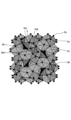
- FIG. 3 is a cross-sectional view of active material 19 and solid electrolyte particles 20 appearing in region 18 of active material layer 13 of positive electrode 11.
- the cross section of active material layer 13 is a polished surface, a surface obtained by irradiating with a focused ion beam (FIB), or a surface obtained by ion milling.
- FIB focused ion beam
- Examples of ion milling conditions include an acceleration voltage of 4.0 kV, an environmental temperature of -80°C, a processing time of 8 hours, and a degree of vacuum of 10-3 Pa or less.
- the polished surface is, for example, a surface that is polished after freezing the active material layer 13 or embedding and solidifying the active material layer 13 in a tetrafunctional epoxy resin or the like.
- the active material 19 and particles 20 that appear in the cross section are analyzed using a scanning electron microscope (SEM) equipped with an energy dispersive X-ray spectrometer (EDS) to identify the element distribution and the contrast of the reflected electron image through image analysis.
- SEM scanning electron microscope
- EDS energy dispersive X-ray spectrometer
- the ratio of the active material 19 in the active material layer 13 is preferably 70 vol% or more and 99.9 vol% or less. This is to ensure the capacity of the power storage device 10.
- the ratio of the cross-sectional area of the active material 19 to a square area (area 2500 ⁇ m 2 ) with one side of 50 ⁇ m on the cross section of the active material layer 13 is regarded as the ratio (vol%) of the active material 19.
- the thickness of the active material layer 13 is less than 50 ⁇ m, it is not possible to set a square area of 2500 ⁇ m 2 , so a rectangular area (area 2500 ⁇ m 2 ) consisting of two short sides extending in the thickness direction (the length of the short sides corresponds to the thickness of the active material layer 13) and two long sides perpendicular to the short sides is set, and the ratio of the active material 19 therein is determined.
- the average circle-equivalent diameter of the active material 19 appearing on the cross section of the active material layer 13 is preferably 5 ⁇ m or more. This is to prevent the interface of the active material 19 from expanding, which is one of the causes of an increase in charge transfer resistance.
- the circle-equivalent diameter of the active material 19 is the diameter of a circle having an area equal to the area of the cross section of the active material 19 obtained by image analysis.
- the circle-equivalent diameters of the active material 19 appearing on the cross section of the active material layer 13 within an area of 2500 ⁇ m2 are obtained, and the sum of the circle-equivalent diameters obtained is divided by the total number of active materials 19 to obtain the average.
- the average circle-equivalent diameter of the active material 19 appearing on the cross section of the active material layer 13 is preferably 15 ⁇ m or less. This is to ensure the packing density of the active material 19.
- the proportion of particles 20 in active material layer 13 is preferably 0.1 vol % or more and 30 vol % or less in order to ensure the capacity of electricity storage device 10 and to ensure reaction sites between active material 19 and particles 20.
- the proportion of the cross-sectional area of particles 20 in a range of 2500 ⁇ m2 on the cross section of active material layer 13 is regarded as the proportion (vol %) of particles 20.
- the average circle-equivalent diameter of the particles 20 appearing on the cross section of the active material layer 13 is preferably 10 ⁇ m or less, more preferably 5 ⁇ m or less. This is to ensure the number of reaction sites between the active material 19 and the particles 20.
- the circle-equivalent diameter of the particles 20 is the diameter of a circle having an area equal to the area of the cross section of the particles 20 obtained by image analysis.
- the circle-equivalent diameters of the particles 20 appearing on the cross section of the active material layer 13 within an area of 2500 ⁇ m2 are obtained, and the sum of the circle-equivalent diameters obtained is divided by the total number of the particles 20 to obtain the average.
- the average circle-equivalent diameter of the particles 20 appearing on the cross section of the active material layer 13 is preferably 0.5 ⁇ m or more. This is to facilitate the handling of the particles 20.
- the active material layer 13 may contain a binder that binds the active material 19, and a conductive additive that reduces the electron transfer resistance of the active material layer 13.
- conductive additives include carbon black, acetylene black, ketjen black, carbon fiber, Ni, Pt, and Ag.
- binder there are no particular limitations on the binder as long as it binds the active material 19.
- binders include fluorinated resins, polyolefins, polyimides, polyvinylpyrrolidone, polyvinyl alcohol, cellulose ether, styrene butadiene rubber, and other rubber-like polymers.
- fluorinated resins examples include vinylidene fluoride polymers, polychlorotrifluoroethylene, polyvinyl fluoride, tetrafluoroethylene-perfluoroalkyl vinyl ether copolymers, tetrafluoroethylene-hexafluoropropylene copolymers, ethylene-tetrafluoroethylene copolymers, and ethylene-chlorotrifluoroethylene copolymers.
- the area 18 is a square section with a side length of 20 ⁇ m, in which six or more particles 20 appear in an area of 400 ⁇ m2 on the cross section of the active material layer 13.
- the particles 20 are detected by image analysis.
- the image is composed of 160,000 pixels obtained by dividing one side of the square section by 400.
- particles 20 are defined as those with a size of four pixels or more.
- FIG. 4 is a cross-sectional view of particles 20 appearing in a region 18 of the active material layer 13. Below, an example of a region 18 in which seven particles 20 appear will be described. Region 18 is an area for calculating the average distance D between particles 20. The reason that a region in which six or more particles 20 appear is designated as region 18 is to ensure the accuracy of the calculated average distance D.
- the distance D between the particles 20 is the length of a line segment connecting the centers of gravity 21 of the cross sections of the particles 20.
- the center of gravity 21 is the geometric center when the cross section of the particle 20 is a planar figure.
- the average of the distances D is 1.0 ⁇ m or more. This allows the particles 20 to be dispersed in the active material layer 13. Since the particles 20 contribute to the movement of charge carriers, the number of reaction sites can be increased by the particles 20 dispersed in the active material layer 13. Therefore, the charge transfer resistance in the positive electrode 11 can be reduced.
- the average of the distance D is moderately large. This is because the particles 20 are dispersed over a wide range within the active material layer 13.
- the average of the distance D is preferably 2.0 ⁇ m or more, more preferably 3.0 ⁇ m or more, even more preferably 5.0 ⁇ m or more, and even more preferably 10.0 ⁇ m or more.
- the average distance D between particles 20 in any 10 areas 18 on the cross section of the active material layer 13 is 1.0 ⁇ m or more. This is because the dispersibility of the particles 20 in the active material layer 13 can be further improved.
- Li2CO3 , MgO, La(OH) 3 , SrCO3 , and ZrO2 were weighed to obtain Li6.95Mg0.15La2.75Sr0.25Zr2.0O12 .
- Li2CO3 was weighed out at about 15 mol % excess in terms of element, taking into account the volatilization of Li during firing.
- the weighed raw materials and ethanol were put into a nylon pot together with zirconia balls, and were ground and mixed in a ball mill for 15 hours.
- the slurry taken out of the pot was dried, and then fired on a MgO plate at 1100°C for 15 hours.
- the fired powder was ground, placed in a MgO sheath, and further fired at 1100°C for 4 hours.
- the fired powder was pulverized in a glove box under an argon atmosphere to obtain various oxide solid electrolytes (hereinafter referred to as "LLZ") with different particle sizes.
- LLZ oxide solid electrolytes
- the crystal structure of LLZ was confirmed to be a garnet type by powder X-ray diffraction.
- test The cell was subjected to constant current-constant voltage charge and discharge at 25° C.
- the charging was performed by constant current charging at 0.2 C until the terminal voltage reached 4.2 V, followed by constant voltage charging until the current value reached 0.01 C.
- the discharging was performed by constant voltage discharging at 0.2 C until the terminal voltage reached 2.5 V, followed by constant voltage discharging until the current value reached 0.01 C.
- the charge transfer resistance of the cell at 20° C. after charging and discharging was measured by an AC impedance method (frequency 1 MHz-100 mHz).
- the charge transfer resistance of the cell with an average interparticle distance D of 0.60 ⁇ m was 6% higher than the charge transfer resistance of the comparative cell that did not contain particles. This cell showed abnormalities such as two-stage discharge during discharge.
- the charge transfer resistance of cells in which the average interparticle distance D was 1.00 ⁇ m or more was reduced compared to the charge transfer resistance of cells in the comparative example that did not contain particles. Specifically, the charge transfer resistance of cells in which the average distance D was 1.00 ⁇ m was reduced by 5%, the charge transfer resistance of cells in which the average distance D was 1.10 ⁇ m was reduced by 15%, and the charge transfer resistance of cells in which the average distance D was 1.86 ⁇ m was reduced by 22%. It was found that the charge transfer resistance decreased as the average distance D increased.
- the overvoltage caused by the resistance component of the positive electrode is reduced, and the input/output characteristics of the electricity storage device are expected to improve. Furthermore, since the non-uniformity of the reaction sites of the charge carriers is reduced, the utilization rate of the active material is improved, and the discharge capacity of the electricity storage device is expected to increase.
- the electricity storage device 10 is described as having a positive electrode 11 in which an active material layer 13 is provided on one side of a current collector 12, and a negative electrode 15 in which an active material layer 17 is provided on one side of a current collector 16, but this is not necessarily limited to this.
- an electricity storage device having an electrode layer (so-called bipolar electrode) in which an active material layer 13 and an active material layer 17 are provided on both sides of a current collector 12. If bipolar electrodes and separators 14 are alternately stacked and housed in a case (not shown), an electricity storage device with a so-called bipolar structure is obtained.
- Electricity storage device 11 Positive electrode (electrode) 18 Area 19 Active material 20 Particle D Distance between particles
Landscapes
- Chemical & Material Sciences (AREA)
- Chemical Kinetics & Catalysis (AREA)
- Electrochemistry (AREA)
- General Chemical & Material Sciences (AREA)
- Engineering & Computer Science (AREA)
- Manufacturing & Machinery (AREA)
- Materials Engineering (AREA)
- Physics & Mathematics (AREA)
- Condensed Matter Physics & Semiconductors (AREA)
- General Physics & Mathematics (AREA)
- Inorganic Chemistry (AREA)
- Secondary Cells (AREA)
Priority Applications (3)
| Application Number | Priority Date | Filing Date | Title |
|---|---|---|---|
| KR1020257032058A KR20250168236A (ko) | 2023-08-31 | 2024-08-27 | 전극 및 축전 디바이스 |
| CN202480021831.9A CN120937143A (zh) | 2023-08-31 | 2024-08-27 | 电极和蓄电装置 |
| JP2025543507A JPWO2025047738A1 (https=) | 2023-08-31 | 2024-08-27 |
Applications Claiming Priority (2)
| Application Number | Priority Date | Filing Date | Title |
|---|---|---|---|
| JP2023-140944 | 2023-08-31 | ||
| JP2023140944 | 2023-08-31 |
Publications (1)
| Publication Number | Publication Date |
|---|---|
| WO2025047738A1 true WO2025047738A1 (ja) | 2025-03-06 |
Family
ID=94819223
Family Applications (1)
| Application Number | Title | Priority Date | Filing Date |
|---|---|---|---|
| PCT/JP2024/030499 Pending WO2025047738A1 (ja) | 2023-08-31 | 2024-08-27 | 電極および蓄電デバイス |
Country Status (4)
| Country | Link |
|---|---|
| JP (1) | JPWO2025047738A1 (https=) |
| KR (1) | KR20250168236A (https=) |
| CN (1) | CN120937143A (https=) |
| WO (1) | WO2025047738A1 (https=) |
Citations (6)
| Publication number | Priority date | Publication date | Assignee | Title |
|---|---|---|---|---|
| JP2013196968A (ja) * | 2012-03-21 | 2013-09-30 | Toyota Motor Corp | 正極活物質層含有体の製造方法 |
| KR20200020649A (ko) * | 2018-08-17 | 2020-02-26 | 주식회사 엘지화학 | 전기화학소자용 전극을 제조하는 방법 |
| WO2021033424A1 (ja) * | 2019-08-22 | 2021-02-25 | 日本特殊陶業株式会社 | 蓄電デバイス用電極および蓄電デバイス |
| WO2021181529A1 (ja) * | 2020-03-10 | 2021-09-16 | 本田技研工業株式会社 | リチウムイオン二次電池用電極、およびリチウムイオン二次電池 |
| WO2022196364A1 (ja) * | 2021-03-18 | 2022-09-22 | パナソニックIpマネジメント株式会社 | 全固体電池およびその製造方法 |
| WO2023149426A1 (ja) * | 2022-02-02 | 2023-08-10 | 日本特殊陶業株式会社 | リチウムイオン伝導体、シート及び蓄電デバイス |
Family Cites Families (1)
| Publication number | Priority date | Publication date | Assignee | Title |
|---|---|---|---|---|
| WO2018198494A1 (ja) | 2017-04-28 | 2018-11-01 | 株式会社 オハラ | 全固体電池 |
-
2024
- 2024-08-27 JP JP2025543507A patent/JPWO2025047738A1/ja active Pending
- 2024-08-27 CN CN202480021831.9A patent/CN120937143A/zh active Pending
- 2024-08-27 KR KR1020257032058A patent/KR20250168236A/ko active Pending
- 2024-08-27 WO PCT/JP2024/030499 patent/WO2025047738A1/ja active Pending
Patent Citations (6)
| Publication number | Priority date | Publication date | Assignee | Title |
|---|---|---|---|---|
| JP2013196968A (ja) * | 2012-03-21 | 2013-09-30 | Toyota Motor Corp | 正極活物質層含有体の製造方法 |
| KR20200020649A (ko) * | 2018-08-17 | 2020-02-26 | 주식회사 엘지화학 | 전기화학소자용 전극을 제조하는 방법 |
| WO2021033424A1 (ja) * | 2019-08-22 | 2021-02-25 | 日本特殊陶業株式会社 | 蓄電デバイス用電極および蓄電デバイス |
| WO2021181529A1 (ja) * | 2020-03-10 | 2021-09-16 | 本田技研工業株式会社 | リチウムイオン二次電池用電極、およびリチウムイオン二次電池 |
| WO2022196364A1 (ja) * | 2021-03-18 | 2022-09-22 | パナソニックIpマネジメント株式会社 | 全固体電池およびその製造方法 |
| WO2023149426A1 (ja) * | 2022-02-02 | 2023-08-10 | 日本特殊陶業株式会社 | リチウムイオン伝導体、シート及び蓄電デバイス |
Also Published As
| Publication number | Publication date |
|---|---|
| CN120937143A (zh) | 2025-11-11 |
| KR20250168236A (ko) | 2025-12-02 |
| JPWO2025047738A1 (https=) | 2025-03-06 |
Similar Documents
| Publication | Publication Date | Title |
|---|---|---|
| EP3930051B1 (en) | Positive electrode material and application thereof | |
| CN115036565B (zh) | 固体电解质材料和电池 | |
| CN100438144C (zh) | 二次电池用正极活性材料,二次电池用正极,二次电池及制备二次电池用正极活性材料的方法 | |
| US20070111097A1 (en) | Lithium-cobalt composite oxide, process for its production, positive electrode for lithium secondary cell employing it, and lithium secondary cell | |
| US11777132B2 (en) | Solid electrolyte material and battery | |
| WO2019039566A1 (ja) | 非水系電解質二次電池用正極活物質とその製造方法、及び、非水系電解質二次電池とその製造方法 | |
| JP7819217B2 (ja) | リチウムイオン伝導体、シート及び蓄電デバイス | |
| JP7769981B2 (ja) | 固体電解質材料およびそれを用いた電池 | |
| JP7724437B2 (ja) | 固体電解質材料およびそれを用いた電池 | |
| JP7731077B2 (ja) | 固体電解質材料およびそれを用いた電池 | |
| JP7731058B2 (ja) | 固体電解質材料およびそれを用いた電池 | |
| WO2022215337A1 (ja) | 固体電解質材料およびそれを用いた電池 | |
| WO2025047738A1 (ja) | 電極および蓄電デバイス | |
| JP2024125456A (ja) | 二次電池およびその製造方法 | |
| JP7820616B2 (ja) | 電解液、電解質組成物および電気化学素子 | |
| WO2025182453A1 (ja) | 非水電解液および電気化学素子 | |
| WO2025047736A1 (ja) | 電解液、電解質組成物および電気化学素子 | |
| WO2025182454A1 (ja) | 電極用組成物、電極および電気化学素子 | |
| JP2025132319A (ja) | 固体電解質の製造方法、セパレータの製造方法、電極の製造方法および蓄電デバイスの製造方法 | |
| JP2025132324A (ja) | 固体電解質の製造方法、セパレータの製造方法、電極の製造方法および蓄電デバイスの製造方法 | |
| WO2025183000A1 (ja) | 電極および蓄電デバイス | |
| JP2025132328A (ja) | 固体電解質、イオン伝導体、シート及び蓄電デバイス | |
| JP2025132313A (ja) | 固体電解質、イオン伝導体、シート及び蓄電デバイス | |
| WO2025225308A1 (ja) | 固体電解質材料、正極材料、電池、及び固体電解質材料の製造方法 | |
| JP2026042442A (ja) | 粉末、シート及び二次電池 |
Legal Events
| Date | Code | Title | Description |
|---|---|---|---|
| 121 | Ep: the epo has been informed by wipo that ep was designated in this application |
Ref document number: 24859770 Country of ref document: EP Kind code of ref document: A1 |
|
| ENP | Entry into the national phase |
Ref document number: 2025543507 Country of ref document: JP Kind code of ref document: A |
|
| WWE | Wipo information: entry into national phase |
Ref document number: 2025543507 Country of ref document: JP |
|
| ENP | Entry into the national phase |
Ref document number: 1020257032058 Country of ref document: KR Free format text: ST27 STATUS EVENT CODE: A-0-1-A10-A15-NAP-PA0105 (AS PROVIDED BY THE NATIONAL OFFICE) |
|
| WWE | Wipo information: entry into national phase |
Ref document number: KR1020257032058 Country of ref document: KR |
|
| WWE | Wipo information: entry into national phase |
Ref document number: CN2024800218319 Country of ref document: CN |
|
| WWE | Wipo information: entry into national phase |
Ref document number: 2024859770 Country of ref document: EP |