WO2025041629A1 - 基板処理装置及び搬送方法 - Google Patents
基板処理装置及び搬送方法 Download PDFInfo
- Publication number
- WO2025041629A1 WO2025041629A1 PCT/JP2024/028409 JP2024028409W WO2025041629A1 WO 2025041629 A1 WO2025041629 A1 WO 2025041629A1 JP 2024028409 W JP2024028409 W JP 2024028409W WO 2025041629 A1 WO2025041629 A1 WO 2025041629A1
- Authority
- WO
- WIPO (PCT)
- Prior art keywords
- cassette
- substrate processing
- processing apparatus
- transport
- substrate
- Prior art date
- Legal status (The legal status is an assumption and is not a legal conclusion. Google has not performed a legal analysis and makes no representation as to the accuracy of the status listed.)
- Pending
Links
Images




Classifications
-
- H—ELECTRICITY
- H10—SEMICONDUCTOR DEVICES; ELECTRIC SOLID-STATE DEVICES NOT OTHERWISE PROVIDED FOR
- H10P—GENERIC PROCESSES OR APPARATUS FOR THE MANUFACTURE OR TREATMENT OF DEVICES COVERED BY CLASS H10
- H10P72/00—Handling or holding of wafers, substrates or devices during manufacture or treatment thereof
- H10P72/30—Handling or holding of wafers, substrates or devices during manufacture or treatment thereof for conveying, e.g. between different workstations
- H10P72/32—Handling or holding of wafers, substrates or devices during manufacture or treatment thereof for conveying, e.g. between different workstations between different workstations
- H10P72/3218—Conveying cassettes, containers or carriers
-
- B—PERFORMING OPERATIONS; TRANSPORTING
- B65—CONVEYING; PACKING; STORING; HANDLING THIN OR FILAMENTARY MATERIAL
- B65G—TRANSPORT OR STORAGE DEVICES, e.g. CONVEYORS FOR LOADING OR TIPPING, SHOP CONVEYOR SYSTEMS OR PNEUMATIC TUBE CONVEYORS
- B65G49/00—Conveying systems characterised by their application for specified purposes not otherwise provided for
- B65G49/05—Conveying systems characterised by their application for specified purposes not otherwise provided for for fragile or damageable materials or articles
- B65G49/07—Conveying systems characterised by their application for specified purposes not otherwise provided for for fragile or damageable materials or articles for semiconductor wafers Not used, see H10P72/00
-
- B—PERFORMING OPERATIONS; TRANSPORTING
- B65—CONVEYING; PACKING; STORING; HANDLING THIN OR FILAMENTARY MATERIAL
- B65G—TRANSPORT OR STORAGE DEVICES, e.g. CONVEYORS FOR LOADING OR TIPPING, SHOP CONVEYOR SYSTEMS OR PNEUMATIC TUBE CONVEYORS
- B65G54/00—Non-mechanical conveyors not otherwise provided for
- B65G54/02—Non-mechanical conveyors not otherwise provided for electrostatic, electric, or magnetic
-
- H—ELECTRICITY
- H10—SEMICONDUCTOR DEVICES; ELECTRIC SOLID-STATE DEVICES NOT OTHERWISE PROVIDED FOR
- H10P—GENERIC PROCESSES OR APPARATUS FOR THE MANUFACTURE OR TREATMENT OF DEVICES COVERED BY CLASS H10
- H10P72/00—Handling or holding of wafers, substrates or devices during manufacture or treatment thereof
- H10P72/04—Apparatus for manufacture or treatment
- H10P72/0451—Apparatus for manufacturing or treating in a plurality of work-stations
- H10P72/0464—Apparatus for manufacturing or treating in a plurality of work-stations characterised by the construction of the transfer chamber
-
- H—ELECTRICITY
- H10—SEMICONDUCTOR DEVICES; ELECTRIC SOLID-STATE DEVICES NOT OTHERWISE PROVIDED FOR
- H10P—GENERIC PROCESSES OR APPARATUS FOR THE MANUFACTURE OR TREATMENT OF DEVICES COVERED BY CLASS H10
- H10P72/00—Handling or holding of wafers, substrates or devices during manufacture or treatment thereof
- H10P72/30—Handling or holding of wafers, substrates or devices during manufacture or treatment thereof for conveying, e.g. between different workstations
-
- H—ELECTRICITY
- H10—SEMICONDUCTOR DEVICES; ELECTRIC SOLID-STATE DEVICES NOT OTHERWISE PROVIDED FOR
- H10P—GENERIC PROCESSES OR APPARATUS FOR THE MANUFACTURE OR TREATMENT OF DEVICES COVERED BY CLASS H10
- H10P72/00—Handling or holding of wafers, substrates or devices during manufacture or treatment thereof
- H10P72/30—Handling or holding of wafers, substrates or devices during manufacture or treatment thereof for conveying, e.g. between different workstations
- H10P72/33—Handling or holding of wafers, substrates or devices during manufacture or treatment thereof for conveying, e.g. between different workstations into and out of processing chamber
- H10P72/3311—Horizontal transfer of a batch of workpieces
-
- H—ELECTRICITY
- H10—SEMICONDUCTOR DEVICES; ELECTRIC SOLID-STATE DEVICES NOT OTHERWISE PROVIDED FOR
- H10P—GENERIC PROCESSES OR APPARATUS FOR THE MANUFACTURE OR TREATMENT OF DEVICES COVERED BY CLASS H10
- H10P72/00—Handling or holding of wafers, substrates or devices during manufacture or treatment thereof
- H10P72/30—Handling or holding of wafers, substrates or devices during manufacture or treatment thereof for conveying, e.g. between different workstations
- H10P72/33—Handling or holding of wafers, substrates or devices during manufacture or treatment thereof for conveying, e.g. between different workstations into and out of processing chamber
- H10P72/3312—Vertical transfer of a batch of workpieces
-
- B—PERFORMING OPERATIONS; TRANSPORTING
- B65—CONVEYING; PACKING; STORING; HANDLING THIN OR FILAMENTARY MATERIAL
- B65G—TRANSPORT OR STORAGE DEVICES, e.g. CONVEYORS FOR LOADING OR TIPPING, SHOP CONVEYOR SYSTEMS OR PNEUMATIC TUBE CONVEYORS
- B65G2201/00—Indexing codes relating to handling devices, e.g. conveyors, characterised by the type of product or load being conveyed or handled
- B65G2201/02—Articles
- B65G2201/0297—Wafer cassette
Definitions
- This disclosure relates to a substrate processing apparatus and a transport method.
- Patent Document 1 discloses a substrate processing apparatus that removes and processes substrates from a carrier for storing and transporting multiple substrates.
- the carrier is transported to a load port where the carrier is loaded and unloaded using a ceiling transport device that moves along a track formed in the ceiling of the clean room in which the substrate processing apparatus is installed.
- the technology disclosed herein improves the efficiency of transporting cassettes to substrate processing equipment.
- One aspect of the present disclosure is a substrate processing apparatus that processes substrates stored in a cassette and transported, and includes at least one transport block that transports the substrates internally, a substrate processing module that processes the substrates, and a cassette transport mechanism that is configured to transport the cassette between a transfer position set on the outer surface of the substrate processing apparatus and a load/unload position into the substrate processing apparatus, the cassette transport mechanism including a placement section for placing the cassette, and a movement mechanism that moves the cassette placed on the placement section.
- the present disclosure improves the efficiency of transporting cassettes to substrate processing equipment.
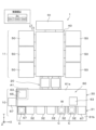
- FIG. 1 is a plan view diagrammatically illustrating an example of the configuration of a substrate processing apparatus according to an embodiment of the present invention
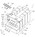
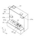
- 1 is a perspective view showing a configuration example of a substrate processing apparatus according to an embodiment of the present invention
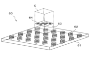
- 1 is a perspective view showing a schematic configuration example of a cassette transport mechanism that moves on a horizontal plane
- 1 is a perspective view showing a schematic configuration example of a cassette transport mechanism that moves on a vertical plane
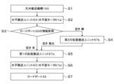
- FIG. 11 is a flow diagram showing a flow of transport of a cassette.
- 11 is an explanatory view showing a retreat position of a cassette in the substrate processing apparatus
- FIG. 11 is an explanatory view showing a retreat position of a cassette in the substrate processing apparatus
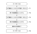
- FIG. 11 is a flow diagram showing a flow of transport of a cassette.
- FIG. 11 is a flow diagram showing a flow of transport of a cassette.
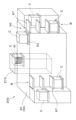
- FIG. 13 is a perspective view showing another configuration example of the substrate processing apparatus.
- FIG. 13 is a perspective view showing another configuration example of the substrate processing apparatus.
- OHT Overhead Hoist Transport
- the placement of the load port of the substrate processing device is limited to the movable range of the ceiling transport device, in other words, directly below the rails, reducing the degree of freedom in placement of the substrate processing device. Also, when unloading a cassette from the substrate processing device, it is necessary to wait for the arrival of the ceiling transport device in order to transport the cassette C, which can result in reduced throughput.
- Figures 1 and 2 are a plan view and a perspective view, respectively, showing an outline of the configuration of a substrate processing apparatus 1 according to the present embodiment. Note that a wafer is an example of a substrate.
- the substrate processing apparatus 1 has a configuration in which an atmospheric section 10 and a reduced pressure section 11 are integrally connected via a load lock module 20.
- the atmospheric section 10 includes an atmospheric module that processes and/or transports a substrate W in an atmospheric atmosphere.
- the reduced pressure section 11 includes a reduced pressure module (vacuum module) that processes and/or transports a substrate W in a reduced pressure (vacuum) atmosphere.
- the load lock module 20 has an internal load lock chamber (not shown) configured to temporarily hold the substrate W.
- the load lock chamber is provided to communicate with the internal space of the atmospheric section 10 and the internal space of the reduced pressure section 11 via a substrate transfer port (not shown).
- the load lock chamber is also configured so that its interior can be switched between atmospheric atmosphere and reduced pressure atmosphere (vacuum state).
- the load lock module 20 is configured so that the substrate W can be appropriately transferred between the atmospheric section 10, which has an atmospheric atmosphere, and the reduced pressure section 11, which has a reduced pressure atmosphere.
- the atmospheric section 10 has an atmospheric transport block 30 and a loading/unloading block 31.
- the loading/unloading block 31 is constructed one step lower than the atmospheric transport block 30, and multiple, for example five, load ports 32 are provided on the upper surface of the loading/unloading block 31.
- the load ports 32 serve as positions for loading and unloading substrates W into and from the substrate processing apparatus 1, and each of the load ports 32 can accommodate a cassette C containing multiple substrates W (for example, one lot of 25 substrates).
- the atmospheric transfer block 30 is made up of a rectangular housing, and the interior of the housing is maintained at atmospheric atmosphere.
- a substrate transfer mechanism (not shown) is arranged inside the atmospheric transfer block 30.
- a plurality of substrate transfer ports 33 are formed on one side constituting the long side of the atmospheric transfer block 30 in the negative Y-axis direction, and the above-mentioned load ports 32 are arranged in a line corresponding to each of these substrate transfer ports 33.
- a load lock module 20 is arranged on the other side constituting the long side of the atmospheric transfer block 30 in the positive Y-axis direction.
- the decompression section 11 has a vacuum transfer block 40 and a substrate processing module 50.
- the interiors of the vacuum transfer block 40 and the substrate processing module 50 are each configured to be able to maintain a decompressed (vacuum) atmosphere.
- multiple substrate processing modules 50 for example seven, are connected to one vacuum transfer block 40.
- the number and arrangement of the substrate processing modules 50 are not limited to this embodiment and can be set as desired.
- the vacuum transport block 40 is made up of a rectangular housing.
- a substrate transport mechanism (not shown) is arranged inside the vacuum transport block 40.
- a plurality of substrate transport ports (not shown), for example three each, are formed on the side surfaces constituting the long sides of the vacuum transport block 40 in the positive and negative directions of the X-axis, and a substrate processing module 50 is connected to each of these substrate transport ports.
- a substrate transport port (not shown) is also formed on one side surface constituting the short side of the vacuum transport block 40 in the positive direction of the Y-axis, and a substrate processing module 50 is connected to the substrate transport port.
- a load lock module 20 is arranged on the other side surface constituting the short side of the vacuum transport block 40 in the negative direction of the Y-axis.
- the substrate processing module 50 performs the desired processing on the substrate W transported from the vacuum transport block 40.
- the type and configuration of the substrate processing module 50 are not particularly limited, and it can have any configuration, such as a coating and developing module or a plasma processing module.
- the substrate processing apparatus 1 is provided with a cassette transport mechanism 60 for transporting the cassette C delivered from the ceiling transport mechanism 100 (described later) to the load port 32.
- the cassette transport mechanism 60 has a horizontal plane motor 61, a horizontal transport unit 63, a vertical plane motor 65, and a vertical transport unit 67.
- the horizontal plane motor 61 includes a first horizontal plane motor 61a on the atmospheric transport block 30 and a second horizontal plane motor 61b on the load/unload block 31, which are arranged so as to cover the upper surfaces of the atmospheric transport block 30 and the load/unload block 31, respectively. Since the first horizontal plane motor 61a and the second horizontal plane motor 61b have the same configuration, in the following description, they may be collectively referred to simply as the "horizontal plane motor 61.”
- multiple coils 62 (first coils) are arranged inside the horizontal motor 61.
- the coils 62 generate a magnetic field when supplied with current from a power source (not shown). It is desirable that the power supplied to each of the multiple coils 62 be configured so that it can be independently controlled, for example, under the control unit 2 described below.
- a transfer position A1 is set at the end on the negative X-axis side and the positive Y-axis side on the atmospheric transport block 30 for transferring cassettes C between the ceiling transport mechanism 100, which will be described later. Therefore, at least the set position of transfer position A1 on the atmospheric transport block 30 is located directly below the rail R for transporting the ceiling transport mechanism 100, which will be described later.
- the horizontal conveying unit 63 is formed of a column (hence, a rectangular column in the illustrated example) having, for example, the same cross-sectional shape as the cassette C in plan view.
- the cassette C is placed on the upper surface of the horizontal conveying unit 63. Therefore, the horizontal conveying unit 63 constitutes a "placement section" according to the technology of the present disclosure.
- a plurality of permanent magnets 64 are arranged in the horizontal conveying unit 63.
- the horizontal conveying unit 63 is magnetically levitated above the horizontal plane motor 61 by the magnetic field generated by the coil 62. The amount of levitation of the horizontal conveying unit 63 relative to the horizontal plane motor 61 can be controlled by the magnitude of the current supplied to the coil 62.
- the horizontal conveying unit 63 moves and rotates on the horizontal plane motor 61 by the magnetic field generated by the coil 62. Therefore, in this embodiment, the horizontal plane motor 61 and the horizontal conveying unit 63 may be collectively referred to as a "moving mechanism" according to the technology of the present disclosure.
- the vertical motor 65 is provided at desired positions on the side of the atmospheric transport block 30, in the illustrated example, on the side on the negative Y-axis direction to which the load/unload block 31 is connected, and on the side on the negative X-axis direction.
- multiple coils 66 (second coils) are arranged inside the vertical motor 65.
- the coils 66 generate a magnetic field when supplied with current from a power source (not shown). It is desirable that the power supplied to each of the multiple coils 66 be configured to be independently controllable, for example under the control of the control unit 2 described below.
- the vertical transport unit 67 includes a first vertical transport unit 67a arranged on the side of the atmospheric transport block 30 facing the negative Y-axis direction, and a second vertical transport unit 67b arranged on the side of the atmospheric transport block 30 facing the negative X-axis direction. Since the first vertical transport unit 67a and the second vertical transport unit 67b have a similar configuration, in the following description, they may be collectively referred to simply as the "vertical transport unit 67.”
- the vertical transport unit 67 has a mounting portion 68 that has a cross-sectional shape that is approximately the same as that of a cassette C when viewed in a plane, and a moving portion 69 that is suspended from the end of the mounting portion 68 so as to face the vertical motor 65.
- a cassette C is placed on the top surface of the placement portion 68.
- a plurality of coils 68a are also arranged on the placement portion 68.
- the horizontal transport unit 63 is magnetically levitated above the placement portion 68 by the magnetic field generated by the coils 68a.
- the substrate processing apparatus 1 is configured to be able to transfer the horizontal transport unit 63 between the horizontal plane motor 61 and the placement portion 68 under the control of the control unit 2, which will be described later.
- the amount of levitation of the horizontal transport unit 63 relative to the placement portion 68 can be controlled by the magnitude of the current supplied to the coils 68a.
- the horizontal transport unit 63 moves and rotates on the placement portion 68 by the magnetic field generated by the coils 68a.
- the moving part 69 is composed of a surface facing the vertical motor 65. A number of permanent magnets 69a are arranged in the moving part 69.
- the moving part 69 is magnetically levitated along the surface direction of the vertical motor 65 by the magnetic field generated by the coil 66 of the vertical motor 65. Therefore, the moving part 69 moves along the vertical motor 65 by the magnetic field generated by the vertical transport unit 67 and the coil 66.
- the first vertical transport unit 67a controls the power supplied to each of the coils 62, 66, and 68a under the control of the control unit 2, and the horizontal transport unit 63 carrying the cassette C is configured to be freely moved between the atmospheric transport block 30 and the load/unload block 31.
- the second vertical transport unit 67b is configured to control the power supplied to each of the coils 62, 66, 68a under the control of the control unit 2, and to temporarily hold the cassette C on the side of the atmospheric transport block 30 so as to be able to wait. Therefore, the second vertical transport unit 67b has a configuration as a buffer mechanism for the cassette C.
- the cassette transport mechanism 60 transports the cassette C transported from the ceiling transport mechanism 100 between the transfer position A1 and the load port 32 (the position where the substrate W is loaded and unloaded).
- the substrate processing apparatus 1 is provided with a control unit 2 as shown in FIG. 1.
- the control unit 2 processes computer-executable instructions that cause the substrate processing apparatus 1 to perform the various steps described in this disclosure.
- the control unit 2 may be configured to control each element of the substrate processing apparatus 1 to perform the various steps described herein. In one embodiment, a part or all of the control unit 2 may be included in the substrate processing apparatus 1.
- the control unit 2 may include a processing unit 2a1, a storage unit 2a2, and a communication interface 2a3.
- the control unit 2 is realized, for example, by a computer 2a.
- the processing unit 2a1 may be configured to perform various control operations by reading a program from the storage unit 2a2 and executing the read program.
- This program may be stored in the storage unit 2a2 in advance, or may be acquired via a medium when necessary.
- the acquired program is stored in the storage unit 2a2, and is read from the storage unit 2a2 by the processing unit 2a1 and executed.
- the medium may be various storage media readable by the computer 2a, or may be a communication line connected to the communication interface 2a3.
- the processing unit 2a1 may be a CPU (Central Processing Unit).
- the storage unit 2a2 may include a RAM (Random Access Memory), a ROM (Read Only Memory), a HDD (Hard Disk Drive), an SSD (Solid State Drive), or a combination of these.
- the communication interface 2a3 may communicate with the substrate processing apparatus 1 via a communication line such as a LAN (Local Area Network).
- the above storage medium may be temporary or non-temporary.
- a ceiling transport mechanism 100 is provided that can move freely along rails R provided on the ceiling surface of the clean room in which the substrate processing apparatus 1 is placed.
- the ceiling transport mechanism 100 can transport cassettes C between the substrate processing apparatus 1 and other substrate processing apparatus 1 provided outside the substrate processing apparatus 1, and can access the transfer position A1 set on the ceiling surface of the atmospheric transfer block 30 from above to transfer the cassettes C.
- Fig. 5 is a flow chart showing a flow of transport of the cassette C storing unprocessed substrates W.
- the ceiling transport mechanism 100 holding a cassette (hereinafter, for convenience, the cassette to be transported is referred to as "cassette C1") containing multiple unprocessed substrates W moves above the transfer position A1 set on the first horizontal motor 61a of the substrate processing apparatus 1 (step S1 in FIG. 5).
- a horizontal transport unit 63 not carrying another cassette (hereinafter, for convenience, referred to as “another cassette C2”) is waiting in advance, and the cassette C1 is directly transferred from the ceiling transport mechanism 100 to the horizontal transport unit 63 (step S2 in FIG. 5).
- the supply of current to the coil 62 of the first horizontal motor 61a is then started to magnetically levitate the horizontal transport unit 63, and the horizontal transport unit 63 starts to move horizontally.
- the placement status of other cassettes C2 in the load port 32 of the loading/unloading block 31, in other words, the availability information of the load port 32 is obtained (step S3 in FIG. 5).
- the horizontal transport unit 63 with the cassette C1 placed on it is moved to the placement portion 68 of the second vertical transport unit 67b (step S4 in FIG. 5).
- the supply of current to the coil 68a of the placement portion 68 may be started in advance prior to the transfer of the cassette C1 to the placement portion 68, or may be started simultaneously with the transfer of the cassette C1 to the placement portion 68.
- the cassette C1 (horizontal transport unit 63) that has been transferred to the placement portion 68 is then moved along the vertical plane motor 65 by the supply of current to the coil 66, and temporarily waits at the desired standby position until a vacant load port 32 becomes available.
- step S3 If the load port 32 is empty in step S3, or if the load port 32 becomes empty after a temporary wait at the second vertical transport unit 67b, the horizontal transport unit 63 with the cassette C1 placed thereon is moved to the placement portion 68 of the first vertical transport unit 67a (step S5 in FIG. 5). At this time, the supply of current to the coil 68a of the placement portion 68 may be started in advance of the transfer of the cassette C1 to the placement portion 68, or may be started simultaneously with the transfer of the cassette C1 to the placement portion 68.
- the cassette C1 (horizontal transport unit 63) that has been transferred to the placement portion 68 is then lowered to the height position of the loading/unloading block 31 by the first vertical transport unit 67a moving along the vertical plane motor 65 due to the supply of current to the coil 66.
- the horizontal transport unit 63 carrying the cassette C1 is moved to the second horizontal motor 61b (step S6 in FIG. 5).
- the supply of current to the coil 62 of the second horizontal motor 61b may be started in advance prior to the transfer of the cassette C1 to the second horizontal motor 61b, or may be started simultaneously with the transfer of the cassette C1 to the second horizontal motor 61b.
- the cassette C1 (horizontal transport unit 63) transferred to the second horizontal motor 61b moves by magnetic levitation on the second horizontal motor 61b due to the supply of current to the coil 62, and is placed on the load port 32 to be transported (step S7 in FIG. 5).
- the substrate transport port 33 of the atmospheric transport block 30 is opened, and the unprocessed substrate W in the cassette C1 is transported to the substrate processing apparatus 1 by a substrate transport mechanism (not shown), and the substrate W is subjected to various processes in the substrate processing module 50.
- the load/unload block 31 may be formed with a retract position for the other cassette C2 as shown in FIG. 6.
- the other cassette C2 may be formed on the opposite side of the substrate transport opening 33 with respect to the load port 32 (the negative Y-axis side of the load port 32) as shown in FIG. 6, or may be formed above the load port 32 (the positive Z-axis side of the load port 32) as shown in FIG. 7, and a lifting mechanism 70 may be further provided for lifting the other cassette C2 up and down by, for example, magnetic levitation.
- FIGS. 6 and 7 are just examples.
- the first vertical transport unit 67a may be configured to be able to directly access all of the load ports 32 independently.
- the number of first vertical transport units 67a arranged on the side surface on the negative Y-axis direction side of the atmospheric transport block 30 may be only one, or there may be multiple units corresponding to each of the multiple load ports 32.
- FIG. 8 is a flow diagram showing the process for transporting the cassette C1 that has been emptied by discharging the substrates W after step S7.
- the cassette C1 which has been emptied by the dispensing of the substrates W, temporarily waits in the buffer mechanism until the processing of the multiple substrates W stored in the cassette C1 is completed. That is, the horizontal transport unit 63 holding the empty cassette C1 first moves by magnetic levitation on the second horizontal motor 61b by supplying current to the coil 62 (step T1 in FIG. 8), and is then handed over to the placement portion 68 of the first vertical transport unit 67a (step T2 in FIG. 8). At this time, if another cassette C2 is placed on another load port 32 on the transport path of the cassette C1, the other cassette C2 is temporarily moved to a retreat position as shown in FIG. 6 and FIG. 7.
- the first vertical transport unit 67a is magnetically levitated by supplying current to the coil 66, and moves along the vertical plane motor 65, rising to the height position of the atmospheric transport block 30.
- the horizontal transport unit 63 carrying the cassette C1 is moved to the first horizontal plane motor 61a (step T3 in FIG. 8), and the horizontal transport unit 63 is then handed over to the mounting portion 68 of the second vertical transport unit 67b (step T4 in FIG. 8).
- the horizontal transport unit 63 (cassette C1) is transferred to the mounting portion 68 of the second vertical transport unit 67b, and is magnetically levitated by supplying current to the coil 66, and moves along the vertical motor 65, temporarily waiting at the desired waiting position until processing of the substrate W is completed.
- the cassette C1 is temporarily placed on standby in the second vertical transport unit 67b (buffer mechanism) provided on the X-axis direction side of the atmospheric transport block 30.
- the standby position of the cassette C1 is not limited to this, and for example, as shown in FIG. 6 and FIG. 7, if a retreat position is formed near the load port 32, the cassette C1 may be temporarily placed on standby in this retreat position.
- the waiting cassette C1 (horizontal transport unit 63) moves again onto the load port 32 (step T5 in FIG. 8), and the processed substrates W are returned to the empty cassette C1 from inside the substrate processing apparatus 1 through the substrate transport port 33.
- the method of transporting the cassette C1 from the waiting position to the load port 32 is the reverse of the transport method shown in FIG. 8.
- FIG. 9 is a flow diagram showing the process for transporting the cassette C1 that has been emptied after the substrates W have been dispensed.
- the cassette C1 to which the processed substrates W have been returned is first magnetically levitated and moved on the second horizontal motor 61b by supplying current to the coil 62 (step P1 in FIG. 9), and is then delivered to the placement portion 68 of the first vertical transport unit 67a (step P2 in FIG. 9). At this time, if another cassette C2 is placed on another load port 32 on the transport path of the cassette C1, the other cassette C2 is temporarily moved to a retreat position as shown in FIG. 6 and FIG. 7.
- the first vertical transport unit 67a is magnetically levitated by supplying current to the coil 66, and moves along the vertical motor 65 to the height position of the atmospheric transport block 30.
- the horizontal transport unit 63 carrying the cassette C1 is moved to the first horizontal motor 61a (step P3 in FIG. 9).
- operation information of the ceiling transport mechanism 100 for transporting the cassette C1 out of the substrate processing apparatus 1 is acquired (step P4 in FIG. 9).
- the horizontal transport unit 63 carrying the cassette C1 is moved to the mounting portion 68 of the second vertical transport unit 67b (step P5 in FIG. 9).
- the cassette C1 (horizontal transport unit 63) that has been handed over to the mounting portion 68 is moved along the vertical plane motor 65 by the supply of current to the coil 66, and the cassette C1 (horizontal transport unit 63) waits temporarily at the desired waiting position until a space becomes available in the ceiling transport mechanism 100.
- step P4 If the ceiling transport mechanism 100 is empty in step P4, or if the ceiling transport mechanism 100 is empty after temporarily waiting at the second vertical transport unit 67b, the horizontal transport unit 63 carrying the cassette C1 is moved to the transfer position A1 set on the first horizontal plane motor 61a (step P6 in FIG. 9). The cassette C1 on the transfer position A1 is then transferred to the ceiling transport mechanism 100 that has direct access to the transfer position A1 (step P7 in FIG. 9).
- the cassette C transported by the ceiling transport mechanism 100 can be freely transported along the motors (horizontal plane motor 61 and vertical plane motor 65) provided on the outer surface of the substrate processing apparatus 1 using the cassette transport mechanism 60 provided in the substrate processing apparatus 1. Therefore, the cassette C transported by the ceiling transport mechanism 100 does not need to directly access the load port 32 as shown in Patent Document 1, and if it can access the transfer position A1, which can be set at any position in the substrate processing apparatus 1, the cassette C can then be appropriately transported to the load port 32 using the cassette transport mechanism 60.
- the transfer position A1 only needs to be located within the movable range of the ceiling transport mechanism 100, in other words directly below the rail R, and there is no need to install the load port 32 within the movable range of the ceiling transport mechanism 100. Furthermore, the transfer position A1 can be set at any position in the substrate processing apparatus 1, as described above. Therefore, the installation location of the substrate processing apparatus 1 within the clean room can be freely selected without being affected by the movable range of the ceiling transport mechanism 100, improving the freedom of installation of the substrate processing apparatus 1 and improving the placement efficiency of the substrate processing apparatus 1 within the clean room.
- the cassette C can be moved independently in the substrate processing apparatus 1 without going through the ceiling transport mechanism 100, so there is no need to wait for the arrival of the ceiling transport mechanism 100 when it is necessary to move the cassette C. Therefore, the substrate processing in the substrate processing apparatus 1 is not limited by the ceiling transport mechanism 100, and throughput can be significantly improved.
- the substrate processing apparatus 1 relating to the technology disclosed herein, magnetic levitation can be used to make the cassette C wait on the side of the substrate processing apparatus 1.
- the waiting position of the cassette C is not limited to the top surface of the apparatus, but can be set on any surface such as the side surface of the apparatus, greatly improving the degree of freedom in setting the waiting position.
- the ceiling transport mechanism directly accessed the load ports, so the number of cassettes C that could be simultaneously placed (transferred) in the substrate processing apparatus was limited to the same number as the load ports.
- the second vertical transport unit 67b can cause the cassettes C to wait at any position, so the number of cassettes C that can be held and waited in the substrate processing apparatus 1 at one time can be made greater than the number of load ports 32, thereby further improving the throughput of substrate processing.
- the horizontal motor 61 is disposed only on the upper surfaces of the atmospheric transport block 30 and the load/unload block 31 of the atmospheric section 10.
- the horizontal transport range (movement range) of the cassette C by the cassette transport mechanism 60 is set only on the upper surface of the atmospheric section 10.
- the arrangement of the horizontal motor 61 is not limited to the example shown in FIG. 2.
- an additional horizontal motor 161 may be disposed on the rear side of the substrate processing apparatus 1, above the decompression unit 11 in this embodiment.
- the additional horizontal motor 161 may be disposed directly on the upper surface of the vacuum transfer block 40 or the substrate processing module 50, or may be disposed apart from the upper surface of the vacuum transfer block 40 by bridging the additional horizontal motor 161 between the upper surface of the atmospheric transfer block 30 and the upper surface of the substrate processing module 50 as shown in FIG.
- an additional horizontal motor 161 may be installed between one substrate processing apparatus 1 and another substrate processing apparatus 1, as shown in FIG. 10.
- the cassette transport mechanism 60 transports the cassette C by utilizing magnetic levitation on the upper surface of the substrate processing apparatus 1.
- the configuration of the cassette transport mechanism 60 is not limited to this as long as it can transport the cassette C to the load port of the substrate processing apparatus 1 independently of the ceiling transport mechanism 100.
- the cassette C may be transported by a moving mechanism including wheels, a power source such as a battery, a power source, a steering mechanism, etc.
- a base serving as a placement section is provided above the wheels, and the cassette C is placed on the base.
- the substrate W is loaded and unloaded from the cassette C placed on the load port 32 to the inside of the substrate processing apparatus 1 via the substrate transport port 33.
- the method of loading the substrate W into the substrate processing apparatus 1 is not limited to this.
- FIG. 11 is a perspective view showing the outline of the configuration of a substrate processing apparatus 200 provided with a lifting mechanism 210 for loading a cassette C (substrate W) inside.
- a lifting mechanism 210 for loading a cassette C (substrate W) inside In the substrate processing apparatus 200, elements having substantially the same functional configuration as those in the substrate processing apparatus 1 described above are given the same reference numerals and detailed description is omitted.
- the substrate processing apparatus 200 includes a lifting mechanism 210, a vacuum transport block 40, a substrate processing module 50, and a cassette transport mechanism 60.
- the cassette transport mechanism 60 transports the cassette C at least on the upper surface of the vacuum transport block 40 by the method described above.
- the lifting mechanism 210 carries the cassette C transferred from the cassette transport mechanism 60 inside, and transports (lifts) the substrate W between the outside of the substrate processing apparatus 200, which has an atmospheric atmosphere, and the inside of the substrate processing apparatus 200 (vacuum transport block 40), which has a reduced pressure atmosphere.
- the lifting mechanism 210 is also configured so that the interior can be switched between an atmospheric atmosphere and a reduced pressure atmosphere (vacuum state). Therefore, it can be said that the lifting mechanism 210 in this embodiment has a configuration that integrally has the functions of the atmospheric transport block 30, the load/unload block 31, and the load lock module 20 in the substrate processing apparatus 1 described above. Therefore, in this embodiment, the lifting mechanism 210 constitutes the load/unload position for the substrate W relative to the substrate processing apparatus 200.
- the horizontal transport unit 63 of the cassette transport mechanism 60 transports the cassette C handed over from the ceiling transport mechanism 100 to the lifting mechanism 210.
- the lid of the cassette C is opened to connect the inside of the cassette C to the inside of the lifting mechanism 210, and the inside of the lifting mechanism 210 (cassette C) is depressurized.
- one or more substrates W are received from the inside of the cassette C, and the received substrates W are lowered (transported) from the height position of the upper surface of the substrate processing apparatus 200 to the height position inside the vacuum transport block 40 (i.e., inside the substrate processing apparatus 200).
- the substrates W brought into the substrate processing apparatus 200 temporarily wait inside the lifting mechanism 210 or in a stocker provided inside the substrate processing apparatus 200 independent of the lifting mechanism 210, and then are transported to the substrate processing module 50 via the vacuum transport block 40 and subjected to the desired processing.
- the empty cassette C is transported by the horizontal transport unit 63 from the lifting mechanism 210 to the vertical transport unit 67.
- the vertical transport unit 67 then moves the cassette C along a vertical motor (not shown in FIG. 11) provided on the side of the substrate processing apparatus 200 to a predetermined buffer position B (see FIG. 11), where it waits.
- Substrate processing apparatus 30 Atmospheric transfer block 31 Load/unload block 32 Load port 40 Vacuum transfer block 50 Substrate processing module 60 Cassette transfer mechanism 61 Horizontal plane motor 62 Coil 63 Horizontal transfer unit 64 Permanent magnet 100 Ceiling transfer mechanism A1 Delivery position C Cassette W Substrate
Landscapes
- Container, Conveyance, Adherence, Positioning, Of Wafer (AREA)
- Warehouses Or Storage Devices (AREA)
Priority Applications (3)
| Application Number | Priority Date | Filing Date | Title |
|---|---|---|---|
| JP2025510373A JPWO2025041629A1 (https=) | 2023-08-21 | 2024-08-08 | |
| CN202480004961.1A CN120239900A (zh) | 2023-08-21 | 2024-08-08 | 基片处理装置和输送方法 |
| US19/390,708 US20260076144A1 (en) | 2023-08-21 | 2025-11-17 | Substrate processing apparatus and transfer method |
Applications Claiming Priority (2)
| Application Number | Priority Date | Filing Date | Title |
|---|---|---|---|
| JP2023-134101 | 2023-08-21 | ||
| JP2023134101 | 2023-08-21 |
Related Child Applications (1)
| Application Number | Title | Priority Date | Filing Date |
|---|---|---|---|
| US19/390,708 Continuation US20260076144A1 (en) | 2023-08-21 | 2025-11-17 | Substrate processing apparatus and transfer method |
Publications (1)
| Publication Number | Publication Date |
|---|---|
| WO2025041629A1 true WO2025041629A1 (ja) | 2025-02-27 |
Family
ID=94732074
Family Applications (1)
| Application Number | Title | Priority Date | Filing Date |
|---|---|---|---|
| PCT/JP2024/028409 Pending WO2025041629A1 (ja) | 2023-08-21 | 2024-08-08 | 基板処理装置及び搬送方法 |
Country Status (5)
| Country | Link |
|---|---|
| US (1) | US20260076144A1 (https=) |
| JP (1) | JPWO2025041629A1 (https=) |
| CN (1) | CN120239900A (https=) |
| TW (1) | TW202516663A (https=) |
| WO (1) | WO2025041629A1 (https=) |
Families Citing this family (1)
| Publication number | Priority date | Publication date | Assignee | Title |
|---|---|---|---|---|
| US20260005053A1 (en) * | 2024-06-28 | 2026-01-01 | Taiwan Semiconductor Manufacturing Company, Ltd. | Semiconductor structure and manufacturing method thereof |
Citations (6)
| Publication number | Priority date | Publication date | Assignee | Title |
|---|---|---|---|---|
| JP2011233930A (ja) * | 2007-09-20 | 2011-11-17 | Tokyo Electron Ltd | 基板の処理装置 |
| JP2014116464A (ja) | 2012-12-10 | 2014-06-26 | Tokyo Electron Ltd | 基板処理装置、基板処理システム及び搬送容器の異常検出方法 |
| JP2018197163A (ja) * | 2017-05-25 | 2018-12-13 | 株式会社プロスパイン | 磁気式浮上搬送装置 |
| JP2020061397A (ja) * | 2018-10-05 | 2020-04-16 | 東京エレクトロン株式会社 | 基板倉庫、基板処理システム及び基板検査方法 |
| JP2020064995A (ja) * | 2018-10-18 | 2020-04-23 | 東京エレクトロン株式会社 | 基板処理装置及び基板処理方法 |
| JP2021077691A (ja) * | 2019-11-06 | 2021-05-20 | 東京エレクトロン株式会社 | 基板処理装置及び基板収納容器保管方法 |
-
2024
- 2024-08-08 CN CN202480004961.1A patent/CN120239900A/zh active Pending
- 2024-08-08 JP JP2025510373A patent/JPWO2025041629A1/ja active Pending
- 2024-08-08 WO PCT/JP2024/028409 patent/WO2025041629A1/ja active Pending
- 2024-08-12 TW TW113130079A patent/TW202516663A/zh unknown
-
2025
- 2025-11-17 US US19/390,708 patent/US20260076144A1/en active Pending
Patent Citations (6)
| Publication number | Priority date | Publication date | Assignee | Title |
|---|---|---|---|---|
| JP2011233930A (ja) * | 2007-09-20 | 2011-11-17 | Tokyo Electron Ltd | 基板の処理装置 |
| JP2014116464A (ja) | 2012-12-10 | 2014-06-26 | Tokyo Electron Ltd | 基板処理装置、基板処理システム及び搬送容器の異常検出方法 |
| JP2018197163A (ja) * | 2017-05-25 | 2018-12-13 | 株式会社プロスパイン | 磁気式浮上搬送装置 |
| JP2020061397A (ja) * | 2018-10-05 | 2020-04-16 | 東京エレクトロン株式会社 | 基板倉庫、基板処理システム及び基板検査方法 |
| JP2020064995A (ja) * | 2018-10-18 | 2020-04-23 | 東京エレクトロン株式会社 | 基板処理装置及び基板処理方法 |
| JP2021077691A (ja) * | 2019-11-06 | 2021-05-20 | 東京エレクトロン株式会社 | 基板処理装置及び基板収納容器保管方法 |
Also Published As
| Publication number | Publication date |
|---|---|
| US20260076144A1 (en) | 2026-03-12 |
| TW202516663A (zh) | 2025-04-16 |
| CN120239900A (zh) | 2025-07-01 |
| JPWO2025041629A1 (https=) | 2025-02-27 |
Similar Documents
| Publication | Publication Date | Title |
|---|---|---|
| CN114731104B (zh) | 基板输送装置和基板处理系统 | |
| CN101901747B (zh) | 基板处理装置和基板处理方法 | |
| JP7608898B2 (ja) | 基板を処理する装置及び基板を搬送する方法 | |
| CN111081598B (zh) | 基板处理装置和基板处理方法 | |
| US20220130701A1 (en) | Substrate transfer apparatus, substrate transfer method, and substrate processing system | |
| CN115916673A (zh) | 对基板进行处理的装置和对基板进行处理的方法 | |
| JP7624501B2 (ja) | 基板処理装置及び基板収納容器保管方法 | |
| US20260076144A1 (en) | Substrate processing apparatus and transfer method | |
| US6821082B2 (en) | Wafer management system and methods for managing wafers | |
| JP2026063525A (ja) | システムおよび基板処理システム | |
| JP2007335626A (ja) | 基板処理システムおよび基板搬送方法 | |
| JPH07122616A (ja) | 半導体製造装置 | |
| JPWO2025041629A5 (https=) | ||
| CN220456371U (zh) | 前开式晶圆传送盒的多层储存及装载系统 | |
| KR20260056090A (ko) | 기판 처리 장치 및 반송 방법 | |
| KR20230131772A (ko) | 기판 처리 시스템 및 기판 반송 방법 | |
| KR20100093994A (ko) | 기판처리시스템 | |
| JP2023072556A (ja) | 基板搬送装置 | |
| WO2024232270A1 (ja) | 基板処理装置 | |
| JPH11176908A (ja) | 容器の搬入出装置 | |
| TW202603946A (zh) | 基板處理系統及磁浮式真空搬運單元 | |
| CN119275146A (zh) | 前开式晶圆传送盒的多层储存及装载系统 | |
| CN106486597B (zh) | 磁化处理装置和磁化处理方法 | |
| WO2025057586A1 (ja) | 搬送システム | |
| CN118136550A (zh) | 输送模块和输送方法 |
Legal Events
| Date | Code | Title | Description |
|---|---|---|---|
| ENP | Entry into the national phase |
Ref document number: 2025510373 Country of ref document: JP Kind code of ref document: A |
|
| WWE | Wipo information: entry into national phase |
Ref document number: 2025510373 Country of ref document: JP |
|
| 121 | Ep: the epo has been informed by wipo that ep was designated in this application |
Ref document number: 24856320 Country of ref document: EP Kind code of ref document: A1 |
|
| WWE | Wipo information: entry into national phase |
Ref document number: 202480004961.1 Country of ref document: CN |
|
| WWP | Wipo information: published in national office |
Ref document number: 202480004961.1 Country of ref document: CN |
|
| WWE | Wipo information: entry into national phase |
Ref document number: 11202508057X Country of ref document: SG |
|
| WWP | Wipo information: published in national office |
Ref document number: 11202508057X Country of ref document: SG |
|
| WWE | Wipo information: entry into national phase |
Ref document number: 2024856320 Country of ref document: EP |
|
| NENP | Non-entry into the national phase |
Ref country code: DE |