WO2025041286A1 - Dispositif d'aide à la conduite, véhicule, et procédé d'aide à la conduite - Google Patents
Dispositif d'aide à la conduite, véhicule, et procédé d'aide à la conduite Download PDFInfo
- Publication number
- WO2025041286A1 WO2025041286A1 PCT/JP2023/030239 JP2023030239W WO2025041286A1 WO 2025041286 A1 WO2025041286 A1 WO 2025041286A1 JP 2023030239 W JP2023030239 W JP 2023030239W WO 2025041286 A1 WO2025041286 A1 WO 2025041286A1
- Authority
- WO
- WIPO (PCT)
- Prior art keywords
- vehicle
- road
- information
- intersection
- driving
- Prior art date
- Legal status (The legal status is an assumption and is not a legal conclusion. Google has not performed a legal analysis and makes no representation as to the accuracy of the status listed.)
- Pending
Links
Images


Classifications
-
- B—PERFORMING OPERATIONS; TRANSPORTING
- B60—VEHICLES IN GENERAL
- B60Q—ARRANGEMENT OF SIGNALLING OR LIGHTING DEVICES, THE MOUNTING OR SUPPORTING THEREOF OR CIRCUITS THEREFOR, FOR VEHICLES IN GENERAL
- B60Q1/00—Arrangement of optical signalling or lighting devices, the mounting or supporting thereof or circuits therefor
- B60Q1/02—Arrangement of optical signalling or lighting devices, the mounting or supporting thereof or circuits therefor the devices being primarily intended to illuminate the way ahead or to illuminate other areas of way or environments
- B60Q1/24—Arrangement of optical signalling or lighting devices, the mounting or supporting thereof or circuits therefor the devices being primarily intended to illuminate the way ahead or to illuminate other areas of way or environments for lighting other areas than only the way ahead
Definitions
- This disclosure relates to a driving assistance device mounted on a vehicle, the vehicle, and a driving assistance method.
- a driving assistance device includes a control unit capable of performing driving assistance.
- the control unit is capable of performing the following (A1) and (A2).
- (A1) acquiring data indicating that a second road intersecting the first road exists ahead of a first road on which a first vehicle is traveling, that a second vehicle is approaching an intersection on the second road that intersects with the first road, and that a structure different from the road surface exists near the intersection;
- (A2) after acquiring the above data, generating a control signal to emit headlight light toward the structure, and transmitting the control signal to a headlight drive circuit.
- a vehicle includes a control unit capable of performing driving assistance.
- the control unit is capable of performing the following (B1) and (B2).
- B1) acquiring data indicating that a second road intersecting the first road exists ahead of a first road on which a first vehicle is traveling, that a second vehicle is approaching an intersection on the second road that intersects with the first road, and that a structure different from the road surface exists near the intersection;
- B2) after acquiring the above data, generating a control signal to emit headlight light toward the structure, and transmitting the control signal to a headlight drive circuit.
- FIG. 1 is a diagram illustrating a schematic configuration example of a cruise control system according to a first embodiment of the present disclosure.
- FIG. 2 is a diagram showing an example of a danger notification procedure in the cruise control system of FIG.
- FIG. 3 is a diagram showing an example of a collision avoidance procedure in the cruise control system of FIG.
- FIG. 4 is a diagram showing an example of a traffic situation ahead of the host vehicle.
- FIG. 5 is a diagram showing an example of a collision condition at an intersection.
- FIG. 6 is a diagram showing another example of a collision condition at an intersection.
- FIG. 7 is a diagram showing an example of the danger notification in step S108 of FIG. FIG.
- FIG. 8 is a diagram illustrating an example of how various pieces of information are acquired in the cruise control system according to the second embodiment of the present disclosure.
- FIG. 9 is a diagram illustrating a modified example of the schematic configuration of the cruise control system according to each embodiment.
- FIG. 10 is a diagram showing a hypothetical example of a traffic situation.
- Patent Document 1 discloses a technology that, when there is a blind spot in front of the vehicle, appropriately decelerates the vehicle when it is about to pass through the blind spot without making the driver feel unsafe.
- the invention described in Patent Document 2 discloses a technology that warns the driver that a vehicle will appear from the blind spot when the vehicle makes a right turn when there is a vehicle in the blind spot of an oncoming vehicle traveling in front of the vehicle.
- the invention described in Patent Document 3 discloses a technology that determines the risk of an accident based on vehicle information around the vehicle and driver's line of sight information obtained by sensors, and issues a warning according to the accident risk.
- Patent Documents 1 to 3 if the driver of a vehicle traveling in the blind spot is unaware of the risk of collision with the vehicle, there is a risk of the vehicle colliding with the vehicle that appears from the blind spot. In some cases, the driver of the vehicle may continue to drive the vehicle without slowing down or traveling slowly, even when the driver is aware of the presence of a vehicle (hereinafter referred to as the "target vehicle") that is at risk of colliding with the vehicle. In such cases, there is a very high risk of a collision between the vehicle and the target vehicle.
- the target vehicle a vehicle
- Figure 10 shows a hypothetical example of a traffic situation.
- Vehicle (host vehicle) 100a is traveling on a road with one lane on each side.
- This road with one lane on each side is made up of a driving lane Lxm in which vehicle 100a is traveling, and an oncoming lane Lym that runs along the driving lane Lxm via a center line.
- An intersection CL is provided ahead of vehicle 100a on this road with one lane on each side.
- This road with one lane on each side is a wired road Lm in relation to the road that intersects with this road with one lane on each side at the intersection CL.
- vehicle 100a is traveling on a wired road Lm.
- the road intersecting the wired road Lm at the intersection CL is a non-priority road Ls in relation to the wired road Lm.
- a part of the non-priority road Ls is a blind spot (blind spot area DR) caused by a building BL, and in the blind spot area DR, a vehicle (target vehicle) 100b is traveling toward the intersection CL.
- the non-priority road Ls is composed of a driving lane Lxs in which the vehicle 100b is traveling, and an oncoming lane Lys that is provided along the driving lane Lxs via a center line. There are no traffic lights installed at the intersection CL.
- vehicle 100a The driver of vehicle 100a is aware that vehicle 100a is traveling on wired road Lm. Therefore, vehicle 100a is about to enter intersection CL without slowing down. At this time, vehicle 100b is traveling toward intersection CL on non-priority road Ls. However, vehicle 100b is traveling in a blind spot DR for the driver of vehicle 100a, and the driver of vehicle 100a is unaware of the presence of vehicle 100b.
- the inventors of the present application therefore came up with the idea of notifying the driver of vehicle 100b of the presence of vehicle 100a as a way to reduce the risk of collision between vehicle 100a and vehicle 100b in a specific traffic situation in which vehicle 100a and vehicle 100b are attempting to enter intersection CL where wired road Lm and non-priority road Ls intersect. Below, we will explain in detail the driving control system that achieves this.
- Fig. 1 shows a schematic configuration example of a cruise control system 1 according to an embodiment of the present disclosure.
- the cruise control system 1 includes cruise control devices 10 mounted on a plurality of vehicles, and a control device 200 provided in a network environment NW to which the plurality of cruise control devices 10 are connected via wireless communication.
- the cruise control device 10 corresponds to a specific example of a "driving assistance device" according to an embodiment of the present disclosure.
- the control device 200 sequentially integrates and updates road map information transmitted from the driving control device 10 of each vehicle and devices installed on the road or in its vicinity (e.g., at or near an intersection CL), and transmits the updated road map information to each vehicle.
- the control device 200 has, for example, a road map information integration_ECU 201 and a transceiver 202.
- the road map boundary information integration ECU 201 integrates road map information collected from multiple vehicles via the transceiver 202, and sequentially updates the road map information surrounding the vehicle on the road.
- the road map information is, for example, a dynamic map, and has static information and quasi-static information that mainly constitute road information, and quasi-dynamic information and dynamic information that mainly constitute traffic information.
- the static information that makes up road information is composed of information that requires updates within one month, such as roads, structures on roads, structures around roads, lane information, road surface information, and permanent regulation information.
- roads include, for example, road locations and shapes, intersections, and road attributes (for example, national roads, prefectural roads, city roads, private roads, priority roads, non-priority roads, general roads, and expressways).
- Structures on roads include, for example, traffic signs, traffic lights, convex mirrors, and pedestrian bridges.
- Structures around roads include, for example, various buildings and parks.
- the semi-dynamic information that makes up traffic information is made up of information that requires updates within one minute, such as the actual traffic congestion situation at the time of observation, driving restrictions, temporary driving impediments such as fallen objects and obstacles, actual accident conditions, and narrow-area weather information.
- the dynamic information that constitutes the traffic information is composed of information that requires updating every second, such as information sent and exchanged between moving objects, information on currently displayed traffic signals, information on pedestrians and bicycles at intersections, and information on vehicles traveling on roads.
- Such road map information is maintained and updated periodically until the next information is received from each vehicle, and the updated road map information is appropriately transmitted to each vehicle via the transceiver 202.
- the driving control device 10 has a driving environment recognition unit 11 and a locator unit 12 as units for recognizing the driving environment around the vehicle.
- the driving control device 10 also has a driving control unit (hereinafter referred to as "driving_ECU") 21, an engine control unit (hereinafter referred to as “E/G_ECU”) 22, a power steering control unit (hereinafter referred to as “PS_ECU”) 23, a brake control unit (hereinafter referred to as "BK_ECU”) 24, and a headlamp control unit (hereinafter referred to as "HL_ECU”) 25.
- These control units 21 to 25 are connected together with the driving environment recognition unit 11 and the locator unit 12 via an in-vehicle communication line such as a CAN (Controller Area Network).
- the driving_ECU 21 corresponds to a specific example of a "control unit” according to an embodiment of the present disclosure.
- the HL_ECU 25 corresponds to a specific example of a "drive circuit” according to an embodiment of
- the travel_ECU 21 controls the vehicle according to, for example, a driving mode.
- the driving modes include a manual driving mode and a driving control mode.
- the manual driving mode is a driving mode that requires the driver to maintain steering, and is a driving mode in which the vehicle is driven according to the driver's driving operations, such as steering, accelerator, and brake operations.
- the driving control mode is a driving mode that supports the driver in driving operations by the driver to increase the safety of pedestrians and other vehicles around the vehicle (host vehicle). In the driving control mode, for example, when the vehicle (host vehicle) approaches an intersection and the traffic light at the intersection changes from green to yellow and then to red, the driving_ECU 21 controls the vehicle (host vehicle) to stop at a stop line near the intersection. The detailed processing content in the driving control mode will be described later.
- a throttle actuator 26 is connected to the output side of the E/G_ECU 22. This throttle actuator 26 opens and closes the throttle valve of an electronically controlled throttle provided in the throttle body of the engine.
- the E/G_ECU 22 controls the operation of the throttle actuator 26 by outputting a drive signal to the throttle actuator 26.
- the throttle actuator 26 opens and closes the throttle valve based on the drive signal from the E/G_ECU 22 to adjust the intake air flow rate, thereby generating the desired engine output.
- An electric power steering motor 27 is connected to the output side of the PS_ECU 23. This electric power steering motor 27 applies steering torque to the steering mechanism by the rotational force of the motor.
- the PS_ECU 23 controls the operation of the electric power steering motor 27 by outputting a drive signal to the electric power steering motor 27.
- the electric power steering motor 27 performs lane keeping driving control, which keeps the vehicle traveling in the current driving lane, and lane change control, which moves the vehicle to an adjacent lane (lane change control for overtaking control, etc.), based on the drive signal from the PS_ECU 23.
- a brake actuator 28 is connected to the output side of the BK_ECU 24. This brake actuator 28 adjusts the brake hydraulic pressure supplied to the brake wheel cylinders provided on each wheel.
- the BK_ECU 24 controls the operation of the brake actuator 28 by outputting a drive signal to the brake actuator 28. Based on the drive signal from the BK_ECU 24, the brake actuator 28 generates a braking force on each wheel using the brake wheel cylinders, forcibly slowing down the wheels.
- Headlights 29 are connected to the output side of the HL_ECU 25. These headlights 29 mainly irradiate the road surface ahead of the vehicle with light.
- the headlights 29 are provided, for example, at the front end of the vehicle 100a.
- the headlights 29 irradiate, for example, the above-mentioned "structures on the road” or the above-mentioned "structures around the road” with light.
- the HL_ECU 25 outputs a drive signal to the headlights 29 to control the on/off and optical axis of the headlights 29. Based on the drive signal from the HL_ECU 25, the headlights 29 switch the on/off of the headlights 29 and change the direction of the optical axis of the light emitted from the headlights 29.
- the driving environment recognition unit 11 is fixed, for example, to the center of the upper part of the interior front of the vehicle.
- This driving environment recognition unit 11 has an on-board camera (stereo camera) consisting of a main camera 11a and a sub-camera 11b, an image processing unit (IPU) 11c, and a driving environment detection unit 11d.
- stereo camera stereo camera
- IPU image processing unit
- the main camera 11a and the sub-camera 11b are autonomous sensors that sense the real space around the vehicle.
- the main camera 11a and the sub-camera 11b are, for example, arranged at symmetrical positions on either side of the central part in the width direction of the vehicle, and capture stereo images of the area in front of the vehicle from different viewpoints.
- the IPU 11c generates a distance image calculated from the amount of deviation in the positions of corresponding objects based on a pair of stereo images of the area in front of the vehicle captured by the main camera 11a and the sub-camera 11b.
- the driving environment detection unit 11d determines the lane markings that divide the road around the vehicle based on the distance image received from the IPU 11c.
- the driving environment detection unit 11d further determines, for example, the road curvature [1/m] of the markings that divide the left and right sides of the road (driving lane) on which the vehicle is traveling, and the width between the left and right markings (vehicle width).
- the driving environment detection unit 11d further performs, for example, a predetermined pattern matching on the distance image to detect lanes and three-dimensional objects such as structures that exist around the vehicle.
- the driving environment detection unit 11d when detecting a three-dimensional object in the driving environment detection unit 11d, for example, the type of the three-dimensional object, the distance to the three-dimensional object, the speed of the three-dimensional object, and the relative speed between the three-dimensional object and the vehicle (host vehicle) are detected.
- three-dimensional objects to be detected include traffic lights, intersections, road signs, stop lines, other vehicles, pedestrians, and various buildings.
- the driving environment detection unit 11d outputs, for example, information on the detected three-dimensional object to the driving_ECU 21.
- the locator unit 12 estimates the position of the vehicle (own vehicle position) on a road map, and has a locator calculation unit 13 that estimates the own vehicle position. Sensors required for estimating the vehicle position (own vehicle position) are connected to the input side of this locator calculation unit 13. Such sensors include, for example, an acceleration sensor 14, a vehicle speed sensor 15, a gyro sensor 16, and a GNSS receiver 17.
- the acceleration sensor 14 detects the longitudinal acceleration of the vehicle.
- the vehicle speed sensor 15 detects the speed of the vehicle.
- the gyro sensor 16 detects the angular velocity or angular acceleration of the vehicle.
- the GNSS receiver 17 receives positioning signals transmitted from multiple positioning satellites.
- a transceiver 18 is connected to the locator calculation unit 13 for transmitting and receiving information to and from the control device 200, as well as transmitting and receiving information to and from other vehicles.
- a high-precision road map database 19 is connected to the locator calculation unit 13.
- the high-precision road map database 19 is a large-capacity storage medium such as an HDD, and stores high-precision road map information (dynamic map).
- This high-precision road map information like the road map information contained in the road map information integration_ECU 201, has static information and quasi-static information that mainly constitute road information, and quasi-dynamic information and dynamic information that mainly constitute traffic information.
- the locator calculation unit 13 includes, for example, a map information acquisition unit 13a, a vehicle position estimation unit 13b, and a driving environment recognition unit 13c.
- the vehicle position estimation unit 13b acquires the position coordinates of the vehicle (own vehicle) based on the positioning signal received by the GNSS receiver 17.
- the vehicle position estimation unit 13b also performs map matching of the acquired position coordinates on the route map information to estimate the vehicle's position on the road map.
- the map information acquisition unit 13a acquires map information of a predetermined range including the vehicle (own vehicle) from map information stored in the high-precision road map database 19 based on the position coordinates of the vehicle (own vehicle) acquired by the vehicle position estimation unit 13b.
- the vehicle position estimation unit 13b switches to autonomous navigation, which estimates the vehicle's position based on the vehicle speed detected by the vehicle speed sensor 15, the angular velocity detected by the gyro sensor 16, and the longitudinal acceleration detected by the acceleration sensor 14, and estimates the vehicle's position on the road map.
- the vehicle position estimation unit 13b estimates the position of the vehicle (own vehicle position) on the road map based on the positioning signal received by the GNSS receiver 17 or information detected by the gyro sensor 16, etc., as described above, and then determines the road type, etc. of the road on which the vehicle (own vehicle) is traveling based on the estimated own vehicle position on the road map.
- the driving environment recognition unit 13c uses road map information acquired by external communication (roadside-to-vehicle communication and vehicle-to-vehicle communication) via the transceiver 18 to update the road map information stored in the high-precision road map database 19 to the latest state.
- This information update is performed not only for static information, but also for quasi-static information, quasi-dynamic information, and dynamic information.
- the road map information is composed of road information and traffic information acquired by communication outside the vehicle, and information on moving bodies such as vehicles traveling on roads is updated in approximately real time.
- the driving environment recognition unit 13c verifies the road map information based on the driving environment information recognized by the driving environment recognition unit 11, and updates the road map information stored in the high-precision road map database 19 to the latest state.
- This information update is performed not only for static information, but also for quasi-static information, quasi-dynamic information, and dynamic information. As a result, information on moving objects such as vehicles traveling on roads recognized by the driving environment recognition unit 11 is updated in real time.
- the road map information updated in this manner is transmitted to the control device 200 and vehicles surrounding the vehicle (host vehicle) by road-to-vehicle communication and vehicle-to-vehicle communication via the transceiver 18. Furthermore, the driving environment recognition unit 13c outputs, from the updated road map information, map information of a predetermined range including the host vehicle position estimated by the vehicle position estimation unit 13b, together with the host vehicle position (vehicle position information), to the driving_ECU 21.
- FIG. 2 shows an example of a danger notification procedure in the cruise control system 1.
- FIG. 3 shows the procedure following FIG. 2, specifically, an example of a collision avoidance procedure in the cruise control system 1.
- FIG. 4 shows an example of a traffic situation in steps S101 to S107 in FIG. 2.
- FIG. 5 and FIG. 6 show an example of a collision situation between a vehicle (host vehicle) 100a and a vehicle (target vehicle) 100b.
- FIG. 5 shows an example of one of the collision conditions (collision condition A) between the vehicles 100a and 100b.
- FIG. 6 shows an example of one of the collision conditions (collision condition B) between the vehicles 100a and 100b.
- FIG. 7 shows an example of a danger notification in step S108 in FIG. 2.
- vehicle (host vehicle) 100a is traveling on a road with one lane on each side.
- Vehicle 100a corresponds to a specific example of a "first vehicle” according to an embodiment of the present disclosure.
- This road with one lane on each side is composed of a driving lane Lxm in which vehicle 100a is traveling, and an oncoming lane Lym that is provided along the driving lane Lxm via a center line.
- An intersection CL is provided in front of vehicle 100a on this road with one lane on each side.
- This road with one lane on each side is a wired road Lm in relation to the road that intersects with this road with one lane on each side at the intersection CL.
- vehicle 100a is traveling on a wired road Lm.
- the road that intersects with the wired road Lm at the intersection CL is a non-priority road Ls in relation to the wired road Lm.
- a vehicle (target vehicle) 100b is traveling toward the intersection CL.
- the vehicle 100b corresponds to a specific example of a "second vehicle” according to an embodiment of the present disclosure.
- the non-priority road Ls is composed of a driving lane Lxs in which the vehicle 100b is traveling, and an oncoming lane Lys that is provided along the driving lane Lxs via a center line. There are no traffic lights installed at the intersection CL.
- vehicle 100a The driver of vehicle 100a is aware that vehicle 100a is traveling on wired road Lm. Therefore, vehicle 100a is about to enter intersection CL without slowing down. At this time, vehicle 100b is traveling toward intersection CL on non-priority road Ls. However, vehicle 100b is traveling in a blind spot DR for the driver of vehicle 100a, and the driver of vehicle 100a is unaware of the presence of vehicle 100b.
- the conditions for a collision between vehicle 100a and vehicle 100b at intersection CL are either of the following two collision conditions (collision condition A, collision condition B).
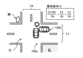
- Figure 5 shows the formula for collision condition A and how a collision occurs when collision condition A is met.
- Figure 6 shows the formula for collision condition B and how a collision occurs when collision condition B is met.
- Lo Distance [m] between the vehicle 100b and the center point (hereinafter referred to as "center point ⁇ ") of the intersection of the driving lanes Lxs and Lxm at the intersection CL.
- do Total length of vehicle 100b [m]
- Vo Vehicle 100b speed [m/s]
- Le Distance [m] between the vehicle 100a and the center point ⁇ of the intersection of the driving lanes Lxs and Lxm at the intersection CL.
- the stereo camera mounted on vehicle 100a captures an image of the area ahead of vehicle 100a and outputs the resulting stereo image to IPU 11c.
- IPU 11c generates a distance image based on the stereo image captured by the stereo camera and outputs the image to driving environment detection unit 11d.
- Driving environment detection unit 11d performs a predetermined pattern matching on the distance image generated by IPU 11c, and detects driving lane Lxm, driving lane Lxs, intersection CL, vehicle 100b, and convex mirror MR.
- Convex mirror MR corresponds to a specific example of a structure different from the road surface that exists near intersection CL.
- the stereo image includes an intersection CL that is in front of vehicle 100a in driving lane Lxm, but vehicle 100b traveling in driving lane Lxs is blocked by a building BL and is not included.
- the driving environment detection unit 11d cannot detect vehicle 100b using the distance image.
- the convex mirror MR has a reflective surface that can allow light Lw from the headlights 29 to reach vehicle 100b.
- the driving environment recognition unit 13c uses the road map information acquired from external communication to detect the driving lane Lxm, the driving lane Lxs, the intersection CL, the vehicle 100b, and the curve mirror MR.
- the road map information acquired from external communication includes information on the vehicle 100b.
- the driving environment recognition unit 13c can detect the vehicle 100b using the road map information acquired from external communication.
- the vehicle position estimation unit 13b acquires the position coordinates of the vehicle 100a based on the positioning signal received by the GNSS receiver 17.
- the vehicle position estimation unit 13b further acquires the vehicle speed (the speed of the vehicle 100a) detected by the vehicle speed sensor 15.
- the vehicle position estimation unit 13b further acquires the overall length of the vehicle 100a. Note that if the overall length of the vehicle 100a is stored in advance, for example, in the memory of the vehicle position estimation unit 13b, the vehicle position estimation unit 13b acquires the overall length of the vehicle 100a by reading the overall length of the vehicle 100a from the memory.
- the driving_ECU 21 acquires road information Da, vehicle information Db, and structure information Dc based on various information obtained from the driving environment detection unit 11d, the vehicle position estimation unit 13b, and the driving environment recognition unit 13c (step S101).
- the road information Da includes information about the driving lane Lxm, the driving lane Lxs, and the intersection CL detected by the driving environment detection unit 11d or the driving environment recognition unit 13c.
- the vehicle information Db includes information about the vehicle 100a acquired from the vehicle position estimation unit 13b (e.g., position information, speed (vehicle speed) information), and information about the vehicle 100b acquired from the driving environment detection unit 11d or the driving environment recognition unit 13c (e.g., position information, speed (vehicle speed) information).
- the structure information Dc includes information about the structure detected by the driving environment recognition unit 13c (e.g., position information).
- the travel_ECU 21 determines whether an intersection CL exists ahead of the vehicle 100a (step S102). If the road information Da includes information on the intersection CL (step S102; Y), the travel_ECU 21 determines whether the lane (travel lane Lxm) on which the vehicle 100a is traveling is the priority road Lm (step S103). If the road information Da includes information on the priority road Lm (step S103; Y), the travel_ECU 21 determines whether a vehicle (target vehicle) 100b traveling on a non-priority road Ls exists (step S104). If the vehicle information Db includes information on the vehicle 100b (step S104; Y), the travel_ECU 21 determines whether a reflector exists at the intersection CL (step S105). If the structure information Dc includes information on a curve mirror MR, which is a reflector (step S105; Y), the travel_ECU 21 executes a collision calculation (step S106).
- the traveling_ECU 21 calculates two collision conditions (collision condition A, collision condition B) using road information Da, vehicle information Db, and structure information Dc. If the traveling_ECU 21 calculates the two collision conditions (collision condition A, collision condition B) and finds that the vehicles 100a and 100b satisfy either of the two collision conditions (collision condition A, collision condition B) (step S107; Y), the traveling_ECU 21 generates a control signal to emit light Lw from the headlights 29 toward the convex mirror MR and outputs it to the HL_ECU 25.
- the traveling_ECU 21 determines that there is a possibility of a collision (interference) between the vehicles 100a and 100b, it generates a control signal to emit light Lw from the headlights 29 toward the convex mirror MR and outputs it to the HL_ECU 25.
- the HL_ECU 25 receives the control signal from the travel_ECU 21, it sets the optical axis direction of the light Lw of the headlight 29 based on the received control signal, and controls the headlight 29 to irradiate the light Lw in the set optical axis direction.
- the headlight 29 irradiates the light Lw to the vehicle 100b via the curved mirror MR (step S108, see FIG. 7).
- the traveling_ECU 21 executes step S101 if any of the following conditions is met in each of the above steps.
- step S102; N When the road information Da does not include information on the intersection CL (step S102; N)
- step S103; N When the road information Da does not include information on the priority road Lm
- step S104; N When the vehicle information Db does not include information on the vehicle 100b (step S104; N)
- step S105; N When the structure information Dc does not include information on the curved mirror MR, which is a reflector
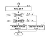
- the traveling_ECU 21 executes a collision avoidance calculation (step S109). Specifically, the traveling_ECU 21 determines whether the distance Le between the vehicle 100a and the center point ⁇ of the intersection of the driving lanes Lxs and Lxm at the intersection CL is longer than the stopping distance of the vehicle 100a (step S110). As a result, if the distance Le is longer than the stopping distance of the vehicle 100a, the traveling_ECU 21 determines that the collision can be avoided (step S110; Y). At this time, the traveling_ECU 21 determines whether the driver of the vehicle 100a can see the vehicle 100b (step S111). Specifically, the traveling_ECU 21 determines whether the vehicle 100b is included in the stereo image obtained by the stereo camera.
- the driving_ECU 21 determines that the driver can see the vehicle 100b (step S111; Y), and does not perform control such as deceleration control or collision warning for the vehicle 100a.
- the BK_ECU 24 outputs a drive signal to the brake actuator 28, thereby generating a braking force for each wheel by the brake wheel cylinder, forcibly decelerating the vehicle (step S112). Furthermore, the collision warning sound generating device generates a collision warning sound (step S112). In this way, danger notification and collision avoidance are performed.
- a control signal is sent to the HL_ECU 25 to emit light Lw from the headlights 29 toward the projectile, the curved mirror MR.
- deceleration control and collision warnings are not performed on vehicle 100a simply because vehicle 100b is traveling on the non-priority road Ls.
- vehicle 100b is approaching an intersection CL where the priority road Lm and non-priority road Ls intersect, and is traveling on the non-priority road Ls. Furthermore, based on data (road information Da, vehicle information Db, and structure information Dc) indicating that a curve mirror MR is present near the intersection CL, the possibility of vehicle 100b colliding (interfering) with vehicle 100a is determined. As a result, deceleration control and collision warnings are not performed on vehicle 100a simply because vehicle 100b is traveling on the non-priority road Ls. As a result, it is possible to reduce the frequency of bothersome deceleration control and collision warnings while improving safety.
- road information Da, vehicle information Db, and structure information Dc are acquired from sensors installed in vehicle 100a and the network environment NW, it is possible to more accurately determine the possibility of vehicle 100b colliding (interfering) with vehicle 100a compared to when road information Da, vehicle information Db, and structure information Dc are generated only by sensors installed in vehicle 100a.
- the driving environment detection unit 11d may detect the vehicle 100b reflected on the reflecting surface of the curved mirror MR, which is a reflector, based on the stereo image captured by the stereo camera. In this case, the driving environment detection unit 11d may estimate the position and speed of the vehicle 100b based on the image data of the vehicle 100b reflected on the curved mirror MR, and determine the possibility of the vehicle 100b colliding (interfering) with the vehicle 100a based on the estimation result. In this case, even if the vehicle 100b is in the blind spot of the driver of the vehicle 100a, it is possible to determine the possibility of the vehicle 100b colliding (interfering) with the vehicle 100a.
- the convex mirror MR is exemplified as a reflector (structure) that reflects the light Lw from the headlight 29.
- a reflector having a reflective surface that can allow the light Lw from the headlight 29 to reach the vehicle 100b may be used instead of the convex mirror MR.
- a building or wall having a scattering surface that can allow the light Lw from the headlight 29 to reach the vehicle 100b may be used instead of the convex mirror MR. Even in this case, the light Lw from the headlight 29 can reach the vehicle 100b, so that the frequency of bothersome deceleration control and collision warning can be reduced while improving safety.
- the traveling_ECU 21 may output a control signal to the HL_ECU 25 to emit the light Lw of the headlights 29 toward the curved mirror MR, and then generate a control signal to turn off the light Lw of the headlights 29 and output it to the HL_ECU 25.
- the traveling_ECU 21 may generate a control signal to turn off the light Lw of the headlights 29 and output it to the HL_ECU 25 when, for example, the vehicle 100a and the vehicle 100b no longer satisfy either of the two collision conditions (collision condition A and collision condition B). In this case, it is possible to prevent unnecessary light Lw from being continuously output from the headlights 29.
- the travel_ECU 21 may acquire road information Da, vehicle information Db, and structure information Dc based on various data of the sensor detection area SR obtained from various sensors mounted on the vehicle 100a, for example, as shown in FIG. 8.
- the road information Da includes information on the driving lane Lxm, the driving lane Lxs, and the intersection CL detected by the driving environment recognition unit 13c.
- the vehicle information Db includes information on the speed (vehicle speed) of the vehicle 100a acquired from the vehicle position estimation unit 13b and information on the vehicle 100b acquired from the driving environment recognition unit 13c.
- the structure information Dc includes information on the structure detected by the driving environment recognition unit 13c. Even in this case, it is possible to reduce the frequency of bothersome deceleration control and collision warning while improving safety.
- the driving control device 10 may have an alert light 31 in addition to the headlight 29, as shown in FIG. 9.
- the alert light 31 is also connected to the output side of the HL_ECU 25.
- the alert light 31 is a dedicated light capable of irradiating the above-mentioned "structures on the road” or the above-mentioned "structures around the road” with light.
- the alert light 31 is provided, for example, at the front end of the vehicle 100a.
- the HL_ECU 25 outputs a drive signal to the alert light 31 to control the on/off and optical axis of the alert light 31.
- the alert light 31 switches on/off the alert light 31 and changes the direction of the optical axis of the light emitted from the alert light 31 based on the drive signal from the HL_ECU 25.
- the traveling_ECU 21 when the vehicle 100a and the vehicle 100b satisfy either of the two collision conditions (collision condition A or collision condition B) as a result of the calculation of the two collision conditions (collision condition A or collision condition B) by the traveling_ECU 21 (step S107; Y), the traveling_ECU 21 generates a control signal to cause the notification light 31 to emit light Lw toward the convex mirror MR.
- the HL_ECU 25 sets the optical axis direction of the light Lw of the notification light 31 based on the input control signal, and controls the notification light 31 to irradiate the light Lw in the set optical axis direction.
- the notification light 31 irradiates the light Lw toward the vehicle 100b via the convex mirror MR (step S108, see FIG. 7).
- the notification light 31 is used in addition to the headlight 29.
- the notification light 31 can be suitable for illuminating a reflector such as a curved mirror MR.
- a reflector such as a curved mirror MR.
- the driver of vehicle 100b can be more effectively made aware of the presence of vehicle 100a.
- the present disclosure can have the following configuration.
- a control unit capable of performing driving assistance is provided, The control unit is acquiring data indicating that a second road intersecting with a first road ahead of a first road on which a first vehicle is traveling, that a second vehicle is approaching an intersection on the second road intersecting with the first road, and that a structure different from a road surface is present near the intersection; After acquiring the data, generate a first control signal for emitting headlight light toward the structure, and transmit the first control signal to a drive circuit of the headlight.
- the first road is a priority road having one or more lanes in each direction,
- the driving assistance device according to any one of claims 1 to 5, wherein the second road is a non-priority road in relation to the first road.
- the driving assistance device is capable of transmitting the first control signal to a drive circuit of the headlight when it determines that the second vehicle may interfere with the first vehicle.
- the structure is a curved mirror.
- the control unit is capable of determining the possibility of the second vehicle interfering with the first vehicle based on image data of the second vehicle reflected in the curve mirror.
- the driving assistance device according to any one of (1) to (5), wherein the structure is a building or a wall having a reflective or scattering surface that allows headlight light to reach the second vehicle.
- the driving assistance device is capable of determining a possibility that the second vehicle will interfere with the first vehicle based on the data.
- the driving assistance device according to any one of (1) to (7) wherein the control unit is capable of acquiring the data from a device provided in the first vehicle.
- the control unit is capable of acquiring the data from a first device provided in the first vehicle and a second device provided at or near the intersection.
- the control unit is capable of generating a second control signal for turning off the headlights after transmitting the first control signal to the drive circuit, and transmitting the second control signal to the drive circuit.
- the driving assistance device according to any one of (1) to (10), wherein the headlight is a headlight of the first vehicle.
- a control unit capable of performing driving assistance is provided, The control unit is acquiring data indicating that a second road intersecting with a first road ahead of a first road on which a first vehicle is traveling, that a second vehicle is approaching an intersection on the second road intersecting with the first road, and that a structure different from a road surface is present near the intersection; After acquiring the data, the vehicle is capable of generating a first control signal for emitting headlight light toward the structure and transmitting the first control signal to a drive circuit of the headlight.
- (13) acquiring data indicating that a second road intersecting with a first road ahead of a first road on which a first vehicle is traveling, that a second vehicle is approaching an intersection on the second road intersecting with the first road, and that a structure different from a road surface is present near the intersection; After acquiring the data, generating a first control signal for emitting headlight light toward the structure, and transmitting the first control signal to a drive circuit of the headlight.
- At least one processor e.g., a central processing unit (CPU)), at least one application specific integrated circuit (ASIC) and/or at least one field programmable gate array (FPGA).
- the at least one processor may be configured to execute all or part of the various functions of the driving control device 10 shown in FIG. 1 and 9 by reading instructions from at least one non-transitory and tangible computer-readable medium.
- Such media may take various forms, including, but not limited to, various magnetic media such as hard disks, various optical media such as CDs or DVDs, and various semiconductor memories (i.e., semiconductor circuits) such as volatile or non-volatile memories. Volatile memories may include DRAM and SRAM.
Landscapes
- Engineering & Computer Science (AREA)
- Mechanical Engineering (AREA)
- Traffic Control Systems (AREA)
Abstract
Selon un mode de réalisation de la présente invention, un dispositif d'aide à la conduite est pourvu d'une unité de commande capable d'aider à la conduite. L'unité de commande est capable de réaliser les fonctions (1) et (2) ci-dessous. (1) L'acquisition de données indiquant qu'une seconde route croisant une première route sur laquelle se déplace un premier véhicule est présente à l'avant de la première route, un second véhicule s'approchant d'une intersection croisant la première route est présent sur la seconde route, et une structure différente de la surface de route est présente à proximité de l'intersection. Suite à l'acquisition des données, un signal de commande qui entraîne la génération d'une émission par des phares vers la structure, et la transmission du signal de commande à un circuit de commande des phares.
Priority Applications (1)
| Application Number | Priority Date | Filing Date | Title |
|---|---|---|---|
| PCT/JP2023/030239 WO2025041286A1 (fr) | 2023-08-23 | 2023-08-23 | Dispositif d'aide à la conduite, véhicule, et procédé d'aide à la conduite |
Applications Claiming Priority (1)
| Application Number | Priority Date | Filing Date | Title |
|---|---|---|---|
| PCT/JP2023/030239 WO2025041286A1 (fr) | 2023-08-23 | 2023-08-23 | Dispositif d'aide à la conduite, véhicule, et procédé d'aide à la conduite |
Publications (1)
| Publication Number | Publication Date |
|---|---|
| WO2025041286A1 true WO2025041286A1 (fr) | 2025-02-27 |
Family
ID=94731787
Family Applications (1)
| Application Number | Title | Priority Date | Filing Date |
|---|---|---|---|
| PCT/JP2023/030239 Pending WO2025041286A1 (fr) | 2023-08-23 | 2023-08-23 | Dispositif d'aide à la conduite, véhicule, et procédé d'aide à la conduite |
Country Status (1)
| Country | Link |
|---|---|
| WO (1) | WO2025041286A1 (fr) |
Citations (4)
| Publication number | Priority date | Publication date | Assignee | Title |
|---|---|---|---|---|
| JP2005234999A (ja) * | 2004-02-20 | 2005-09-02 | Fuji Heavy Ind Ltd | 車両用運転支援装置 |
| WO2018138842A1 (fr) * | 2017-01-26 | 2018-08-02 | 三菱電機株式会社 | Dispositif de commande d'irradiation et procédé d'irradiation |
| JP2021170243A (ja) * | 2020-04-16 | 2021-10-28 | 株式会社Subaru | 車両の運転支援装置 |
| JP2023053532A (ja) * | 2021-10-01 | 2023-04-13 | 株式会社小糸製作所 | 車両用灯具 |
-
2023
- 2023-08-23 WO PCT/JP2023/030239 patent/WO2025041286A1/fr active Pending
Patent Citations (4)
| Publication number | Priority date | Publication date | Assignee | Title |
|---|---|---|---|---|
| JP2005234999A (ja) * | 2004-02-20 | 2005-09-02 | Fuji Heavy Ind Ltd | 車両用運転支援装置 |
| WO2018138842A1 (fr) * | 2017-01-26 | 2018-08-02 | 三菱電機株式会社 | Dispositif de commande d'irradiation et procédé d'irradiation |
| JP2021170243A (ja) * | 2020-04-16 | 2021-10-28 | 株式会社Subaru | 車両の運転支援装置 |
| JP2023053532A (ja) * | 2021-10-01 | 2023-04-13 | 株式会社小糸製作所 | 車両用灯具 |
Similar Documents
| Publication | Publication Date | Title |
|---|---|---|
| CN110356402B (zh) | 车辆控制装置、车辆控制方法及存储介质 | |
| JP6885462B2 (ja) | 運転支援装置及び運転支援方法 | |
| JP7431697B2 (ja) | 車両の走行制御装置及び車両の走行制御システム | |
| JP7590847B2 (ja) | 車両の走行制御装置 | |
| CN115339446B (zh) | 驾驶辅助装置 | |
| JP7538656B2 (ja) | 車両の走行制御装置 | |
| JP7549503B2 (ja) | 走行制御装置 | |
| JP7606383B2 (ja) | 車両の走行制御装置 | |
| CN106573618A (zh) | 车辆的行驶控制装置及方法 | |
| CN110799403A (zh) | 车辆控制装置 | |
| JP7287440B2 (ja) | 車両制御装置 | |
| CN112874513A (zh) | 驾驶支援装置 | |
| CN114651286A (zh) | 避障动作 | |
| CN116802709A (zh) | 显示控制装置和显示控制方法 | |
| JP7598215B2 (ja) | 車両の走行制御装置 | |
| JP2020045039A (ja) | 車両制御方法及び車両制御装置 | |
| JP7791678B2 (ja) | 車両の走行制御装置 | |
| JP7514167B2 (ja) | 車両の運転支援装置 | |
| JP2023148089A (ja) | 車両制御装置、車両制御方法、およびプログラム | |
| JP7160706B2 (ja) | 道路認識装置 | |
| JP7537548B2 (ja) | 車両制御装置 | |
| JP7652164B2 (ja) | 車両用制御装置及び車両用制御方法 | |
| WO2025041286A1 (fr) | Dispositif d'aide à la conduite, véhicule, et procédé d'aide à la conduite | |
| JP7538749B2 (ja) | 車両判別装置 | |
| JP7698498B2 (ja) | 運転支援装置 |
Legal Events
| Date | Code | Title | Description |
|---|---|---|---|
| 121 | Ep: the epo has been informed by wipo that ep was designated in this application |
Ref document number: 23949746 Country of ref document: EP Kind code of ref document: A1 |
|
| ENP | Entry into the national phase |
Ref document number: 2025541233 Country of ref document: JP Kind code of ref document: A |
|
| WWE | Wipo information: entry into national phase |
Ref document number: 2025541233 Country of ref document: JP |