WO2025041286A1 - Driving assistance device, vehicle, and driving assistance method - Google Patents
Driving assistance device, vehicle, and driving assistance method Download PDFInfo
- Publication number
- WO2025041286A1 WO2025041286A1 PCT/JP2023/030239 JP2023030239W WO2025041286A1 WO 2025041286 A1 WO2025041286 A1 WO 2025041286A1 JP 2023030239 W JP2023030239 W JP 2023030239W WO 2025041286 A1 WO2025041286 A1 WO 2025041286A1
- Authority
- WO
- WIPO (PCT)
- Prior art keywords
- vehicle
- road
- information
- intersection
- driving
- Prior art date
- Legal status (The legal status is an assumption and is not a legal conclusion. Google has not performed a legal analysis and makes no representation as to the accuracy of the status listed.)
- Pending
Links
Images


Classifications
-
- B—PERFORMING OPERATIONS; TRANSPORTING
- B60—VEHICLES IN GENERAL
- B60Q—ARRANGEMENT OF SIGNALLING OR LIGHTING DEVICES, THE MOUNTING OR SUPPORTING THEREOF OR CIRCUITS THEREFOR, FOR VEHICLES IN GENERAL
- B60Q1/00—Arrangement of optical signalling or lighting devices, the mounting or supporting thereof or circuits therefor
- B60Q1/02—Arrangement of optical signalling or lighting devices, the mounting or supporting thereof or circuits therefor the devices being primarily intended to illuminate the way ahead or to illuminate other areas of way or environments
- B60Q1/24—Arrangement of optical signalling or lighting devices, the mounting or supporting thereof or circuits therefor the devices being primarily intended to illuminate the way ahead or to illuminate other areas of way or environments for lighting other areas than only the way ahead
Definitions
- This disclosure relates to a driving assistance device mounted on a vehicle, the vehicle, and a driving assistance method.
- a driving assistance device includes a control unit capable of performing driving assistance.
- the control unit is capable of performing the following (A1) and (A2).
- (A1) acquiring data indicating that a second road intersecting the first road exists ahead of a first road on which a first vehicle is traveling, that a second vehicle is approaching an intersection on the second road that intersects with the first road, and that a structure different from the road surface exists near the intersection;
- (A2) after acquiring the above data, generating a control signal to emit headlight light toward the structure, and transmitting the control signal to a headlight drive circuit.
- a vehicle includes a control unit capable of performing driving assistance.
- the control unit is capable of performing the following (B1) and (B2).
- B1) acquiring data indicating that a second road intersecting the first road exists ahead of a first road on which a first vehicle is traveling, that a second vehicle is approaching an intersection on the second road that intersects with the first road, and that a structure different from the road surface exists near the intersection;
- B2) after acquiring the above data, generating a control signal to emit headlight light toward the structure, and transmitting the control signal to a headlight drive circuit.
- FIG. 1 is a diagram illustrating a schematic configuration example of a cruise control system according to a first embodiment of the present disclosure.
- FIG. 2 is a diagram showing an example of a danger notification procedure in the cruise control system of FIG.
- FIG. 3 is a diagram showing an example of a collision avoidance procedure in the cruise control system of FIG.
- FIG. 4 is a diagram showing an example of a traffic situation ahead of the host vehicle.
- FIG. 5 is a diagram showing an example of a collision condition at an intersection.
- FIG. 6 is a diagram showing another example of a collision condition at an intersection.
- FIG. 7 is a diagram showing an example of the danger notification in step S108 of FIG. FIG.
- FIG. 8 is a diagram illustrating an example of how various pieces of information are acquired in the cruise control system according to the second embodiment of the present disclosure.
- FIG. 9 is a diagram illustrating a modified example of the schematic configuration of the cruise control system according to each embodiment.
- FIG. 10 is a diagram showing a hypothetical example of a traffic situation.
- Patent Document 1 discloses a technology that, when there is a blind spot in front of the vehicle, appropriately decelerates the vehicle when it is about to pass through the blind spot without making the driver feel unsafe.
- the invention described in Patent Document 2 discloses a technology that warns the driver that a vehicle will appear from the blind spot when the vehicle makes a right turn when there is a vehicle in the blind spot of an oncoming vehicle traveling in front of the vehicle.
- the invention described in Patent Document 3 discloses a technology that determines the risk of an accident based on vehicle information around the vehicle and driver's line of sight information obtained by sensors, and issues a warning according to the accident risk.
- Patent Documents 1 to 3 if the driver of a vehicle traveling in the blind spot is unaware of the risk of collision with the vehicle, there is a risk of the vehicle colliding with the vehicle that appears from the blind spot. In some cases, the driver of the vehicle may continue to drive the vehicle without slowing down or traveling slowly, even when the driver is aware of the presence of a vehicle (hereinafter referred to as the "target vehicle") that is at risk of colliding with the vehicle. In such cases, there is a very high risk of a collision between the vehicle and the target vehicle.
- the target vehicle a vehicle
- Figure 10 shows a hypothetical example of a traffic situation.
- Vehicle (host vehicle) 100a is traveling on a road with one lane on each side.
- This road with one lane on each side is made up of a driving lane Lxm in which vehicle 100a is traveling, and an oncoming lane Lym that runs along the driving lane Lxm via a center line.
- An intersection CL is provided ahead of vehicle 100a on this road with one lane on each side.
- This road with one lane on each side is a wired road Lm in relation to the road that intersects with this road with one lane on each side at the intersection CL.
- vehicle 100a is traveling on a wired road Lm.
- the road intersecting the wired road Lm at the intersection CL is a non-priority road Ls in relation to the wired road Lm.
- a part of the non-priority road Ls is a blind spot (blind spot area DR) caused by a building BL, and in the blind spot area DR, a vehicle (target vehicle) 100b is traveling toward the intersection CL.
- the non-priority road Ls is composed of a driving lane Lxs in which the vehicle 100b is traveling, and an oncoming lane Lys that is provided along the driving lane Lxs via a center line. There are no traffic lights installed at the intersection CL.
- vehicle 100a The driver of vehicle 100a is aware that vehicle 100a is traveling on wired road Lm. Therefore, vehicle 100a is about to enter intersection CL without slowing down. At this time, vehicle 100b is traveling toward intersection CL on non-priority road Ls. However, vehicle 100b is traveling in a blind spot DR for the driver of vehicle 100a, and the driver of vehicle 100a is unaware of the presence of vehicle 100b.
- the inventors of the present application therefore came up with the idea of notifying the driver of vehicle 100b of the presence of vehicle 100a as a way to reduce the risk of collision between vehicle 100a and vehicle 100b in a specific traffic situation in which vehicle 100a and vehicle 100b are attempting to enter intersection CL where wired road Lm and non-priority road Ls intersect. Below, we will explain in detail the driving control system that achieves this.
- Fig. 1 shows a schematic configuration example of a cruise control system 1 according to an embodiment of the present disclosure.
- the cruise control system 1 includes cruise control devices 10 mounted on a plurality of vehicles, and a control device 200 provided in a network environment NW to which the plurality of cruise control devices 10 are connected via wireless communication.
- the cruise control device 10 corresponds to a specific example of a "driving assistance device" according to an embodiment of the present disclosure.
- the control device 200 sequentially integrates and updates road map information transmitted from the driving control device 10 of each vehicle and devices installed on the road or in its vicinity (e.g., at or near an intersection CL), and transmits the updated road map information to each vehicle.
- the control device 200 has, for example, a road map information integration_ECU 201 and a transceiver 202.
- the road map boundary information integration ECU 201 integrates road map information collected from multiple vehicles via the transceiver 202, and sequentially updates the road map information surrounding the vehicle on the road.
- the road map information is, for example, a dynamic map, and has static information and quasi-static information that mainly constitute road information, and quasi-dynamic information and dynamic information that mainly constitute traffic information.
- the static information that makes up road information is composed of information that requires updates within one month, such as roads, structures on roads, structures around roads, lane information, road surface information, and permanent regulation information.
- roads include, for example, road locations and shapes, intersections, and road attributes (for example, national roads, prefectural roads, city roads, private roads, priority roads, non-priority roads, general roads, and expressways).
- Structures on roads include, for example, traffic signs, traffic lights, convex mirrors, and pedestrian bridges.
- Structures around roads include, for example, various buildings and parks.
- the semi-dynamic information that makes up traffic information is made up of information that requires updates within one minute, such as the actual traffic congestion situation at the time of observation, driving restrictions, temporary driving impediments such as fallen objects and obstacles, actual accident conditions, and narrow-area weather information.
- the dynamic information that constitutes the traffic information is composed of information that requires updating every second, such as information sent and exchanged between moving objects, information on currently displayed traffic signals, information on pedestrians and bicycles at intersections, and information on vehicles traveling on roads.
- Such road map information is maintained and updated periodically until the next information is received from each vehicle, and the updated road map information is appropriately transmitted to each vehicle via the transceiver 202.
- the driving control device 10 has a driving environment recognition unit 11 and a locator unit 12 as units for recognizing the driving environment around the vehicle.
- the driving control device 10 also has a driving control unit (hereinafter referred to as "driving_ECU") 21, an engine control unit (hereinafter referred to as “E/G_ECU”) 22, a power steering control unit (hereinafter referred to as “PS_ECU”) 23, a brake control unit (hereinafter referred to as "BK_ECU”) 24, and a headlamp control unit (hereinafter referred to as "HL_ECU”) 25.
- These control units 21 to 25 are connected together with the driving environment recognition unit 11 and the locator unit 12 via an in-vehicle communication line such as a CAN (Controller Area Network).
- the driving_ECU 21 corresponds to a specific example of a "control unit” according to an embodiment of the present disclosure.
- the HL_ECU 25 corresponds to a specific example of a "drive circuit” according to an embodiment of
- the travel_ECU 21 controls the vehicle according to, for example, a driving mode.
- the driving modes include a manual driving mode and a driving control mode.
- the manual driving mode is a driving mode that requires the driver to maintain steering, and is a driving mode in which the vehicle is driven according to the driver's driving operations, such as steering, accelerator, and brake operations.
- the driving control mode is a driving mode that supports the driver in driving operations by the driver to increase the safety of pedestrians and other vehicles around the vehicle (host vehicle). In the driving control mode, for example, when the vehicle (host vehicle) approaches an intersection and the traffic light at the intersection changes from green to yellow and then to red, the driving_ECU 21 controls the vehicle (host vehicle) to stop at a stop line near the intersection. The detailed processing content in the driving control mode will be described later.
- a throttle actuator 26 is connected to the output side of the E/G_ECU 22. This throttle actuator 26 opens and closes the throttle valve of an electronically controlled throttle provided in the throttle body of the engine.
- the E/G_ECU 22 controls the operation of the throttle actuator 26 by outputting a drive signal to the throttle actuator 26.
- the throttle actuator 26 opens and closes the throttle valve based on the drive signal from the E/G_ECU 22 to adjust the intake air flow rate, thereby generating the desired engine output.
- An electric power steering motor 27 is connected to the output side of the PS_ECU 23. This electric power steering motor 27 applies steering torque to the steering mechanism by the rotational force of the motor.
- the PS_ECU 23 controls the operation of the electric power steering motor 27 by outputting a drive signal to the electric power steering motor 27.
- the electric power steering motor 27 performs lane keeping driving control, which keeps the vehicle traveling in the current driving lane, and lane change control, which moves the vehicle to an adjacent lane (lane change control for overtaking control, etc.), based on the drive signal from the PS_ECU 23.
- a brake actuator 28 is connected to the output side of the BK_ECU 24. This brake actuator 28 adjusts the brake hydraulic pressure supplied to the brake wheel cylinders provided on each wheel.
- the BK_ECU 24 controls the operation of the brake actuator 28 by outputting a drive signal to the brake actuator 28. Based on the drive signal from the BK_ECU 24, the brake actuator 28 generates a braking force on each wheel using the brake wheel cylinders, forcibly slowing down the wheels.
- Headlights 29 are connected to the output side of the HL_ECU 25. These headlights 29 mainly irradiate the road surface ahead of the vehicle with light.
- the headlights 29 are provided, for example, at the front end of the vehicle 100a.
- the headlights 29 irradiate, for example, the above-mentioned "structures on the road” or the above-mentioned "structures around the road” with light.
- the HL_ECU 25 outputs a drive signal to the headlights 29 to control the on/off and optical axis of the headlights 29. Based on the drive signal from the HL_ECU 25, the headlights 29 switch the on/off of the headlights 29 and change the direction of the optical axis of the light emitted from the headlights 29.
- the driving environment recognition unit 11 is fixed, for example, to the center of the upper part of the interior front of the vehicle.
- This driving environment recognition unit 11 has an on-board camera (stereo camera) consisting of a main camera 11a and a sub-camera 11b, an image processing unit (IPU) 11c, and a driving environment detection unit 11d.
- stereo camera stereo camera
- IPU image processing unit
- the main camera 11a and the sub-camera 11b are autonomous sensors that sense the real space around the vehicle.
- the main camera 11a and the sub-camera 11b are, for example, arranged at symmetrical positions on either side of the central part in the width direction of the vehicle, and capture stereo images of the area in front of the vehicle from different viewpoints.
- the IPU 11c generates a distance image calculated from the amount of deviation in the positions of corresponding objects based on a pair of stereo images of the area in front of the vehicle captured by the main camera 11a and the sub-camera 11b.
- the driving environment detection unit 11d determines the lane markings that divide the road around the vehicle based on the distance image received from the IPU 11c.
- the driving environment detection unit 11d further determines, for example, the road curvature [1/m] of the markings that divide the left and right sides of the road (driving lane) on which the vehicle is traveling, and the width between the left and right markings (vehicle width).
- the driving environment detection unit 11d further performs, for example, a predetermined pattern matching on the distance image to detect lanes and three-dimensional objects such as structures that exist around the vehicle.
- the driving environment detection unit 11d when detecting a three-dimensional object in the driving environment detection unit 11d, for example, the type of the three-dimensional object, the distance to the three-dimensional object, the speed of the three-dimensional object, and the relative speed between the three-dimensional object and the vehicle (host vehicle) are detected.
- three-dimensional objects to be detected include traffic lights, intersections, road signs, stop lines, other vehicles, pedestrians, and various buildings.
- the driving environment detection unit 11d outputs, for example, information on the detected three-dimensional object to the driving_ECU 21.
- the locator unit 12 estimates the position of the vehicle (own vehicle position) on a road map, and has a locator calculation unit 13 that estimates the own vehicle position. Sensors required for estimating the vehicle position (own vehicle position) are connected to the input side of this locator calculation unit 13. Such sensors include, for example, an acceleration sensor 14, a vehicle speed sensor 15, a gyro sensor 16, and a GNSS receiver 17.
- the acceleration sensor 14 detects the longitudinal acceleration of the vehicle.
- the vehicle speed sensor 15 detects the speed of the vehicle.
- the gyro sensor 16 detects the angular velocity or angular acceleration of the vehicle.
- the GNSS receiver 17 receives positioning signals transmitted from multiple positioning satellites.
- a transceiver 18 is connected to the locator calculation unit 13 for transmitting and receiving information to and from the control device 200, as well as transmitting and receiving information to and from other vehicles.
- a high-precision road map database 19 is connected to the locator calculation unit 13.
- the high-precision road map database 19 is a large-capacity storage medium such as an HDD, and stores high-precision road map information (dynamic map).
- This high-precision road map information like the road map information contained in the road map information integration_ECU 201, has static information and quasi-static information that mainly constitute road information, and quasi-dynamic information and dynamic information that mainly constitute traffic information.
- the locator calculation unit 13 includes, for example, a map information acquisition unit 13a, a vehicle position estimation unit 13b, and a driving environment recognition unit 13c.
- the vehicle position estimation unit 13b acquires the position coordinates of the vehicle (own vehicle) based on the positioning signal received by the GNSS receiver 17.
- the vehicle position estimation unit 13b also performs map matching of the acquired position coordinates on the route map information to estimate the vehicle's position on the road map.
- the map information acquisition unit 13a acquires map information of a predetermined range including the vehicle (own vehicle) from map information stored in the high-precision road map database 19 based on the position coordinates of the vehicle (own vehicle) acquired by the vehicle position estimation unit 13b.
- the vehicle position estimation unit 13b switches to autonomous navigation, which estimates the vehicle's position based on the vehicle speed detected by the vehicle speed sensor 15, the angular velocity detected by the gyro sensor 16, and the longitudinal acceleration detected by the acceleration sensor 14, and estimates the vehicle's position on the road map.
- the vehicle position estimation unit 13b estimates the position of the vehicle (own vehicle position) on the road map based on the positioning signal received by the GNSS receiver 17 or information detected by the gyro sensor 16, etc., as described above, and then determines the road type, etc. of the road on which the vehicle (own vehicle) is traveling based on the estimated own vehicle position on the road map.
- the driving environment recognition unit 13c uses road map information acquired by external communication (roadside-to-vehicle communication and vehicle-to-vehicle communication) via the transceiver 18 to update the road map information stored in the high-precision road map database 19 to the latest state.
- This information update is performed not only for static information, but also for quasi-static information, quasi-dynamic information, and dynamic information.
- the road map information is composed of road information and traffic information acquired by communication outside the vehicle, and information on moving bodies such as vehicles traveling on roads is updated in approximately real time.
- the driving environment recognition unit 13c verifies the road map information based on the driving environment information recognized by the driving environment recognition unit 11, and updates the road map information stored in the high-precision road map database 19 to the latest state.
- This information update is performed not only for static information, but also for quasi-static information, quasi-dynamic information, and dynamic information. As a result, information on moving objects such as vehicles traveling on roads recognized by the driving environment recognition unit 11 is updated in real time.
- the road map information updated in this manner is transmitted to the control device 200 and vehicles surrounding the vehicle (host vehicle) by road-to-vehicle communication and vehicle-to-vehicle communication via the transceiver 18. Furthermore, the driving environment recognition unit 13c outputs, from the updated road map information, map information of a predetermined range including the host vehicle position estimated by the vehicle position estimation unit 13b, together with the host vehicle position (vehicle position information), to the driving_ECU 21.
- FIG. 2 shows an example of a danger notification procedure in the cruise control system 1.
- FIG. 3 shows the procedure following FIG. 2, specifically, an example of a collision avoidance procedure in the cruise control system 1.
- FIG. 4 shows an example of a traffic situation in steps S101 to S107 in FIG. 2.
- FIG. 5 and FIG. 6 show an example of a collision situation between a vehicle (host vehicle) 100a and a vehicle (target vehicle) 100b.
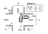
- FIG. 5 shows an example of one of the collision conditions (collision condition A) between the vehicles 100a and 100b.
- FIG. 6 shows an example of one of the collision conditions (collision condition B) between the vehicles 100a and 100b.
- FIG. 7 shows an example of a danger notification in step S108 in FIG. 2.
- vehicle (host vehicle) 100a is traveling on a road with one lane on each side.
- Vehicle 100a corresponds to a specific example of a "first vehicle” according to an embodiment of the present disclosure.
- This road with one lane on each side is composed of a driving lane Lxm in which vehicle 100a is traveling, and an oncoming lane Lym that is provided along the driving lane Lxm via a center line.
- An intersection CL is provided in front of vehicle 100a on this road with one lane on each side.
- This road with one lane on each side is a wired road Lm in relation to the road that intersects with this road with one lane on each side at the intersection CL.
- vehicle 100a is traveling on a wired road Lm.
- the road that intersects with the wired road Lm at the intersection CL is a non-priority road Ls in relation to the wired road Lm.
- a vehicle (target vehicle) 100b is traveling toward the intersection CL.
- the vehicle 100b corresponds to a specific example of a "second vehicle” according to an embodiment of the present disclosure.
- the non-priority road Ls is composed of a driving lane Lxs in which the vehicle 100b is traveling, and an oncoming lane Lys that is provided along the driving lane Lxs via a center line. There are no traffic lights installed at the intersection CL.
- vehicle 100a The driver of vehicle 100a is aware that vehicle 100a is traveling on wired road Lm. Therefore, vehicle 100a is about to enter intersection CL without slowing down. At this time, vehicle 100b is traveling toward intersection CL on non-priority road Ls. However, vehicle 100b is traveling in a blind spot DR for the driver of vehicle 100a, and the driver of vehicle 100a is unaware of the presence of vehicle 100b.
- the conditions for a collision between vehicle 100a and vehicle 100b at intersection CL are either of the following two collision conditions (collision condition A, collision condition B).
- Figure 5 shows the formula for collision condition A and how a collision occurs when collision condition A is met.
- Figure 6 shows the formula for collision condition B and how a collision occurs when collision condition B is met.
- Lo Distance [m] between the vehicle 100b and the center point (hereinafter referred to as "center point ⁇ ") of the intersection of the driving lanes Lxs and Lxm at the intersection CL.
- do Total length of vehicle 100b [m]
- Vo Vehicle 100b speed [m/s]
- Le Distance [m] between the vehicle 100a and the center point ⁇ of the intersection of the driving lanes Lxs and Lxm at the intersection CL.
- the stereo camera mounted on vehicle 100a captures an image of the area ahead of vehicle 100a and outputs the resulting stereo image to IPU 11c.
- IPU 11c generates a distance image based on the stereo image captured by the stereo camera and outputs the image to driving environment detection unit 11d.
- Driving environment detection unit 11d performs a predetermined pattern matching on the distance image generated by IPU 11c, and detects driving lane Lxm, driving lane Lxs, intersection CL, vehicle 100b, and convex mirror MR.
- Convex mirror MR corresponds to a specific example of a structure different from the road surface that exists near intersection CL.
- the stereo image includes an intersection CL that is in front of vehicle 100a in driving lane Lxm, but vehicle 100b traveling in driving lane Lxs is blocked by a building BL and is not included.
- the driving environment detection unit 11d cannot detect vehicle 100b using the distance image.
- the convex mirror MR has a reflective surface that can allow light Lw from the headlights 29 to reach vehicle 100b.
- the driving environment recognition unit 13c uses the road map information acquired from external communication to detect the driving lane Lxm, the driving lane Lxs, the intersection CL, the vehicle 100b, and the curve mirror MR.
- the road map information acquired from external communication includes information on the vehicle 100b.
- the driving environment recognition unit 13c can detect the vehicle 100b using the road map information acquired from external communication.
- the vehicle position estimation unit 13b acquires the position coordinates of the vehicle 100a based on the positioning signal received by the GNSS receiver 17.
- the vehicle position estimation unit 13b further acquires the vehicle speed (the speed of the vehicle 100a) detected by the vehicle speed sensor 15.
- the vehicle position estimation unit 13b further acquires the overall length of the vehicle 100a. Note that if the overall length of the vehicle 100a is stored in advance, for example, in the memory of the vehicle position estimation unit 13b, the vehicle position estimation unit 13b acquires the overall length of the vehicle 100a by reading the overall length of the vehicle 100a from the memory.
- the driving_ECU 21 acquires road information Da, vehicle information Db, and structure information Dc based on various information obtained from the driving environment detection unit 11d, the vehicle position estimation unit 13b, and the driving environment recognition unit 13c (step S101).
- the road information Da includes information about the driving lane Lxm, the driving lane Lxs, and the intersection CL detected by the driving environment detection unit 11d or the driving environment recognition unit 13c.
- the vehicle information Db includes information about the vehicle 100a acquired from the vehicle position estimation unit 13b (e.g., position information, speed (vehicle speed) information), and information about the vehicle 100b acquired from the driving environment detection unit 11d or the driving environment recognition unit 13c (e.g., position information, speed (vehicle speed) information).
- the structure information Dc includes information about the structure detected by the driving environment recognition unit 13c (e.g., position information).
- the travel_ECU 21 determines whether an intersection CL exists ahead of the vehicle 100a (step S102). If the road information Da includes information on the intersection CL (step S102; Y), the travel_ECU 21 determines whether the lane (travel lane Lxm) on which the vehicle 100a is traveling is the priority road Lm (step S103). If the road information Da includes information on the priority road Lm (step S103; Y), the travel_ECU 21 determines whether a vehicle (target vehicle) 100b traveling on a non-priority road Ls exists (step S104). If the vehicle information Db includes information on the vehicle 100b (step S104; Y), the travel_ECU 21 determines whether a reflector exists at the intersection CL (step S105). If the structure information Dc includes information on a curve mirror MR, which is a reflector (step S105; Y), the travel_ECU 21 executes a collision calculation (step S106).
- the traveling_ECU 21 calculates two collision conditions (collision condition A, collision condition B) using road information Da, vehicle information Db, and structure information Dc. If the traveling_ECU 21 calculates the two collision conditions (collision condition A, collision condition B) and finds that the vehicles 100a and 100b satisfy either of the two collision conditions (collision condition A, collision condition B) (step S107; Y), the traveling_ECU 21 generates a control signal to emit light Lw from the headlights 29 toward the convex mirror MR and outputs it to the HL_ECU 25.
- the traveling_ECU 21 determines that there is a possibility of a collision (interference) between the vehicles 100a and 100b, it generates a control signal to emit light Lw from the headlights 29 toward the convex mirror MR and outputs it to the HL_ECU 25.
- the HL_ECU 25 receives the control signal from the travel_ECU 21, it sets the optical axis direction of the light Lw of the headlight 29 based on the received control signal, and controls the headlight 29 to irradiate the light Lw in the set optical axis direction.
- the headlight 29 irradiates the light Lw to the vehicle 100b via the curved mirror MR (step S108, see FIG. 7).
- the traveling_ECU 21 executes step S101 if any of the following conditions is met in each of the above steps.
- step S102; N When the road information Da does not include information on the intersection CL (step S102; N)
- step S103; N When the road information Da does not include information on the priority road Lm
- step S104; N When the vehicle information Db does not include information on the vehicle 100b (step S104; N)
- step S105; N When the structure information Dc does not include information on the curved mirror MR, which is a reflector
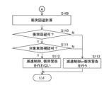
- the traveling_ECU 21 executes a collision avoidance calculation (step S109). Specifically, the traveling_ECU 21 determines whether the distance Le between the vehicle 100a and the center point ⁇ of the intersection of the driving lanes Lxs and Lxm at the intersection CL is longer than the stopping distance of the vehicle 100a (step S110). As a result, if the distance Le is longer than the stopping distance of the vehicle 100a, the traveling_ECU 21 determines that the collision can be avoided (step S110; Y). At this time, the traveling_ECU 21 determines whether the driver of the vehicle 100a can see the vehicle 100b (step S111). Specifically, the traveling_ECU 21 determines whether the vehicle 100b is included in the stereo image obtained by the stereo camera.
- the driving_ECU 21 determines that the driver can see the vehicle 100b (step S111; Y), and does not perform control such as deceleration control or collision warning for the vehicle 100a.
- the BK_ECU 24 outputs a drive signal to the brake actuator 28, thereby generating a braking force for each wheel by the brake wheel cylinder, forcibly decelerating the vehicle (step S112). Furthermore, the collision warning sound generating device generates a collision warning sound (step S112). In this way, danger notification and collision avoidance are performed.
- a control signal is sent to the HL_ECU 25 to emit light Lw from the headlights 29 toward the projectile, the curved mirror MR.
- deceleration control and collision warnings are not performed on vehicle 100a simply because vehicle 100b is traveling on the non-priority road Ls.
- vehicle 100b is approaching an intersection CL where the priority road Lm and non-priority road Ls intersect, and is traveling on the non-priority road Ls. Furthermore, based on data (road information Da, vehicle information Db, and structure information Dc) indicating that a curve mirror MR is present near the intersection CL, the possibility of vehicle 100b colliding (interfering) with vehicle 100a is determined. As a result, deceleration control and collision warnings are not performed on vehicle 100a simply because vehicle 100b is traveling on the non-priority road Ls. As a result, it is possible to reduce the frequency of bothersome deceleration control and collision warnings while improving safety.
- road information Da, vehicle information Db, and structure information Dc are acquired from sensors installed in vehicle 100a and the network environment NW, it is possible to more accurately determine the possibility of vehicle 100b colliding (interfering) with vehicle 100a compared to when road information Da, vehicle information Db, and structure information Dc are generated only by sensors installed in vehicle 100a.
- the driving environment detection unit 11d may detect the vehicle 100b reflected on the reflecting surface of the curved mirror MR, which is a reflector, based on the stereo image captured by the stereo camera. In this case, the driving environment detection unit 11d may estimate the position and speed of the vehicle 100b based on the image data of the vehicle 100b reflected on the curved mirror MR, and determine the possibility of the vehicle 100b colliding (interfering) with the vehicle 100a based on the estimation result. In this case, even if the vehicle 100b is in the blind spot of the driver of the vehicle 100a, it is possible to determine the possibility of the vehicle 100b colliding (interfering) with the vehicle 100a.
- the convex mirror MR is exemplified as a reflector (structure) that reflects the light Lw from the headlight 29.
- a reflector having a reflective surface that can allow the light Lw from the headlight 29 to reach the vehicle 100b may be used instead of the convex mirror MR.
- a building or wall having a scattering surface that can allow the light Lw from the headlight 29 to reach the vehicle 100b may be used instead of the convex mirror MR. Even in this case, the light Lw from the headlight 29 can reach the vehicle 100b, so that the frequency of bothersome deceleration control and collision warning can be reduced while improving safety.
- the traveling_ECU 21 may output a control signal to the HL_ECU 25 to emit the light Lw of the headlights 29 toward the curved mirror MR, and then generate a control signal to turn off the light Lw of the headlights 29 and output it to the HL_ECU 25.
- the traveling_ECU 21 may generate a control signal to turn off the light Lw of the headlights 29 and output it to the HL_ECU 25 when, for example, the vehicle 100a and the vehicle 100b no longer satisfy either of the two collision conditions (collision condition A and collision condition B). In this case, it is possible to prevent unnecessary light Lw from being continuously output from the headlights 29.
- the travel_ECU 21 may acquire road information Da, vehicle information Db, and structure information Dc based on various data of the sensor detection area SR obtained from various sensors mounted on the vehicle 100a, for example, as shown in FIG. 8.
- the road information Da includes information on the driving lane Lxm, the driving lane Lxs, and the intersection CL detected by the driving environment recognition unit 13c.
- the vehicle information Db includes information on the speed (vehicle speed) of the vehicle 100a acquired from the vehicle position estimation unit 13b and information on the vehicle 100b acquired from the driving environment recognition unit 13c.
- the structure information Dc includes information on the structure detected by the driving environment recognition unit 13c. Even in this case, it is possible to reduce the frequency of bothersome deceleration control and collision warning while improving safety.
- the driving control device 10 may have an alert light 31 in addition to the headlight 29, as shown in FIG. 9.
- the alert light 31 is also connected to the output side of the HL_ECU 25.
- the alert light 31 is a dedicated light capable of irradiating the above-mentioned "structures on the road” or the above-mentioned "structures around the road” with light.
- the alert light 31 is provided, for example, at the front end of the vehicle 100a.
- the HL_ECU 25 outputs a drive signal to the alert light 31 to control the on/off and optical axis of the alert light 31.
- the alert light 31 switches on/off the alert light 31 and changes the direction of the optical axis of the light emitted from the alert light 31 based on the drive signal from the HL_ECU 25.
- the traveling_ECU 21 when the vehicle 100a and the vehicle 100b satisfy either of the two collision conditions (collision condition A or collision condition B) as a result of the calculation of the two collision conditions (collision condition A or collision condition B) by the traveling_ECU 21 (step S107; Y), the traveling_ECU 21 generates a control signal to cause the notification light 31 to emit light Lw toward the convex mirror MR.
- the HL_ECU 25 sets the optical axis direction of the light Lw of the notification light 31 based on the input control signal, and controls the notification light 31 to irradiate the light Lw in the set optical axis direction.
- the notification light 31 irradiates the light Lw toward the vehicle 100b via the convex mirror MR (step S108, see FIG. 7).
- the notification light 31 is used in addition to the headlight 29.
- the notification light 31 can be suitable for illuminating a reflector such as a curved mirror MR.
- a reflector such as a curved mirror MR.
- the driver of vehicle 100b can be more effectively made aware of the presence of vehicle 100a.
- the present disclosure can have the following configuration.
- a control unit capable of performing driving assistance is provided, The control unit is acquiring data indicating that a second road intersecting with a first road ahead of a first road on which a first vehicle is traveling, that a second vehicle is approaching an intersection on the second road intersecting with the first road, and that a structure different from a road surface is present near the intersection; After acquiring the data, generate a first control signal for emitting headlight light toward the structure, and transmit the first control signal to a drive circuit of the headlight.
- the first road is a priority road having one or more lanes in each direction,
- the driving assistance device according to any one of claims 1 to 5, wherein the second road is a non-priority road in relation to the first road.
- the driving assistance device is capable of transmitting the first control signal to a drive circuit of the headlight when it determines that the second vehicle may interfere with the first vehicle.
- the structure is a curved mirror.
- the control unit is capable of determining the possibility of the second vehicle interfering with the first vehicle based on image data of the second vehicle reflected in the curve mirror.
- the driving assistance device according to any one of (1) to (5), wherein the structure is a building or a wall having a reflective or scattering surface that allows headlight light to reach the second vehicle.
- the driving assistance device is capable of determining a possibility that the second vehicle will interfere with the first vehicle based on the data.
- the driving assistance device according to any one of (1) to (7) wherein the control unit is capable of acquiring the data from a device provided in the first vehicle.
- the control unit is capable of acquiring the data from a first device provided in the first vehicle and a second device provided at or near the intersection.
- the control unit is capable of generating a second control signal for turning off the headlights after transmitting the first control signal to the drive circuit, and transmitting the second control signal to the drive circuit.
- the driving assistance device according to any one of (1) to (10), wherein the headlight is a headlight of the first vehicle.
- a control unit capable of performing driving assistance is provided, The control unit is acquiring data indicating that a second road intersecting with a first road ahead of a first road on which a first vehicle is traveling, that a second vehicle is approaching an intersection on the second road intersecting with the first road, and that a structure different from a road surface is present near the intersection; After acquiring the data, the vehicle is capable of generating a first control signal for emitting headlight light toward the structure and transmitting the first control signal to a drive circuit of the headlight.
- (13) acquiring data indicating that a second road intersecting with a first road ahead of a first road on which a first vehicle is traveling, that a second vehicle is approaching an intersection on the second road intersecting with the first road, and that a structure different from a road surface is present near the intersection; After acquiring the data, generating a first control signal for emitting headlight light toward the structure, and transmitting the first control signal to a drive circuit of the headlight.
- At least one processor e.g., a central processing unit (CPU)), at least one application specific integrated circuit (ASIC) and/or at least one field programmable gate array (FPGA).
- the at least one processor may be configured to execute all or part of the various functions of the driving control device 10 shown in FIG. 1 and 9 by reading instructions from at least one non-transitory and tangible computer-readable medium.
- Such media may take various forms, including, but not limited to, various magnetic media such as hard disks, various optical media such as CDs or DVDs, and various semiconductor memories (i.e., semiconductor circuits) such as volatile or non-volatile memories. Volatile memories may include DRAM and SRAM.
Landscapes
- Engineering & Computer Science (AREA)
- Mechanical Engineering (AREA)
- Traffic Control Systems (AREA)
Abstract
Description
本開示は、車両に搭載される運転支援装置、車両および運転支援方法に関する。 This disclosure relates to a driving assistance device mounted on a vehicle, the vehicle, and a driving assistance method.
近年、自動車等の車両においては、ドライバの運転操作の負担を軽減するとともに、安全性の向上を実現することを目的として、ドライバの運転操作を支援するための運転支援装置が実用化されている。この種の運転支援装置に関する技術が、例えば、特許文献1~3に開示されている。 In recent years, driving assistance devices have been put into practical use to assist the driver in driving operations in vehicles such as automobiles, with the aim of reducing the burden of driving operations on the driver and improving safety. Technologies related to this type of driving assistance device are disclosed, for example, in Patent Documents 1 to 3.
本開示の第1の側面に係る運転支援装置は、運転支援を行うことの可能な制御部を備えている。制御部は、以下の(A1)、(A2)を行うことが可能となっている。
(A1)第1の車両が走行する第1の道路の前方に、第1の道路と交差する第2の道路が存在することと、第2の道路において第1の道路と交差する交差点に近づく第2の車両が存在することと、交差点付近に路面とは異なる構造体が存在することとを示すデータを取得すること
(A2)上記データを取得した後、構造体に向かって前照灯の光を発する制御信号を生成し、制御信号を前照灯の駆動回路に送信すること
A driving assistance device according to a first aspect of the present disclosure includes a control unit capable of performing driving assistance. The control unit is capable of performing the following (A1) and (A2).
(A1) acquiring data indicating that a second road intersecting the first road exists ahead of a first road on which a first vehicle is traveling, that a second vehicle is approaching an intersection on the second road that intersects with the first road, and that a structure different from the road surface exists near the intersection; (A2) after acquiring the above data, generating a control signal to emit headlight light toward the structure, and transmitting the control signal to a headlight drive circuit.
本開示の第2の側面に係る車両は、運転支援を行うことの可能な制御部を備えている。制御部は、以下の(B1)、(B2)を行うことが可能となっている。
(B1)第1の車両が走行する第1の道路の前方に、第1の道路と交差する第2の道路が存在することと、第2の道路において第1の道路と交差する交差点に近づく第2の車両が存在することと、交差点付近に路面とは異なる構造体が存在することとを示すデータを取得すること
(B2)上記データを取得した後、構造体に向かって前照灯の光を発する制御信号を生成し、制御信号を前照灯の駆動回路に送信すること
A vehicle according to a second aspect of the present disclosure includes a control unit capable of performing driving assistance. The control unit is capable of performing the following (B1) and (B2).
(B1) acquiring data indicating that a second road intersecting the first road exists ahead of a first road on which a first vehicle is traveling, that a second vehicle is approaching an intersection on the second road that intersects with the first road, and that a structure different from the road surface exists near the intersection; (B2) after acquiring the above data, generating a control signal to emit headlight light toward the structure, and transmitting the control signal to a headlight drive circuit.
本開示の第3の側面に係る運転支援方法は、以下の(C1)、(C2)を含む。
(C1)第1の車両が走行する第1の道路の前方に、第1の道路と交差する第2の道路が存在することと、第2の道路において第1の道路と交差する交差点に近づく第2の車両が存在することと、交差点付近に路面とは異なる構造体が存在することとを示すデータを取得すること
(C2)上記データを取得した後、構造体に向かって前照灯の光を発する制御信号を生成し、制御信号を前照灯の駆動回路に送信すること
A driving assistance method according to a third aspect of the present disclosure includes the following (C1) and (C2).
(C1) acquiring data indicating that a second road intersecting the first road exists ahead of a first road on which a first vehicle is traveling, that a second vehicle is approaching an intersection on the second road that intersects with the first road, and that a structure different from the road surface exists near the intersection; (C2) after acquiring the above data, generating a control signal to emit light from the headlights toward the structure, and transmitting the control signal to a drive circuit for the headlights.
添付図面は、本開示をさらに理解するために設けられており、本明細書に組み込まれるとともに、本明細書の一部を構成するものである。図面は、一実施の形態を示し、明細書とともに、本開示の原理を説明する役割を果たす。 The accompanying drawings are provided to provide a further understanding of the present disclosure and are incorporated in and constitute a part of this specification. The drawings illustrate one embodiment and, together with the specification, serve to explain the principles of the present disclosure.
以下、本開示の実施の形態について、図面を参照して詳細に説明する。 The following describes in detail the embodiments of the present disclosure with reference to the drawings.
<1.背景>
近年、自動車等の車両においては、ドライバの運転操作の負担を軽減するとともに、安全性の向上を実現することを目的として、ドライバの運転操作を支援するための運転支援装置が実用化されている。この種の運転支援装置に関する技術が、例えば、特許文献1~3に開示されている。
1. Background
In recent years, in vehicles such as automobiles, driving assistance devices for assisting the driver in driving operations have been put into practical use in order to reduce the burden of driving operations on the driver and to improve safety. Technologies related to this type of driving assistance device are disclosed in, for example, Patent Documents 1 to 3.
特許文献1に記載の発明では、自車両の前方に死角部分が存在するときに、自車両がその死角部分を通過しようとする際に、ドライバに危険を感じさせることなく適度に減速する技術が開示されている。特許文献2に記載の発明では、自車両の前方を走行する対向車両の死角に走行車両が存在するときに、自車両が右折する際に、死角から走行車両が現れることをドライバに警報する技術が開示されている。特許文献3に記載の発明では、センサにより得られた、自車両周辺の車両情報やドライバの視線情報に基づいて事故リスクを判定し、事故リスクに応じて警報を発する技術が開示されている。 The invention described in Patent Document 1 discloses a technology that, when there is a blind spot in front of the vehicle, appropriately decelerates the vehicle when it is about to pass through the blind spot without making the driver feel unsafe. The invention described in Patent Document 2 discloses a technology that warns the driver that a vehicle will appear from the blind spot when the vehicle makes a right turn when there is a vehicle in the blind spot of an oncoming vehicle traveling in front of the vehicle. The invention described in Patent Document 3 discloses a technology that determines the risk of an accident based on vehicle information around the vehicle and driver's line of sight information obtained by sensors, and issues a warning according to the accident risk.
しかし、各特許文献1~3に記載の発明では、死角を走行する車両のドライバが、自車両との衝突リスクがあることに気が付いていない場合には、自車両と、死角から現れた車両とが衝突するおそれがある。場合によっては、自車両のドライバは、自車両と衝突するリスクのある車両(以下、「対象車両」と称する。)が存在することを認識しているときであっても、減速や徐行をせずに自車両を走行させることもある。そのような場合には、自車両と対象車両とが衝突するおそれが非常に高い。 However, in the inventions described in Patent Documents 1 to 3, if the driver of a vehicle traveling in the blind spot is unaware of the risk of collision with the vehicle, there is a risk of the vehicle colliding with the vehicle that appears from the blind spot. In some cases, the driver of the vehicle may continue to drive the vehicle without slowing down or traveling slowly, even when the driver is aware of the presence of a vehicle (hereinafter referred to as the "target vehicle") that is at risk of colliding with the vehicle. In such cases, there is a very high risk of a collision between the vehicle and the target vehicle.
このように、従来の発明では、自車両の走行制御を行ったり、自車両のドライバに警報したりしたとしても、自車両と他の車両との衝突の可能性が高いという問題がある。そこで、本願発明者は、鋭意検討した結果、自車両の走行制御を行ったり、自車両のドライバに警報したりするだけでなく、対象車両のドライバに対して、自車両の存在を効果的に知らせることの可能な技術を想起した。以下に、交通状況の仮想事例を挙げて、今回新たに想起した技術の背景について説明する。 As described above, conventional inventions have a problem in that even if the vehicle's driving is controlled and the driver of the vehicle is alerted, there is still a high possibility of the vehicle colliding with another vehicle. As a result of extensive research, the inventors of the present application have come up with a technology that not only controls the vehicle's driving and alerts the driver of the vehicle, but also effectively notifies the driver of a target vehicle of the presence of the vehicle. Below, we will explain the background of this newly conceived technology by giving hypothetical examples of traffic conditions.
図10は、交通状況の仮想事例を表したものである。車両(自車両)100aは、片側1車線の道路を走行しているものとする。この片側1車線の道路は、車両100aが走行している走行車線Lxmと、中央線を介して走行車線Lxmに沿って設けられた対向車線Lymとにより構成されている。この片側1車線の道路には、車両100aの前方において、交差点CLが設けられている。この片側1車線の道路は、交差点CLにおいてこの片側1車線の道路と交差する道路との関係で、有線道路Lmとなっている。つまり、車両100aは、有線道路Lmを走行している。
Figure 10 shows a hypothetical example of a traffic situation. Vehicle (host vehicle) 100a is traveling on a road with one lane on each side. This road with one lane on each side is made up of a driving lane Lxm in which
一方、交差点CLにおいて有線道路Lmと交差する道路は、有線道路Lmとの関係で非優先道路Lsとなっている。車両100aのドライバから見たときに、非優先道路Lsの
一部は、建物BLによって死角(死角領域DR)となっており、死角領域DRには、車両(対象車両)100bが交差点CLに向かって走行している。非優先道路Lsは、車両100bが走行している走行車線Lxsと、中央線を介して走行車線Lxsに沿って設けられた対向車線Lysとにより構成されている。交差点CLには、信号機が設置されていない。
On the other hand, the road intersecting the wired road Lm at the intersection CL is a non-priority road Ls in relation to the wired road Lm. When viewed from the driver of the
車両100aのドライバは、車両100aが有線道路Lmを走行していることを認識している。そのため、車両100aは、減速せずに交差点CLに進入しようとしている。このとき、非優先道路Lsにおいて、車両100bが交差点CLに向かって走行している。しかし、車両100bは、車両100aのドライバにとっての死角領域DRを走行しており、車両100aのドライバは、車両100bの存在に気が付いていない。
The driver of
このような交通状況下では、車両100aと車両100bとが、交差点CLにおいて出会い頭の衝突事故を起こす可能性が高い。なお、仮に、建物BLが存在していない場合であっても、車両100aのドライバが、車両100aが有線道路Lmを走行していることを認識し、車両100aが減速せずに交差点CLに進入しようしており、さらに、車両100bのドライバは、車両100aの存在に気が付いていないこともある。このとき、車両100aと車両100bとが、交差点CLにおいて衝突事故を起こす可能性が高い。
Under such traffic conditions, there is a high possibility that
そこで、本願発明者は、有線道路Lmと非優先道路Lsとが交差する交差点CLに車両100aおよび車両100bが侵入しようとする特定の交通状況下での、車両100aと車両100bとの衝突リスクを低減する方策として、車両100aの存在を車両100bのドライバに知らせることを想起した。以下に、それを実現するための走行制御システムについて詳細に説明する。
The inventors of the present application therefore came up with the idea of notifying the driver of
<2.実施の形態>
[構成例]
図1は、本開示の一実施の形態に係る走行制御システム1の概略構成例を表したものである。走行制御システム1は、例えば、図1に示したように、複数の車両にそれぞれ搭載された走行制御装置10と、複数の走行制御装置10が無線通信を介して接続されるネットワーク環境NWに設けられる管制装置200とを備えている。走行制御装置10が、本開示の一実施の形態に係る「運転支援装置」の一具体例に相当する。
2. Preferred embodiment
[Configuration example]
Fig. 1 shows a schematic configuration example of a cruise control system 1 according to an embodiment of the present disclosure. As shown in Fig. 1, the cruise control system 1 includes
管制装置200は、各車両の走行制御装置10や、道路またはその近傍(例えば、交差点CLまたはその近傍)に設けられたデバイスから送信される道路地図情報を逐次統合して更新し、更新した道路地図情報を各車両に送信する。管制装置200は、例えば、道路地図情報統合_ECU201と、送受信機202とを有している。
The control device 200 sequentially integrates and updates road map information transmitted from the
道路地図境情報統合_ECU201は、送受信機202を通じて複数の車両から収集した道路地図情報を統合して、道路上の車両を取り巻く道路地図情報を逐次更新する。道路地図情報は、例えば、ダイナミックマップからなり、主として道路情報を構成する静的情報及び準静的情報と、主として交通情報を構成する準動的情報及び動的情報とを有している。
The road map boundary
道路情報を構成する静的情報は、例えば、道路や道路上の構造物、道路の周囲の構造物、車線情報、路面情報、恒久的な規制情報等、1ヶ月以内の更新頻度が求められる情報によって構成されている。「道路」には、例えば、道路の位置および形状、交差点、ならびに道路の属性(例えば、国道、県道、市道、私有道、優先道路、非優先道路、一般道、高速道路)等が含まれる。「道路上の構造物」には、例えば、交通標識、信号機、カーブミラー、歩道橋等が含まれる。「道路の周囲の構造物」には、例えば、各種建物、公園等が含まれる。 The static information that makes up road information is composed of information that requires updates within one month, such as roads, structures on roads, structures around roads, lane information, road surface information, and permanent regulation information. "Roads" include, for example, road locations and shapes, intersections, and road attributes (for example, national roads, prefectural roads, city roads, private roads, priority roads, non-priority roads, general roads, and expressways). "Structures on roads" include, for example, traffic signs, traffic lights, convex mirrors, and pedestrian bridges. "Structures around roads" include, for example, various buildings and parks.
道路情報を構成する準静的情報は、例えば、道路工事やイベント等による交通規制情報、広域気象情報、渋滞予測等、1時間以内での更新頻度が求められる情報によって構成されている。 The semi-static information that makes up road information is made up of information that needs to be updated within one hour, such as traffic regulation information due to road construction or events, wide-area weather information, and traffic congestion forecasts.
交通情報を構成する準動的情報は、例えば、観測時点における実際の渋滞状況や走行規制、落下物や障害物等、一時的な走行障害状況、実際の事故状態、狭域気象情報など、1分以内での更新頻度が求められる情報によって構成されている。 The semi-dynamic information that makes up traffic information is made up of information that requires updates within one minute, such as the actual traffic congestion situation at the time of observation, driving restrictions, temporary driving impediments such as fallen objects and obstacles, actual accident conditions, and narrow-area weather information.
交通情報を構成する動的情報は、例えば、移動体の間で送信・交換される情報や現在示されている信号の情報、交差点内の歩行者・自転車情報、道路を走行する車両情報等、1秒単位での更新頻度が求められる情報によって構成されている。このような道路地図情報は、各車両から次の情報を受信するまでの周期で維持・更新され、更新された道路地図情報は送受信機202を通じて各車両に適宜送信される。
The dynamic information that constitutes the traffic information is composed of information that requires updating every second, such as information sent and exchanged between moving objects, information on currently displayed traffic signals, information on pedestrians and bicycles at intersections, and information on vehicles traveling on roads. Such road map information is maintained and updated periodically until the next information is received from each vehicle, and the updated road map information is appropriately transmitted to each vehicle via the
走行制御装置10は、車両の周囲の走行環境を認識するためのユニットとして、走行環境認識ユニット11及びロケータユニット12を有している。また、走行制御装置10は、走行制御ユニット(以下、「走行_ECU」と称す)21と、エンジン制御ユニット(以下、「E/G_ECU」と称す)22と、パワーステアリング制御ユニット(以下、「PS_ECU」と称す)23と、ブレーキ制御ユニット(以下、「BK_ECU」と称す)24と、前照灯制御ユニット(以下、「HL_ECU」と称す)25を有している。これら各制御ユニット21~25は、走行環境認識ユニット11及びロケータユニット12と共に、CAN(Controller Area Network)等の車内通信回線を介して接続されている。走行_ECU21が、本開示の一実施の形態に係る「制御部」の一具体例に相当する。HL_ECU25が、本開示の一実施の形態に係る「駆動回路」の一具体例に相当する。
The driving
走行_ECU21は、例えば、運転モードに応じて車両を制御する。運転モードとしては、例えば、手動運転モードと、走行制御モードとが挙げられる。手動運転モードとは、ドライバによる保舵を必要とする運転モードであり、例えば、ドライバによるステアリング操作、アクセル操作およびブレーキ操作などの運転操作に従って、自車両を走行させる運転モードである。走行制御モードとは、ドライバによる運転操作において、車両(自車両)の周囲にいる歩行者や車両などの安全性を高めるためにドライバをサポートする運転モードである。走行_ECU21は、走行制御モードにおいて、例えば、交差点に車両(自車両)が近づいたときに、その交差点に設けられた信号機が青から黄色、そして赤色に変化したときに、車両(自車両)がその交差点付近にある停止線で停止するよう、車両を制御する。走行制御モードにおける詳細な処理内容については、後に詳述する。
The
E/G_ECU22の出力側には、スロットルアクチュエータ26が接続されている。このスロットルアクチュエータ26は、エンジンのスロットルボディに設けられている電子制御スロットルのスロットル弁を開閉動作させるものである。E/G_ECU22は、スロットルアクチュエータ26に対して駆動信号を出力することにより、スロットルアクチュエータ26の動作を制御する。スロットルアクチュエータ26は、E/G_ECU22からの駆動信号に基づいてスロットル弁を開閉動作させて吸入空気流量を調整することで、所望のエンジン出力を発生させる。
A
PS_ECU23の出力側には、電動パワステモータ27が接続されている。この電動パワステモータ27は、ステアリング機構にモータの回転力で操舵トルクを付与するものである。PS_ECU23は、電動パワステモータ27に対して駆動信号を出力することにより、電動パワステモータ27の動作を制御する。電動パワステモータ27は、自動運転では、PS_ECU23からの駆動信号に基づいて、現在の走行車線の走行を維持させる車線維持走行制御、および自車両を隣接車線へ移動させる車線変更制御(追越制御などのための車線変更制御)を実行する。
An electric
BK_ECU24の出力側には、ブレーキアクチュエータ28が接続されている。このブレーキアクチュエータ28は、各車輪に設けられているブレーキホイールシリンダに対して供給するブレーキ油圧を調整する。BK_ECU24は、ブレーキアクチュエータ28に対して駆動信号を出力することにより、ブレーキアクチュエータ28の動作を制御する。ブレーキアクチュエータ28は、BK_ECU24からの駆動信号に基づいて、ブレーキホイールシリンダにより各車輪に対してブレーキ力を発生させ、強制的に減速させる。
A
HL_ECU25の出力側には、ヘッドライト29が接続されている。このヘッドライト29は、主として車両の前方の路面を光で照射する。ヘッドライト29は、例えば、車両100aの前端部に設けられている。ヘッドライト29は、車両の前方の路面の他に、例えば、上述の「道路上の構造物」、または、上述の「道路の周囲の構造物」を光で照射する。HL_ECU25は、ヘッドライト29に対して駆動信号を出力することにより、ヘッドライト29の点灯・消灯および光軸を制御する。ヘッドライト29は、HL_ECU25からの駆動信号に基づいて、ヘッドライト29の点灯・消灯を切り替えたり、ヘッドライト29から発せられる光の光軸の向きを変化させたりする。
走行環境認識ユニット11は、例えば、車両の内前部の上部中央に固定されている。この走行環境認識ユニット11は、メインカメラ11aおよびサブカメラ11bからなる車載カメラ(ステレオカメラ)と、画像処理ユニット(IPU)11cと、走行環境検出部11dとを有している。
The driving
メインカメラ11aおよびサブカメラ11bは、車両の周辺の実空間をセンシングする自律センサである。メインカメラ11aおよびサブカメラ11bは、例えば、車両の、幅方向における中央部分を挟んで左右対称な位置に配置され、車両の前方を異なる視点からステレオ撮像する。
The
IPU11cは、メインカメラ11aおよびサブカメラ11bで撮像することにより得られた車両の前方の一対のステレオ画像に基づいて、対応する対象の位置のズレ量から求めた距離画像を生成する。
The
走行環境検出部11dは、例えば、IPU11cから受信した距離画像に基づき、車両の周辺の道路を区画する車線区画線を求める。走行環境検出部11dは、例えば、さらに、車両が走行する走行路(走行レーン)の左右を区画する区画線の道路曲率[1/m]、および左右区画線間の幅(車幅)を求める。走行環境検出部11dは、さらに、例えば、距離画像に対して所定のパターンマッチングなどを行い、車線や、車両の周辺に存在する構造物等の立体物を検出する。
The driving
ここで、走行環境検出部11dにおける立体物の検出では、例えば、立体物の種別、立体物までの距離、立体物の速度、立体物と車両(自車両)との相対速度などの検出が行われる。検出対象の立体物としては、例えば、信号機、交差点、道路標識、停止線、他の車両、歩行者、各種建物などが挙げられる。走行環境検出部11dは、例えば、検出した立体物の情報を走行_ECU21に出力する。
Here, when detecting a three-dimensional object in the driving
ロケータユニット12は、道路地図上の車両の位置(自車位置)を推定するものであり、自車位置を推定するロケータ演算部13を有している。このロケータ演算部13の入力側には、車両の位置(自車位置)を推定するに際して必要とするセンサ類が接続されている。そのようなセンサ類として、例えば、加速度センサ14、車速センサ15、ジャイロセンサ16、GNSS受信機17などが含まれている。加速度センサ14は、車両の前後加速度を検出する。車速センサ15は、車両の速度を検出する。ジャイロセンサ16は、車両の角速度または角加速度を検出する。GNSS受信機17は、複数の測位衛星から発信される測位信号を受信する。また、ロケータ演算部13には、管制装置200との間で情報の送受信を行うとともに、他の車両との間で情報の送受信を行うための送受信機18が接続されている。
The
また、ロケータ演算部13には、高精度道路地図データベース19が接続されている。高精度道路地図データベース19は、HDDなどの大容量記憶媒体であり、高精度な道路地図情報(ダイナミックマップ)が記憶されている。この高精度道路地図情報は、例えば、道路地図情報統合_ECU201に含まれる道路地図情報と同様に、主として道路情報を構成する静的情報および準静的情報と、主として交通情報を構成する準動的情報および動的情報とを有している。
Also, a high-precision road map database 19 is connected to the
ロケータ演算部13は、例えば、地図情報取得部13aと、車両位置推定部13bと、走行環境認識部13cとを有している。
The
車両位置推定部13bは、GNSS受信機17で受信した測位信号に基づき車両(自車両)の位置座標を取得する。また、車両位置推定部13bは、取得した位置座標をルート地図情報上にマップマッチングして、道路地図上の自車位置を推定する。地図情報取得部13aは、車両位置推定部13bで取得した車両(自車両)の位置座標に基づき、車両(自車両)を含む所定の範囲の地図情報を高精度道路地図データベース19に格納されている地図情報から取得する。
The vehicle position estimation unit 13b acquires the position coordinates of the vehicle (own vehicle) based on the positioning signal received by the
車両位置推定部13bは、トンネル内走行などのようにGNSS受信機17の感度低下により測位衛星からの有効な測位信号を受信することができない環境において、車速センサ15で検出した車速、ジャイロセンサ16で検出した角速度、および加速度センサ14で検出した前後加速度に基づいて自車位置を推定する自律航法に切換えて、道路地図上の自車位置を推定する。
In an environment where valid positioning signals from positioning satellites cannot be received due to reduced sensitivity of the
車両位置推定部13bは、上述のようにGNSS受信機17で受信した測位信号或いはジャイロセンサ16等で検出した情報等に基づいて道路地図上の車両の位置(自車位置)を推定すると、推定した道路地図上の自車位置に基づき、車両(自車両)が走行中の走行路の道路種別等を判定する。
The vehicle position estimation unit 13b estimates the position of the vehicle (own vehicle position) on the road map based on the positioning signal received by the
走行環境認識部13cは、送受信機18を通じた外部通信(路車間通信、および車車間通信)により取得した道路地図情報を用い、高精度道路地図データベース19に格納された道路地図情報を最新の状態に更新する。この情報更新は、静的情報のみならず、準静的情報、準動的情報、および動的情報についても行われる。これにより、道路地図情報は、車外との通信により取得した道路情報及び交通情報を含んで構成され、道路上を走行する車両等の移動体の情報が略リアルタイムで更新される。
The driving
走行環境認識部13cは、走行環境認識ユニット11により認識した走行環境情報に基づいて道路地図情報の検証を行い、高精度道路地図データベース19に格納された道路地図情報を最新の状態に更新する。この情報更新は、静的情報のみならず、準静的情報、準動的情報、及び、動的情報についても行われる。これにより、走行環境認識ユニット11により認識した道路上を走行する車両等の移動体の情報については、リアルタイムで更新される。
The driving
そして、このように更新された道路地図情報は、送受信機18を通じた路車間通信及び車車間通信により、管制装置200および車両(自車両)の周辺車両等に対して送信される。さらに、走行環境認識部13cは、更新された道路地図情報のうち、車両位置推定部13bにおいて推定した自車位置を含む所定の範囲の地図情報を、自車位置(車両位置情報)とともに、走行_ECU21に出力する。
Then, the road map information updated in this manner is transmitted to the control device 200 and vehicles surrounding the vehicle (host vehicle) by road-to-vehicle communication and vehicle-to-vehicle communication via the
次に、走行_ECU21について詳細に説明する。
Next, the
図2は、走行制御システム1における危険通知手順の一例を表したものである。図3は、図2に続く手順であり、具体的には、走行制御システム1における衝突回避手順の一例を表したものである。図4は、図2のステップS101~S107における交通状況の一例を表したものである。図5、図6は、車両(自車両)100aと、車両(対象車両)100bとの衝突状況の一例を表したものである。図5には、車両100aと車両100bとの衝突条件の1つ(衝突条件A)が例示されている。図6には、車両100aと車両100bとの衝突条件の1つ(衝突条件B)が例示されている。図7は、図2のステップS108における危険通知の一例を表したものである。
FIG. 2 shows an example of a danger notification procedure in the cruise control system 1. FIG. 3 shows the procedure following FIG. 2, specifically, an example of a collision avoidance procedure in the cruise control system 1. FIG. 4 shows an example of a traffic situation in steps S101 to S107 in FIG. 2. FIG. 5 and FIG. 6 show an example of a collision situation between a vehicle (host vehicle) 100a and a vehicle (target vehicle) 100b. FIG. 5 shows an example of one of the collision conditions (collision condition A) between the
図4では、車両(自車両)100aは、片側1車線の道路を走行しているものとする。車両100aが、本開示の一実施の形態に係る「第1車両」の一具体例に相当する。この片側1車線の道路は、車両100aが走行している走行車線Lxmと、中央線を介して走行車線Lxmに沿って設けられた対向車線Lymとにより構成されている。この片側1車線の道路には、車両100aの前方において、交差点CLが設けられている。この片側1車線の道路は、交差点CLにおいてこの片側1車線の道路と交差する道路との関係で、有線道路Lmとなっている。つまり、車両100aは、有線道路Lmを走行している。
In FIG. 4, vehicle (host vehicle) 100a is traveling on a road with one lane on each side.
一方、交差点CLにおいて有線道路Lmと交差する道路は、有線道路Lmとの関係で非優先道路Lsとなっている。車両100aのドライバから見たときに、非優先道路Lsの一部は、建物BLによって死角となっており、死角には、車両(対象車両)100bが交差点CLに向かって走行している。車両100bが、本開示の一実施の形態に係る「第2車両」の一具体例に相当する。非優先道路Lsは、車両100bが走行している走行車線Lxsと、中央線を介して走行車線Lxsに沿って設けられた対向車線Lysとにより構成されている。交差点CLには、信号機が設置されていない。
On the other hand, the road that intersects with the wired road Lm at the intersection CL is a non-priority road Ls in relation to the wired road Lm. When viewed from the driver of the
車両100aのドライバは、車両100aが有線道路Lmを走行していることを認識している。そのため、車両100aは、減速せずに交差点CLに進入しようとしている。このとき、非優先道路Lsにおいて、車両100bが交差点CLに向かって走行している。しかし、車両100bは、車両100aのドライバにとっての死角領域DRを走行しており、車両100aのドライバは、車両100bの存在に気が付いていない。
The driver of
このような交通状況下では、車両100aと車両100bとが、交差点CLにおいて出会い頭の衝突事故を起こす可能性が高い。なお、仮に、建物BLが存在していない場合であっても、車両100aのドライバが、車両100aが有線道路Lmを走行していることを認識し、車両100aが減速せずに交差点CLに進入しようしており、さらに、車両100bのドライバは、車両100aの存在に気が付いていないこともある。このとき、車両100aと車両100bとが、交差点CLにおいて衝突事故を起こす可能性が高い。
Under such traffic conditions, there is a high possibility that
車両100aと車両100bとが交差点CLにおいて衝突事故を起こす条件は、以下の2つの衝突条件(衝突条件A、衝突条件B)のいずれかである。図5には、衝突条件Aの式と、衝突条件Aを満たすときの衝突の様子が示されている。図6には、衝突条件Bの式と、衝突条件Bを満たすときの衝突の様子が示されている。
The conditions for a collision between
(衝突条件A)
(Lo+do)/Vo>Le/Ve>Lo/Vo
(衝突条件B)
(Le+de)/Ve>Lo/Vo>Le/Ve
(Collision condition A)
(Lo+do)/Vo>Le/Ve>Lo/Vo
(Collision condition B)
(Le+de)/Ve>Lo/Vo>Le/Ve
Lo:車両100bと、交差点CLにおける走行車線Lxsと走行車線Lxmとの交差部分の中心点(以下、「中心点α」と称する。)との距離[m]
do:車両100bの全長[m]
Vo:車両100bの速度[m/s]
Le:車両100aと、交差点CLにおける走行車線Lxsと走行車線Lxmとの交差部分の中心点αとの距離[m]
de:車両100aの全長[m]
Ve:車両100aの速度[m/s]
Lo/Vo:車両100bが中心点αに到達するまでの時間
(Lo+do)/Vo:車両100bが中心点αを通過するまでの時間
Le/Ve:車両100aが中心点αに到達するまでの時間
(Le+de)/Ve:車両100aが中心点αを通過するまでの時間
Lo: Distance [m] between the
do: Total length of
Vo:
Le: Distance [m] between the
de: total length of
Ve: Velocity of
Lo/Vo: Time until
まず、車両100aに設けられたステレオカメラは、車両100aの前方を撮像し、それにより得られたステレオ画像をIPU11cに出力する。IPU11cは、ステレオカメラで取得したステレオ画像に基づいて距離画像を生成し、走行環境検出部11dに出力する。走行環境検出部11dは、IPU11cで生成された距離画像に対して、所定のパターンマッチングなどを行い、走行車線Lxm、走行車線Lxs、交差点CL、車両100bおよびカーブミラーMRの検出を行う。カーブミラーMRは、交差点CL付近に存在する、路面とは異なる構造体の一具体例に相当する。
First, the stereo camera mounted on
ここで、ステレオ画像には、例えば、走行車線Lxmにおいて車両100aの前方に存在する交差点CLが含まれているが、走行車線Lxsを走行する車両100bが建物BLに遮られ、含まれていないとする。このとき、走行環境検出部11dは、距離画像を利用して車両100bを検出することができない。なお、カーブミラーMRは、走行車線Lxmを走行する車両100aのヘッドライト29からの光LwがカーブミラーMRの反射面に照射されると、ヘッドライト29からの光LwがカーブミラーMRの鏡面で反射され、走行車線Lxsの車両100bを照射する。つまり、カーブミラーMRは、ヘッドライト29からの光Lwを車両100bに届かせることの可能な反射面を有している。
Here, for example, the stereo image includes an intersection CL that is in front of
次に、走行環境認識部13cは、外部通信から取得した道路地図情報を利用して、走行車線Lxm、走行車線Lxs、交差点CL、車両100bおよびカーブミラーMRの検出を行う。ここで、外部通信から取得した道路地図情報に、車両100bの情報が含まれているとする。このとき、走行環境認識部13cは、外部通信から取得した道路地図情報を利用して、車両100bを検出することができる。
Next, the driving
車両位置推定部13bは、GNSS受信機17で受信した測位信号に基づき車両100aの位置座標を取得する。車両位置推定部13bは、さらに、車速センサ15で検出した車速(車両100aの速度)を取得する。車両位置推定部13bは、さらに、車両100aの全長を取得する。なお、車両100aの全長が、例えば、車両位置推定部13bのメモリにあらかじめ格納されている場合には、車両位置推定部13bは、メモリから車両100aの全長を読み出すことにより、車両100aの全長を取得する。
The vehicle position estimation unit 13b acquires the position coordinates of the
次に、走行_ECU21は、走行環境検出部11d、車両位置推定部13bおよび走行環境認識部13cから得られた各種情報に基づいて、道路情報Da、車両情報Dbおよび構造物情報Dcを取得する(ステップS101)。ここで、道路情報Daは、走行環境検出部11dまたは走行環境認識部13cで検出した走行車線Lxm、走行車線Lxsおよび交差点CLについての情報を含む。車両情報Dbは、車両位置推定部13bから取得した車両100aについての情報(例えば、位置情報、速度(車速)情報)と、走行環境検出部11dまたは走行環境認識部13cから取得した車両100bについての情報(例えば、位置情報、速度(車速)情報)とを含む。構造物情報Dcは、走行環境認識部13cで検出した構造物についての情報(例えば、位置情報)を含む。
Next, the
次に、走行_ECU21は、車両100aの前方に交差点CLが存在するか否かを判定する(ステップS102)。走行_ECU21は、道路情報Daに交差点CLの情報が含まれる場合(ステップS102;Y)、車両100aが走行する車線(走行車線Lxm)が優先道路Lmであるか否かを判定する(ステップS103)。走行_ECU21は、道路情報Daに優先道路Lmの情報が含まれる場合(ステップS103;Y)、非優先道路Lsを走行する車両(対象車両)100bが存在するか否かを判定する(ステップS104)。走行_ECU21は、車両情報Dbに車両100bの情報が含まれる場合(ステップS104;Y)、交差点CLに反射体が存在するか否かを判定する(ステップS105)。走行_ECU21は、構造物情報Dcに、反射体であるカーブミラーMRの情報が含まれる場合(ステップS105;Y)、衝突計算を実行する(ステップS106)。
Next, the
具体的には、走行_ECU21は、道路情報Da、車両情報Dbおよび構造物情報Dcを利用して、2つの衝突条件(衝突条件A、衝突条件B)を計算する。走行_ECU21は、2つの衝突条件(衝突条件A、衝突条件B)の計算を行った結果、車両100aおよび車両100bが2つの衝突条件(衝突条件A、衝突条件B)のいずれかを満たす場合(ステップS107;Y)、走行_ECU21は、カーブミラーMRに向かってヘッドライト29の光Lwを発する制御信号を生成し、HL_ECU25に出力する。つまり、走行_ECU21は、車両100aおよび車両100bが衝突(干渉)する可能性があると判断したときに、カーブミラーMRに向かってヘッドライト29の光Lwを発する制御信号を生成し、HL_ECU25に出力する。HL_ECU25は、走行_ECU21から上記制御信号が入力されると、入力された制御信号に基づいて、ヘッドライト29の光Lwの光軸方向を設定し、設定した光軸方向に光Lwを照射するよう、ヘッドライト29を制御する。その結果、ヘッドライト29は、カーブミラーMRを介して車両100bに光Lwを照射する(ステップS108、図7参照)。
Specifically, the
走行_ECU21は、上記の各ステップにおいて、以下のいずれかに該当する場合、ステップS101を実行する。
・道路情報Daに交差点CLの情報が含まれない場合(ステップS102;N)
・道路情報Daに優先道路Lmの情報が含まれない場合(ステップS103;N)
・車両情報Dbに車両100bの情報が含まれない場合(ステップS104;N)
・構造物情報Dcに、反射体であるカーブミラーMRの情報が含まれない場合(ステップS105;N)
The
When the road information Da does not include information on the intersection CL (step S102; N)
When the road information Da does not include information on the priority road Lm (step S103; N)
When the vehicle information Db does not include information on the
When the structure information Dc does not include information on the curved mirror MR, which is a reflector (step S105; N)
次に、走行_ECU21は、衝突回避計算を実行する(ステップS109)。具体的には、走行_ECU21は、車両100aと、交差点CLにおける走行車線Lxsと走行車線Lxmとの交差部分の中心点αとの距離Leが、車両100aの停止距離よりも長いか否かを判定する(ステップS110)。その結果、距離Leが車両100aの停止距離よりも長い場合には、走行_ECU21は、衝突回避可と判断する(ステップS110;Y)。このとき、走行_ECU21は、車両100aのドライバが車両100bを視認できるか否かを判定する(ステップS111)。具体的には、走行_ECU21は、ステレオカメラで得られたステレオ画像の中に車両100bが含まれているか否かを判定する。その結果、ステレオ画像の中に車両100bが含まれている場合には、走行_ECU21は、ドライバが車両100bを視認できると判断し(ステップS111;Y)、車両100aの減速制御や衝突警告等の制御を行わない。
Next, the
このとき、車両100aのドライバは、自己判断に基づいてブレーキ操作や、ギヤ操作等を行うことで、車両100bとの衝突を回避する。なお、車両100bのドライバが、車両100aの存在に気が付き、車両100bを減速するなどして、車両100aと車両100bとの衝突を回避した場合には、車両100aのドライバは、特段、ブレーキ操作や、ギヤ操作等を行わずに、交差点CLを通過することも可能である。
At this time, the driver of
一方、走行_ECU21は、ステップS110において、距離Leが車両100aの停止距離以下の場合には、衝突回避可困難と判断する(ステップS110;N)。また、走行_ECU21は、ステップS111において、ステレオ画像の中に車両100bが含まれていない場合には、ドライバが車両100bを視認することが困難であると判断する(ステップS111;N)。これらの場合、走行_ECU21は、車両100aの減速制御や衝突警告等の制御を行うと判断し、減速制御の指示をBK_ECU24に出力するとともに、衝突警告音を発生する指示を、衝突警告音を発することの可能な衝突警告音発生装置に出力する。その結果、BK_ECU24は、ブレーキアクチュエータ28に対して駆動信号を出力することにより、ブレーキホイールシリンダにより各車輪に対してブレーキ力を発生させ、強制的に減速させる(ステップS112)。さらに、衝突警告音発生装置は、衝突警告音を発生する(ステップS112)。このようにして、危険通知および衝突回避が実行される。
On the other hand, in step S110, if the distance Le is equal to or less than the stopping distance of the
[効果]
次に、本開示の一実施の形態に係る走行制御システム1の効果について説明する。
[effect]
Next, effects of the cruise control system 1 according to an embodiment of the present disclosure will be described.
本実施の形態では、優先道路Lmと非優先道路Lsとが交差する交差点CLに近づく車両100bが非優先道路Lsを走行しているとき、反射体であるカーブミラーMRに向かってヘッドライト29の光Lwを発する制御信号が生成され、HL_ECU25に送信される。これにより、車両100bが非優先道路Lsを走行しているというだけで、車両100aに対して減速制御や衝突警告を行うことが無い。その結果、安全性を向上させつつ、煩わしい減速制御や衝突警告の頻度を低減することができる。
In this embodiment, when
本実施の形態では、車両100bが車両100aと衝突(干渉)する可能性があると判断したときに、射体であるカーブミラーMRに向かってヘッドライト29の光Lwを発する制御信号がHL_ECU25に送信される。これにより、車両100bが非優先道路Lsを走行しているというだけで、車両100aに対して減速制御や衝突警告を行うことが無い。その結果、安全性を向上させつつ、煩わしい減速制御や衝突警告の頻度を低減することができる。
In this embodiment, when it is determined that there is a possibility that
本実施の形態では、優先道路Lmと非優先道路Lsとが交差する交差点CLに近づく車両100bが非優先道路Lsを走行しており、さらに、交差点CL付近にカーブミラーMRが存在することを示すデータ(道路情報Da、車両情報Dbおよび構造物情報Dc)に基づいて、車両100bが車両100aと衝突(干渉)する可能性が判断される。これにより、車両100bが非優先道路Lsを走行しているというだけで、車両100aに対して減速制御や衝突警告を行うことが無い。その結果、安全性を向上させつつ、煩わしい減速制御や衝突警告の頻度を低減することができる。
In this embodiment,
本実施の形態において、道路情報Da、車両情報Dbおよび構造物情報Dcが車両100aに設けられたセンサから取得される場合には、車両100aがネットワーク環境NWと通信することが困難なときであっても、安全性を向上させつつ、煩わしい減速制御や衝突警告の頻度を低減することができる。
In this embodiment, when road information Da, vehicle information Db, and structure information Dc are acquired from sensors installed in the
本実施の形態において、道路情報Da、車両情報Dbおよび構造物情報Dcが道路情報Da、車両情報Dbおよび構造物情報Dcが車両100aに設けられたセンサと、ネットワーク環境NWとから取得される場合には、車両100aに設けられたセンサだけで道路情報Da、車両情報Dbおよび構造物情報Dcを生成した場合と比べて、より精度よく、車両100bが車両100aと衝突(干渉)する可能性を判断することができる。
In this embodiment, when road information Da, vehicle information Db, and structure information Dc are acquired from sensors installed in
<3.変形例>
以上、実施の形態を挙げて本開示を説明したが、本開示はこの実施の形態に限定されず、種々の変形が可能である。
3. Modifications
Although the present disclosure has been described above by way of the embodiment, the present disclosure is not limited to this embodiment and various modifications are possible.
[変形例3-1]
上記実施の形態において、走行環境検出部11dは、ステレオカメラから得られたステレオ撮像に基づいて、反射体であるカーブミラーMRの反射面に写った車両100bを検出するようになっていてもよい。このとき、走行環境検出部11dは、カーブミラーMRに車両100bが写った画像データに基づいて、車両100bの位置や速度を推定し、その推定結果に基づいて、車両100bが車両100aと衝突(干渉)する可能性を判断するようにしてもよい。このようにした場合には、車両100bが車両100aのドライバの死角にある場合であっても、車両100bが車両100aと衝突(干渉)する可能性を判断することができる。
[Modification 3-1]
In the above embodiment, the driving
[変形例3-2]
上記実施の形態では、ヘッドライト29からの光Lwを反射させる反射体(構造体)として、カーブミラーMRが例示されていた。しかし、上記実施の形態およびその変形例において、カーブミラーMRの代わりに、ヘッドライト29からの光Lwを車両100bに届かせることの可能な反射面を有する反射体が用いられてもよい。また、上記実施の形態において、カーブミラーMRの代わりに、ヘッドライト29からの光Lwを車両100bに届かせることの可能な散乱面を有する建物もしくは壁が用いられてもよい。このようにした場合であっても、ヘッドライト29からの光Lwを車両100bに届かせることができるので、安全性を向上させつつ、煩わしい減速制御や衝突警告の頻度を低減することができる。
[Modification 3-2]
In the above embodiment, the convex mirror MR is exemplified as a reflector (structure) that reflects the light Lw from the
[変形例3-3]
上記実施の形態およびその変形例において、走行_ECU21は、カーブミラーMRに向かってヘッドライト29の光Lwを発する制御信号をHL_ECU25に出力した後、ヘッドライト29の光Lwの光を消灯する制御信号を生成し、HL_ECU25に出力してもよい。上記実施の形態およびその変形例において、走行_ECU21は、例えば、車両100aおよび車両100bが2つの衝突条件(衝突条件A、衝突条件B)のいずれも満たさなくなったとき、ヘッドライト29の光Lwの光を消灯する制御信号を生成し、HL_ECU25に出力してもよい。このようにした場合には、不要な光Lwがヘッドライト29から出力され続けることを避けることができる。
[Variation 3-3]
In the above embodiment and its modified examples, the
[変形例3-4]
上記実施の形態およびその変形例において、車両100aがネットワーク環境NWと通信することが困難な場合、走行_ECU21は、例えば、図8に示したように、車両100aに搭載された各種センサから得られた、センサ検出領域SRの各種データに基づいて、道路情報Da、車両情報Dbおよび構造物情報Dcを取得するようにしてもよい。ここで、道路情報Daは、走行環境認識部13cで検出した走行車線Lxm、走行車線Lxsおよび交差点CLについての情報を含む。車両情報Dbは、車両位置推定部13bから取得した車両100aの速度(車速)の情報と、走行環境認識部13cから取得した車両100bについての情報とを含む。構造物情報Dcは、走行環境認識部13cで検出した構造物についての情報を含む。このようにした場合であっても、安全性を向上させつつ、煩わしい減速制御や衝突警告の頻度を低減することができる。
[Modification 3-4]
In the above embodiment and its modified example, when it is difficult for the
[変形例3-5]
上記実施の形態およびその変形例において、走行制御装置10は、例えば図9に示したように、ヘッドライト29とは別に、報知用ライト31を有していてもよい。HL_ECU25の出力側には、ヘッドライト29の他に、報知用ライト31も接続されている。報知用ライト31は、上述の「道路上の構造物」、または、上述の「道路の周囲の構造物」を光で照射することの可能な専用のライトである。報知用ライト31は、例えば、車両100aの前端部に設けられている。HL_ECU25は、報知用ライト31に対して駆動信号を出力することにより、報知用ライト31の点灯・消灯および光軸を制御する。報知用ライト31は、HL_ECU25からの駆動信号に基づいて、報知用ライト31の点灯・消灯を切り替えたり、報知用ライト31から発せられる光の光軸の向きを変化させたりする。
[Modification 3-5]
In the above embodiment and its modified example, the driving
本変形例では、走行_ECU21は、2つの衝突条件(衝突条件A、衝突条件B)の計算を行った結果、車両100aおよび車両100bが2つの衝突条件(衝突条件A、衝突条件B)のいずれかを満たす場合(ステップS107;Y)、走行_ECU21は、カーブミラーMRに向かって報知用ライト31の光Lwを発する制御信号を生成する。HL_ECU25は、走行_ECU21から上記制御信号が入力されると、入力された制御信号に基づいて、報知用ライト31の光Lwの光軸方向を設定し、設定した光軸方向に光Lwを照射するよう、報知用ライト31を制御する。その結果、報知用ライト31は、カーブミラーMRを介して車両100bに光Lwを照射する(ステップS108、図7参照)。
In this modified example, when the
このように、本変形例では、ヘッドライト29とは別に、報知用ライト31が用いられる。このようにした場合には、カーブミラーMR等の反射体を照射するのに適した報知用ライト31を用いることができる。例えば、報知用ライト31の光源として、ヘッドライト29の光よりも発光強度の高い光や、ヘッドライト29の光の色とは異なる色の光を用いることも可能となる。その結果、車両100bのドライバに、より効果的に車両100aの存在を気付かせることができる。
In this way, in this modified example, the
なお、本明細書中に記載された効果は、あくまで例示である。本開示の効果は、本明細書中に記載された効果に限定されるものではない。本開示が、本明細書中に記載された効果以外の効果を持っていてもよい。 Note that the effects described in this specification are merely examples. The effects of this disclosure are not limited to the effects described in this specification. This disclosure may have effects other than those described in this specification.
また、例えば、本開示は以下のような構成を取ることができる。
(1)
運転支援を行うことの可能な制御部を備え、
前記制御部は、
第1の車両が走行する第1の道路の前方に、前記第1の道路と交差する第2の道路が存在することと、前記第2の道路において前記第1の道路と交差する交差点に近づく第2の車両が存在することと、前記交差点付近に路面とは異なる構造体が存在することとを示すデータを取得することと、
前記データを取得した後、前記構造体に向かって前照灯の光を発する第1の制御信号を生成し、前記第1の制御信号を前記前照灯の駆動回路に送信することと
を行うことが可能となっている
運転支援装置。
(2)
前記第1の道路は、片側1車線以上の優先道路であり、
前記第2の道路は、前記第1の道路との関係で非優先道路である
(1)に記載の運転支援装置。
(3)
前記制御部は、前記第2の車両が前記第1の車両と干渉する可能性があると判断したときに、前記第1の制御信号を前記前照灯の駆動回路に送信することが可能となっている
(1)または(2)に記載の運転支援装置。
(4)
前記構造体は、カーブミラーである
(1)ないし(3)のいずれか1つに記載の運転支援装置。
(5)
前記制御部は、前記カーブミラーに前記第2の車両が写った画像データに基づいて、前記第2の車両が前記第1の車両と干渉する可能性を判断することが可能となっている
(4)に記載の運転支援装置。
(6)
前記構造体は、前照灯の光を前記第2の車両に届かせることの可能な反射面もしくは散乱面を有する建物もしくは壁である
(1)ないし(5)のいずれか1つに記載の運転支援装置。
(7)
前記制御部は、前記データに基づいて、前記第2の車両が前記第1の車両と干渉する可能性を判断することが可能となっている
(3)に記載の運転支援装置。
(8)
前記制御部は、前記データを、前記第1の車両に設けられたデバイスから取得することが可能となっている
(1)ないし(7)のいずれか1つに記載の運転支援装置。
(9)
前記制御部は、前記データを、前記第1の車両に設けられた第1のデバイスと、前記交差点またはその近傍に設けられた第2のデバイスとから取得することが可能となっている
(1)ないし(7)のいずれか1つに記載の運転支援装置。
(10)
前記制御部は、前記第1の制御信号を前記駆動回路に送信した後、前記前照灯の光を消灯させる第2の制御信号を生成し、前記第2の制御信号を前記駆動回路に送信することが可能となっている
(1)ないし(9)のいずれか1つに記載の運転支援装置。
(11)
前記前照灯は、前記第1の車両のヘッドライトである
(1)ないし(10)のいずれか1つに記載の運転支援装置。
(12)
運転支援を行うことの可能な制御部を備え、
前記制御部は、
第1の車両が走行する第1の道路の前方に、前記第1の道路と交差する第2の道路が存在することと、前記第2の道路において前記第1の道路と交差する交差点に近づく第2の車両が存在することと、前記交差点付近に路面とは異なる構造体が存在することとを示すデータを取得することと、
前記データを取得した後、前記構造体に向かって前照灯の光を発する第1の制御信号を生成し、前記第1の制御信号を前記前照灯の駆動回路に送信することと
を行うことが可能となっている
車両。
(13)
第1の車両が走行する第1の道路の前方に、前記第1の道路と交差する第2の道路が存在することと、前記第2の道路において前記第1の道路と交差する交差点に近づく第2の車両が存在することと、前記交差点付近に路面とは異なる構造体が存在することとを示すデータを取得することと、
前記データを取得した後、前記構造体に向かって前照灯の光を発する第1の制御信号を生成し、前記第1の制御信号を前記前照灯の駆動回路に送信することと
を含む
運転支援方法。
Furthermore, for example, the present disclosure can have the following configuration.
(1)
A control unit capable of performing driving assistance is provided,
The control unit is
acquiring data indicating that a second road intersecting with a first road ahead of a first road on which a first vehicle is traveling, that a second vehicle is approaching an intersection on the second road intersecting with the first road, and that a structure different from a road surface is present near the intersection;
After acquiring the data, generate a first control signal for emitting headlight light toward the structure, and transmit the first control signal to a drive circuit of the headlight.
(2)
The first road is a priority road having one or more lanes in each direction,
The driving assistance device according to any one of claims 1 to 5, wherein the second road is a non-priority road in relation to the first road.
(3)
The driving assistance device according to claim 1, wherein the control unit is capable of transmitting the first control signal to a drive circuit of the headlight when it determines that the second vehicle may interfere with the first vehicle.
(4)
The driving assistance device according to any one of (1) to (3), wherein the structure is a curved mirror.
(5)
The control unit is capable of determining the possibility of the second vehicle interfering with the first vehicle based on image data of the second vehicle reflected in the curve mirror.
(6)
The driving assistance device according to any one of (1) to (5), wherein the structure is a building or a wall having a reflective or scattering surface that allows headlight light to reach the second vehicle.
(7)
The driving assistance device according to claim 3, wherein the control unit is capable of determining a possibility that the second vehicle will interfere with the first vehicle based on the data.
(8)
The driving assistance device according to any one of (1) to (7), wherein the control unit is capable of acquiring the data from a device provided in the first vehicle.
(9)
The control unit is capable of acquiring the data from a first device provided in the first vehicle and a second device provided at or near the intersection. The driving assistance device described in any one of (1) to (7).
(10)
The control unit is capable of generating a second control signal for turning off the headlights after transmitting the first control signal to the drive circuit, and transmitting the second control signal to the drive circuit. The driving assistance device described in any one of (1) to (9).
(11)
The driving assistance device according to any one of (1) to (10), wherein the headlight is a headlight of the first vehicle.
(12)
A control unit capable of performing driving assistance is provided,
The control unit is
acquiring data indicating that a second road intersecting with a first road ahead of a first road on which a first vehicle is traveling, that a second vehicle is approaching an intersection on the second road intersecting with the first road, and that a structure different from a road surface is present near the intersection;
After acquiring the data, the vehicle is capable of generating a first control signal for emitting headlight light toward the structure and transmitting the first control signal to a drive circuit of the headlight.
(13)
acquiring data indicating that a second road intersecting with a first road ahead of a first road on which a first vehicle is traveling, that a second vehicle is approaching an intersection on the second road intersecting with the first road, and that a structure different from a road surface is present near the intersection;
After acquiring the data, generating a first control signal for emitting headlight light toward the structure, and transmitting the first control signal to a drive circuit of the headlight.
図1、図9に示す走行制御装置10は、少なくとも1つのプロセッサ(例えば、中央演算処理装置(CPU))、少なくとも1つの特定用途向け集積回路(ASIC)および/または少なくとも1つのフィールドプログラマブルゲートアレイ(FPGA)等の、少なくとも1つの半導体集積回路を含む回路によって実施可能である。少なくとも1つのプロセッサは、少なくとも1つの非一時的かつ有形のコンピュータ可読媒体から指示を読み込むことによって、図1、図9に示す走行制御装置10における各種機能のうちの全部または一部を実行するように構成可能である。そのような媒体は、ハードディスク等の各種磁気媒体、CDまたはDVD等の各種光媒体、揮発性メモリまたは不揮発性メモリ等の各種半導体メモリ(すなわち、半導体回路)を含む様々な形態をとり得るが、これらには限定されない。揮発性メモリは、DRAMおよびSRAMを含み得る。不揮発性メモリは、ROMおよびNVRAMを含み得る。ASICは、図1、図9に示す走行制御装置10における各種機能のうちの全部または一部を実行するように特化された集積回路(IC)である。FPGAは、図1、図9に示す走行制御装置10における各種機能のうちの全部または一部を実行するように、製造後に構成可能に設計された集積回路である。
1 and 9 may be implemented by a circuit including at least one semiconductor integrated circuit, such as at least one processor (e.g., a central processing unit (CPU)), at least one application specific integrated circuit (ASIC) and/or at least one field programmable gate array (FPGA). The at least one processor may be configured to execute all or part of the various functions of the driving
Claims (13)
前記制御部は、
第1の車両が走行する第1の道路の前方に、前記第1の道路と交差する第2の道路が存在することと、前記第2の道路において前記第1の道路と交差する交差点に近づく第2の車両が存在することと、前記交差点付近に路面とは異なる構造体が存在することとを示すデータを取得することと、
前記データを取得した後、前記構造体に向かって前照灯の光を発する第1の制御信号を生成し、前記第1の制御信号を前記前照灯の駆動回路に送信することと
を行うことが可能となっている
運転支援装置。 A control unit capable of performing driving assistance is provided,
The control unit is
acquiring data indicating that a second road intersecting with a first road ahead of a first road on which a first vehicle is traveling, that a second vehicle is approaching an intersection on the second road intersecting with the first road, and that a structure different from a road surface is present near the intersection;
After acquiring the data, generate a first control signal for emitting headlight light toward the structure, and transmit the first control signal to a drive circuit of the headlight.
前記第2の道路は、前記第1の道路との関係で非優先道路である
請求項1に記載の運転支援装置。 The first road is a priority road having one or more lanes in each direction,
The driving assistance device according to claim 1 , wherein the second road is a non-priority road in relation to the first road.
請求項1に記載の運転支援装置。 2. The driving assistance device according to claim 1, wherein the control unit is capable of transmitting the first control signal to a drive circuit of the headlight when it determines that there is a possibility that the second vehicle will interfere with the first vehicle.
請求項1に記載の運転支援装置。 The driving assistance device according to claim 1 , wherein the structure is a curved mirror.
請求項4に記載の運転支援装置。 The driving assistance device according to claim 4, wherein the control unit is capable of determining a possibility that the second vehicle will interfere with the first vehicle based on image data of the second vehicle reflected in the curve mirror.
請求項1に記載の運転支援装置。 The driving assistance device according to claim 1 , wherein the structure is a building or a wall having a reflective or scattering surface that allows headlight light to reach the second vehicle.
請求項3に記載の運転支援装置。 The driving support device according to claim 3 , wherein the control unit is capable of determining a possibility that the second vehicle will interfere with the first vehicle based on the data.
請求項1に記載の運転支援装置。 The driving support device according to claim 1 , wherein the control unit is capable of acquiring the data from a device provided in the first vehicle.
請求項1に記載の運転支援装置。 2. The driving assistance device according to claim 1, wherein the control unit is capable of acquiring the data from a first device provided in the first vehicle and a second device provided at or near the intersection.
請求項1に記載の運転支援装置。 2. The driving assistance device according to claim 1, wherein the control unit is capable of generating a second control signal for turning off the headlights after transmitting the first control signal to the drive circuit, and transmitting the second control signal to the drive circuit.
請求項1に記載の運転支援装置。 The driving assistance device according to claim 1 , wherein the headlight is a headlight of the first vehicle.
前記制御部は、
第1の車両が走行する第1の道路の前方に、前記第1の道路と交差する第2の道路が存在することと、前記第2の道路において前記第1の道路と交差する交差点に近づく第2の車両が存在することと、前記交差点付近に路面とは異なる構造体が存在することとを示すデータを取得することと、
前記データを取得した後、前記構造体に向かって前照灯の光を発する第1の制御信号を生成し、前記第1の制御信号を前記前照灯の駆動回路に送信することと
を行うことが可能となっている
車両。 A control unit capable of performing driving assistance is provided,
The control unit is
acquiring data indicating that a second road intersecting with a first road ahead of a first road on which a first vehicle is traveling, that a second vehicle is approaching an intersection on the second road intersecting with the first road, and that a structure different from a road surface is present near the intersection;
After acquiring the data, the vehicle is capable of generating a first control signal for emitting headlight light toward the structure and transmitting the first control signal to a drive circuit of the headlight.
前記データを取得した後、前記構造体に向かって前照灯の光を発する第1の制御信号を生成し、前記第1の制御信号を前記前照灯の駆動回路に送信することと
を含む
運転支援方法。 acquiring data indicating that a second road intersecting with a first road ahead of a first road on which a first vehicle is traveling, that a second vehicle is approaching an intersection on the second road intersecting with the first road, and that a structure different from a road surface is present near the intersection;
After acquiring the data, generating a first control signal for emitting headlight light toward the structure, and transmitting the first control signal to a drive circuit of the headlight.
Priority Applications (1)
| Application Number | Priority Date | Filing Date | Title |
|---|---|---|---|
| PCT/JP2023/030239 WO2025041286A1 (en) | 2023-08-23 | 2023-08-23 | Driving assistance device, vehicle, and driving assistance method |
Applications Claiming Priority (1)
| Application Number | Priority Date | Filing Date | Title |
|---|---|---|---|
| PCT/JP2023/030239 WO2025041286A1 (en) | 2023-08-23 | 2023-08-23 | Driving assistance device, vehicle, and driving assistance method |
Publications (1)
| Publication Number | Publication Date |
|---|---|
| WO2025041286A1 true WO2025041286A1 (en) | 2025-02-27 |
Family
ID=94731787
Family Applications (1)
| Application Number | Title | Priority Date | Filing Date |
|---|---|---|---|
| PCT/JP2023/030239 Pending WO2025041286A1 (en) | 2023-08-23 | 2023-08-23 | Driving assistance device, vehicle, and driving assistance method |
Country Status (1)
| Country | Link |
|---|---|
| WO (1) | WO2025041286A1 (en) |
Citations (4)
| Publication number | Priority date | Publication date | Assignee | Title |
|---|---|---|---|---|
| JP2005234999A (en) * | 2004-02-20 | 2005-09-02 | Fuji Heavy Ind Ltd | Vehicle driving support device |
| WO2018138842A1 (en) * | 2017-01-26 | 2018-08-02 | 三菱電機株式会社 | Irradiation control device and irradiation method |
| JP2021170243A (en) * | 2020-04-16 | 2021-10-28 | 株式会社Subaru | Vehicle driving support device |
| JP2023053532A (en) * | 2021-10-01 | 2023-04-13 | 株式会社小糸製作所 | Vehicular lamp |
-
2023
- 2023-08-23 WO PCT/JP2023/030239 patent/WO2025041286A1/en active Pending
Patent Citations (4)
| Publication number | Priority date | Publication date | Assignee | Title |
|---|---|---|---|---|
| JP2005234999A (en) * | 2004-02-20 | 2005-09-02 | Fuji Heavy Ind Ltd | Vehicle driving support device |
| WO2018138842A1 (en) * | 2017-01-26 | 2018-08-02 | 三菱電機株式会社 | Irradiation control device and irradiation method |
| JP2021170243A (en) * | 2020-04-16 | 2021-10-28 | 株式会社Subaru | Vehicle driving support device |
| JP2023053532A (en) * | 2021-10-01 | 2023-04-13 | 株式会社小糸製作所 | Vehicular lamp |
Similar Documents
| Publication | Publication Date | Title |
|---|---|---|
| CN110356402B (en) | Vehicle control device, vehicle control method, and storage medium | |
| JP6885462B2 (en) | Driving support device and driving support method | |
| JP7431697B2 (en) | Vehicle travel control device and vehicle travel control system | |
| JP7590847B2 (en) | Vehicle driving control device | |
| CN115339446B (en) | Driver assistance devices | |
| JP7538656B2 (en) | Vehicle driving control device | |
| JP7549503B2 (en) | Driving control device | |
| JP7606383B2 (en) | Vehicle driving control device | |
| CN106573618A (en) | Travel control device and method for vehicle | |
| CN110799403A (en) | vehicle control device | |
| JP7287440B2 (en) | vehicle controller | |
| CN112874513A (en) | Driving support device | |
| CN114651286A (en) | Obstacle avoidance action | |
| CN116802709A (en) | Display control device and display control method | |
| JP7598215B2 (en) | Vehicle driving control device | |
| JP2020045039A (en) | Vehicle control method and vehicle control device | |
| JP7791678B2 (en) | Vehicle driving control device | |
| JP7514167B2 (en) | Vehicle driving support device | |
| JP2023148089A (en) | Vehicle control device, vehicle control method, and program | |
| JP7160706B2 (en) | road recognition device | |
| JP7537548B2 (en) | Vehicle control device | |
| JP7652164B2 (en) | Vehicle control device and vehicle control method | |
| WO2025041286A1 (en) | Driving assistance device, vehicle, and driving assistance method | |
| JP7538749B2 (en) | Vehicle Identification Device | |
| JP7698498B2 (en) | Driving Support Devices |
Legal Events
| Date | Code | Title | Description |
|---|---|---|---|
| 121 | Ep: the epo has been informed by wipo that ep was designated in this application |
Ref document number: 23949746 Country of ref document: EP Kind code of ref document: A1 |
|
| ENP | Entry into the national phase |
Ref document number: 2025541233 Country of ref document: JP Kind code of ref document: A |
|
| WWE | Wipo information: entry into national phase |
Ref document number: 2025541233 Country of ref document: JP |