WO2025041271A1 - Dispositif d'analyse d'ions - Google Patents
Dispositif d'analyse d'ions Download PDFInfo
- Publication number
- WO2025041271A1 WO2025041271A1 PCT/JP2023/030180 JP2023030180W WO2025041271A1 WO 2025041271 A1 WO2025041271 A1 WO 2025041271A1 JP 2023030180 W JP2023030180 W JP 2023030180W WO 2025041271 A1 WO2025041271 A1 WO 2025041271A1
- Authority
- WO
- WIPO (PCT)
- Prior art keywords
- power supply
- unit
- power
- plasma
- supplied
- Prior art date
- Legal status (The legal status is an assumption and is not a legal conclusion. Google has not performed a legal analysis and makes no representation as to the accuracy of the status listed.)
- Pending
Links
Images
Classifications
-
- H—ELECTRICITY
- H01—ELECTRIC ELEMENTS
- H01J—ELECTRIC DISCHARGE TUBES OR DISCHARGE LAMPS
- H01J49/00—Particle spectrometers or separator tubes
-
- H—ELECTRICITY
- H01—ELECTRIC ELEMENTS
- H01J—ELECTRIC DISCHARGE TUBES OR DISCHARGE LAMPS
- H01J49/00—Particle spectrometers or separator tubes
- H01J49/02—Details
-
- H—ELECTRICITY
- H05—ELECTRIC TECHNIQUES NOT OTHERWISE PROVIDED FOR
- H05H—PLASMA TECHNIQUE; PRODUCTION OF ACCELERATED ELECTRICALLY-CHARGED PARTICLES OR OF NEUTRONS; PRODUCTION OR ACCELERATION OF NEUTRAL MOLECULAR OR ATOMIC BEAMS
- H05H1/00—Generating plasma; Handling plasma
- H05H1/24—Generating plasma
- H05H1/26—Plasma torches
- H05H1/30—Plasma torches using applied electromagnetic fields, e.g. high frequency or microwave energy
Definitions
- the present invention relates to an ion analyzer that analyzes ions derived from a target component contained in a sample.
- mass spectrometry In order to identify sample components such as polymer compounds contained in a sample and analyze their structure, mass spectrometry is widely used, in which ions with a specific m/z (mass-to-charge ratio) are selected from ions derived from the sample components, and the ions are dissociated to generate various product ions that are separated and detected according to m/z.
- ions with a specific m/z mass-to-charge ratio
- Patent Document 3 discloses an example of a radical generation device for generating radicals used in the radical-induced dissociation method.
- This radical generation device has a quartz tube and a helical antenna consisting of a strip-shaped conductor wound around its outer circumference.
- a raw material gas such as water vapor is introduced into the quartz tube, and high-frequency power is supplied to the helical antenna to generate plasma inside the quartz tube, and radicals are generated in the plasma.
- a magnet that generates a strong magnetic field is placed on the outside of the quartz tube, and electron cyclotron resonance using this magnetic field is used to increase the density of the plasma inside the quartz tube and stabilize the generation of the plasma.
- This radical generation device uses localized inductive discharge and electron cyclotron resonance to generate and maintain the plasma, and is therefore sometimes called the ECR-LICP (Electron Cyclotron Resonance - Localized Inductively Coupled Plasma) type.
- the above-mentioned radical generation device requires the supply of high-frequency power to generate plasma, but if a large amount of high-frequency power is continuously supplied, the helical antenna will become hot, raising concerns that components such as the quartz tube may be damaged by thermal expansion.
- the device described in Patent Document 4 uses pulse-width modulation (PWM) control to intermittently supply high-frequency power, thereby preventing excessive temperature rise in the helical antenna and other components while still supplying the power required to generate plasma.
- PWM pulse-width modulation
- fuses are inserted or a combination of a temperature sensor and a relay is used to prevent overcurrent from flowing in electronic circuits due to malfunctions, etc.
- a strong magnetic field is generated in the device and its surroundings during operation, which can cause unwanted currents to flow in circuit elements such as fuses and temperature sensors due to electromagnetic induction, causing the elements to not function properly. For this reason, the overcurrent prevention measures used in typical devices are not effective in the above radical generation device.
- the present invention has been made to solve these problems, and its main objective is to provide an ion analyzer that can effectively prevent excessive high-frequency power from being supplied to the plasma generation section, thereby avoiding the occurrence of secondary failures, even if a failure occurs in the high-frequency power supply section for plasma generation or in the control system circuitry.
- One aspect of the ion analyzer according to the present invention is an ion analyzer that introduces radical species generated in plasma into a reaction chamber, and brings the radical species into contact with ions derived from a sample in the reaction chamber to dissociate the ions, a generation chamber into which a source gas is introduced; a power supply unit that supplies high frequency power for generating plasma inside the generation chamber; A control unit that controls the power supply unit to adjust the high frequency power supplied to the generation chamber, and switches between an intermittent mode in which the high frequency power is intermittently supplied and a continuous mode in which the high frequency power having a lower output power than that of the high frequency power supplied in the intermittent mode is continuously supplied; a current detection unit that detects a current consumption of the power supply unit; an abnormality response unit that cuts off power to be supplied to the power supply unit based on the detected value of the current consumption; Equipped with.
- the ion analysis device of the present invention can cut off the power supplied from the high frequency power supply unit to the generation chamber when the current consumption in the high frequency power supply unit increases abnormally due to a failure in the high frequency power supply unit that supplies power to the plasma or in the control circuit that controls the operation of the power supply unit. This can avoid abnormal heating of the components in the generation unit due to an excessive power supply, and prevent the occurrence of secondary failures.
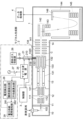
- FIG. 1 is a schematic diagram showing the configuration of a mass spectrometer according to an embodiment of the present invention
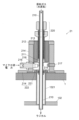
- FIG. 2 is a configuration diagram of a main part of a radical production device in the mass spectrometer of the present embodiment.
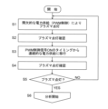
- 4 is a control flowchart at the start of analysis in the mass spectrometer of the present embodiment.
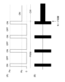
- 3A and 3B are diagrams showing the concept of a control signal waveform and an example of a microwave waveform for generating plasma in the mass spectrometer of the present embodiment.
- 5 is a diagram showing the relationship between the instantaneous value of current consumption and whether the power supply is cut off or not in the mass spectrometer of the present embodiment.
- FIG. FIG. 2 is a diagram showing an example of a schematic circuit configuration of a power supply abnormality detection unit in the mass spectrometer of the present embodiment.
- an ion analyzer according to the present invention will be described with reference to the accompanying drawings. Below, a mass spectrometer will be described as one embodiment of an ion analyzer, but it will be clear from the following description that an ion mobility analyzer or an ion mobility-mass analyzer may also be used.
- FIG. 1 is a schematic diagram of the mass spectrometer of this embodiment.
- This mass spectrometer is a quadrupole time-of-flight (Q-TOF) mass spectrometer equipped with an atmospheric pressure ion source.
- Q-TOF time-of-flight
- this mass spectrometer has an ionization chamber 10 and a vacuum chamber 1.
- the inside of the ionization chamber 10 is at approximately atmospheric pressure.
- the inside of the vacuum chamber 1 is divided into multiple compartments (four compartments in this embodiment), which are, starting from the side closest to the ionization chamber 10, a first intermediate vacuum chamber 11, a second intermediate vacuum chamber 12, a first analysis chamber 13, and a second analysis chamber 14.
- Each of these chambers is evacuated to a vacuum by a vacuum pump (rotary pump and/or turbomolecular pump) (not shown), and the degree of vacuum increases from the ionization chamber 10 to the second analysis chamber 14, forming a multi-stage differential pumping system.
- the ionization chamber 10 is equipped with an electrospray ionization (ESI) probe 101 that applies an electric charge to a liquid sample and sprays it.
- EI electrospray ionization
- the ionization chamber 10 and the first intermediate vacuum chamber 11 are connected through a thin-diameter desolvation tube 102.
- the first intermediate vacuum chamber 11 and the second intermediate vacuum chamber 12 are separated by a skimmer 112 with a small hole at the top.
- the first intermediate vacuum chamber 11 and the second intermediate vacuum chamber 12 are equipped with ion guides 111 and 121, respectively.
- a quadrupole mass filter 131 that separates ions according to m/z, a collision cell 132 equipped with a multipole ion guide 133 inside, and an ion transport electrode 134 for transporting ions are arranged along the ion optical axis C.
- the quadrupole mass filter 131 and the multipole ion guide 133 are each composed of multiple rod electrodes, and the ion transport electrode 134 is composed of multiple ring-shaped electrodes.
- An opening 1320 is formed in the wall of the collision cell 132, and a cylindrical tube connection member 1321 is provided so that one end surrounds this opening 1320.
- a quartz tube 210 extending from the radical generation unit 2 is inserted inside this tube connection member 1321, and the end of the quartz tube 210 protrudes into the collision cell 132 through the opening 1320.
- ions are dissociated by radical species supplied from the radical generation unit 2.
- the collision cell 132 can be supplied with a gas for causing collision induced dissociation (CID) in the collision cell 132, in addition to the radical generation unit 2.
- CID collision induced dissociation
- the second analysis chamber 14 is equipped with an ion transport electrode 141 for transporting ions incident from the first analysis chamber 13, an orthogonal acceleration section 142 including a pair of electrodes arranged opposite each other across the ion optical axis C, an acceleration electrode 143, a flight tube 144 that forms a flight space inside, a reflectron electrode 145 that forms a return trajectory of the ions in the flight space, and an ion detector 146 that detects ions.
- the ion detector 146 is, for example, a multi-channel plate type detector.
- the detection signal from the ion detector 146 is input to the data processing section 4.
- the control section 3 controls the radical generation section 2, the data processing section 4, and also power supplies that apply voltages and the like to each section.
- a typical analytical operation in the mass spectrometer having the above configuration, which is performed under the control of the control unit 3, is as follows.
- the ESI probe 101 sprays a liquid sample supplied from, for example, a column outlet of a liquid chromatograph into the ionization chamber 10 while imparting an electric charge to the liquid sample, thereby ionizing compounds in the liquid sample.
- the generated ions are sent to the first intermediate vacuum chamber 11 through the desolvation tube 102.
- the ions that enter the first intermediate vacuum chamber 11 are sent to the first analysis chamber 13 via the ion guide 111, the small hole of the skimmer 112, and the ion guide 121, and are introduced into the quadrupole mass filter 131.
- Ions introduced into the orthogonal acceleration section 142 along the ion optical axis C are ejected in a direction substantially orthogonal to the ion optical axis C at a predetermined timing.
- the ejected ions are accelerated by the acceleration electrode 143 and introduced into the flight space in the flight tube 144.
- the ions fly in a return flight due to the electric field formed by the reflectron electrode 145, and finally reach the ion detector 146.
- the ion detector 146 outputs a detection signal according to the amount of incident ions to the data processing section 4.
- the radical generating unit 2 includes a plasma generating unit 21.
- the plasma generating unit 21 generates plasma based on a raw material gas such as water vapor supplied from a raw material gas supply source 26, and supplies radicals generated in the plasma to a collision cell 132.
- a microwave power source 25 supplies high-frequency (microwave) power for generating plasma to the plasma generating unit 21.
- the amount of raw material gas supplied from the raw material gas supply source 26 to the plasma generating unit 21 is adjusted by a valve 20 provided in a flow path connecting the raw material gas supply source 26 and a quartz tube 210.
- FIG. 2 is a vertical cross-sectional view of the essential parts of the radical generating section 2, focusing on the plasma generating section 21.
- the plasma generating unit 21 includes a long quartz tube 210, a helical antenna 211 which is a strip-shaped conductor wound in a spiral shape around the outer periphery of a part of the quartz tube 210, an outer conductor part 212 which is coaxial with the quartz tube 210 and has a cylindrical opening whose inner diameter is one size larger than the outer diameter of the quartz tube 210, a permanent magnet 213 embedded in the outer conductor part 212, a casing 214 which holds the outer conductor part 212, and a permanent magnet 215 which is disposed at the bottom of the casing 214.
- the casing 214 is provided with a microwave supply connector 216, an ultraviolet light source 217, and a photodetector 218.
- the ultraviolet light source 217 irradiates the quartz tube 210 with deep ultraviolet light, electrons are emitted from the wall surface of the quartz tube 210, and the electrons induce ignition of plasma.
- the quartz tube 210 is a raw material introduction tube into which raw material gas is introduced from the raw material gas supply source 26, and its interior serves as a generation chamber and a radical flow path.
- the microwave supply connector 216 is a coaxial connector, and is connected to the microwave power source 25 via a coaxial cable.
- the conductive wire of the microwave supply connector 216 is connected to one end (the lower end in FIG. 2) of the helical antenna 211.
- the outer conductor 212 is grounded.
- a part of the helical antenna 211 and the outer conductor 212 are electrically connected via the resonator adjustment mechanism 220, and the helical antenna 211 is grounded at the connection position.
- the helical antenna 211, the outer conductor 212, the resonator adjustment mechanism 220, etc. constitute an electron cyclotron resonance resonator.
- the resonator adjustment mechanism 220 is used to adjust the resonator, and is described in, for example, Patent Document 3.
- This plasma generating unit 21 is of a type known as an ECR-LICP type, which uses local inductively coupled discharge and electron cyclotron resonance to generate and maintain plasma.
- a roughly disk-shaped magnet holder 221 is attached to the bottom surface of the casing 214.
- the casing 214 and the magnet holder 221 function as a holding member 222 that holds the quartz tube 210.
- An opening is formed in the center of the magnet holder 221 through which the quartz tube 210 is inserted.
- the plasma generating unit 21 is attached to the outer surface of the vacuum chamber 1 so as to cover the opening formed in the vacuum chamber 1, and the quartz tube 210 held by the holding member 222 is inserted into the inside of the tube connecting member 1321 that connects the collision cell 132 and the vacuum chamber 1, and reaches the inside of the collision cell 132. Since the inside of the quartz tube 210 is connected to the inside of the collision cell 132, the inside of the quartz tube 210 is also in a vacuum state when no raw material gas is supplied to the quartz tube 210.
- FIG. 3 is a control flowchart for this operation.
- FIG. 4 is a diagram showing the concept of a control signal waveform for plasma generation and an example of a microwave waveform.
- FIG. 4(A) is a pseudo waveform diagram showing the time passage on the horizontal axis and the magnitude of the supplied microwave power on the vertical axis
- FIG. 4(B) is a diagram showing the change over time in the voltage applied to the helical antenna 211.
- the control unit 3 opens the valve 20 and flows a predetermined flow rate of raw material gas into the quartz tube 210.
- the raw material gas is assumed to be water vapor.
- the control unit 3 inputs a pulse width modulation (PWM) control signal with a predetermined duty ratio (proportion of the on period in one period) to the microwave power supply 25.
- PWM pulse width modulation
- the microwave power supply 25 outputs microwaves with a predetermined frequency and a predetermined output during the period when the PWM control signal is on (period when the crest value is Pa or Pb in FIG.
- the PWM control circuit and microwave power supply 25 included in the control unit 3 attempt to light the plasma by PWM drive (step S1).
- the frequency of the PWM control signal is 100 Hz, and the duty ratio is usually in the range of 10 to 20%, but is set to 10% here.
- the microwave frequency is 2.5 GHz, and the microwave output power is 250 W. This output power is sufficient to light the plasma.
- these values are merely examples and can be changed as appropriate.
- the PWM control signal is on, that is, when microwave power is being supplied to the generation chamber inside the quartz tube 210, the water vapor, which is the raw material gas, is usually ionized and plasma is lit.
- the PWM control signal is off, that is, when the supply of microwave power is stopped, the plasma is turned off. Therefore, as the PWM control signal is switched on and off, the plasma repeatedly turns on and off.
- the PWM control signal changes from off to on and microwave power is being supplied, there may be cases where the plasma does not turn on.
- the photodetector 218 arranged in the generation chamber detects light in a wavelength band that includes the wavelength of the light emitted from the plasma. It is preferable that the photodetector 218 has no sensitivity to the wavelength of light emitted from the ultraviolet light source 217 so as not to detect this light. Therefore, here, a photodiode that has sensitivity in the visible light range (no sensitivity or low sensitivity to the ultraviolet light range) is used as the photodetector 218. This makes it possible to effectively detect the light emitted by the plasma without being affected by the light emitted from the ultraviolet light source 217.
- the control unit 3 monitors the output signal from the photodetector 218 a predetermined time (e.g., 1 to 10 seconds) after the plasma lighting starts (the point at which the PWM control signal starts to be switched on and off), and determines whether the plasma is lit or not based on the signal value.
- a predetermined time e.g. 1 to 10 seconds
- the detection signal by the photodetector 218 also changes accordingly, but here, it is not necessary to detect the change in light intensity synchronized with the cycle (e.g., 100 Hz) of the PWM control signal. This is because, as described above, even when the PWM control signal is on, the plasma is not necessarily turned on, and although the probability is low, the plasma may remain off.
- the detection signal by the photodetector 218 may be input to a smoothing circuit or integration circuit with an appropriate time constant to obtain a signal obtained by smoothing or integrating the detection signal over a predetermined time, and the signal may be compared with a predetermined threshold value to determine whether the plasma is turned on overall.
- a smoothing circuit or integration circuit with an appropriate time constant to obtain a signal obtained by smoothing or integrating the detection signal over a predetermined time, and the signal may be compared with a predetermined threshold value to determine whether the plasma is turned on overall.
- processing can be performed digitally, or other circuits can be used to determine whether the plasma is turned on overall during the PWM control period (the period indicated by "PWM" in FIG. 4).
- the control unit 3 waits in step S2 until it is determined that the plasma is in an lit state, and when it is in an lit state, it proceeds to step S3. If a predetermined upper limit time (for example, an appropriate time of 10 seconds or more) has passed without the plasma being in an lit state, there is a high possibility that some kind of abnormality exists, such as an abnormality in the microwave power supply path or an improper supply of raw material gas, and measures can be taken, such as reporting the abnormality.
- a predetermined upper limit time for example, an appropriate time of 10 seconds or more
- step S3 the control unit 3 controls the microwave power supply 25 to continuously supply microwave power from the timing when the PWM control signal is in the on period. That is, the control mode is switched from the intermittent mode, which supplies microwave power intermittently, to the continuous mode, which supplies microwave power continuously.
- the continuous mode the instantaneous output power is reduced compared to the instantaneous output power in the intermittent mode. This is because if the instantaneous large output power is continuously supplied as in the intermittent mode, the helical antenna 211 will generate too much heat, and the quartz tube 210 and other parts in contact with the helical antenna 211 may become too hot and be damaged by thermal expansion.
- plasma requires a large amount of power to start turning on from a completely off state, but once the plasma is turned on, it will remain on even if the power supplied is reduced. Therefore, if the mode is switched to continuous mode while the PWM control signal is on and the plasma is on, the previous on state will generally continue.
- the plasma is not necessarily on even during the on period of the PWM control signal in intermittent mode, and control to switch to continuous mode may be performed when the PWM control signal is on and the plasma is not on. In that case, the plasma will remain off even after switching from intermittent mode to continuous mode. Also, even if control to switch to continuous mode is performed while the PWM control signal is on and the plasma is on, the plasma may be turned off when switching to continuous mode.
- the control unit 3 monitors the output signal from the photodetector 218 and checks whether the plasma is turned on or not based on the signal value (step S4). If it is determined that the plasma is turned on (YES in step S5), the process proceeds from step S5 to S6, and MS/MS analysis using radical attachment dissociation is started. On the other hand, if it is determined that the plasma is not turned on after switching to continuous mode (NO in step S5), the process returns from step S5 to S1, and the control unit 3 retries controlling the start of plasma lighting.
- the instantaneous output power is lower than in intermittent mode, but the plasma is not repeatedly turned on and off, so the plasma state tends to be stable. Therefore, in the mass spectrometer of this embodiment, a plasma is stably formed in the generation chamber, and MS/MS analysis can be performed in a state in which the radicals generated in the plasma are stably supplied to the collision cell 132. This allows stable and good detection of product ions generated by radical attachment dissociation.
- the helical antenna 211 when microwave power is supplied to the helical antenna 211, the helical antenna 211 generates heat, and the temperature of components such as the quartz tube 210 rises.
- the heat from the radical generation section 2 is also transmitted to the mass separation section through the quartz tube 210, etc., and may affect mass analysis performance.
- the heat causes the flight tube 144 to expand or the electrode spacing of the reflectron electrode 145 to change, adverse effects such as a change in the flight time of ions with the same m/z value and an increase in mass error are possible.
- it is not possible to completely suppress heat generation in either the intermittent mode or the continuous mode in order to suppress the effect on mass analysis performance, it is desirable to roughly match the amount of heat generated in the intermittent mode and the continuous mode. Therefore, it is advisable to roughly match the power supplied per unit time, that is, the average power, in the intermittent mode and the continuous mode.
- the instantaneous output power in the intermittent mode is Pa
- the instantaneous output power in the continuous mode is Pb, Pa ⁇ D ⁇ Pb ...
- the control unit 3 supplies an appropriate PWM control signal to the microwave power supply 25 as described above, and the microwave power supply 25 appropriately turns the microwave output on/off and adjusts its output power in response to this control signal, the radical generation unit 2 operates well.
- the PWM control circuit or microwave power supply 25 included in the control unit 3 excessive output power may be supplied to the helical antenna 211, causing the helical antenna 211 to heat abnormally. This is the case, for example, when a malfunction occurs in the PWM control circuit and the PWM control signal is continuously on with the instantaneous output power set to Pa.
- the mass spectrometer of this embodiment has a kind of circuit protection function that prevents excessive power from being supplied to the plasma generation unit 21, specifically, prevents an excessive current from being supplied to the helical antenna 211, even if an operational malfunction or malfunction occurs in the PWM control circuit or microwave power supply 25.
- the radical generator 2 includes a current detector 28 and a power supply anomaly detector 29 as the circuit protection function.
- the current detector 28 detects the current consumption of the microwave power source 25, and includes an instantaneous value detector 281 and an average value calculator 282.
- the instantaneous value detector 281 detects the instantaneous value of the current consumption that changes from moment to moment in the microwave power source 25.
- the average value calculator 282 calculates the average value of the current consumption per unit time in real time.
- the average value calculator 282 first outputs the presence or absence of current consumption in real time as a binary signal of "H” and "L", and by setting the "H" level to a voltage value of +5V and the "L” level to a voltage value of 0V, and smoothing the fluctuation of the voltage value within a unit time, can obtain a value corresponding to the average value of the current consumption.
- the configuration of the average value calculator 282 is not limited to this.
- the power supply abnormality detection unit 29 judges whether or not there is an abnormality in the microwave power supplied from the microwave power supply 25 to the plasma generation unit 21 based on the signal from the current detection unit 28. If the power supply abnormality detection unit 29 judges there is an abnormality, it disconnects the relay 27 inserted in the power line that supplies power to operate the microwave power supply 25, and cuts off the power supply to the microwave power supply 25.
- FIG. 5 is a diagram showing the relationship between the instantaneous value of current consumption and whether the power supply is cut off or not
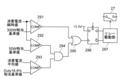
- FIG. 6 is a diagram showing an example of a schematic circuit configuration of the power supply abnormality detection unit 29.
- the instantaneous values of the current consumption detected by the instantaneous value detection unit 281 are both input to one input terminal of the first comparator 291 and the second comparator 292.
- the instantaneous value of the current consumption corresponding to an output power of 300 W is input as a reference value to the other input terminal of the first comparator 291.
- the instantaneous value of the current consumption corresponding to an output power of 50 W is input as a reference value to the other input terminal of the second comparator 292.
- the average value of the current consumption calculated by the average value calculation unit 282 is input to one input terminal of the third comparator 293, and the average value of the current consumption corresponding to a duty ratio of the PWM control signal of 16.6% is input as a reference value to the other input terminal.
- the output of the second comparator 292 and the output of the third comparator 293 are input to an AND operation gate 294, and the output of the AND operation gate 294 and the output of the first comparator 291 are input to an OR operation gate 295.
- the output of the OR gate 295 is input as a clock to a latch circuit 296 which receives as its data a predetermined voltage value (3.3 V in this example) corresponding to the "H" logic.
- the output of the latch circuit 296 is input to a relay driver 297 which turns on/off the relay 27.
- the reason why the average value of the current consumption corresponding to the duty ratio of the PWM control signal being 16.6% is used as the reference value input to the third comparator 293 is that since the duty ratio in intermittent mode is 10%, by setting it at 16.6%, it is possible to distinguish between intermittent mode and continuous mode even when fluctuations in the duty ratio are taken into account. That is, the third comparator 293 outputs "L” if the current consumption is in a state corresponding to normal intermittent mode, and outputs "H” if it is in any other state (duty ratio is 16.6% or more).
- the first comparator 291 outputs "H” if the instantaneous value of the current consumption is equal to or greater than the output power of 300 W, and the second comparator 292 outputs "H” if the instantaneous value of the current consumption is equal to or greater than the output power of 50 W.
- the AND gate 294 outputs "H” if the duty ratio is 16.6% or more and the instantaneous value of the current consumption is equal to or greater than the output power of 50 W.
- the OR gate 295 outputs "H” when the instantaneous value of the current consumption is equal to or greater than the output power of 300 W, or when the duty ratio is 16.6% or more and the instantaneous value of the current consumption is equal to or greater than the output power of 50 W.
- the latch circuit 296 is initially reset, for example, at the start of the plasma generation operation, and outputs "H” when the output of the OR gate 295 becomes “H” under the above-mentioned conditions (output Q becomes "H” and output Q bar becomes “L”).
- the relay drive unit 297 cuts off the relay 27, thereby cutting off the power supply to the microwave power source 25.
- the power supply abnormality detection unit 29 Since the power supply abnormality detection unit 29 operates as described above, as shown in FIG. 5, if the instantaneous value of the current consumption is equal to or exceeds an output power of 300 W, the power supply to the microwave power supply 25 is cut off regardless of the duty ratio. When the instantaneous value of the current consumption is equal to or exceeds an output power of 300 W, there is a high possibility that there is an abnormality in the microwave power supply 25. Therefore, by cutting off the power supply to the microwave power supply 25, it is possible to prevent excessive current from being supplied to the helical antenna 211, and to avoid secondary failures or fatal damage.
- the instantaneous value of the current consumption corresponds to an output power range of 50W or more and less than 300W
- the duty ratio is 16.6% or more
- the average output power from the microwave power supply 25 may exceed 50W. Therefore, by cutting off the power supply to the microwave power supply 25, it is possible to prevent excessive current from being supplied to the helical antenna 211.
- the instantaneous value of the current consumption corresponds to an output power range of 50W or more and less than 300W
- the duty ratio is less than 16.6%
- the average output power from the microwave power supply 25 will be within 50W. Therefore, the power supply to the microwave power supply 25 continues.
- the instantaneous value of the current consumption is less than the output power of 50W
- the power supply to the microwave power supply 25 continues regardless of the duty ratio.
- the mass spectrometer of this embodiment prevents excessive microwave power from being supplied to the plasma generation unit 21 due to an abnormality or malfunction of the microwave power supply 25 included in the radical generation unit 2 or the control unit 3 that controls the microwave power supply 25, and can prevent serious problems such as damage to the parts and members included in the plasma generation unit 21 and even to the parts and members around them.
- the power supply abnormality detection unit 29 can have a configuration other than that shown in FIG. 6 in order to realize the circuit protection function described above. It is also clear that the values of the output power and duty ratio for determining that an abnormality has occurred can be appropriately determined depending on the configuration, structure, control method, etc. of the device.
- the ion analyzer according to the present invention is applied to a Q-TOF mass analyzer, but it is clear that the present invention is not limited to Q-TOF types.
- the present invention can also be applied to triple quadrupole mass analyzers, ion trap mass analyzers, ion trap time-of-flight mass analyzers, and the like.
- the present invention can also be applied to devices in general that dissociate ions using radical species generated in plasma and analyze the product ions generated by the dissociation.
- the present invention can also be applied to ion mobility analyzers that separate and detect ions according to ion mobility, and ion mobility-mass analyzers that separate ions using both ion mobility and m/z.
- the configuration of the mass spectrometer described above, particularly the configuration of the radical generation unit 2 that generates radical species, is merely one example, and it goes without saying that any configuration that can generate radical species using plasma can be modified as appropriate.
- the radical species referred to here include hydroxyl radicals, oxygen radicals, nitrogen radicals, hydrogen radicals, and the like that are generally used in radical attachment and dissociation, as well as various molecules and atoms that are in an excited state or in a metastable state when energy is applied.
- One aspect of the ion analyzer according to the present invention is an ion analyzer that introduces radical species generated in plasma into a reaction chamber, and brings the radical species into contact with ions derived from a sample in the reaction chamber to dissociate the ions, a generation chamber into which a source gas is introduced; a power supply unit that supplies high frequency power for generating plasma inside the generation chamber; A control unit that controls the power supply unit to adjust the high frequency power supplied to the generation chamber, and switches between an intermittent mode in which the high frequency power is intermittently supplied and a continuous mode in which the high frequency power having a lower output power than that of the high frequency power supplied in the intermittent mode is continuously supplied; a current detection unit that detects a current consumption of the power supply unit; an abnormality response unit that cuts off power to be supplied to the power supply unit based on the detected value of the current consumption; Equipped with.
- the abnormality response unit cuts off the power supply by turning off a relay installed on the line that supplies power to the power supply unit.
- the power supplied from the high-frequency power supply unit to the generation chamber can be cut off. This makes it possible to avoid abnormal heating of the components of the generation unit due to excessive power supply and prevent secondary failures from occurring.
- the current detection unit includes an instantaneous value detection unit that detects the instantaneous value of the current consumption, and the abnormality response unit can determine whether or not to cut off power based on the detected instantaneous value.
- an abnormality in the power for generating plasma supplied to the generation chamber is detected by the instantaneous value of the current consumption, and if an abnormality is suspected, the power that operates the power supply unit is cut off.
- the power supplied to the generation chamber can be quickly stopped, and abnormal heating of, for example, a helical antenna for generating plasma can be more reliably prevented.
- the current detection unit further includes a corresponding value calculation unit that determines, based on the current consumption, a value corresponding to a duty ratio, which is the ratio of the period during which the power supplied from the power supply unit to the generation chamber is on/off, and the abnormality response unit can change the reference value for determining the instantaneous value according to the value corresponding to the duty ratio.
- high frequency power may be supplied to the generation chamber intermittently (intermittent mode) or continuously (continuous mode). Even if the instantaneous value of current consumption is the same, when high frequency power is supplied to the generation chamber continuously, the average power per unit time is greater than when it is supplied to the generation chamber intermittently, and there is a high possibility that the helical antenna, etc., will be abnormally heated.
- the corresponding value calculation unit can digitize the presence or absence of current consumption and smooth the digitized signal to determine the value corresponding to the duty ratio.
- the ion analyzer described in paragraph 4 can accurately determine the value corresponding to the duty ratio using a simple and inexpensive circuit.
- Vacuum chamber 1000 Opening 10: Ionization chamber 101: ESI probe 102: Desolvation tube 11: First intermediate vacuum chamber 111: Ion guide 112: Skimmer 12: Second intermediate vacuum chamber 121: Ion guide 13: First analysis chamber 131: Quadrupole mass filter 132: Collision cell 1320: Opening 1321: Tube connection member 133: Multipole ion guide 134: Ion transport electrode 14: Second analysis chamber 141: Ion transport electrode 142: Orthogonal acceleration section 143: Acceleration electrode 144: Flight tube 145: Reflectron electrode 146: Ion detector 2: Radical generation section 20: Valve 21: Plasma generation section 210: Quartz tube 211: Helical antenna 212: Outer conductor section 213, 215: Permanent magnet 214: Casing 216: Microwave supply connector 217: Ultraviolet light source 218: Photodetector 220: Resonator adjustment mechanism 221: Magnet holder 222: Holding member 25: Microwave power source 26: Raw material gas
Landscapes
- Physics & Mathematics (AREA)
- Chemical & Material Sciences (AREA)
- Analytical Chemistry (AREA)
- Engineering & Computer Science (AREA)
- Plasma & Fusion (AREA)
- Electromagnetism (AREA)
- Spectroscopy & Molecular Physics (AREA)
- Other Investigation Or Analysis Of Materials By Electrical Means (AREA)
Abstract
Selon un mode de réalisation, la présente invention porte sur un dispositif d'analyse d'ions qui introduit des espèces radicalaires, générées dans le plasma, dans une chambre de réaction (132), et amène les espèces radicalaires en contact avec des ions dérivés d'un échantillon dans la chambre de réaction et conduit les ions à se dissocier. Le dispositif d'analyse d'ions comprend : une chambre de génération (210) dans laquelle un gaz de matière première est introduit ; une unité d'alimentation (25) pour fournir une puissance haute fréquence afin de provoquer la production d'un plasma à l'intérieur de la chambre de génération ; une unité de commande (3) pour commander l'unité d'alimentation électrique afin d'ajuster la puissance haute fréquence fournie à la chambre de génération, l'unité de commande commutant entre un mode intermittent pour fournir par intermittence la puissance haute fréquence et un mode continu pour fournir en continu une puissance haute fréquence qui est une puissance de sortie inférieure à la puissance haute fréquence fournie dans le mode intermittent ; une unité de détection de courant (28) pour détecter un courant consommé de l'unité d'alimentation électrique ; et une unité de réponse d'anomalie (29, 27) pour arrêter la puissance fournie à l'unité d'alimentation électrique sur la base de la valeur du courant consommé qui a été détectée.
Priority Applications (2)
| Application Number | Priority Date | Filing Date | Title |
|---|---|---|---|
| PCT/JP2023/030180 WO2025041271A1 (fr) | 2023-08-22 | 2023-08-22 | Dispositif d'analyse d'ions |
| JP2025541222A JPWO2025041271A1 (fr) | 2023-08-22 | 2023-08-22 |
Applications Claiming Priority (1)
| Application Number | Priority Date | Filing Date | Title |
|---|---|---|---|
| PCT/JP2023/030180 WO2025041271A1 (fr) | 2023-08-22 | 2023-08-22 | Dispositif d'analyse d'ions |
Publications (1)
| Publication Number | Publication Date |
|---|---|
| WO2025041271A1 true WO2025041271A1 (fr) | 2025-02-27 |
Family
ID=94731974
Family Applications (1)
| Application Number | Title | Priority Date | Filing Date |
|---|---|---|---|
| PCT/JP2023/030180 Pending WO2025041271A1 (fr) | 2023-08-22 | 2023-08-22 | Dispositif d'analyse d'ions |
Country Status (2)
| Country | Link |
|---|---|
| JP (1) | JPWO2025041271A1 (fr) |
| WO (1) | WO2025041271A1 (fr) |
Citations (4)
| Publication number | Priority date | Publication date | Assignee | Title |
|---|---|---|---|---|
| JPH06349594A (ja) * | 1993-06-07 | 1994-12-22 | Mitsubishi Electric Corp | プラズマ発生装置 |
| KR20100098097A (ko) * | 2009-02-27 | 2010-09-06 | 주식회사 뉴파워 프라즈마 | 플라즈마 점화와 전력 제어를 위한 방법 및 장치 |
| JP2016178446A (ja) * | 2015-03-19 | 2016-10-06 | 株式会社日立国際電気 | 高周波電源装置 |
| WO2023013161A1 (fr) * | 2021-08-02 | 2023-02-09 | 株式会社島津製作所 | Dispositif de spectrométrie de masse et procédé de spectrométrie de masse |
-
2023
- 2023-08-22 WO PCT/JP2023/030180 patent/WO2025041271A1/fr active Pending
- 2023-08-22 JP JP2025541222A patent/JPWO2025041271A1/ja active Pending
Patent Citations (4)
| Publication number | Priority date | Publication date | Assignee | Title |
|---|---|---|---|---|
| JPH06349594A (ja) * | 1993-06-07 | 1994-12-22 | Mitsubishi Electric Corp | プラズマ発生装置 |
| KR20100098097A (ko) * | 2009-02-27 | 2010-09-06 | 주식회사 뉴파워 프라즈마 | 플라즈마 점화와 전력 제어를 위한 방법 및 장치 |
| JP2016178446A (ja) * | 2015-03-19 | 2016-10-06 | 株式会社日立国際電気 | 高周波電源装置 |
| WO2023013161A1 (fr) * | 2021-08-02 | 2023-02-09 | 株式会社島津製作所 | Dispositif de spectrométrie de masse et procédé de spectrométrie de masse |
Also Published As
| Publication number | Publication date |
|---|---|
| JPWO2025041271A1 (fr) | 2025-02-27 |
Similar Documents
| Publication | Publication Date | Title |
|---|---|---|
| EP2610892B1 (fr) | Spectromètre de masse et spectrométrie de masse | |
| JP5330823B2 (ja) | プラズマ発生装置およびプラズマ発生方法 | |
| EP3234978B1 (fr) | Dispositif d'ionisation et spectromètre de masse en étant équipé | |
| US11393669B2 (en) | Mass spectrometer | |
| US9589775B2 (en) | Plasma cleaning for mass spectrometers | |
| US11848187B2 (en) | Mass spectrometer | |
| JP4793440B2 (ja) | 質量分析装置 | |
| TWI875744B (zh) | 包含離子化裝置的質譜儀 | |
| US20240347328A1 (en) | Mass Spectrometer and Mass Spectrometry Method | |
| US20240242954A1 (en) | Mass Spectrometer and Mass Spectrometry Method | |
| WO2025041271A1 (fr) | Dispositif d'analyse d'ions | |
| WO2025041231A1 (fr) | Dispositif d'analyse d'ions et procédé d'analyse d'ions | |
| EP3540757B1 (fr) | Appareil et procédé d'analyse de masse | |
| US20250132142A1 (en) | Ion Analyzer and Ion Analyzing Method | |
| JP4692627B2 (ja) | 質量分析装置 | |
| JP2025094998A (ja) | イオン分析装置及びイオン分析方法 | |
| JP7735882B2 (ja) | 質量分析装置及び質量分析装置の調整方法 | |
| US20250130201A1 (en) | Ion Analyzer and Ion Analyzing Method | |
| JP7780410B2 (ja) | イオン源、質量分析計、及び、イオン源製造方法 | |
| JP2024057924A (ja) | 質量分析装置 | |
| JP2025029786A (ja) | イオン分析装置 | |
| WO2024171416A1 (fr) | Dispositif de spectrométrie de masse et procédé de spectrométrie de masse | |
| JPH06342640A (ja) | 高周波誘導結合プラズマ質量分析装置 |
Legal Events
| Date | Code | Title | Description |
|---|---|---|---|
| 121 | Ep: the epo has been informed by wipo that ep was designated in this application |
Ref document number: 23949732 Country of ref document: EP Kind code of ref document: A1 |
|
| ENP | Entry into the national phase |
Ref document number: 2025541222 Country of ref document: JP Kind code of ref document: A |
|
| NENP | Non-entry into the national phase |
Ref country code: DE |