WO2025041271A1 - イオン分析装置 - Google Patents
イオン分析装置 Download PDFInfo
- Publication number
- WO2025041271A1 WO2025041271A1 PCT/JP2023/030180 JP2023030180W WO2025041271A1 WO 2025041271 A1 WO2025041271 A1 WO 2025041271A1 JP 2023030180 W JP2023030180 W JP 2023030180W WO 2025041271 A1 WO2025041271 A1 WO 2025041271A1
- Authority
- WO
- WIPO (PCT)
- Prior art keywords
- power supply
- unit
- power
- plasma
- supplied
- Prior art date
- Legal status (The legal status is an assumption and is not a legal conclusion. Google has not performed a legal analysis and makes no representation as to the accuracy of the status listed.)
- Pending
Links
Images
Classifications
-
- H—ELECTRICITY
- H01—ELECTRIC ELEMENTS
- H01J—ELECTRIC DISCHARGE TUBES OR DISCHARGE LAMPS
- H01J49/00—Particle spectrometers or separator tubes
-
- H—ELECTRICITY
- H01—ELECTRIC ELEMENTS
- H01J—ELECTRIC DISCHARGE TUBES OR DISCHARGE LAMPS
- H01J49/00—Particle spectrometers or separator tubes
- H01J49/02—Details
-
- H—ELECTRICITY
- H05—ELECTRIC TECHNIQUES NOT OTHERWISE PROVIDED FOR
- H05H—PLASMA TECHNIQUE; PRODUCTION OF ACCELERATED ELECTRICALLY-CHARGED PARTICLES OR OF NEUTRONS; PRODUCTION OR ACCELERATION OF NEUTRAL MOLECULAR OR ATOMIC BEAMS
- H05H1/00—Generating plasma; Handling plasma
- H05H1/24—Generating plasma
- H05H1/26—Plasma torches
- H05H1/30—Plasma torches using applied electromagnetic fields, e.g. high frequency or microwave energy
Definitions
- the present invention relates to an ion analyzer that analyzes ions derived from a target component contained in a sample.
- mass spectrometry In order to identify sample components such as polymer compounds contained in a sample and analyze their structure, mass spectrometry is widely used, in which ions with a specific m/z (mass-to-charge ratio) are selected from ions derived from the sample components, and the ions are dissociated to generate various product ions that are separated and detected according to m/z.
- ions with a specific m/z mass-to-charge ratio
- Patent Document 3 discloses an example of a radical generation device for generating radicals used in the radical-induced dissociation method.
- This radical generation device has a quartz tube and a helical antenna consisting of a strip-shaped conductor wound around its outer circumference.
- a raw material gas such as water vapor is introduced into the quartz tube, and high-frequency power is supplied to the helical antenna to generate plasma inside the quartz tube, and radicals are generated in the plasma.
- a magnet that generates a strong magnetic field is placed on the outside of the quartz tube, and electron cyclotron resonance using this magnetic field is used to increase the density of the plasma inside the quartz tube and stabilize the generation of the plasma.
- This radical generation device uses localized inductive discharge and electron cyclotron resonance to generate and maintain the plasma, and is therefore sometimes called the ECR-LICP (Electron Cyclotron Resonance - Localized Inductively Coupled Plasma) type.
- the above-mentioned radical generation device requires the supply of high-frequency power to generate plasma, but if a large amount of high-frequency power is continuously supplied, the helical antenna will become hot, raising concerns that components such as the quartz tube may be damaged by thermal expansion.
- the device described in Patent Document 4 uses pulse-width modulation (PWM) control to intermittently supply high-frequency power, thereby preventing excessive temperature rise in the helical antenna and other components while still supplying the power required to generate plasma.
- PWM pulse-width modulation
- fuses are inserted or a combination of a temperature sensor and a relay is used to prevent overcurrent from flowing in electronic circuits due to malfunctions, etc.
- a strong magnetic field is generated in the device and its surroundings during operation, which can cause unwanted currents to flow in circuit elements such as fuses and temperature sensors due to electromagnetic induction, causing the elements to not function properly. For this reason, the overcurrent prevention measures used in typical devices are not effective in the above radical generation device.
- the present invention has been made to solve these problems, and its main objective is to provide an ion analyzer that can effectively prevent excessive high-frequency power from being supplied to the plasma generation section, thereby avoiding the occurrence of secondary failures, even if a failure occurs in the high-frequency power supply section for plasma generation or in the control system circuitry.
- One aspect of the ion analyzer according to the present invention is an ion analyzer that introduces radical species generated in plasma into a reaction chamber, and brings the radical species into contact with ions derived from a sample in the reaction chamber to dissociate the ions, a generation chamber into which a source gas is introduced; a power supply unit that supplies high frequency power for generating plasma inside the generation chamber; A control unit that controls the power supply unit to adjust the high frequency power supplied to the generation chamber, and switches between an intermittent mode in which the high frequency power is intermittently supplied and a continuous mode in which the high frequency power having a lower output power than that of the high frequency power supplied in the intermittent mode is continuously supplied; a current detection unit that detects a current consumption of the power supply unit; an abnormality response unit that cuts off power to be supplied to the power supply unit based on the detected value of the current consumption; Equipped with.
- the ion analysis device of the present invention can cut off the power supplied from the high frequency power supply unit to the generation chamber when the current consumption in the high frequency power supply unit increases abnormally due to a failure in the high frequency power supply unit that supplies power to the plasma or in the control circuit that controls the operation of the power supply unit. This can avoid abnormal heating of the components in the generation unit due to an excessive power supply, and prevent the occurrence of secondary failures.
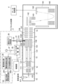
- FIG. 1 is a schematic diagram showing the configuration of a mass spectrometer according to an embodiment of the present invention
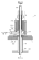
- FIG. 2 is a configuration diagram of a main part of a radical production device in the mass spectrometer of the present embodiment.
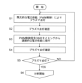
- 4 is a control flowchart at the start of analysis in the mass spectrometer of the present embodiment.
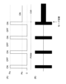
- 3A and 3B are diagrams showing the concept of a control signal waveform and an example of a microwave waveform for generating plasma in the mass spectrometer of the present embodiment.
- 5 is a diagram showing the relationship between the instantaneous value of current consumption and whether the power supply is cut off or not in the mass spectrometer of the present embodiment.
- FIG. FIG. 2 is a diagram showing an example of a schematic circuit configuration of a power supply abnormality detection unit in the mass spectrometer of the present embodiment.
- an ion analyzer according to the present invention will be described with reference to the accompanying drawings. Below, a mass spectrometer will be described as one embodiment of an ion analyzer, but it will be clear from the following description that an ion mobility analyzer or an ion mobility-mass analyzer may also be used.
- FIG. 1 is a schematic diagram of the mass spectrometer of this embodiment.
- This mass spectrometer is a quadrupole time-of-flight (Q-TOF) mass spectrometer equipped with an atmospheric pressure ion source.
- Q-TOF time-of-flight
- this mass spectrometer has an ionization chamber 10 and a vacuum chamber 1.
- the inside of the ionization chamber 10 is at approximately atmospheric pressure.
- the inside of the vacuum chamber 1 is divided into multiple compartments (four compartments in this embodiment), which are, starting from the side closest to the ionization chamber 10, a first intermediate vacuum chamber 11, a second intermediate vacuum chamber 12, a first analysis chamber 13, and a second analysis chamber 14.
- Each of these chambers is evacuated to a vacuum by a vacuum pump (rotary pump and/or turbomolecular pump) (not shown), and the degree of vacuum increases from the ionization chamber 10 to the second analysis chamber 14, forming a multi-stage differential pumping system.
- the ionization chamber 10 is equipped with an electrospray ionization (ESI) probe 101 that applies an electric charge to a liquid sample and sprays it.
- EI electrospray ionization
- the ionization chamber 10 and the first intermediate vacuum chamber 11 are connected through a thin-diameter desolvation tube 102.
- the first intermediate vacuum chamber 11 and the second intermediate vacuum chamber 12 are separated by a skimmer 112 with a small hole at the top.
- the first intermediate vacuum chamber 11 and the second intermediate vacuum chamber 12 are equipped with ion guides 111 and 121, respectively.
- a quadrupole mass filter 131 that separates ions according to m/z, a collision cell 132 equipped with a multipole ion guide 133 inside, and an ion transport electrode 134 for transporting ions are arranged along the ion optical axis C.
- the quadrupole mass filter 131 and the multipole ion guide 133 are each composed of multiple rod electrodes, and the ion transport electrode 134 is composed of multiple ring-shaped electrodes.
- An opening 1320 is formed in the wall of the collision cell 132, and a cylindrical tube connection member 1321 is provided so that one end surrounds this opening 1320.
- a quartz tube 210 extending from the radical generation unit 2 is inserted inside this tube connection member 1321, and the end of the quartz tube 210 protrudes into the collision cell 132 through the opening 1320.
- ions are dissociated by radical species supplied from the radical generation unit 2.
- the collision cell 132 can be supplied with a gas for causing collision induced dissociation (CID) in the collision cell 132, in addition to the radical generation unit 2.
- CID collision induced dissociation
- the second analysis chamber 14 is equipped with an ion transport electrode 141 for transporting ions incident from the first analysis chamber 13, an orthogonal acceleration section 142 including a pair of electrodes arranged opposite each other across the ion optical axis C, an acceleration electrode 143, a flight tube 144 that forms a flight space inside, a reflectron electrode 145 that forms a return trajectory of the ions in the flight space, and an ion detector 146 that detects ions.
- the ion detector 146 is, for example, a multi-channel plate type detector.
- the detection signal from the ion detector 146 is input to the data processing section 4.
- the control section 3 controls the radical generation section 2, the data processing section 4, and also power supplies that apply voltages and the like to each section.
- a typical analytical operation in the mass spectrometer having the above configuration, which is performed under the control of the control unit 3, is as follows.
- the ESI probe 101 sprays a liquid sample supplied from, for example, a column outlet of a liquid chromatograph into the ionization chamber 10 while imparting an electric charge to the liquid sample, thereby ionizing compounds in the liquid sample.
- the generated ions are sent to the first intermediate vacuum chamber 11 through the desolvation tube 102.
- the ions that enter the first intermediate vacuum chamber 11 are sent to the first analysis chamber 13 via the ion guide 111, the small hole of the skimmer 112, and the ion guide 121, and are introduced into the quadrupole mass filter 131.
- Ions introduced into the orthogonal acceleration section 142 along the ion optical axis C are ejected in a direction substantially orthogonal to the ion optical axis C at a predetermined timing.
- the ejected ions are accelerated by the acceleration electrode 143 and introduced into the flight space in the flight tube 144.
- the ions fly in a return flight due to the electric field formed by the reflectron electrode 145, and finally reach the ion detector 146.
- the ion detector 146 outputs a detection signal according to the amount of incident ions to the data processing section 4.
- the radical generating unit 2 includes a plasma generating unit 21.
- the plasma generating unit 21 generates plasma based on a raw material gas such as water vapor supplied from a raw material gas supply source 26, and supplies radicals generated in the plasma to a collision cell 132.
- a microwave power source 25 supplies high-frequency (microwave) power for generating plasma to the plasma generating unit 21.
- the amount of raw material gas supplied from the raw material gas supply source 26 to the plasma generating unit 21 is adjusted by a valve 20 provided in a flow path connecting the raw material gas supply source 26 and a quartz tube 210.
- FIG. 2 is a vertical cross-sectional view of the essential parts of the radical generating section 2, focusing on the plasma generating section 21.
- the plasma generating unit 21 includes a long quartz tube 210, a helical antenna 211 which is a strip-shaped conductor wound in a spiral shape around the outer periphery of a part of the quartz tube 210, an outer conductor part 212 which is coaxial with the quartz tube 210 and has a cylindrical opening whose inner diameter is one size larger than the outer diameter of the quartz tube 210, a permanent magnet 213 embedded in the outer conductor part 212, a casing 214 which holds the outer conductor part 212, and a permanent magnet 215 which is disposed at the bottom of the casing 214.
- the casing 214 is provided with a microwave supply connector 216, an ultraviolet light source 217, and a photodetector 218.
- the ultraviolet light source 217 irradiates the quartz tube 210 with deep ultraviolet light, electrons are emitted from the wall surface of the quartz tube 210, and the electrons induce ignition of plasma.
- the quartz tube 210 is a raw material introduction tube into which raw material gas is introduced from the raw material gas supply source 26, and its interior serves as a generation chamber and a radical flow path.
- the microwave supply connector 216 is a coaxial connector, and is connected to the microwave power source 25 via a coaxial cable.
- the conductive wire of the microwave supply connector 216 is connected to one end (the lower end in FIG. 2) of the helical antenna 211.
- the outer conductor 212 is grounded.
- a part of the helical antenna 211 and the outer conductor 212 are electrically connected via the resonator adjustment mechanism 220, and the helical antenna 211 is grounded at the connection position.
- the helical antenna 211, the outer conductor 212, the resonator adjustment mechanism 220, etc. constitute an electron cyclotron resonance resonator.
- the resonator adjustment mechanism 220 is used to adjust the resonator, and is described in, for example, Patent Document 3.
- This plasma generating unit 21 is of a type known as an ECR-LICP type, which uses local inductively coupled discharge and electron cyclotron resonance to generate and maintain plasma.
- a roughly disk-shaped magnet holder 221 is attached to the bottom surface of the casing 214.
- the casing 214 and the magnet holder 221 function as a holding member 222 that holds the quartz tube 210.
- An opening is formed in the center of the magnet holder 221 through which the quartz tube 210 is inserted.
- the plasma generating unit 21 is attached to the outer surface of the vacuum chamber 1 so as to cover the opening formed in the vacuum chamber 1, and the quartz tube 210 held by the holding member 222 is inserted into the inside of the tube connecting member 1321 that connects the collision cell 132 and the vacuum chamber 1, and reaches the inside of the collision cell 132. Since the inside of the quartz tube 210 is connected to the inside of the collision cell 132, the inside of the quartz tube 210 is also in a vacuum state when no raw material gas is supplied to the quartz tube 210.
- FIG. 3 is a control flowchart for this operation.
- FIG. 4 is a diagram showing the concept of a control signal waveform for plasma generation and an example of a microwave waveform.
- FIG. 4(A) is a pseudo waveform diagram showing the time passage on the horizontal axis and the magnitude of the supplied microwave power on the vertical axis
- FIG. 4(B) is a diagram showing the change over time in the voltage applied to the helical antenna 211.
- the control unit 3 opens the valve 20 and flows a predetermined flow rate of raw material gas into the quartz tube 210.
- the raw material gas is assumed to be water vapor.
- the control unit 3 inputs a pulse width modulation (PWM) control signal with a predetermined duty ratio (proportion of the on period in one period) to the microwave power supply 25.
- PWM pulse width modulation
- the microwave power supply 25 outputs microwaves with a predetermined frequency and a predetermined output during the period when the PWM control signal is on (period when the crest value is Pa or Pb in FIG.
- the PWM control circuit and microwave power supply 25 included in the control unit 3 attempt to light the plasma by PWM drive (step S1).
- the frequency of the PWM control signal is 100 Hz, and the duty ratio is usually in the range of 10 to 20%, but is set to 10% here.
- the microwave frequency is 2.5 GHz, and the microwave output power is 250 W. This output power is sufficient to light the plasma.
- these values are merely examples and can be changed as appropriate.
- the PWM control signal is on, that is, when microwave power is being supplied to the generation chamber inside the quartz tube 210, the water vapor, which is the raw material gas, is usually ionized and plasma is lit.
- the PWM control signal is off, that is, when the supply of microwave power is stopped, the plasma is turned off. Therefore, as the PWM control signal is switched on and off, the plasma repeatedly turns on and off.
- the PWM control signal changes from off to on and microwave power is being supplied, there may be cases where the plasma does not turn on.
- the photodetector 218 arranged in the generation chamber detects light in a wavelength band that includes the wavelength of the light emitted from the plasma. It is preferable that the photodetector 218 has no sensitivity to the wavelength of light emitted from the ultraviolet light source 217 so as not to detect this light. Therefore, here, a photodiode that has sensitivity in the visible light range (no sensitivity or low sensitivity to the ultraviolet light range) is used as the photodetector 218. This makes it possible to effectively detect the light emitted by the plasma without being affected by the light emitted from the ultraviolet light source 217.
- the control unit 3 monitors the output signal from the photodetector 218 a predetermined time (e.g., 1 to 10 seconds) after the plasma lighting starts (the point at which the PWM control signal starts to be switched on and off), and determines whether the plasma is lit or not based on the signal value.
- a predetermined time e.g. 1 to 10 seconds
- the detection signal by the photodetector 218 also changes accordingly, but here, it is not necessary to detect the change in light intensity synchronized with the cycle (e.g., 100 Hz) of the PWM control signal. This is because, as described above, even when the PWM control signal is on, the plasma is not necessarily turned on, and although the probability is low, the plasma may remain off.
- the detection signal by the photodetector 218 may be input to a smoothing circuit or integration circuit with an appropriate time constant to obtain a signal obtained by smoothing or integrating the detection signal over a predetermined time, and the signal may be compared with a predetermined threshold value to determine whether the plasma is turned on overall.
- a smoothing circuit or integration circuit with an appropriate time constant to obtain a signal obtained by smoothing or integrating the detection signal over a predetermined time, and the signal may be compared with a predetermined threshold value to determine whether the plasma is turned on overall.
- processing can be performed digitally, or other circuits can be used to determine whether the plasma is turned on overall during the PWM control period (the period indicated by "PWM" in FIG. 4).
- the control unit 3 waits in step S2 until it is determined that the plasma is in an lit state, and when it is in an lit state, it proceeds to step S3. If a predetermined upper limit time (for example, an appropriate time of 10 seconds or more) has passed without the plasma being in an lit state, there is a high possibility that some kind of abnormality exists, such as an abnormality in the microwave power supply path or an improper supply of raw material gas, and measures can be taken, such as reporting the abnormality.
- a predetermined upper limit time for example, an appropriate time of 10 seconds or more
- step S3 the control unit 3 controls the microwave power supply 25 to continuously supply microwave power from the timing when the PWM control signal is in the on period. That is, the control mode is switched from the intermittent mode, which supplies microwave power intermittently, to the continuous mode, which supplies microwave power continuously.
- the continuous mode the instantaneous output power is reduced compared to the instantaneous output power in the intermittent mode. This is because if the instantaneous large output power is continuously supplied as in the intermittent mode, the helical antenna 211 will generate too much heat, and the quartz tube 210 and other parts in contact with the helical antenna 211 may become too hot and be damaged by thermal expansion.
- plasma requires a large amount of power to start turning on from a completely off state, but once the plasma is turned on, it will remain on even if the power supplied is reduced. Therefore, if the mode is switched to continuous mode while the PWM control signal is on and the plasma is on, the previous on state will generally continue.
- the plasma is not necessarily on even during the on period of the PWM control signal in intermittent mode, and control to switch to continuous mode may be performed when the PWM control signal is on and the plasma is not on. In that case, the plasma will remain off even after switching from intermittent mode to continuous mode. Also, even if control to switch to continuous mode is performed while the PWM control signal is on and the plasma is on, the plasma may be turned off when switching to continuous mode.
- the control unit 3 monitors the output signal from the photodetector 218 and checks whether the plasma is turned on or not based on the signal value (step S4). If it is determined that the plasma is turned on (YES in step S5), the process proceeds from step S5 to S6, and MS/MS analysis using radical attachment dissociation is started. On the other hand, if it is determined that the plasma is not turned on after switching to continuous mode (NO in step S5), the process returns from step S5 to S1, and the control unit 3 retries controlling the start of plasma lighting.
- the instantaneous output power is lower than in intermittent mode, but the plasma is not repeatedly turned on and off, so the plasma state tends to be stable. Therefore, in the mass spectrometer of this embodiment, a plasma is stably formed in the generation chamber, and MS/MS analysis can be performed in a state in which the radicals generated in the plasma are stably supplied to the collision cell 132. This allows stable and good detection of product ions generated by radical attachment dissociation.
- the helical antenna 211 when microwave power is supplied to the helical antenna 211, the helical antenna 211 generates heat, and the temperature of components such as the quartz tube 210 rises.
- the heat from the radical generation section 2 is also transmitted to the mass separation section through the quartz tube 210, etc., and may affect mass analysis performance.
- the heat causes the flight tube 144 to expand or the electrode spacing of the reflectron electrode 145 to change, adverse effects such as a change in the flight time of ions with the same m/z value and an increase in mass error are possible.
- it is not possible to completely suppress heat generation in either the intermittent mode or the continuous mode in order to suppress the effect on mass analysis performance, it is desirable to roughly match the amount of heat generated in the intermittent mode and the continuous mode. Therefore, it is advisable to roughly match the power supplied per unit time, that is, the average power, in the intermittent mode and the continuous mode.
- the instantaneous output power in the intermittent mode is Pa
- the instantaneous output power in the continuous mode is Pb, Pa ⁇ D ⁇ Pb ...
- the control unit 3 supplies an appropriate PWM control signal to the microwave power supply 25 as described above, and the microwave power supply 25 appropriately turns the microwave output on/off and adjusts its output power in response to this control signal, the radical generation unit 2 operates well.
- the PWM control circuit or microwave power supply 25 included in the control unit 3 excessive output power may be supplied to the helical antenna 211, causing the helical antenna 211 to heat abnormally. This is the case, for example, when a malfunction occurs in the PWM control circuit and the PWM control signal is continuously on with the instantaneous output power set to Pa.
- the mass spectrometer of this embodiment has a kind of circuit protection function that prevents excessive power from being supplied to the plasma generation unit 21, specifically, prevents an excessive current from being supplied to the helical antenna 211, even if an operational malfunction or malfunction occurs in the PWM control circuit or microwave power supply 25.
- the radical generator 2 includes a current detector 28 and a power supply anomaly detector 29 as the circuit protection function.
- the current detector 28 detects the current consumption of the microwave power source 25, and includes an instantaneous value detector 281 and an average value calculator 282.
- the instantaneous value detector 281 detects the instantaneous value of the current consumption that changes from moment to moment in the microwave power source 25.
- the average value calculator 282 calculates the average value of the current consumption per unit time in real time.
- the average value calculator 282 first outputs the presence or absence of current consumption in real time as a binary signal of "H” and "L", and by setting the "H" level to a voltage value of +5V and the "L” level to a voltage value of 0V, and smoothing the fluctuation of the voltage value within a unit time, can obtain a value corresponding to the average value of the current consumption.
- the configuration of the average value calculator 282 is not limited to this.
- the power supply abnormality detection unit 29 judges whether or not there is an abnormality in the microwave power supplied from the microwave power supply 25 to the plasma generation unit 21 based on the signal from the current detection unit 28. If the power supply abnormality detection unit 29 judges there is an abnormality, it disconnects the relay 27 inserted in the power line that supplies power to operate the microwave power supply 25, and cuts off the power supply to the microwave power supply 25.
- FIG. 5 is a diagram showing the relationship between the instantaneous value of current consumption and whether the power supply is cut off or not
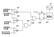
- FIG. 6 is a diagram showing an example of a schematic circuit configuration of the power supply abnormality detection unit 29.
- the instantaneous values of the current consumption detected by the instantaneous value detection unit 281 are both input to one input terminal of the first comparator 291 and the second comparator 292.
- the instantaneous value of the current consumption corresponding to an output power of 300 W is input as a reference value to the other input terminal of the first comparator 291.
- the instantaneous value of the current consumption corresponding to an output power of 50 W is input as a reference value to the other input terminal of the second comparator 292.
- the average value of the current consumption calculated by the average value calculation unit 282 is input to one input terminal of the third comparator 293, and the average value of the current consumption corresponding to a duty ratio of the PWM control signal of 16.6% is input as a reference value to the other input terminal.
- the output of the second comparator 292 and the output of the third comparator 293 are input to an AND operation gate 294, and the output of the AND operation gate 294 and the output of the first comparator 291 are input to an OR operation gate 295.
- the output of the OR gate 295 is input as a clock to a latch circuit 296 which receives as its data a predetermined voltage value (3.3 V in this example) corresponding to the "H" logic.
- the output of the latch circuit 296 is input to a relay driver 297 which turns on/off the relay 27.
- the reason why the average value of the current consumption corresponding to the duty ratio of the PWM control signal being 16.6% is used as the reference value input to the third comparator 293 is that since the duty ratio in intermittent mode is 10%, by setting it at 16.6%, it is possible to distinguish between intermittent mode and continuous mode even when fluctuations in the duty ratio are taken into account. That is, the third comparator 293 outputs "L” if the current consumption is in a state corresponding to normal intermittent mode, and outputs "H” if it is in any other state (duty ratio is 16.6% or more).
- the first comparator 291 outputs "H” if the instantaneous value of the current consumption is equal to or greater than the output power of 300 W, and the second comparator 292 outputs "H” if the instantaneous value of the current consumption is equal to or greater than the output power of 50 W.
- the AND gate 294 outputs "H” if the duty ratio is 16.6% or more and the instantaneous value of the current consumption is equal to or greater than the output power of 50 W.
- the OR gate 295 outputs "H” when the instantaneous value of the current consumption is equal to or greater than the output power of 300 W, or when the duty ratio is 16.6% or more and the instantaneous value of the current consumption is equal to or greater than the output power of 50 W.
- the latch circuit 296 is initially reset, for example, at the start of the plasma generation operation, and outputs "H” when the output of the OR gate 295 becomes “H” under the above-mentioned conditions (output Q becomes "H” and output Q bar becomes “L”).
- the relay drive unit 297 cuts off the relay 27, thereby cutting off the power supply to the microwave power source 25.
- the power supply abnormality detection unit 29 Since the power supply abnormality detection unit 29 operates as described above, as shown in FIG. 5, if the instantaneous value of the current consumption is equal to or exceeds an output power of 300 W, the power supply to the microwave power supply 25 is cut off regardless of the duty ratio. When the instantaneous value of the current consumption is equal to or exceeds an output power of 300 W, there is a high possibility that there is an abnormality in the microwave power supply 25. Therefore, by cutting off the power supply to the microwave power supply 25, it is possible to prevent excessive current from being supplied to the helical antenna 211, and to avoid secondary failures or fatal damage.
- the instantaneous value of the current consumption corresponds to an output power range of 50W or more and less than 300W
- the duty ratio is 16.6% or more
- the average output power from the microwave power supply 25 may exceed 50W. Therefore, by cutting off the power supply to the microwave power supply 25, it is possible to prevent excessive current from being supplied to the helical antenna 211.
- the instantaneous value of the current consumption corresponds to an output power range of 50W or more and less than 300W
- the duty ratio is less than 16.6%
- the average output power from the microwave power supply 25 will be within 50W. Therefore, the power supply to the microwave power supply 25 continues.
- the instantaneous value of the current consumption is less than the output power of 50W
- the power supply to the microwave power supply 25 continues regardless of the duty ratio.
- the mass spectrometer of this embodiment prevents excessive microwave power from being supplied to the plasma generation unit 21 due to an abnormality or malfunction of the microwave power supply 25 included in the radical generation unit 2 or the control unit 3 that controls the microwave power supply 25, and can prevent serious problems such as damage to the parts and members included in the plasma generation unit 21 and even to the parts and members around them.
- the power supply abnormality detection unit 29 can have a configuration other than that shown in FIG. 6 in order to realize the circuit protection function described above. It is also clear that the values of the output power and duty ratio for determining that an abnormality has occurred can be appropriately determined depending on the configuration, structure, control method, etc. of the device.
- the ion analyzer according to the present invention is applied to a Q-TOF mass analyzer, but it is clear that the present invention is not limited to Q-TOF types.
- the present invention can also be applied to triple quadrupole mass analyzers, ion trap mass analyzers, ion trap time-of-flight mass analyzers, and the like.
- the present invention can also be applied to devices in general that dissociate ions using radical species generated in plasma and analyze the product ions generated by the dissociation.
- the present invention can also be applied to ion mobility analyzers that separate and detect ions according to ion mobility, and ion mobility-mass analyzers that separate ions using both ion mobility and m/z.
- the configuration of the mass spectrometer described above, particularly the configuration of the radical generation unit 2 that generates radical species, is merely one example, and it goes without saying that any configuration that can generate radical species using plasma can be modified as appropriate.
- the radical species referred to here include hydroxyl radicals, oxygen radicals, nitrogen radicals, hydrogen radicals, and the like that are generally used in radical attachment and dissociation, as well as various molecules and atoms that are in an excited state or in a metastable state when energy is applied.
- One aspect of the ion analyzer according to the present invention is an ion analyzer that introduces radical species generated in plasma into a reaction chamber, and brings the radical species into contact with ions derived from a sample in the reaction chamber to dissociate the ions, a generation chamber into which a source gas is introduced; a power supply unit that supplies high frequency power for generating plasma inside the generation chamber; A control unit that controls the power supply unit to adjust the high frequency power supplied to the generation chamber, and switches between an intermittent mode in which the high frequency power is intermittently supplied and a continuous mode in which the high frequency power having a lower output power than that of the high frequency power supplied in the intermittent mode is continuously supplied; a current detection unit that detects a current consumption of the power supply unit; an abnormality response unit that cuts off power to be supplied to the power supply unit based on the detected value of the current consumption; Equipped with.
- the abnormality response unit cuts off the power supply by turning off a relay installed on the line that supplies power to the power supply unit.
- the power supplied from the high-frequency power supply unit to the generation chamber can be cut off. This makes it possible to avoid abnormal heating of the components of the generation unit due to excessive power supply and prevent secondary failures from occurring.
- the current detection unit includes an instantaneous value detection unit that detects the instantaneous value of the current consumption, and the abnormality response unit can determine whether or not to cut off power based on the detected instantaneous value.
- an abnormality in the power for generating plasma supplied to the generation chamber is detected by the instantaneous value of the current consumption, and if an abnormality is suspected, the power that operates the power supply unit is cut off.
- the power supplied to the generation chamber can be quickly stopped, and abnormal heating of, for example, a helical antenna for generating plasma can be more reliably prevented.
- the current detection unit further includes a corresponding value calculation unit that determines, based on the current consumption, a value corresponding to a duty ratio, which is the ratio of the period during which the power supplied from the power supply unit to the generation chamber is on/off, and the abnormality response unit can change the reference value for determining the instantaneous value according to the value corresponding to the duty ratio.
- high frequency power may be supplied to the generation chamber intermittently (intermittent mode) or continuously (continuous mode). Even if the instantaneous value of current consumption is the same, when high frequency power is supplied to the generation chamber continuously, the average power per unit time is greater than when it is supplied to the generation chamber intermittently, and there is a high possibility that the helical antenna, etc., will be abnormally heated.
- the corresponding value calculation unit can digitize the presence or absence of current consumption and smooth the digitized signal to determine the value corresponding to the duty ratio.
- the ion analyzer described in paragraph 4 can accurately determine the value corresponding to the duty ratio using a simple and inexpensive circuit.
- Vacuum chamber 1000 Opening 10: Ionization chamber 101: ESI probe 102: Desolvation tube 11: First intermediate vacuum chamber 111: Ion guide 112: Skimmer 12: Second intermediate vacuum chamber 121: Ion guide 13: First analysis chamber 131: Quadrupole mass filter 132: Collision cell 1320: Opening 1321: Tube connection member 133: Multipole ion guide 134: Ion transport electrode 14: Second analysis chamber 141: Ion transport electrode 142: Orthogonal acceleration section 143: Acceleration electrode 144: Flight tube 145: Reflectron electrode 146: Ion detector 2: Radical generation section 20: Valve 21: Plasma generation section 210: Quartz tube 211: Helical antenna 212: Outer conductor section 213, 215: Permanent magnet 214: Casing 216: Microwave supply connector 217: Ultraviolet light source 218: Photodetector 220: Resonator adjustment mechanism 221: Magnet holder 222: Holding member 25: Microwave power source 26: Raw material gas
Landscapes
- Physics & Mathematics (AREA)
- Chemical & Material Sciences (AREA)
- Analytical Chemistry (AREA)
- Engineering & Computer Science (AREA)
- Plasma & Fusion (AREA)
- Electromagnetism (AREA)
- Spectroscopy & Molecular Physics (AREA)
- Other Investigation Or Analysis Of Materials By Electrical Means (AREA)
Abstract
本発明に係るイオン分析装置の一態様は、プラズマ中で生成したラジカル種を反応室(132)に導入し、該反応室において試料由来のイオンにラジカル種を接触させて該イオンを解離させるイオン分析装置であって、原料ガスがその内部に導入される生成室(210)と、生成室の内部にプラズマを生じさせるための高周波電力を供給する電力供給部(25)と、生成室に供給する高周波電力を調整するべく前記電力供給部を制御する制御部であって、高周波電力を間欠的に供給する間欠モードと、該間欠モードにおける高周波電力供給時に比べて出力電力が低い高周波電力を連続的に供給する連続モードと、を切り替える制御部(3)と、電力供給部の消費電流を検出する電流検出部(28)と、検出された消費電流の値に基いて電力供給部へ与える電力を遮断する異常対応部(29、27)と、を備える。
Description
本発明は、試料に含まれる目的成分由来のイオンを分析するイオン分析装置に関する。
試料に含まれる高分子化合物等の試料成分を同定したりその構造を解析したりするために、試料成分由来のイオンから特定のm/z(質量電荷比)を有するイオンを選別し、そのイオンを解離させて生成した種々のプロダクトイオンをm/zに応じて分離して検出する質量分析法が広く利用されている。イオンの解離手法としては様々な方法が知られているが、その一つとして、ヒドロキシル(OH)ラジカル、酸素ラジカル、窒素ラジカルなどの各種のラジカルをイオンに付着させることによって、炭素原子の不飽和結合や特定の官能基の位置でイオンを解離させるラジカル誘起(付着)解離法が知られている(特許文献1、2等参照)。
特許文献3には、ラジカル誘起解離法において使用するラジカルを生成するためのラジカル生成装置の一例が開示されている。このラジカル生成装置は、石英管とその外周に帯状の導電体を巻回した構成であるヘリカルアンテナを有しており、石英管の内部に水蒸気等の原料ガスを導入し、ヘリカルアンテナに高周波電力を供給することによって該石英管の内部にプラズマを発生させ、そのプラズマ中でラジカルを生成させる。また、強い磁場を発生する磁石を石英管の外側に配置し、この磁場を利用した電子サイクロトロン共鳴によって、石英管内のプラズマの密度を高めるとともにプラズマの生成を安定化させる。このラジカル生成装置は、プラズマの生成及び維持に、局所的な誘導型放電と電子サイクロトロン共鳴とを利用しているため、ECR-LICP(Electron Cyclotron Resonance - Localized Inductively Coupled Plasma)型と呼ばれることもある。
上記ラジカル生成装置では、プラズマを生成するために高周波電力を供給する必要があるが、大電力の高周波電力を供給し続けるとヘリカルアンテナが高温になり、石英管等の部材が熱膨張によって破損する等の問題が生じる懸念がある。これを回避するために、特許文献4に記載の装置では、パルス幅変調(PWM)制御によって高周波電力を間欠的に供給することで、プラズマの生成に必要な電力を供給しつつヘリカルアンテナ等の過度な温度上昇を抑えるようにしている。
上述したようなPWM制御により供給電力を調整する構成のラジカル生成装置を用いた質量分析装置では、PWM制御回路や高周波電源部などに故障が生じると、過大な高周波電力がヘリカルアンテナに供給されてしまう可能性がある。そうなると、石英管やその周囲の部材が異常に加熱され、熱衝撃や部材による膨張率の差異などによって破損する等の、2次的で深刻な故障を引き起こす懸念がある。
一般的な装置では、故障等により電子回路に過電流が流れるのを防止するために、ヒューズを挿入したり温度センサーとリレーとの組合せを用いたりする。しかしながら、ラジカル生成装置では、動作時に当該装置やその周囲に強い磁場が発生するため、電磁誘導作用によってヒューズや温度センサーなどの回路素子に不所望の電流が流れ、当該素子が適切に動作しない場合がある。そのため、上記ラジカル生成装置では、こうした一般の装置における過電流対策は有効に機能しない。
本発明はこうした課題を解決するために成されたものであり、その主たる目的は、プラズマ生成用の高周波電源部や制御系回路などに故障が生じた場合であっても、プラズマ生成部に過大な高周波電力が供給されることを有効に防止することで、2次的な故障の発生を回避することができるイオン分析装置を提供することである。
本発明に係るイオン分析装置の一態様は、プラズマ中で生成したラジカル種を反応室に導入し、該反応室において試料由来のイオンにラジカル種を接触させて該イオンを解離させるイオン分析装置であって、
原料ガスがその内部に導入される生成室と、
前記生成室の内部にプラズマを生じさせるための高周波電力を供給する電力供給部と、
前記生成室に供給する高周波電力を調整するべく前記電力供給部を制御する制御部であって、高周波電力を間欠的に供給する間欠モードと、該間欠モードにおける高周波電力供給時に比べて出力電力が低い高周波電力を連続的に供給する連続モードと、を切り替える制御部と、
前記電力供給部の消費電流を検出する電流検出部と、
検出された前記消費電流の値に基いて前記電力供給部へ与える電力を遮断する異常対応部と、
を備える。
原料ガスがその内部に導入される生成室と、
前記生成室の内部にプラズマを生じさせるための高周波電力を供給する電力供給部と、
前記生成室に供給する高周波電力を調整するべく前記電力供給部を制御する制御部であって、高周波電力を間欠的に供給する間欠モードと、該間欠モードにおける高周波電力供給時に比べて出力電力が低い高周波電力を連続的に供給する連続モードと、を切り替える制御部と、
前記電力供給部の消費電流を検出する電流検出部と、
検出された前記消費電流の値に基いて前記電力供給部へ与える電力を遮断する異常対応部と、
を備える。
本発明に係る上記態様のイオン分析装置によれば、プラズマに電力を供給する高周波電源部や該電源部の動作を制御する制御系回路の故障などによって、高周波電源部における消費電流が異常に増加した場合に、高周波電源部から生成室に供給される電力を遮断することができる。これにより、過大な電力供給による生成部の部材の異常な加熱を回避し、2次的な故障の発生を防止することができる。
本発明に係るイオン分析装置の一実施形態について、添付図面を参照して説明する。以下、イオン分析装置の一実施形態として質量分析装置について説明するが、イオン移動度分析装置やイオン移動度-質量分析装置でもよいことは後述の説明から明らかである。
図1は、本実施形態の質量分析装置の概略構成図である。この質量分析装置は、大気圧イオン源を備えた四重極-飛行時間型(Q-TOF型)質量分析装置である。
図1に示すように、この質量分析装置は、イオン化室10と真空チャンバー1とを有する。イオン化室10内は略大気圧雰囲気である。真空チャンバー1の内部は複数(本実施形態では4室)に区画されており、イオン化室10に近い側から順に、第1中間真空室11、第2中間真空室12、第1分析室13、及び第2分析室14となっている。これらの各室はそれぞれ、図示しない真空ポンプ(ロータリーポンプ及び/又はターボ分子ポンプ)により真空排気されており、イオン化室10から第2分析室14に向かうに従って順に真空度が高まる、多段差動排気系の構成を呈する。
イオン化室10には、液体試料に電荷を付与して噴霧するエレクトロスプレーイオン化(ESI)プローブ101が設置されている。イオン化室10と第1中間真空室11とは、細径の脱溶媒管102を通して連通している。第1中間真空室11と第2中間真空室12とは、頂部に小孔を有するスキマー112で隔てられている。第1中間真空室11及び第2中間真空室12にはそれぞれ、イオンガイド111、121が配置されている。第1分析室13には、イオン光軸Cに沿って、イオンをm/zに応じて分離する四重極マスフィルター131、多重極イオンガイド133を内部に備えたコリジョンセル132、及びイオンを輸送するためのイオン輸送電極134、が配置されている。四重極マスフィルター131及び多重極イオンガイド133はそれぞれ複数のロッド電極で構成され、イオン輸送電極134は複数のリング状電極で構成されている。
コリジョンセル132の壁面には開口1320が形成され、一端がこの開口1320を囲うように、筒状の管接続部材1321が設けられている。この管接続部材1321の内側にはラジカル生成部2から延伸する石英管210が挿通され、該石英管210の末端は開口1320を通してコリジョンセル132内に突出している。コリジョンセル132では、後述するように、ラジカル生成部2から供給されるラジカル種によってイオンを解離させる。なお、ここでは図示していないが、コリジョンセル132には、ラジカル生成部2以外に、コリジョンセル132内で衝突誘起解離(CID)を生じさせるためのガスが供給されるようにすることができる。
第2分析室14には、第1分析室13から入射したイオンを輸送するためのイオン輸送電極141、イオン光軸Cを挟んで対向配置された一組の電極を含む直交加速部142、加速電極143、飛行空間を内部に形成するフライトチューブ144、飛行空間においてイオンの折り返し軌道を形成するリフレクトロン電極145、及びイオンを検出するイオン検出器146、を備える。イオン検出器146は例えばマルチチャンネルプレート型検出器である。イオン検出器146による検出信号はデータ処理部4に入力される。制御部3は、ラジカル生成部2、データ処理部4のほか、各部に電圧等を印加する電源等を制御する。
制御部3の制御の下で行われる、上記構成の質量分析装置における典型的な分析動作は次の通りである。
ESIプローブ101は、例えば液体クロマトグラフのカラム出口から供給される液体試料に電荷を付与しながら該液体試料をイオン化室10内に噴霧し、液体試料中の化合物をイオン化する。生成されたイオンは脱溶媒管102を通って第1中間真空室11へ送られる。第1中間真空室11に入射したイオンは、イオンガイド111、スキマー112の小孔、イオンガイド121を経て、第1分析室13まで送られ、四重極マスフィルター131に導入される。
ESIプローブ101は、例えば液体クロマトグラフのカラム出口から供給される液体試料に電荷を付与しながら該液体試料をイオン化室10内に噴霧し、液体試料中の化合物をイオン化する。生成されたイオンは脱溶媒管102を通って第1中間真空室11へ送られる。第1中間真空室11に入射したイオンは、イオンガイド111、スキマー112の小孔、イオンガイド121を経て、第1分析室13まで送られ、四重極マスフィルター131に導入される。
導入された各種イオンの中で特定のm/z値を有するイオンのみが選択的に四重極マスフィルター131を通過し、コリジョンセル132に導入される。コリジョンセル132内にはラジカル生成部2から石英管210を通してラジカル種が導入され、コリジョンセル132に導入されたイオンはこのラジカル種と反応して解離する。解離により生成された各種のプロダクトイオンは、コリジョンセル132から出てイオン輸送電極134、141を経て直交加速部142に導入される。
イオン光軸Cに沿って直交加速部142に導入されたイオンは、所定のタイミングでイオン光軸Cに略直交する方向に射出される。射出されたイオンは加速電極143で加速され、フライトチューブ144内の飛行空間に導入される。イオンは、リフレクトロン電極145により形成される電場により折り返し飛行し、最終的にイオン検出器146に到達する。イオン検出器146は、入射したイオンの量に応じた検出信号をデータ処理部4へと出力する。イオンが直交加速部142を出発した時点からイオン検出器146に到達する時点までの時間、つまりイオンの飛行時間は、そのイオンのm/z値に依存する。そこで、データ処理部4は、検出信号に基いて飛行時間とイオン強度との関係を示す飛行時間スペクトルを作成し、飛行時間をm/z値に換算することでマススペクトルを作成する。
次いで、ラジカル生成部2の詳細な構成とその動作を説明する。
図1に示すように、ラジカル生成部2はプラズマ生成部21を含む。プラズマ生成部21は、原料ガス供給源26から供給される、水蒸気等の原料ガスを基にプラズマを生成し、該プラズマ中で発生したラジカルをコリジョンセル132に供給する。マイクロ波電源25は、プラズマを生成するための高周波(マイクロ波)電力をプラズマ生成部21に供給する。原料ガス供給源26からプラズマ生成部21へ供給される原料ガスの量は、原料ガス供給源26と石英管210とを結ぶ流路に設けられたバルブ20によって調整される。
図1に示すように、ラジカル生成部2はプラズマ生成部21を含む。プラズマ生成部21は、原料ガス供給源26から供給される、水蒸気等の原料ガスを基にプラズマを生成し、該プラズマ中で発生したラジカルをコリジョンセル132に供給する。マイクロ波電源25は、プラズマを生成するための高周波(マイクロ波)電力をプラズマ生成部21に供給する。原料ガス供給源26からプラズマ生成部21へ供給される原料ガスの量は、原料ガス供給源26と石英管210とを結ぶ流路に設けられたバルブ20によって調整される。
図2は、ラジカル生成部2におけるプラズマ生成部21を中心とする要部の縦断面図である。
プラズマ生成部21は、長い石英管210と、石英管210の一部の外周に螺旋状に巻回された帯状の導電体であるヘリカルアンテナ211と、石英管210と同軸で、その内径が石英管210の外径よりも一回り大きい円筒開口を有する導電体からなる外側導体部212と、外側導体部212に埋設された永久磁石213と、外側導体部212を保持するケーシング214と、ケーシング214の底部に配置された永久磁石215と、を有する。ケーシング214には、マイクロ波供給コネクター216、紫外光光源217、及び光検出器218、が設けられている。紫外光光源217から深紫外光を石英管210に照射すると、石英管210の壁面から電子が放出され、この電子によってプラズマの着火が誘発される。
プラズマ生成部21は、長い石英管210と、石英管210の一部の外周に螺旋状に巻回された帯状の導電体であるヘリカルアンテナ211と、石英管210と同軸で、その内径が石英管210の外径よりも一回り大きい円筒開口を有する導電体からなる外側導体部212と、外側導体部212に埋設された永久磁石213と、外側導体部212を保持するケーシング214と、ケーシング214の底部に配置された永久磁石215と、を有する。ケーシング214には、マイクロ波供給コネクター216、紫外光光源217、及び光検出器218、が設けられている。紫外光光源217から深紫外光を石英管210に照射すると、石英管210の壁面から電子が放出され、この電子によってプラズマの着火が誘発される。
石英管210は、原料ガス供給源26から原料ガスが導入される原料導入管であるとともに、その内部が生成室及びラジカル流路となる。マイクロ波供給コネクター216は同軸コネクターであり、同軸ケーブルを介してマイクロ波電源25に接続される。マイクロ波供給コネクター216の導電線は、ヘリカルアンテナ211の一端(図2では下端)に接続されている。また、図示しないものの、外側導体部212は接地されている。ヘリカルアンテナ211の一部と外側導体部212とは共振器調整機構220を介して電気的に接続されており、その接続位置においてヘリカルアンテナ211は接地されている。ヘリカルアンテナ211、外側導体部212、共振器調整機構220などによって、電子サイクロトロン共鳴の共振器が構成されている。共振器調整機構220は共振器の調整に用いられ、例えば特許文献3に記載のものである。
このプラズマ生成部21は、プラズマの生成及び維持に、局所的な誘導結合型放電と電子サイクロトロン共鳴とを利用する、ECR-LICP型と呼ばれる構成である。
ケーシング214の底面には、略円盤状の磁石ホルダー221が取り付けられている。ケーシング214と磁石ホルダー221は、石英管210を保持する保持部材222として機能する。磁石ホルダー221の中央部には石英管210を挿通する開口が形成されている。図2に示すように、プラズマ生成部21は真空チャンバー1に形成された開口を覆うように真空チャンバー1の外面に装着され、保持部材222により保持された石英管210は、コリジョンセル132と真空チャンバー1との間を繋ぐ管接続部材1321の内側に挿通されてコリジョンセル132内にまで至る。石英管210の内部とコリジョンセル132の内部とは連通しているため、石英管210に原料ガスが供給されない状態では石英管210の内部も真空状態になる。
次に、本実施形態の質量分析装置において、ラジカル生成部2を動作させることでラジカル種をコリジョンセル132に供給し、分析を実行する際の制御動作を説明する。図3は、このときの制御フローチャートである。図4は、プラズマ生成のための制御信号波形の概念及びマイクロ波波形の一例を示す図である。図4の(A)は、横軸が時間経過、縦軸が供給されるマイクロ波電力の大きさを示す疑似的な波形図であり、(B)はヘリカルアンテナ211に印加される電圧の時間変化を示す図である。
上述したように、ラジカル生成時には制御部3はバルブ20を開放し、所定流量の原料ガスを石英管210に流す。ここでは原料ガスは水蒸気であるとする。制御部3はプラズマが点灯していない状況で、プラズマを点灯させるために、図4(A)に示すような所定のデューティー比(1周期に占めるオン期間の割合)であるパルス幅変調(PWM)制御信号をマイクロ波電源25に入力する。これに応じてマイクロ波電源25は、図4(B)に示すように、PWM制御信号がオンである期間(図4(A)では波高値がPa又はPbである期間)には所定周波数で所定出力のマイクロ波を出力し、PWM制御信号がオフである期間(図4(A)では波高値が0である期間)にはマイクロ波の出力を停止する。プラズマの点灯を促すための紫外光光源217による深紫外光の放出は、PWM制御信号がオン/オフのいずれであるかに拘わらず連続的に行われる。
即ち、制御部3に含まれるPWM制御回路及びマイクロ波電源25は、PWM駆動によってプラズマ点灯を試みる(ステップS1)。一例として、PWM制御信号の周波数は100Hzであり、デューティー比は通常10~20%の範囲であって、ここでは10%とする。また、同様に一例として、マイクロ波の周波数は2.5GHzであり、マイクロ波の出力電力は250Wである。この出力電力はプラズマが点灯するのに十分な電力である。但し、これら値は単に一例であり、適宜に変更可能である。
PWM制御信号がオンである期間つまりマイクロ波電力が石英管210内である生成室に供給されている期間には、通常、原料ガスである水蒸気が電離されてプラズマが点灯する。一方、PWM制御信号がオフである期間つまりマイクロ波電力の供給が停止されている期間には、プラズマは消灯する。従って、PWM制御信号がオン/オフに切り替えられるのに伴って、プラズマは点灯、消灯を繰り返す。但し、実際には、PWM制御信号がオフからオンに変化してマイクロ波電力が供給されても、プラズマが点灯しない場合もあり得る。
生成室内に配置されている光検出器218は、プラズマから発せられる光の波長を含む波長帯域の光を検出する。光検出器218は、紫外光光源217から発せられる光を検出しないように、該光の波長に対して感度を持たないことが好ましい。従って、ここでは、光検出器218として可視光領域に感度を有する(紫外光領域に対する感度がない又は感度が低い)フォトダイオードを用いる。これにより、紫外光光源217から発せられる光の影響を受けることなく、プラズマの発光を良好に検出することができる。
制御部3は、プラズマ点灯開始時点(PWM制御信号のオン/オフの切替えを開始した時点)から所定の時間(例えば1秒~10秒)だけ経過した時点において、光検出器218からの出力信号をモニターし、その信号値に基いてプラズマが点灯しているか否かを判断する。
なお、PWM制御信号のオン/オフの切替えに伴ってプラズマが点灯/消灯すると、それに応じて光検出器218による検出信号も変化するが、ここでは、PWM制御信号の周期(例えば100Hz)に同期した光強度の変化を検出する必要はない。何故なら、上述したように、PWM制御信号がオン期間であるときであってもプラズマが必ず点灯するとは限らず、その確率は低いもののプラズマが消灯したままの状態になる場合があり得るからである。そこで、例えば光検出器218による検出信号を適宜の時定数の平滑化回路や積分回路に入力して、検出信号を所定時間に亘り平滑化した又は積分した信号を取得し、その信号を所定の閾値と比較することで、全体としてプラズマが点灯状態となっているか否かを判断することができる。勿論、こうした処理をデジタル的に行うこともできるし、それ以外の回路を用いて、PWM制御期間(図4において「PWM」で示した期間)に全体としてプラズマが点灯状態となっているか否かを判断することもできる。
制御部3はステップS2においてプラズマが点灯状態であると判断されるまで待ち、点灯状態になったならば、ステップS3へと移行する。プラズマが点灯状態とならずに所定の上限時間(例えば10秒以上の適宜の時間)が経過した場合には、例えばマイクロ波電力の供給経路に異常がある、原料ガスが適切に供給されていない等の、何らかの異常である可能性が高いため、例えば異常を報知する等の対応を採ることができる。
ステップS3において、制御部3は、PWM制御信号がオン期間であるタイミングからマイクロ波電力を連続的に供給するように、マイクロ波電源25を制御する。即ち、間欠的にマイクロ波電力を供給する間欠モードから連続的にマイクロ波電力を供給する連続モードへ制御モードを切り替える。但し、図4(B)に示すように、連続モードでは、瞬時的な出力電力を間欠モードでの瞬時的な出力電力に比べて低下させる。これは、間欠モードのときのような瞬時的に大きな出力電力を連続的に供給し続けると、ヘリカルアンテナ211の発熱が大きくなり過ぎ、ヘリカルアンテナ211に接している石英管210等の部品が高温になって熱膨張によって破損する等のおそれがあるからである。
一般に、プラズマは完全に消灯している状態から点灯し始める際には大きな電力を要するが、一旦プラズマが点灯すると、供給する電力を下げても点灯状態が維持される。従って、PWM制御信号のオン期間であってプラズマが点灯している状態で連続モードに移行した場合、一般的には、その直前の点灯状態が継続される。しかしながら、上述したように、間欠モードにおいてPWM制御信号のオン期間であっても必ずしもプラズマが点灯状態であるとは限らず、PWM制御信号のオン期間であってプラズマが点灯していない状態のときに連続モードに移行する制御が行われることもある。その場合には、間欠モードから連続モードに移行したあともプラズマは消灯状態である。また、PWM制御信号がオンしている期間でプラズマが点灯状態であるときに連続モードに移行する制御が行われた場合であっても、連続モードへの移行時にプラズマが消灯してしまうこともあり得る。
そこで、制御部3は間欠モードから連続モードへ移行したあと、光検出器218からの出力信号をモニターし、その信号値に基いてプラズマが点灯しているか否かを確認する(ステップS4)。そして、プラズマが点灯していると判断できた場合(ステップS5でYES)にはステップS5からS6へと進み、ラジカル付着解離を利用したMS/MS分析を開始する。一方、連続モードへの移行後にプラズマが点灯していないと判断できる場合(ステップS5でNO)には、ステップS5からS1へと戻り、制御部3はプラズマの点灯開始制御を再試行する。
連続モードでは、間欠モードに比べて瞬時的な出力電力は低いものの、プラズマの点灯/消灯が繰り返されないため、プラズマの状態が安定し易い。従って、本実施形態の質量分析装置では、生成室内に安定的にプラズマが形成され、該プラズマ中で生成されたラジカルが安定してコリジョンセル132内に供給される状態でMS/MS分析を実行することができる。それにより、ラジカル付着解離によって生成されたプロダクトイオンを安定的に且つ良好に検出することができる。
上述したように、ヘリカルアンテナ211にマイクロ波電力が供給されるとヘリカルアンテナ211が発熱し、石英管210等の部材の温度が上昇する。ラジカル生成部2の熱は石英管210等を通して質量分離部へも伝わり、質量分析性能に影響を与える場合がある。例えば、熱によってフライトチューブ144が膨張したり、リフレクトロン電極145の電極間隔が変化したりすると、同じm/z値を有するイオンの飛行時間が変化し質量誤差が大きくなる等の悪影響が考えられる。間欠モード、連続モードのいずれでも熱の発生を完全に抑えることはできないが、質量分析性能への影響を抑えるには、間欠モードと連続モードとで発熱量を概ね揃えることが望ましい。そこで、間欠モードと連続モードとで単位時間当たりに供給する電力、つまりは平均電力を概ね揃えるとよい。
具体的には、間欠モードにおける瞬時的な出力電力をPa、間欠モードにおけるPWM制御信号のデューティー比をD(但し、常時オンではD=1、常時オフではD=0とする)、連続モードにおける瞬時的な出力電力をPbとした場合、
Pa×D≒Pb …(1)
となるようにすればよい。
これにより、間欠モードから連続モードに移行した際のラジカル生成部2での発熱量の変化を抑え、連続モード移行後にすぐにMS/MS分析を開始しても質量分析性能の低下を軽減することができる。
Pa×D≒Pb …(1)
となるようにすればよい。
これにより、間欠モードから連続モードに移行した際のラジカル生成部2での発熱量の変化を抑え、連続モード移行後にすぐにMS/MS分析を開始しても質量分析性能の低下を軽減することができる。
制御部3が上述したように適切なPWM制御信号をマイクロ波電源25に供給し、マイクロ波電源25がこの制御信号に応じてマイクロ波出力のオン/オフ動作やその出力電力の調整を適切に行っている状態では、ラジカル生成部2の動作は良好である。ところが、制御部3に含まれるPWM制御回路やマイクロ波電源25などに故障が発生した場合、過剰な出力電力がヘリカルアンテナ211に供給され、ヘリカルアンテナ211が異常に加熱される可能性がある。これは、例えば、PWM制御回路に故障が生じ、瞬時的な出力電力をPaとしてPWM制御信号が連続的にオンとなるような場合である。そこで、本実施形態の質量分析装置では、PWM制御回路やマイクロ波電源25などに動作異常や故障が生じた場合であっても、プラズマ生成部21に過剰な電力が供給されないように、具体的にはヘリカルアンテナ211に過剰な大きさの電流が供給されないようにする、一種の回路保護機能を有する。
図1に示すように、上記回路保護機能として、ラジカル生成部2は、電流検出部28と電力供給異常検知部29とを含む。電流検出部28は、マイクロ波電源25の消費電流を検出するものであって、瞬時値検出部281と平均値算出部282とを含む。瞬時値検出部281は、マイクロ波電源25において時々刻々と変化する消費電流の瞬時値を検出する。一方、平均値算出部282は、単位時間当たりの消費電流の平均値をリアルタイムで算出する。具体的には例えば平均値算出部282は、まず消費電流の有無を「H」、「L」の2値信号でリアルタイムで出力し、「H」レベルを+5V、「L」レベルを0Vの電圧値として、その電圧値の変動を単位時間内で平滑化することによって、消費電流の平均値に対応した値を求めるものとすることができる。勿論、平均値算出部282の構成はこれに限らない。
電力供給異常検知部29は電流検出部28からの信号に基いて、マイクロ波電源25からプラズマ生成部21へ供給されるマイクロ波電力が異常であるか否かを判断するものである。電力供給異常検知部29は、異常であると判断した場合には、マイクロ波電源25を動作させるための電力を供給する電源線に挿入されたリレー27を切断し、マイクロ波電源25への電力供給を遮断する。
図5は消費電流の瞬時値と供給電力の遮断/非遮断との関係を示す図、図6は電力供給異常検知部29の概略回路構成の一例を示す図である。
図6おいて、第1コンパレーター291及び第2コンパレーター292の一方の入力端には、瞬時値検出部281で検出された消費電流の瞬時値がともに入力される。第1コンパレーター291の他方の入力端には、出力電力300Wに相当する消費電流の瞬時値が基準値として入力される。第2コンパレーター292の他方の入力端には、出力電力50Wに相当する消費電流の瞬時値が基準値として入力される。第3コンパレーター293ーの一方の入力端には、平均値算出部282で算出された消費電流の平均値が入力され、他方の入力端にはPWM制御信号のデューティー比が16.6%である場合に相当する消費電流の平均値が基準値として入力される。第2コンパレーター292の出力と第3コンパレーター293の出力はアンド演算ゲート294に入力され、アンド演算ゲート294の出力と第1コンパレーター291の出力はオア演算ゲート295に入力される。オア演算ゲート295の出力は、「H」論理に対応する所定の電圧値(本例では3.3V)をデータ入力とするラッチ回路296にクロックとして入力される。ラッチ回路296の出力は、リレー27を導通/遮断するリレー駆動部297に入力される。
図6おいて、第1コンパレーター291及び第2コンパレーター292の一方の入力端には、瞬時値検出部281で検出された消費電流の瞬時値がともに入力される。第1コンパレーター291の他方の入力端には、出力電力300Wに相当する消費電流の瞬時値が基準値として入力される。第2コンパレーター292の他方の入力端には、出力電力50Wに相当する消費電流の瞬時値が基準値として入力される。第3コンパレーター293ーの一方の入力端には、平均値算出部282で算出された消費電流の平均値が入力され、他方の入力端にはPWM制御信号のデューティー比が16.6%である場合に相当する消費電流の平均値が基準値として入力される。第2コンパレーター292の出力と第3コンパレーター293の出力はアンド演算ゲート294に入力され、アンド演算ゲート294の出力と第1コンパレーター291の出力はオア演算ゲート295に入力される。オア演算ゲート295の出力は、「H」論理に対応する所定の電圧値(本例では3.3V)をデータ入力とするラッチ回路296にクロックとして入力される。ラッチ回路296の出力は、リレー27を導通/遮断するリレー駆動部297に入力される。
ここで、PWM制御信号のデューティー比が16.6%である場合に相当する消費電流の平均値を第3コンパレーター293の基準値入力としているのは、間欠モードでのデューティー比が10%であるため、デューティー比の変動を考慮しても、16.6%としておくことで間欠モードと連続モードとの識別が可能であるためである。即ち、第3コンパレーター293は、そのときの消費電流の流れ方が正常な間欠モードに相当する状態であれば「L」を、それ以外の状態(デューティー比が16.6%以上)であれば「H」を出力する。また、第1コンパレーター291は、そのときの消費電流の瞬時値が出力電力300Wに相当する場合以上であれば「H」を出力し、第2コンパレーター292は、そのときの消費電流の瞬時値が出力電力50Wに相当する場合以上であれば「H」を出力する。
アンド演算ゲート294は、デューティー比が16.6%以上であって且つ消費電流の瞬時値が出力電力50Wに相当する場合以上であれば「H」を出力する。オア演算ゲート295は、消費電流の瞬時値が出力電力300Wに相当する場合以上であるとき、又は、デューティー比が16.6%以上であって且つ消費電流の瞬時値が出力電力50Wに相当する場合以上であるときに「H」を出力する。ラッチ回路296は、例えばプラズマ生成動作開始時など初期的にリセットされ、オア演算ゲート295の出力が上述したような条件の下で「H」になると「H」を出力する(出力Qは「H」、出力Qバーは「L」になる)。ラッチ回路296の出力が「H」になると、リレー駆動部297はリレー27を切断することで、マイクロ波電源25への電力供給を遮断する。
電力供給異常検知部29は上述したように動作するため、図5に示すように、消費電流の瞬時値が出力電力300Wに相当する場合以上であると、デューティー比に拘わらず、マイクロ波電源25への電力供給は遮断される。消費電流の瞬時値が出力電力300Wに相当する場合以上であるときには、マイクロ波電源25の異常である可能性が高い。そこで、マイクロ波電源25への電力供給を遮断することで、ヘリカルアンテナ211に過剰な電流が供給されることを回避し、2次的な故障や致命的な破損を避けることができる。
また、消費電流の瞬時値が出力電力50W以上300W未満の範囲に相当する場合には、デューティー比が16.6%以上であると、マイクロ波電源25からの平均的な出力電力が50Wを超える可能性がある。そこで、マイクロ波電源25への電力供給を遮断することで、ヘリカルアンテナ211に過剰な電流が供給されることを回避する。一方、消費電流の瞬時値が出力電力50W以上300W未満の範囲に相当する場合であっても、デューティー比が16.6%未満であれば、マイクロ波電源25からの平均的な出力電力は50W以内に収まる。従って、マイクロ波電源25への電力供給は継続される。また、消費電流の瞬時値が出力電力50Wに相当する場合未満であれば、デューティー比に拘わらず、マイクロ波電源25への電力供給は継続される。
以上のようにして、本実施形態の質量分析装置では、ラジカル生成部2に含まれるマイクロ波電源25やマイクロ波電源25を制御する制御部3の異常や故障によりプラズマ生成部21に過大なマイクロ波電力が供給されることを防止し、該プラズマ生成部21に含まれる部品や部材、さらには、その周辺の部品や部材が破損する等の重大な障害の発生を未然に回避することができる。
勿論、上述したような回路保護機能を実現するために、電力供給異常検知部29を図6に示す構成以外の構成とすることができることは明らかである。また、異常であると判断するための出力電力やデューティー比の値は、装置の構成や構造、制御方法等に応じて適宜決めればよいことも明らかである。
上記実施形態は、本発明に係るイオン分析装置をQ-TOF型質量分析装置に適用した例であるが、Q-TOF型に限らないことは明らかである。具体的には、トリプル四重極型質量分析装置、イオントラップ型質量分析装置、イオントラップ飛行時間型質量分析装置などにも本発明を適用可能である。また、本発明は、プラズマ中で生成したラジカル種を用いてイオンを解離させ、その解離により生成されたプロダクトイオンを分析する装置全般に適用し得る。具体的には、例えば、イオンをイオン移動度に応じて分離して検出するイオン移動度分析装置や、イオンをイオン移動度とm/zの両方を用いて分離するイオン移動度-質量分析装置などにも本発明を適用し得る。
また、上記説明した質量分析装置の構成、特にラジカル種を生成するラジカル生成部2の構成は単に一例であり、プラズマによりラジカル種を生成可能な構成であれば適宜に変形可能であることは当然である。また、ここいうラジカル種は、一般的にラジカル付着解離に利用されるヒドロキシルラジカル、酸素ラジカル、窒素ラジカル、水素ラジカルなどのほか、エネルギーが与えられて励起された状態にある又は準安定な状態になる各種の分子、原子なども含む。
即ち、上記実施形態は本発明の単なる一例にすぎず、本発明の趣旨の範囲で適宜に変形、追加等を行っても本願特許請求の範囲に包含されることは明らかである。
[種々の態様]
上述した例示的な実施形態は、以下の態様の具体例であることが当業者により理解される。
上述した例示的な実施形態は、以下の態様の具体例であることが当業者により理解される。
(第1項)本発明に係るイオン分析装置の一態様は、プラズマ中で生成したラジカル種を反応室に導入し、該反応室において試料由来のイオンにラジカル種を接触させて該イオンを解離させるイオン分析装置であって、
原料ガスがその内部に導入される生成室と、
前記生成室の内部にプラズマを生じさせるための高周波電力を供給する電力供給部と、
前記生成室に供給する高周波電力を調整するべく前記電力供給部を制御する制御部であって、高周波電力を間欠的に供給する間欠モードと、該間欠モードにおける高周波電力供給時に比べて出力電力が低い高周波電力を連続的に供給する連続モードと、を切り替える制御部と、
前記電力供給部の消費電流を検出する電流検出部と、
検出された前記消費電流の値に基いて前記電力供給部へ与える電力を遮断する異常対応部と、
を備える。
原料ガスがその内部に導入される生成室と、
前記生成室の内部にプラズマを生じさせるための高周波電力を供給する電力供給部と、
前記生成室に供給する高周波電力を調整するべく前記電力供給部を制御する制御部であって、高周波電力を間欠的に供給する間欠モードと、該間欠モードにおける高周波電力供給時に比べて出力電力が低い高周波電力を連続的に供給する連続モードと、を切り替える制御部と、
前記電力供給部の消費電流を検出する電流検出部と、
検出された前記消費電流の値に基いて前記電力供給部へ与える電力を遮断する異常対応部と、
を備える。
電力供給部や制御部の故障等によって電力供給部から生成室に供給される電力が異常に増加すると、電力供給部における消費電流も異常に増加する。第1項に記載のイオン分析装置において、異常対応部は、例えば、電流検出部により消費電流が予め決めた閾値を超えたと判断すると、電力供給部へ電力を供給する線路上に設けたリレーをオフする等によって電力の供給を遮断する。このようにして、第1項に記載のイオン分析装置によれば、プラズマに電力を供給する高周波電源部(上記電力供給部)や該電源部の動作を制御する制御系回路(上記制御部)の故障などによって、高周波電源部における消費電流が異常に増加した場合に、高周波電源部から生成室に供給される電力を遮断することができる。これにより、過大な電力供給による生成部の部材の異常な加熱を回避し、2次的な故障の発生を防止することができる。
(第2項)第1項に記載のイオン分析装置において、前記電流検出部は消費電流の瞬時値を検出する瞬時値検出部を含み、前記異常対応部は検出された瞬時値に基いて電力の遮断の要否を判断するものとすることができる。
第2項に記載のイオン分析装置では、消費電流の瞬時値によって生成室へ供給されるプラズマ生成用の電力の異常を検知し、異常と推定される場合に電力供給部を動作させる電力を遮断する。これにより、第2項に記載のイオン分析装置によれば、電力供給部や制御部の故障などが生じた際に、生成室へ供給される電力を迅速に停止することができ、例えばプラズマを生成するためのヘリカルアンテナ等の異常加熱をより確実に防止することができる。
(第3項)第2項に記載のイオン分析装置において、前記電流検出部はさらに、前記電力供給部から前記生成室に供給される電力がオン/オフされる期間の割合であるデューティー比に対応する値を消費電流に基いて求める対応値算出部を含み、前記異常対応部は該デューティー比に対応する値に応じて、瞬時値を判定する基準の値を変更するものとすることができる。
第1項に記載のイオン分析装置では、高周波電力が間欠的に生成室に供給される場合(間欠モード)と連続的に生成室に供給される場合(連続モード)とがある。仮に消費電流の瞬時値が同じであっても、高周波電力が連続的に生成室に供給されている場合には間欠的に生成室に供給されている場合に比べて単位時間当たりの平均電力が大きくなり、ヘリカルアンテナ等が異常加熱を生じる可能性が高い。
これに対し、第3項に記載のイオン分析装置において、デューティー比に対応する値が適宜の値よりも大きい場合には、実質的に高周波電力が連続的に生成室に供給されているものとみることができる。そこで、デューティー比に対応する値が適宜の値よりも大きい場合には小さい場合に比べて、異常である(つまりは電力を遮断する必要がある)と判定する基準の値を低くし、より低い瞬時値で以て異常であると判断できるようにする。これにより、第3項に記載のイオン分析装置によれば、高周波電力が間欠的に生成室に供給される場合でも連続的に生成室に供給されている場合でも、ヘリカルアンテナ等が異常に加熱される可能性がある際に確実に高周波電力の供給を停止することができる。
(第4項)第3項に記載のイオン分析装置において、前記対応値算出部は、消費電流の有無を二値化し、その二値化後の信号を平滑化することで、前記デューティー比に対応する値を求めるものとすることができる。
第4項に記載のイオン分析装置では、簡単で安価な回路によって、デューティー比に対応する値を的確に求めることができる。
1…真空チャンバー
1000…開口
10…イオン化室
101…ESIプローブ
102…脱溶媒管
11…第1中間真空室
111…イオンガイド
112…スキマー
12…第2中間真空室
121…イオンガイド
13…第1分析室
131…四重極マスフィルター
132…コリジョンセル
1320…開口
1321…管接続部材
133…多重極イオンガイド
134…イオン輸送電極
14…第2分析室
141…イオン輸送電極
142…直交加速部
143…加速電極
144…フライトチューブ
145…リフレクトロン電極
146…イオン検出器
2…ラジカル生成部
20…バルブ
21…プラズマ生成部
210…石英管
211…ヘリカルアンテナ
212…外側導体部
213、215…永久磁石
214…ケーシング
216…マイクロ波供給コネクター
217…紫外光光源
218…光検出器
220…共振器調整機構
221…磁石ホルダー
222…保持部材
25…マイクロ波電源
26…原料ガス供給源
27…リレー
28…電流検出部
281…瞬時値検出部
282…平均値算出部
29…電力供給異常検知部
291、292、293…コンパレーター
294…アンド演算ゲート
295…オア演算ゲート
296…ラッチ回路
297…リレー駆動部
3…制御部
4…データ処理部
Claims (4)
- プラズマ中で生成したラジカル種を反応室に導入し、該反応室において試料由来のイオンにラジカル種を接触させて該イオンを解離させるイオン分析装置であって、
原料ガスがその内部に導入される生成室と、
前記生成室の内部にプラズマを生じさせるための高周波電力を供給する電力供給部と、
前記生成室に供給する高周波電力を調整するべく前記電力供給部を制御する制御部であって、高周波電力を間欠的に供給する間欠モードと、該間欠モードにおける高周波電力供給時に比べて出力電力が低い高周波電力を連続的に供給する連続モードと、を切り替える制御部と、
前記電力供給部の消費電流を検出する電流検出部と、
検出された前記消費電流の値に基いて前記電力供給部へ与える電力を遮断する異常対応部と、
を備えるイオン分析装置。 - 前記電流検出部は消費電流の瞬時値を検出する瞬時値検出部を含み、前記異常対応部は検出された瞬時値に基いて電力の遮断の要否を判断する、請求項1に記載のイオン分析装置。
- 前記電流検出部はさらに、前記電力供給部から前記生成室に供給される電力がオン/オフされる期間の割合であるデューティー比に対応する値を消費電流に基いて求める対応値算出部を含み、前記異常対応部は該デューティー比に対応する値に応じて、瞬時値を判定する基準の値を変更する、請求項2に記載のイオン分析装置。
- 前記対応値算出部は、消費電流の有無を二値化し、その二値化後の信号を平滑化することで、前記デューティー比に対応する値を求める、請求項3に記載のイオン分析装置。
Priority Applications (2)
| Application Number | Priority Date | Filing Date | Title |
|---|---|---|---|
| PCT/JP2023/030180 WO2025041271A1 (ja) | 2023-08-22 | 2023-08-22 | イオン分析装置 |
| JP2025541222A JPWO2025041271A1 (ja) | 2023-08-22 | 2023-08-22 |
Applications Claiming Priority (1)
| Application Number | Priority Date | Filing Date | Title |
|---|---|---|---|
| PCT/JP2023/030180 WO2025041271A1 (ja) | 2023-08-22 | 2023-08-22 | イオン分析装置 |
Publications (1)
| Publication Number | Publication Date |
|---|---|
| WO2025041271A1 true WO2025041271A1 (ja) | 2025-02-27 |
Family
ID=94731974
Family Applications (1)
| Application Number | Title | Priority Date | Filing Date |
|---|---|---|---|
| PCT/JP2023/030180 Pending WO2025041271A1 (ja) | 2023-08-22 | 2023-08-22 | イオン分析装置 |
Country Status (2)
| Country | Link |
|---|---|
| JP (1) | JPWO2025041271A1 (ja) |
| WO (1) | WO2025041271A1 (ja) |
Citations (4)
| Publication number | Priority date | Publication date | Assignee | Title |
|---|---|---|---|---|
| JPH06349594A (ja) * | 1993-06-07 | 1994-12-22 | Mitsubishi Electric Corp | プラズマ発生装置 |
| KR20100098097A (ko) * | 2009-02-27 | 2010-09-06 | 주식회사 뉴파워 프라즈마 | 플라즈마 점화와 전력 제어를 위한 방법 및 장치 |
| JP2016178446A (ja) * | 2015-03-19 | 2016-10-06 | 株式会社日立国際電気 | 高周波電源装置 |
| WO2023013161A1 (ja) * | 2021-08-02 | 2023-02-09 | 株式会社島津製作所 | 質量分析装置及び質量分析方法 |
-
2023
- 2023-08-22 WO PCT/JP2023/030180 patent/WO2025041271A1/ja active Pending
- 2023-08-22 JP JP2025541222A patent/JPWO2025041271A1/ja active Pending
Patent Citations (4)
| Publication number | Priority date | Publication date | Assignee | Title |
|---|---|---|---|---|
| JPH06349594A (ja) * | 1993-06-07 | 1994-12-22 | Mitsubishi Electric Corp | プラズマ発生装置 |
| KR20100098097A (ko) * | 2009-02-27 | 2010-09-06 | 주식회사 뉴파워 프라즈마 | 플라즈마 점화와 전력 제어를 위한 방법 및 장치 |
| JP2016178446A (ja) * | 2015-03-19 | 2016-10-06 | 株式会社日立国際電気 | 高周波電源装置 |
| WO2023013161A1 (ja) * | 2021-08-02 | 2023-02-09 | 株式会社島津製作所 | 質量分析装置及び質量分析方法 |
Also Published As
| Publication number | Publication date |
|---|---|
| JPWO2025041271A1 (ja) | 2025-02-27 |
Similar Documents
| Publication | Publication Date | Title |
|---|---|---|
| EP2610892B1 (en) | Mass spectrometer and mass spectrometry | |
| JP5330823B2 (ja) | プラズマ発生装置およびプラズマ発生方法 | |
| EP3234978B1 (en) | Ionization device and mass spectrometer therewith | |
| US11393669B2 (en) | Mass spectrometer | |
| US9589775B2 (en) | Plasma cleaning for mass spectrometers | |
| US11848187B2 (en) | Mass spectrometer | |
| JP4793440B2 (ja) | 質量分析装置 | |
| TWI875744B (zh) | 包含離子化裝置的質譜儀 | |
| US20240347328A1 (en) | Mass Spectrometer and Mass Spectrometry Method | |
| US20240242954A1 (en) | Mass Spectrometer and Mass Spectrometry Method | |
| WO2025041271A1 (ja) | イオン分析装置 | |
| WO2025041231A1 (ja) | イオン分析装置及びイオン分析方法 | |
| EP3540757B1 (en) | Mass analysis apparatus and mass analysis method | |
| US20250132142A1 (en) | Ion Analyzer and Ion Analyzing Method | |
| JP4692627B2 (ja) | 質量分析装置 | |
| JP2025094998A (ja) | イオン分析装置及びイオン分析方法 | |
| JP7735882B2 (ja) | 質量分析装置及び質量分析装置の調整方法 | |
| US20250130201A1 (en) | Ion Analyzer and Ion Analyzing Method | |
| JP7780410B2 (ja) | イオン源、質量分析計、及び、イオン源製造方法 | |
| JP2024057924A (ja) | 質量分析装置 | |
| JP2025029786A (ja) | イオン分析装置 | |
| WO2024171416A1 (ja) | 質量分析装置及び質量分析方法 | |
| JPH06342640A (ja) | 高周波誘導結合プラズマ質量分析装置 |
Legal Events
| Date | Code | Title | Description |
|---|---|---|---|
| 121 | Ep: the epo has been informed by wipo that ep was designated in this application |
Ref document number: 23949732 Country of ref document: EP Kind code of ref document: A1 |
|
| ENP | Entry into the national phase |
Ref document number: 2025541222 Country of ref document: JP Kind code of ref document: A |
|
| NENP | Non-entry into the national phase |
Ref country code: DE |