WO2025041269A1 - Dispositif de commande, système de robot et procédé de commande - Google Patents
Dispositif de commande, système de robot et procédé de commande Download PDFInfo
- Publication number
- WO2025041269A1 WO2025041269A1 PCT/JP2023/030177 JP2023030177W WO2025041269A1 WO 2025041269 A1 WO2025041269 A1 WO 2025041269A1 JP 2023030177 W JP2023030177 W JP 2023030177W WO 2025041269 A1 WO2025041269 A1 WO 2025041269A1
- Authority
- WO
- WIPO (PCT)
- Prior art keywords
- workpiece
- dimensional image
- dimensional
- processing range
- control device
- Prior art date
- Legal status (The legal status is an assumption and is not a legal conclusion. Google has not performed a legal analysis and makes no representation as to the accuracy of the status listed.)
- Pending
Links
Images


Classifications
-
- G—PHYSICS
- G06—COMPUTING OR CALCULATING; COUNTING
- G06T—IMAGE DATA PROCESSING OR GENERATION, IN GENERAL
- G06T7/00—Image analysis
-
- G—PHYSICS
- G06—COMPUTING OR CALCULATING; COUNTING
- G06V—IMAGE OR VIDEO RECOGNITION OR UNDERSTANDING
- G06V10/00—Arrangements for image or video recognition or understanding
- G06V10/20—Image preprocessing
- G06V10/24—Aligning, centring, orientation detection or correction of the image
-
- G—PHYSICS
- G06—COMPUTING OR CALCULATING; COUNTING
- G06V—IMAGE OR VIDEO RECOGNITION OR UNDERSTANDING
- G06V10/00—Arrangements for image or video recognition or understanding
- G06V10/20—Image preprocessing
- G06V10/25—Determination of region of interest [ROI] or a volume of interest [VOI]
Definitions
- This disclosure relates to a control device, a robot system, and a control method.
- a control device robot control device
- a control device that detects the surface shape and position of a workpiece (target object) based on an image captured by a visual sensor (imaging device) and causes a robot to perform a specified task on the workpiece.
- the visual sensor used is a two-dimensional sensor that captures a two-dimensional image of the workpiece, or a three-dimensional sensor that measures three-dimensional information such as the distance from the visual sensor to the workpiece.
- robot systems have been put into practical use in which a robot equipped with a work tool (end effector) is controlled by the above-mentioned control device to perform a specified task on a moving workpiece.
- the control device calculates the position and orientation of the workpiece based on two-dimensional images and three-dimensional information acquired from the output of a visual sensor, and controls the robot's hand (work tool) to control an operation such as gripping the workpiece.
- the movement (transport) of the workpiece is performed, for example, by a conveyor or a transport vehicle.
- robot systems have been put into practical use that use two-dimensional images obtained from the output of a two-dimensional sensor and three-dimensional information generated from the output of a three-dimensional sensor to control a robot to perform a specified task on a moving workpiece.
- a control device that receives the output of a visual sensor that captures an image of a moving workpiece and controls processing of the workpiece, the control device including a two-dimensional image acquisition unit, a three-dimensional information generation unit, a two-dimensional image processing range limiting unit, and a movement control unit.
- the two-dimensional image acquisition unit acquires a two-dimensional image including the workpiece based on the output of the visual sensor, and the three-dimensional information generation unit generates three-dimensional information including the workpiece based on the output of the visual sensor.
- the two-dimensional image processing range limiting unit limits the processing range in the acquired two-dimensional image, and the movement control unit changes the relative position of the three-dimensional information based on the limited processing range of the two-dimensional image in a predetermined coordinate system.
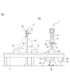
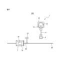
- FIG. 1 is a front view showing a schematic overall configuration of a first embodiment of a robot system according to the present embodiment.
- FIG. 2 is a plan view of the robot system shown in FIG.
- FIG. 3 is a functional block diagram of the robot system shown in FIG.
- FIG. 4 is a diagram for explaining an example of the visual sensor in the functional block diagram shown in FIG.
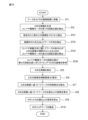
- FIG. 5 is a flowchart for explaining an example of a control process by the robot control device (control device) in the functional block diagram shown in FIG.
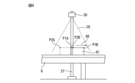
- FIG. 6 is a diagram for explaining how three-dimensional information of a workpiece is generated.
- FIG. 7 is a diagram for explaining an example of processing by the two-dimensional image processing range limiting unit in the functional block diagram shown in FIG. FIG.
- FIG. 8 is a diagram for explaining an example of a process performed by the two-dimensional image acquisition unit in the functional block diagram shown in FIG.
- FIG. 9 is a diagram for explaining another example of the process performed by the two-dimensional image processing range limiting unit in the functional block diagram shown in FIG.
- FIG. 10 is a flowchart for explaining another example of the control process by the robot control device (control device) in the functional block diagram shown in FIG.
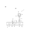
- FIG. 11 is a plan view that shows a schematic overall configuration of a second example of a robot system according to this embodiment.
- FIG. 1 is a front view showing a schematic overall configuration of a first embodiment of a robot system according to this embodiment
- FIG. 2 is a plan view of the robot system shown in FIG. 1.
- reference numeral 100 indicates the robot system of the first embodiment, with 1 indicating a robot, 2 indicating a hand, 3 indicating an imaging device, 6 indicating a conveyor, and 81 indicating a workpiece (object).
- the robot system 100 includes a robot 1 equipped with a hand 2, a conveyor 6, and an imaging device 3.
- the robot 1 includes a base 14 fixed to a mounting surface, a swivel base 13 that rotates relative to the base 14, a lower arm 12 rotatably supported on the swivel base 13, an upper arm 11 rotatably supported on the lower arm 12, and a wrist 15 rotatably supported on the end of the upper arm 11.
- the upper arm 11 rotates around a rotation axis parallel to the direction in which the upper arm 11 extends, and a rotatably formed flange 16 is provided at the end of the wrist 15.
- the robot 1 is an articulated robot having multiple joints, but is not limited to this form and any robot that can control various work tools can be applied.
- the workpiece 81 is depicted as a rectangular parallelepiped cardboard box as an example, but the workpiece 81 is of course not limited to a cardboard box.
- the hand 2 is a work tool capable of gripping the workpiece 81, and is configured to, for example, grip the workpiece 81 by suction using a number of suction pads 2a.
- the hand 2 is fixed to the flange 16 of the wrist 15, but any work tool can be used as the work tool attached to the robot 1.
- the conveyor 6 is an example of a moving device that transports the workpiece 81, and transports the workpiece 81 in a predetermined direction by rotating the circular belt 6a. That is, the conveyor 6 moves the workpiece 81 horizontally as shown by the arrow 86, and transports the workpiece 81 to a position where the robot 1 can change its position and attitude and the hand 2 can grasp the workpiece 81.
- the imaging device 3 includes a two-dimensional sensor (visual sensor 30) that captures a two-dimensional image of the workpiece 81, and a three-dimensional sensor (visual sensor 30) that acquires three-dimensional information on the surface of the workpiece 81. That is, based on the output of the visual sensor 30, it is possible to capture a two-dimensional image of the workpiece 81 being transported by the conveyor 6 and acquire three-dimensional information (three-dimensional point cloud data, three-dimensional position information) on the surface of the workpiece 81.
- reference numeral 24 denotes a conveyor drive motor that drives the circular belt 6a of the conveyor 6, and 25 denotes a position detector such as an encoder.
- An example of the visual sensor 30 will be described in detail later with reference to FIG. 4.
- the visual sensor 30 is supported by a support member 37 and is positioned so that it can capture an image of the workpiece 81 being transported by the conveyor 6.
- the visual sensor 30 is positioned upstream of the robot 1 in the direction in which the workpiece 81 is transported.
- a world coordinate system 76 is set in the robot system 100 as a reference coordinate system, and the origin of the world coordinate system 76 is set, for example, on the base part 14 of the robot 1. This ensures that the position and orientation of the world coordinate system 76 do not change even if the position and posture of the robot 1 change.
- the world coordinate system 76 has mutually orthogonal X-axis, Y-axis, and Z-axis as its coordinate axes, and the W-axis, P-axis, and R-axis are set as coordinate axes around the X-axis, Y-axis, and Z-axis.
- a tool coordinate system 77 is set with an origin set at an arbitrary position of the work tool, and the origin of the tool coordinate system 77 is set at the tool tip point of the hand 2.
- the position and attitude of the tool coordinate system 77 change, and for example, the position of the robot 1 corresponds to the position of the tool tip point, and the attitude of the robot 1 corresponds to the orientation of the tool coordinate system 77 relative to the world coordinate system 76.
- a sensor coordinate system 78 is set corresponding to the visual sensor 30, and the origin of the sensor coordinate system 78 is a coordinate system fixed to the visual sensor 30.
- the coordinate values in the sensor coordinate system 78 can be converted to coordinate values in the world coordinate system 76 based on the position and attitude of the sensor coordinate system 78 relative to the world coordinate system 76.
- FIG. 3 is a functional block diagram of the robot system shown in FIG. 1, and the robot system 100 further includes a robot control device (control device) 4 and a conveyor control device 5.
- the robot 1 includes a plurality of robot drive motors 22 that change the position and posture of the robot 1, and a position detector 23 such as an encoder attached to each robot drive motor 22.
- the hand 2 includes, for example, a pump 21 for reducing the pressure inside the suction pad 2a to suction the workpiece 81.
- the robot control device 4 includes a memory unit 42, an operation control unit 43, a hand driving unit 44, a robot driving unit 45, a display 46, and an image processing unit 47.
- the operation control unit 43 and the image processing unit 47 are composed of a microprocessor (MPU) that functions as an arithmetic processing device, and perform various processes by sending and receiving data to and from the memory unit 42, which includes a RAM (Random Access Memory), a ROM (Read Only Memory), and a flash memory.
- the operation program 41 that controls the robot 1, the hand 2, the conveyor 6, etc. is stored in the memory unit 42, and is executed by the arithmetic processing device (the operation control unit 43, the image processing unit 47, etc.).
- the operation control unit 43 outputs operation commands according to the operation program 41 to the hand driving unit 44 and the robot driving unit 45, and controls the hand 2 and the robot 1.
- the operation control unit 43 also outputs operation commands according to the operation program 41 to the image processing unit 47, and controls the acquisition of two-dimensional images based on the output of the visual sensor 30, the generation of three-dimensional information, image processing, and the like.
- the display unit 46 is, for example, composed of a liquid crystal display panel, and displays information relating to the control of the hand 2, the robot 1, and the conveyor 6, and the like.
- the conveyor control device 5 includes a memory unit 52, an operation control unit 53, and a conveyor drive unit 54, and controls the conveyor 6 based on commands from the robot control device 4 to transport the workpiece 81 to a predetermined position.
- the conveyor 6 is configured to include a conveyor drive motor 24 and a position detector 25.
- the position detector 25 can be configured, for example, as an encoder (rotary encoder) attached to the output shaft of the conveyor drive motor 24, and the approximate position of the workpiece 81 transported by the conveyor 6 can be recognized based on the output of this encoder.
- the position detector 25 is not limited to an encoder, and for example, a photoelectric sensor or the like can also be used.
- the image processing unit 47 includes a three-dimensional information generation unit 61, a two-dimensional image acquisition unit 62, a movement control unit 63, a two-dimensional image processing range limiting unit 64, a characteristic part detection unit 65, and a calculation unit 66.
- the three-dimensional information generation unit 61 generates three-dimensional information based on the output of the three-dimensional sensor, and the two-dimensional image acquisition unit 62 acquires a two-dimensional image based on the output of the two-dimensional sensor.
- the movement control unit 63 corrects the relative position of the three-dimensional information with respect to the two-dimensional image, and the two-dimensional image processing range limiting unit 64 limits the two-dimensional image to a narrower range from the two-dimensional image acquired by the two-dimensional image acquisition unit 62, and outputs the limited two-dimensional image as the processing range.
- the characteristic part detection unit 65 detects predetermined characteristic parts of the workpiece 81, and the calculation unit 66 calculates the position and posture of the robot 1 based on the position and posture of the workpiece 81.
- the image processing unit 47 does not need to be built into the robot control device 4, but may be provided separately outside the robot control device 4, and the conveyor control device 5 may also be built into the robot control device 4, allowing for various modifications and variations.
- FIG. 4 is a diagram for explaining an example of a visual sensor in the functional block diagram shown in FIG. 3.
- the visual sensor 30 (imaging device 3) includes a first camera 31, a second camera 32, and a projector 33.
- the first camera 31 and the second camera 32 function as stereo cameras, but each camera 31 or 32 also functions as a two-dimensional camera that captures two-dimensional images.
- any camera equipped with an imaging element such as a CCD (Charge-Coupled Device) sensor or a CMOS (Complementary Metal-Oxide Semiconductor) sensor can be used as the cameras 31 and 32.
- the two cameras 31 and 32 are arranged at a distance from each other at predetermined positions.
- the projector 33 projects a pattern light such as a striped pattern onto the workpiece 81, and the cameras 31, 32 and the projector 33 are arranged inside the housing 34.
- the three-dimensional information generating unit 61 generates three-dimensional information based on the output of the visual sensor 30, for example, the projector 33 projects the pattern light and uses stereo images (two two-dimensional images) from the first camera 31 and the second camera 32.
- the two-dimensional image acquiring unit 62 acquires a two-dimensional image based on the output of the visual sensor 30, for example, the pattern light from the projector 33 is stopped and a two-dimensional image captured by either the first camera 31 or the second camera 32 is used.
- the timing at which the three-dimensional information generating unit 61 processes the output of the visual sensor 30 is different from the timing at which the two-dimensional image acquiring unit 62 acquires the output of the visual sensor 30.
- the visual sensor 30 is equipped with both a dedicated three-dimensional sensor for outputting to the three-dimensional information generating unit 61, such as a TOF (Time Of Flight) type, and a dedicated two-dimensional sensor for outputting to the two-dimensional image acquiring unit 62, it is possible to perform processing without any difference in timing.
- various known three-dimensional sensors and two-dimensional sensors can be used as the visual sensor 30 in addition to the examples mentioned above.
- the three-dimensional information generating unit 61 processes the image acquired by the visual sensor 30 to generate three-dimensional information of the surface of the imaging target as three-dimensional point cloud data (three-dimensional map).
- the three-dimensional information includes, for example, information on the positions of multiple measurement points set on the surface of the imaging target.
- the three-dimensional point cloud data represents the position of the surface of the imaging target using a collection of coordinate values (x, y, z) of the measurement points set on the surface of the imaging target.
- the three-dimensional information generating unit 61 sets a plurality of measurement points on the surface of the imaging target within the imaging range 35 of the visual sensor 30, and these measurement points can be set for each pixel of the two-dimensional image of the camera 31 or the camera 32.
- the three-dimensional information generating unit 61 can also calculate the distance from the visual sensor 30 to each measurement point based on the parallax of the two-dimensional images captured by the two cameras 31 and 32.
- the three-dimensional information generating unit 61 then calculates the coordinate values of the measurement points in the sensor coordinate system 78 based on the distance from the visual sensor 30 to each measurement point.
- the coordinate values of the sensor coordinate system 78 can be converted to coordinate values of the world coordinate system 76 based on the position and orientation of the visual sensor 30.
- the three-dimensional information generating unit 61 generates three-dimensional point cloud data (three-dimensional information) including the coordinate values of the plurality of measurement points.
- the movement control unit 63 acquires the output of the position detector 25 of the conveyor 6, and calculates the actual amount of movement of the workpiece 81 from the time the stereo image was captured to the time the two-dimensional image was captured in order to generate three-dimensional information.
- the movement control unit 63 then performs control to move the three-dimensional information so as to correspond to the two-dimensional image in a predetermined coordinate system in accordance with the amount of movement of the workpiece 81.
- This control makes it possible to superimpose at least a portion of the three-dimensional information of the workpiece 81 and the two-dimensional image of the workpiece 81 in the above coordinate system. In other words, it is possible to generate three-dimensional information and two-dimensional images equivalent to the three-dimensional information and two-dimensional image captured at the same time.
- FIG. 5 is a flow chart for explaining an example of control processing by the robot control device (control device) in the functional block diagram shown in FIG. 3.
- the conveyor control device 5 controls the conveyor 6 to move the workpiece 81 in the direction shown by the arrow 86 in FIG. 6 so that the workpiece 81 is included in the imaging range 35 of the visual sensor 30. Whether or not the workpiece 81 is included in the imaging range 35 can be recognized based on the output of the position detector 25.
- step ST2 the process proceeds to step ST2, where the three-dimensional information generating unit 61 generates three-dimensional information based on the output of the visual sensor 30 (e.g., a stereo image).
- the position detector 25 detects the first rotational position of the conveyor drive motor 24 and outputs it to the conveyor control device 5.
- step ST3 the two-dimensional image acquiring unit 62 acquires a two-dimensional image based on the output of the visual sensor 30 (e.g., a two-dimensional image from the first camera 31).
- the position detector 25 detects the second rotational position of the conveyor drive motor 24 and outputs it to the conveyor control device 5.
- a sensor e.g., a photoelectric sensor
- the rotational position (first and second rotational positions) of the position detector 25 may be detected based on the output of the sensor.
- the first rotational position and second rotational position output from the position detector 25 may be stored and held in the memory unit 52, for example.
- step ST4 the movement distance of the workpiece 81 on the conveyor 6 is calculated, and the process proceeds to step ST5.
- step ST5 the movement control unit 63 corrects the relative position of the three-dimensional information with respect to the two-dimensional image, and the process proceeds to step ST6.
- step ST6 the two-dimensional image processing range limiting unit 64 calculates (limits) the processing range from the two-dimensional image acquired by the two-dimensional image acquisition unit 62, and the process proceeds to step ST7.
- the processing range limiting process by the two-dimensional image processing range limiting unit 64 will be described in detail later with reference to Figures 6 to 9.
- the characteristic part detection unit 65 detects the characteristic part of the workpiece 81 in the two-dimensional image whose processing range has been limited by the two-dimensional image processing range limiting unit 64.
- a reference image of the top surface of the workpiece 81 is stored in advance in the storage unit 42.
- the reference image may be an image of the top surface of the workpiece 81 actually captured by a two-dimensional camera, or the reference image of the workpiece 81 may be generated based on three-dimensional data obtained by a CAD (Computer Aided Design) device.
- the characteristic part detection unit 65 detects an image of the top surface of the workpiece 81 in the two-dimensional image whose processing range has been limited by the two-dimensional image processing range limiting unit 64 by a method such as template matching using the reference image.
- the control device (robot system) of this embodiment even if the surface of the conveyor 6 (belt 6a) is mesh-like or the like, processing is performed based on a two-dimensional image whose processing range is limited by the two-dimensional image processing range limiting unit 64, so that it is possible to reduce erroneous detection of the workpiece 81, for example. Furthermore, the processing range of the two-dimensional image limited by the two-dimensional image processing range limiting unit 64 has a narrower processing region (area) than the two-dimensional image acquired by the two-dimensional image acquisition unit 62, making it possible to speed up processing.
- step ST8 the calculation unit 66 calculates the position and orientation of the workpiece 81.
- the position of the workpiece 81 can be set to, for example, the center of gravity of the rectangle on the top surface of the workpiece 81, a specific position, or the position of an end, and the orientation of the workpiece can be set to, for example, the normal direction of the top surface of the workpiece 81.
- the calculation unit 66 extracts measurement points located in an area overlapping the image 72a, and calculates the position and orientation of the workpiece 81 based on the coordinate values of the multiple measurement points.
- step ST9 the calculation unit 66 calculates the position and orientation of the robot 1 based on the position and orientation of the workpiece 81. That is, the calculation unit 66 calculates the position and orientation of the workpiece 81 when the workpiece 81 is moved by the conveyor 6 to a position where it is grasped by the hand 2, and calculates the position and orientation of the robot 1 based on the position and orientation of the workpiece 81 at that time.
- step ST10 the calculation unit 66 sends a command to the operation control unit 43 to drive the robot 1 and the hand 2.
- the operation control unit 43 drives the robot 1 and the hand 2 based on the command from the calculation unit 66, and the robot 1 (hand 2) grasps and transports the workpiece 81, and an example of the control process by the robot control device of this first embodiment ends (END).
- the two-dimensional image processing range limiting unit 64 limits the processing range from the two-dimensional image acquired by the two-dimensional image acquiring unit 62, and thus performs detection processing etc. based on the two-dimensional image that is actually required, thereby reducing erroneous detection etc. of the workpiece 81. Furthermore, since the processing range of the two-dimensional image limited by the two-dimensional image processing range limiting unit 64 has a smaller area than the two-dimensional image acquired by the two-dimensional image acquiring unit 62, processing can be speeded up.
- FIG. 6 is a diagram for explaining how three-dimensional information (three-dimensional point cloud data) of a workpiece is generated
- FIG. 7 is a diagram for explaining an example of processing by the two-dimensional image processing range limiting unit in the functional block diagram shown in FIG. 3.
- reference numeral 71 indicates a two-dimensional image (measurement area) acquired by the two-dimensional image acquisition unit 62
- 71a indicates the image area of the workpiece 81
- 71b indicates the image areas (measurement points PX) of both ends of the belt 6a of the conveyor 6
- 71c indicates the image area of the transport portion of the belt 6a
- 71d indicates the image area of the floor surface on which the conveyor 6 is installed.
- reference numeral 91 indicates the processing range limited (calculated) by the two-dimensional image processing range limiting unit 64, and 91a to 91c indicate margins.
- margin 91c is the portion before workpiece 81 arrives, it is considered preferable to set it wider than margin 91a, which is the portion after workpiece 81 arrives. Also, because margin 91b hardly deviates in the direction perpendicular to the movement direction of workpiece 81, it is considered acceptable to set it narrower than margin 91a, which is the portion after workpiece 81 arrives.
- the processing range limiting process by two-dimensional image processing range limiting unit 64 is not limited to the above.
- FIG. 8 is a diagram for explaining an example of processing by the two-dimensional image acquisition unit in the functional block diagram shown in FIG. 3.
- the position of the workpiece 81 used to generate the three-dimensional information is indicated by a dashed line.
- the workpiece 81 moves in the direction indicated by the arrow 86 by the conveyor 6, and for example, the first camera 31 of the visual sensor 30 captures a two-dimensional image of the workpiece 81 when the workpiece 81 is transported inside the imaging range 35. That is, the visual sensor 30 can capture a two-dimensional image immediately after capturing an image for generating the three-dimensional information. Alternatively, the visual sensor 30 can capture a two-dimensional image a predetermined time after capturing an image for acquiring the three-dimensional information.
- the movement control unit 63 performs movement control for each measurement point, and the three-dimensional information includes, for example, the coordinate value of measurement point P1A placed on the surface of the workpiece 81.
- the movement control unit 63 processes measurement point P1A in the direction in which the workpiece 81 moves based on the amount of movement of the workpiece 81, and processes measurement points P1A and P2A to move to measurement points P1B and P2B.
- the movement control unit 63 changes the relative position of the three-dimensional information generated by the three-dimensional information generation unit 61 based on the processing range of the two-dimensional image limited by the two-dimensional image processing range limiting unit 64, for example, in a predetermined coordinate system (for example, the sensor coordinate system 78 shown in FIG. 1).
- FIG. 9 is a diagram for explaining another example of processing by the two-dimensional image processing range limiting unit in the functional block diagram shown in FIG. 3.
- the processing range limiting process by the two-dimensional image processing range limiting unit 64 described with reference to FIG. 7 limits the processing range 91 with margins 91a to 91c provided around the image area 71a of the workpiece 81, but the processing range limiting process by the two-dimensional image processing range limiting unit 64 described with reference to FIG. 9 limits the processing range to match the image area of the workpiece 81 in the two-dimensional image acquired by the two-dimensional image acquisition unit 62.
- FIG. 9 is a diagram for explaining another example of processing by the two-dimensional image processing range limiting unit in the functional block diagram shown in FIG. 3.
- the processing range limiting process by the two-dimensional image processing range limiting unit 64 described with reference to FIG. 7 limits the processing range 91 with margins 91a to 91c provided around the image area 71a of the workpiece 81, but the processing range limiting process by the
- reference symbol MK indicates a label such as a two-dimensional code attached to the top surface of the workpiece 81, for example, a cardboard box, and 79 indicates the image coordinate system.
- Reference symbols 72, 72a, 72b, and 72c indicate parts corresponding to 71, 71a, 71b, and 71c in FIG. 7 described above, and 87 indicates the direction in which the workpiece 81 moves.
- the two-dimensional image processing range limiting unit 64 limits the image area 72a (71a) of the workpiece 81 in the two-dimensional image 72 acquired by the two-dimensional image acquisition unit 62 as the processing range for actually performing processing. That is, for example, when reading a label MK affixed to the top surface of a workpiece 81, it is conceivable that the label MK can be read even if the processing range limited by the two-dimensional image processing range limiting unit 64 is the image area of the workpiece 81.
- three-dimensional information (three-dimensional position information) at the timing when the two-dimensional image acquisition unit 62 acquires the two-dimensional image (when the visual sensor 30 captures the two-dimensional image) can be obtained.
- the distance [mm] from the visual sensor 30 to the top surface of the cardboard box (workpiece 81) can be obtained, and the obtained X, Y position information [mm] of the cardboard box can be converted into position information [pixel] on the two-dimensional image.
- the four corners (x1, y1), (x2, y1), (x1, y2), (x2, y2) of the cardboard box (workpiece 81) are converted into the four corners (h1, w1), (h2, w1), (h1, w2), (h2, w2) on the two-dimensional image acquired by the two-dimensional image acquisition unit 62, and the four corners on this two-dimensional image can be set as the processing range limited by the two-dimensional image processing range limiting unit 64 to detect the label MK.
- control device control method
- this embodiment is not limited to application to a robot system that grasps a moving workpiece and performs work, or a robot system that detects a label affixed to the top surface of a moving workpiece and performs work, but can be widely applied to robot systems that perform various processes on a moving workpiece.
- FIG. 10 is a flow chart for explaining another example of the control process by the robot control device (control device) in the functional block diagram shown in FIG. 3.
- the control process shown in FIG. 10 corresponds to the control process described with reference to FIG. 5, with the processes of steps ST3 and ST4 replaced with ST31 to ST34.
- the conveyor control device 5 controls the conveyor 6 to move the workpiece 81 in the direction shown by the arrow 86 in FIG. 6, and the process proceeds to step ST2.
- step ST2 the three-dimensional information generating unit 61 generates three-dimensional information based on the output of the visual sensor 30, and the position detector 25 detects the first rotational position of the conveyor drive motor 24 and outputs it to the conveyor control device 5, and then the process proceeds to step ST31.
- step ST31 the specified height (Z: vertical direction relative to the XY plane of the two-dimensional image) range is read from memory (storage unit 42), and the process proceeds to step ST32, where the contour (current position) of the workpiece 81 is detected from three-dimensional points (three-dimensional point cloud data) within the range (imaging range 35 in FIG. 8).
- the contour of the workpiece 81 in the XY plane can be defined, for example, as a circumscribed rectangle including points (x, y) obtained by projecting the three-dimensional points onto the XY plane.
- the three-dimensional points read from memory and processed can be, for example, data of a predetermined range in the height (Z) direction relative to the surface of the belt 6a of the conveyor 6.
- This height range can be set appropriately in advance, for example, depending on the type and shape of the workpiece 81 handled by the robot system 100. Specifically, if the shape of the workpiece 81 handled by the robot system 100 is known in advance, for example, the tallest workpiece 81max and the shortest workpiece 81min among the workpieces 81 handled can be positioned within the imaging range 35 and detected, making it possible to set the height range without directly specifying a numerical value.
- step ST33 calculate the second rotation position of the conveyor drive motor 24 when the center of the outline of the workpiece 81 becomes the center of the field of view of the two-dimensional image in relation to the moving direction of the conveyor 6, and proceed to step ST34.
- step ST34 obtain a two-dimensional image at the timing when the rotation position of the conveyor drive motor 24 reaches the second rotation position, proceed to step ST5, and correct the three-dimensional information. Note that the processing of the subsequent steps ST6 to ST10 is the same as that described with reference to FIG. 5, and the description thereof will be omitted.
- the two-dimensional image processing range limiting unit 64 can limit the processing range in the two-dimensional image obtained by the two-dimensional image obtaining unit 62, for example, based on the current position of the workpiece 81 in the three-dimensional information generated by the three-dimensional information generating unit 61.
- the control processing by the robot control device is not limited to the above example, and it goes without saying that various changes and modifications are possible.
- FIG. 11 is a plan view showing a schematic overall configuration of a second embodiment of the robot system according to this embodiment.
- a transport vehicle 7 is used in place of the conveyor 6 in the robot system 100 of the first embodiment. That is, in the robot system 200 of the second embodiment, the transport vehicle 7 is an example of a moving device that transports a workpiece 81, and the workpiece 81 is placed on a mounting table 7a and automatically moves, for example, along a tape 39 affixed to the floor surface. That is, the transport vehicle 7 includes a sensor that detects the tape 39, and automatically moves along the tape 39 while detecting the tape 39 with the sensor.
- a visual sensor 30 fixed to a support member 37 is disposed above the path along which the transport vehicle 7 moves.
- This visual sensor 30 is similar to that in the robot system 100 of the first embodiment described above, and is disposed in a position where it can capture an image of the workpiece 81 being moved by the transport vehicle 7.
- the transport vehicle 7 includes a drive motor for driving the wheels, and a position detector equivalent to the position detector 25 attached to the conveyor drive motor 24 of the conveyor 6 is attached to the output shaft of the drive motor.
- the position of the mounting platform 7a can be determined, for example, by the position of a set point set at an arbitrary position on the transport vehicle 7, and for example, the control device 4 shown in FIG. 3 can recognize the position of the mounting platform 7a (workpiece 81).
- the conveyor 6 and the transport vehicle 7 can be used as the moving device for transporting the workpiece 81, but are not limited to these, and for example, a robot for transporting the workpiece 81 can also be used.
- the imaging device 3 visual sensor 30
- various devices can be used as long as they can acquire and synchronize two-dimensional images and three-dimensional information (three-dimensional point cloud data) by moving the three-dimensional information in a predetermined coordinate system. In this way, according to this embodiment, it is possible to provide a control device, robot system, and control method that are highly accurate and capable of high-speed processing.
- a control device (4) that receives an output from a visual sensor (30) that captures an image of a moving work (81) and controls processing of the work (81), A two-dimensional image acquisition unit (62) that acquires a two-dimensional image including the work (81) based on an output of the visual sensor (30); A three-dimensional information generating unit (61) that generates three-dimensional information including the work (81) based on an output of the visual sensor (30); a two-dimensional image processing range limiting unit (64) that limits a processing range in the acquired two-dimensional image; and a movement control unit (63) for changing a relative position of the three-dimensional information based on a limited processing range of the two-dimensional image in a predetermined coordinate system.
- the two-dimensional image processing range limiting unit (64) limits a processing range in the acquired two-dimensional image based on a current position of the workpiece (81) in the generated three-dimensional information. 2.
- the two-dimensional image processing range limiting unit (64) limits a processing range by adding a margin to an image area of the work (81) in the acquired two-dimensional image.
- the two-dimensional image processing range limiting unit (64) limits the processing range in the acquired two-dimensional image so that a front margin in a direction in which the workpiece (81) moves is wider than a rear margin in a direction in which the workpiece (81) moves. 4.
- the two-dimensional image processing range limiting unit (64) limits the processing range in the acquired two-dimensional image so that the margins on both sides of the direction in which the workpiece (81) moves are narrower than the rear margin of the direction in which the workpiece (81) moves. 5.
- the two-dimensional image processing range limiting unit (64) limits a processing range in the acquired two-dimensional image so as to coincide with an image area of the work (81). 3.
- an operation control unit is provided that controls processing of the work (81) based on the limited processing range of the two-dimensional image and the three-dimensional information. 7. The control device according to claim 1 .
- the movement control unit calculates a movement amount of the work (81) based on a first position of the work (81) when the output of the visual sensor (30) is used to generate the three-dimensional information and a second position of the work (81) when the output of the visual sensor (30) is used to acquire the two-dimensional image, and moves the three-dimensional information so as to correspond to the movement amount of the work (81) in the coordinate system, thereby moving the three-dimensional information within a limited processing range of the two-dimensional image.
- the control device according to claim 1 .
- the moving device is a conveyor (6) or a transport vehicle (7) that carries and moves the work (81). 10.
- the visual sensor (30) is a sensor capable of acquiring two-dimensional images and three-dimensional information. 11. The robot system according to claim 9 or 10.
- Robot 2 Hand 3 Imaging device 4 Robot control device (control device) 5 Conveyor control device 6 Conveyor (moving device) 7 Transport vehicle (mobile device) Description of the Reference Signs 23, 25 Position detector 24 Conveyor drive motor 26 Conveyor drive device 30 Visual sensor 31 First camera 32 Second camera 33 Projector 41 Operation program 42, 52 Memory unit 43, 53 Operation control unit 44 Hand drive unit 45 Robot drive unit 46 Display 47 Image processing unit 54 Conveyor drive unit 61 Three-dimensional information generation unit 62 Two-dimensional image acquisition unit 63 Movement control unit 64 Two-dimensional image processing range limiting unit 65 Characteristic portion detection unit 66 Calculation unit 71 Measurement area 81 Workpiece 91 Processing range 91a, 91b, 91c Margin 100, 200 Robot system
Landscapes
- Engineering & Computer Science (AREA)
- Physics & Mathematics (AREA)
- General Physics & Mathematics (AREA)
- Theoretical Computer Science (AREA)
- Multimedia (AREA)
- Computer Vision & Pattern Recognition (AREA)
- Manipulator (AREA)
Abstract
La présente invention concerne un dispositif de commande qui est capable d'effectuer un traitement à grande vitesse avec une précision élevée. Ce dispositif de commande reçoit une sortie d'un capteur visuel qui effectue une capture d'image d'une pièce à travailler qui se déplace, et commande un traitement effectué sur la pièce à travailler. Le dispositif de commande comprend une unité d'acquisition d'image bidimensionnelle, une unité de génération d'informations tridimensionnelles, une unité de limitation de plage de traitement d'images bidimensionnelles et une unité de commande de mouvement. L'unité d'acquisition d'image bidimensionnelle acquiert une image bidimensionnelle comprenant la pièce à travailler, sur la base de la sortie du capteur visuel, et l'unité de génération d'informations tridimensionnelles génère des informations tridimensionnelles comprenant la pièce à travailler, sur la base de la sortie du capteur visuel. L'unité de limitation de plage de traitement d'image bidimensionnelle limite la plage de traitement dans l'image bidimensionnelle acquise, et l'unité de commande de mouvement modifie une position relative des informations tridimensionnelles sur la base de la plage de traitement limitée de l'image bidimensionnelle, dans un système de coordonnées qui est défini à l'avance.
Priority Applications (3)
| Application Number | Priority Date | Filing Date | Title |
|---|---|---|---|
| PCT/JP2023/030177 WO2025041269A1 (fr) | 2023-08-22 | 2023-08-22 | Dispositif de commande, système de robot et procédé de commande |
| CN202380101342.XA CN121693759A (zh) | 2023-08-22 | 2023-08-22 | 控制装置、机器人系统以及控制方法 |
| TW113127331A TW202521299A (zh) | 2023-08-22 | 2024-07-22 | 控制裝置、機器人系統及控制方法 |
Applications Claiming Priority (1)
| Application Number | Priority Date | Filing Date | Title |
|---|---|---|---|
| PCT/JP2023/030177 WO2025041269A1 (fr) | 2023-08-22 | 2023-08-22 | Dispositif de commande, système de robot et procédé de commande |
Publications (1)
| Publication Number | Publication Date |
|---|---|
| WO2025041269A1 true WO2025041269A1 (fr) | 2025-02-27 |
Family
ID=94731542
Family Applications (1)
| Application Number | Title | Priority Date | Filing Date |
|---|---|---|---|
| PCT/JP2023/030177 Pending WO2025041269A1 (fr) | 2023-08-22 | 2023-08-22 | Dispositif de commande, système de robot et procédé de commande |
Country Status (3)
| Country | Link |
|---|---|
| CN (1) | CN121693759A (fr) |
| TW (1) | TW202521299A (fr) |
| WO (1) | WO2025041269A1 (fr) |
Citations (3)
| Publication number | Priority date | Publication date | Assignee | Title |
|---|---|---|---|---|
| JP2013101045A (ja) * | 2011-11-08 | 2013-05-23 | Fanuc Ltd | 物品の3次元位置姿勢の認識装置及び認識方法 |
| WO2015049723A1 (fr) * | 2013-10-01 | 2015-04-09 | 富士機械製造株式会社 | Machine d'assemblage |
| WO2021256437A1 (fr) * | 2020-06-18 | 2021-12-23 | ファナック株式会社 | Dispositif d'imagerie pour acquérir des informations tridimensionnelles d'une surface de pièce à travailler et image bidimensionnelle d'une pièce à travailler |
-
2023
- 2023-08-22 WO PCT/JP2023/030177 patent/WO2025041269A1/fr active Pending
- 2023-08-22 CN CN202380101342.XA patent/CN121693759A/zh active Pending
-
2024
- 2024-07-22 TW TW113127331A patent/TW202521299A/zh unknown
Patent Citations (3)
| Publication number | Priority date | Publication date | Assignee | Title |
|---|---|---|---|---|
| JP2013101045A (ja) * | 2011-11-08 | 2013-05-23 | Fanuc Ltd | 物品の3次元位置姿勢の認識装置及び認識方法 |
| WO2015049723A1 (fr) * | 2013-10-01 | 2015-04-09 | 富士機械製造株式会社 | Machine d'assemblage |
| WO2021256437A1 (fr) * | 2020-06-18 | 2021-12-23 | ファナック株式会社 | Dispositif d'imagerie pour acquérir des informations tridimensionnelles d'une surface de pièce à travailler et image bidimensionnelle d'une pièce à travailler |
Also Published As
| Publication number | Publication date |
|---|---|
| CN121693759A (zh) | 2026-03-17 |
| TW202521299A (zh) | 2025-06-01 |
Similar Documents
| Publication | Publication Date | Title |
|---|---|---|
| JP6180087B2 (ja) | 情報処理装置及び情報処理方法 | |
| EP2082850B1 (fr) | Dispositif de génération de programme de robot de traitement | |
| US9519736B2 (en) | Data generation device for vision sensor and detection simulation system | |
| JP2019113895A (ja) | ワークを撮像する視覚センサを備える撮像装置 | |
| CN112297004B (zh) | 对机器人的位置进行控制的机器人装置的控制装置 | |
| JP7000361B2 (ja) | 追随ロボットおよび作業ロボットシステム | |
| JP2023108062A (ja) | 制御装置、ロボット装置、制御方法、およびプログラム | |
| CN107150032A (zh) | 一种基于多图像获取设备的工件识别与分拣装置和方法 | |
| JP2019188508A (ja) | 作業ロボットシステムおよび作業ロボット | |
| JP2016147330A (ja) | 物体認識に基づく制御装置 | |
| CN115605329B (zh) | 随动机器人 | |
| CN107614195A (zh) | 齿轮机构的组装装置及组装方法 | |
| JP5509859B2 (ja) | ロボット制御装置及び方法 | |
| JP7568721B2 (ja) | ワークの表面の3次元情報およびワークの2次元画像を取得する撮像装置および制御装置 | |
| TWI910344B (zh) | 根據由視覺感測器所拍攝之圖像來算出三維之位置的攝像裝置 | |
| CN116867619B (zh) | 示教装置 | |
| JP7477633B2 (ja) | ロボットシステム | |
| JP7704852B2 (ja) | 生産システム | |
| WO2025041269A1 (fr) | Dispositif de commande, système de robot et procédé de commande | |
| JPH09222913A (ja) | ロボットの教示位置補正装置 | |
| JP2022530589A (ja) | ロボット搭載移動装置、システム及び工作機械 | |
| JP7846140B2 (ja) | 3次元センサを備えるロボット装置およびロボット装置の制御方法 | |
| JP7221409B2 (ja) | 高さ測定装置 | |
| JP2023051620A (ja) | トラッキングシステムの制御方法およびトラッキングシステム | |
| TW202419237A (zh) | 工件取出裝置、工件取出方法及控制裝置 |
Legal Events
| Date | Code | Title | Description |
|---|---|---|---|
| 121 | Ep: the epo has been informed by wipo that ep was designated in this application |
Ref document number: 23949730 Country of ref document: EP Kind code of ref document: A1 |
|
| ENP | Entry into the national phase |
Ref document number: 2025541220 Country of ref document: JP Kind code of ref document: A |