WO2025041269A1 - 制御装置、ロボットシステムおよび制御方法 - Google Patents
制御装置、ロボットシステムおよび制御方法 Download PDFInfo
- Publication number
- WO2025041269A1 WO2025041269A1 PCT/JP2023/030177 JP2023030177W WO2025041269A1 WO 2025041269 A1 WO2025041269 A1 WO 2025041269A1 JP 2023030177 W JP2023030177 W JP 2023030177W WO 2025041269 A1 WO2025041269 A1 WO 2025041269A1
- Authority
- WO
- WIPO (PCT)
- Prior art keywords
- workpiece
- dimensional image
- dimensional
- processing range
- control device
- Prior art date
- Legal status (The legal status is an assumption and is not a legal conclusion. Google has not performed a legal analysis and makes no representation as to the accuracy of the status listed.)
- Pending
Links
Images


Classifications
-
- G—PHYSICS
- G06—COMPUTING OR CALCULATING; COUNTING
- G06T—IMAGE DATA PROCESSING OR GENERATION, IN GENERAL
- G06T7/00—Image analysis
-
- G—PHYSICS
- G06—COMPUTING OR CALCULATING; COUNTING
- G06V—IMAGE OR VIDEO RECOGNITION OR UNDERSTANDING
- G06V10/00—Arrangements for image or video recognition or understanding
- G06V10/20—Image preprocessing
- G06V10/24—Aligning, centring, orientation detection or correction of the image
-
- G—PHYSICS
- G06—COMPUTING OR CALCULATING; COUNTING
- G06V—IMAGE OR VIDEO RECOGNITION OR UNDERSTANDING
- G06V10/00—Arrangements for image or video recognition or understanding
- G06V10/20—Image preprocessing
- G06V10/25—Determination of region of interest [ROI] or a volume of interest [VOI]
Definitions
- This disclosure relates to a control device, a robot system, and a control method.
- a control device robot control device
- a control device that detects the surface shape and position of a workpiece (target object) based on an image captured by a visual sensor (imaging device) and causes a robot to perform a specified task on the workpiece.
- the visual sensor used is a two-dimensional sensor that captures a two-dimensional image of the workpiece, or a three-dimensional sensor that measures three-dimensional information such as the distance from the visual sensor to the workpiece.
- robot systems have been put into practical use in which a robot equipped with a work tool (end effector) is controlled by the above-mentioned control device to perform a specified task on a moving workpiece.
- the control device calculates the position and orientation of the workpiece based on two-dimensional images and three-dimensional information acquired from the output of a visual sensor, and controls the robot's hand (work tool) to control an operation such as gripping the workpiece.
- the movement (transport) of the workpiece is performed, for example, by a conveyor or a transport vehicle.
- robot systems have been put into practical use that use two-dimensional images obtained from the output of a two-dimensional sensor and three-dimensional information generated from the output of a three-dimensional sensor to control a robot to perform a specified task on a moving workpiece.
- a control device that receives the output of a visual sensor that captures an image of a moving workpiece and controls processing of the workpiece, the control device including a two-dimensional image acquisition unit, a three-dimensional information generation unit, a two-dimensional image processing range limiting unit, and a movement control unit.
- the two-dimensional image acquisition unit acquires a two-dimensional image including the workpiece based on the output of the visual sensor, and the three-dimensional information generation unit generates three-dimensional information including the workpiece based on the output of the visual sensor.
- the two-dimensional image processing range limiting unit limits the processing range in the acquired two-dimensional image, and the movement control unit changes the relative position of the three-dimensional information based on the limited processing range of the two-dimensional image in a predetermined coordinate system.
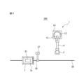
- FIG. 1 is a front view showing a schematic overall configuration of a first embodiment of a robot system according to the present embodiment.
- FIG. 2 is a plan view of the robot system shown in FIG.
- FIG. 3 is a functional block diagram of the robot system shown in FIG.
- FIG. 4 is a diagram for explaining an example of the visual sensor in the functional block diagram shown in FIG.
- FIG. 5 is a flowchart for explaining an example of a control process by the robot control device (control device) in the functional block diagram shown in FIG.
- FIG. 6 is a diagram for explaining how three-dimensional information of a workpiece is generated.
- FIG. 7 is a diagram for explaining an example of processing by the two-dimensional image processing range limiting unit in the functional block diagram shown in FIG. FIG.
- FIG. 8 is a diagram for explaining an example of a process performed by the two-dimensional image acquisition unit in the functional block diagram shown in FIG.
- FIG. 9 is a diagram for explaining another example of the process performed by the two-dimensional image processing range limiting unit in the functional block diagram shown in FIG.
- FIG. 10 is a flowchart for explaining another example of the control process by the robot control device (control device) in the functional block diagram shown in FIG.
- FIG. 11 is a plan view that shows a schematic overall configuration of a second example of a robot system according to this embodiment.
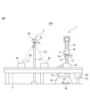
- FIG. 1 is a front view showing a schematic overall configuration of a first embodiment of a robot system according to this embodiment
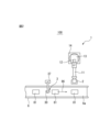
- FIG. 2 is a plan view of the robot system shown in FIG. 1.
- reference numeral 100 indicates the robot system of the first embodiment, with 1 indicating a robot, 2 indicating a hand, 3 indicating an imaging device, 6 indicating a conveyor, and 81 indicating a workpiece (object).
- the robot system 100 includes a robot 1 equipped with a hand 2, a conveyor 6, and an imaging device 3.
- the robot 1 includes a base 14 fixed to a mounting surface, a swivel base 13 that rotates relative to the base 14, a lower arm 12 rotatably supported on the swivel base 13, an upper arm 11 rotatably supported on the lower arm 12, and a wrist 15 rotatably supported on the end of the upper arm 11.
- the upper arm 11 rotates around a rotation axis parallel to the direction in which the upper arm 11 extends, and a rotatably formed flange 16 is provided at the end of the wrist 15.
- the robot 1 is an articulated robot having multiple joints, but is not limited to this form and any robot that can control various work tools can be applied.
- the workpiece 81 is depicted as a rectangular parallelepiped cardboard box as an example, but the workpiece 81 is of course not limited to a cardboard box.
- the hand 2 is a work tool capable of gripping the workpiece 81, and is configured to, for example, grip the workpiece 81 by suction using a number of suction pads 2a.
- the hand 2 is fixed to the flange 16 of the wrist 15, but any work tool can be used as the work tool attached to the robot 1.
- the conveyor 6 is an example of a moving device that transports the workpiece 81, and transports the workpiece 81 in a predetermined direction by rotating the circular belt 6a. That is, the conveyor 6 moves the workpiece 81 horizontally as shown by the arrow 86, and transports the workpiece 81 to a position where the robot 1 can change its position and attitude and the hand 2 can grasp the workpiece 81.
- the imaging device 3 includes a two-dimensional sensor (visual sensor 30) that captures a two-dimensional image of the workpiece 81, and a three-dimensional sensor (visual sensor 30) that acquires three-dimensional information on the surface of the workpiece 81. That is, based on the output of the visual sensor 30, it is possible to capture a two-dimensional image of the workpiece 81 being transported by the conveyor 6 and acquire three-dimensional information (three-dimensional point cloud data, three-dimensional position information) on the surface of the workpiece 81.
- reference numeral 24 denotes a conveyor drive motor that drives the circular belt 6a of the conveyor 6, and 25 denotes a position detector such as an encoder.
- An example of the visual sensor 30 will be described in detail later with reference to FIG. 4.
- the visual sensor 30 is supported by a support member 37 and is positioned so that it can capture an image of the workpiece 81 being transported by the conveyor 6.
- the visual sensor 30 is positioned upstream of the robot 1 in the direction in which the workpiece 81 is transported.
- a world coordinate system 76 is set in the robot system 100 as a reference coordinate system, and the origin of the world coordinate system 76 is set, for example, on the base part 14 of the robot 1. This ensures that the position and orientation of the world coordinate system 76 do not change even if the position and posture of the robot 1 change.
- the world coordinate system 76 has mutually orthogonal X-axis, Y-axis, and Z-axis as its coordinate axes, and the W-axis, P-axis, and R-axis are set as coordinate axes around the X-axis, Y-axis, and Z-axis.
- a tool coordinate system 77 is set with an origin set at an arbitrary position of the work tool, and the origin of the tool coordinate system 77 is set at the tool tip point of the hand 2.
- the position and attitude of the tool coordinate system 77 change, and for example, the position of the robot 1 corresponds to the position of the tool tip point, and the attitude of the robot 1 corresponds to the orientation of the tool coordinate system 77 relative to the world coordinate system 76.
- a sensor coordinate system 78 is set corresponding to the visual sensor 30, and the origin of the sensor coordinate system 78 is a coordinate system fixed to the visual sensor 30.
- the coordinate values in the sensor coordinate system 78 can be converted to coordinate values in the world coordinate system 76 based on the position and attitude of the sensor coordinate system 78 relative to the world coordinate system 76.
- FIG. 3 is a functional block diagram of the robot system shown in FIG. 1, and the robot system 100 further includes a robot control device (control device) 4 and a conveyor control device 5.
- the robot 1 includes a plurality of robot drive motors 22 that change the position and posture of the robot 1, and a position detector 23 such as an encoder attached to each robot drive motor 22.
- the hand 2 includes, for example, a pump 21 for reducing the pressure inside the suction pad 2a to suction the workpiece 81.
- the robot control device 4 includes a memory unit 42, an operation control unit 43, a hand driving unit 44, a robot driving unit 45, a display 46, and an image processing unit 47.
- the operation control unit 43 and the image processing unit 47 are composed of a microprocessor (MPU) that functions as an arithmetic processing device, and perform various processes by sending and receiving data to and from the memory unit 42, which includes a RAM (Random Access Memory), a ROM (Read Only Memory), and a flash memory.
- the operation program 41 that controls the robot 1, the hand 2, the conveyor 6, etc. is stored in the memory unit 42, and is executed by the arithmetic processing device (the operation control unit 43, the image processing unit 47, etc.).
- the operation control unit 43 outputs operation commands according to the operation program 41 to the hand driving unit 44 and the robot driving unit 45, and controls the hand 2 and the robot 1.
- the operation control unit 43 also outputs operation commands according to the operation program 41 to the image processing unit 47, and controls the acquisition of two-dimensional images based on the output of the visual sensor 30, the generation of three-dimensional information, image processing, and the like.
- the display unit 46 is, for example, composed of a liquid crystal display panel, and displays information relating to the control of the hand 2, the robot 1, and the conveyor 6, and the like.
- the conveyor control device 5 includes a memory unit 52, an operation control unit 53, and a conveyor drive unit 54, and controls the conveyor 6 based on commands from the robot control device 4 to transport the workpiece 81 to a predetermined position.
- the conveyor 6 is configured to include a conveyor drive motor 24 and a position detector 25.
- the position detector 25 can be configured, for example, as an encoder (rotary encoder) attached to the output shaft of the conveyor drive motor 24, and the approximate position of the workpiece 81 transported by the conveyor 6 can be recognized based on the output of this encoder.
- the position detector 25 is not limited to an encoder, and for example, a photoelectric sensor or the like can also be used.
- the image processing unit 47 includes a three-dimensional information generation unit 61, a two-dimensional image acquisition unit 62, a movement control unit 63, a two-dimensional image processing range limiting unit 64, a characteristic part detection unit 65, and a calculation unit 66.
- the three-dimensional information generation unit 61 generates three-dimensional information based on the output of the three-dimensional sensor, and the two-dimensional image acquisition unit 62 acquires a two-dimensional image based on the output of the two-dimensional sensor.
- the movement control unit 63 corrects the relative position of the three-dimensional information with respect to the two-dimensional image, and the two-dimensional image processing range limiting unit 64 limits the two-dimensional image to a narrower range from the two-dimensional image acquired by the two-dimensional image acquisition unit 62, and outputs the limited two-dimensional image as the processing range.
- the characteristic part detection unit 65 detects predetermined characteristic parts of the workpiece 81, and the calculation unit 66 calculates the position and posture of the robot 1 based on the position and posture of the workpiece 81.
- the image processing unit 47 does not need to be built into the robot control device 4, but may be provided separately outside the robot control device 4, and the conveyor control device 5 may also be built into the robot control device 4, allowing for various modifications and variations.
- FIG. 4 is a diagram for explaining an example of a visual sensor in the functional block diagram shown in FIG. 3.
- the visual sensor 30 (imaging device 3) includes a first camera 31, a second camera 32, and a projector 33.
- the first camera 31 and the second camera 32 function as stereo cameras, but each camera 31 or 32 also functions as a two-dimensional camera that captures two-dimensional images.
- any camera equipped with an imaging element such as a CCD (Charge-Coupled Device) sensor or a CMOS (Complementary Metal-Oxide Semiconductor) sensor can be used as the cameras 31 and 32.
- the two cameras 31 and 32 are arranged at a distance from each other at predetermined positions.
- the projector 33 projects a pattern light such as a striped pattern onto the workpiece 81, and the cameras 31, 32 and the projector 33 are arranged inside the housing 34.
- the three-dimensional information generating unit 61 generates three-dimensional information based on the output of the visual sensor 30, for example, the projector 33 projects the pattern light and uses stereo images (two two-dimensional images) from the first camera 31 and the second camera 32.
- the two-dimensional image acquiring unit 62 acquires a two-dimensional image based on the output of the visual sensor 30, for example, the pattern light from the projector 33 is stopped and a two-dimensional image captured by either the first camera 31 or the second camera 32 is used.
- the timing at which the three-dimensional information generating unit 61 processes the output of the visual sensor 30 is different from the timing at which the two-dimensional image acquiring unit 62 acquires the output of the visual sensor 30.
- the visual sensor 30 is equipped with both a dedicated three-dimensional sensor for outputting to the three-dimensional information generating unit 61, such as a TOF (Time Of Flight) type, and a dedicated two-dimensional sensor for outputting to the two-dimensional image acquiring unit 62, it is possible to perform processing without any difference in timing.
- various known three-dimensional sensors and two-dimensional sensors can be used as the visual sensor 30 in addition to the examples mentioned above.
- the three-dimensional information generating unit 61 processes the image acquired by the visual sensor 30 to generate three-dimensional information of the surface of the imaging target as three-dimensional point cloud data (three-dimensional map).
- the three-dimensional information includes, for example, information on the positions of multiple measurement points set on the surface of the imaging target.
- the three-dimensional point cloud data represents the position of the surface of the imaging target using a collection of coordinate values (x, y, z) of the measurement points set on the surface of the imaging target.
- the three-dimensional information generating unit 61 sets a plurality of measurement points on the surface of the imaging target within the imaging range 35 of the visual sensor 30, and these measurement points can be set for each pixel of the two-dimensional image of the camera 31 or the camera 32.
- the three-dimensional information generating unit 61 can also calculate the distance from the visual sensor 30 to each measurement point based on the parallax of the two-dimensional images captured by the two cameras 31 and 32.
- the three-dimensional information generating unit 61 then calculates the coordinate values of the measurement points in the sensor coordinate system 78 based on the distance from the visual sensor 30 to each measurement point.
- the coordinate values of the sensor coordinate system 78 can be converted to coordinate values of the world coordinate system 76 based on the position and orientation of the visual sensor 30.
- the three-dimensional information generating unit 61 generates three-dimensional point cloud data (three-dimensional information) including the coordinate values of the plurality of measurement points.
- the movement control unit 63 acquires the output of the position detector 25 of the conveyor 6, and calculates the actual amount of movement of the workpiece 81 from the time the stereo image was captured to the time the two-dimensional image was captured in order to generate three-dimensional information.
- the movement control unit 63 then performs control to move the three-dimensional information so as to correspond to the two-dimensional image in a predetermined coordinate system in accordance with the amount of movement of the workpiece 81.
- This control makes it possible to superimpose at least a portion of the three-dimensional information of the workpiece 81 and the two-dimensional image of the workpiece 81 in the above coordinate system. In other words, it is possible to generate three-dimensional information and two-dimensional images equivalent to the three-dimensional information and two-dimensional image captured at the same time.
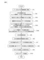
- FIG. 5 is a flow chart for explaining an example of control processing by the robot control device (control device) in the functional block diagram shown in FIG. 3.
- the conveyor control device 5 controls the conveyor 6 to move the workpiece 81 in the direction shown by the arrow 86 in FIG. 6 so that the workpiece 81 is included in the imaging range 35 of the visual sensor 30. Whether or not the workpiece 81 is included in the imaging range 35 can be recognized based on the output of the position detector 25.
- step ST2 the process proceeds to step ST2, where the three-dimensional information generating unit 61 generates three-dimensional information based on the output of the visual sensor 30 (e.g., a stereo image).
- the position detector 25 detects the first rotational position of the conveyor drive motor 24 and outputs it to the conveyor control device 5.
- step ST3 the two-dimensional image acquiring unit 62 acquires a two-dimensional image based on the output of the visual sensor 30 (e.g., a two-dimensional image from the first camera 31).
- the position detector 25 detects the second rotational position of the conveyor drive motor 24 and outputs it to the conveyor control device 5.
- a sensor e.g., a photoelectric sensor
- the rotational position (first and second rotational positions) of the position detector 25 may be detected based on the output of the sensor.
- the first rotational position and second rotational position output from the position detector 25 may be stored and held in the memory unit 52, for example.
- step ST4 the movement distance of the workpiece 81 on the conveyor 6 is calculated, and the process proceeds to step ST5.
- step ST5 the movement control unit 63 corrects the relative position of the three-dimensional information with respect to the two-dimensional image, and the process proceeds to step ST6.
- step ST6 the two-dimensional image processing range limiting unit 64 calculates (limits) the processing range from the two-dimensional image acquired by the two-dimensional image acquisition unit 62, and the process proceeds to step ST7.
- the processing range limiting process by the two-dimensional image processing range limiting unit 64 will be described in detail later with reference to Figures 6 to 9.
- the characteristic part detection unit 65 detects the characteristic part of the workpiece 81 in the two-dimensional image whose processing range has been limited by the two-dimensional image processing range limiting unit 64.
- a reference image of the top surface of the workpiece 81 is stored in advance in the storage unit 42.
- the reference image may be an image of the top surface of the workpiece 81 actually captured by a two-dimensional camera, or the reference image of the workpiece 81 may be generated based on three-dimensional data obtained by a CAD (Computer Aided Design) device.
- the characteristic part detection unit 65 detects an image of the top surface of the workpiece 81 in the two-dimensional image whose processing range has been limited by the two-dimensional image processing range limiting unit 64 by a method such as template matching using the reference image.
- the control device (robot system) of this embodiment even if the surface of the conveyor 6 (belt 6a) is mesh-like or the like, processing is performed based on a two-dimensional image whose processing range is limited by the two-dimensional image processing range limiting unit 64, so that it is possible to reduce erroneous detection of the workpiece 81, for example. Furthermore, the processing range of the two-dimensional image limited by the two-dimensional image processing range limiting unit 64 has a narrower processing region (area) than the two-dimensional image acquired by the two-dimensional image acquisition unit 62, making it possible to speed up processing.
- step ST8 the calculation unit 66 calculates the position and orientation of the workpiece 81.
- the position of the workpiece 81 can be set to, for example, the center of gravity of the rectangle on the top surface of the workpiece 81, a specific position, or the position of an end, and the orientation of the workpiece can be set to, for example, the normal direction of the top surface of the workpiece 81.
- the calculation unit 66 extracts measurement points located in an area overlapping the image 72a, and calculates the position and orientation of the workpiece 81 based on the coordinate values of the multiple measurement points.
- step ST9 the calculation unit 66 calculates the position and orientation of the robot 1 based on the position and orientation of the workpiece 81. That is, the calculation unit 66 calculates the position and orientation of the workpiece 81 when the workpiece 81 is moved by the conveyor 6 to a position where it is grasped by the hand 2, and calculates the position and orientation of the robot 1 based on the position and orientation of the workpiece 81 at that time.
- step ST10 the calculation unit 66 sends a command to the operation control unit 43 to drive the robot 1 and the hand 2.
- the operation control unit 43 drives the robot 1 and the hand 2 based on the command from the calculation unit 66, and the robot 1 (hand 2) grasps and transports the workpiece 81, and an example of the control process by the robot control device of this first embodiment ends (END).
- the two-dimensional image processing range limiting unit 64 limits the processing range from the two-dimensional image acquired by the two-dimensional image acquiring unit 62, and thus performs detection processing etc. based on the two-dimensional image that is actually required, thereby reducing erroneous detection etc. of the workpiece 81. Furthermore, since the processing range of the two-dimensional image limited by the two-dimensional image processing range limiting unit 64 has a smaller area than the two-dimensional image acquired by the two-dimensional image acquiring unit 62, processing can be speeded up.
- FIG. 6 is a diagram for explaining how three-dimensional information (three-dimensional point cloud data) of a workpiece is generated
- FIG. 7 is a diagram for explaining an example of processing by the two-dimensional image processing range limiting unit in the functional block diagram shown in FIG. 3.
- reference numeral 71 indicates a two-dimensional image (measurement area) acquired by the two-dimensional image acquisition unit 62
- 71a indicates the image area of the workpiece 81
- 71b indicates the image areas (measurement points PX) of both ends of the belt 6a of the conveyor 6
- 71c indicates the image area of the transport portion of the belt 6a
- 71d indicates the image area of the floor surface on which the conveyor 6 is installed.
- reference numeral 91 indicates the processing range limited (calculated) by the two-dimensional image processing range limiting unit 64, and 91a to 91c indicate margins.
- margin 91c is the portion before workpiece 81 arrives, it is considered preferable to set it wider than margin 91a, which is the portion after workpiece 81 arrives. Also, because margin 91b hardly deviates in the direction perpendicular to the movement direction of workpiece 81, it is considered acceptable to set it narrower than margin 91a, which is the portion after workpiece 81 arrives.
- the processing range limiting process by two-dimensional image processing range limiting unit 64 is not limited to the above.
- FIG. 8 is a diagram for explaining an example of processing by the two-dimensional image acquisition unit in the functional block diagram shown in FIG. 3.
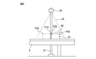
- the position of the workpiece 81 used to generate the three-dimensional information is indicated by a dashed line.
- the workpiece 81 moves in the direction indicated by the arrow 86 by the conveyor 6, and for example, the first camera 31 of the visual sensor 30 captures a two-dimensional image of the workpiece 81 when the workpiece 81 is transported inside the imaging range 35. That is, the visual sensor 30 can capture a two-dimensional image immediately after capturing an image for generating the three-dimensional information. Alternatively, the visual sensor 30 can capture a two-dimensional image a predetermined time after capturing an image for acquiring the three-dimensional information.
- the movement control unit 63 performs movement control for each measurement point, and the three-dimensional information includes, for example, the coordinate value of measurement point P1A placed on the surface of the workpiece 81.
- the movement control unit 63 processes measurement point P1A in the direction in which the workpiece 81 moves based on the amount of movement of the workpiece 81, and processes measurement points P1A and P2A to move to measurement points P1B and P2B.
- the movement control unit 63 changes the relative position of the three-dimensional information generated by the three-dimensional information generation unit 61 based on the processing range of the two-dimensional image limited by the two-dimensional image processing range limiting unit 64, for example, in a predetermined coordinate system (for example, the sensor coordinate system 78 shown in FIG. 1).
- FIG. 9 is a diagram for explaining another example of processing by the two-dimensional image processing range limiting unit in the functional block diagram shown in FIG. 3.
- the processing range limiting process by the two-dimensional image processing range limiting unit 64 described with reference to FIG. 7 limits the processing range 91 with margins 91a to 91c provided around the image area 71a of the workpiece 81, but the processing range limiting process by the two-dimensional image processing range limiting unit 64 described with reference to FIG. 9 limits the processing range to match the image area of the workpiece 81 in the two-dimensional image acquired by the two-dimensional image acquisition unit 62.
- FIG. 9 is a diagram for explaining another example of processing by the two-dimensional image processing range limiting unit in the functional block diagram shown in FIG. 3.
- the processing range limiting process by the two-dimensional image processing range limiting unit 64 described with reference to FIG. 7 limits the processing range 91 with margins 91a to 91c provided around the image area 71a of the workpiece 81, but the processing range limiting process by the
- reference symbol MK indicates a label such as a two-dimensional code attached to the top surface of the workpiece 81, for example, a cardboard box, and 79 indicates the image coordinate system.
- Reference symbols 72, 72a, 72b, and 72c indicate parts corresponding to 71, 71a, 71b, and 71c in FIG. 7 described above, and 87 indicates the direction in which the workpiece 81 moves.
- the two-dimensional image processing range limiting unit 64 limits the image area 72a (71a) of the workpiece 81 in the two-dimensional image 72 acquired by the two-dimensional image acquisition unit 62 as the processing range for actually performing processing. That is, for example, when reading a label MK affixed to the top surface of a workpiece 81, it is conceivable that the label MK can be read even if the processing range limited by the two-dimensional image processing range limiting unit 64 is the image area of the workpiece 81.
- three-dimensional information (three-dimensional position information) at the timing when the two-dimensional image acquisition unit 62 acquires the two-dimensional image (when the visual sensor 30 captures the two-dimensional image) can be obtained.
- the distance [mm] from the visual sensor 30 to the top surface of the cardboard box (workpiece 81) can be obtained, and the obtained X, Y position information [mm] of the cardboard box can be converted into position information [pixel] on the two-dimensional image.
- the four corners (x1, y1), (x2, y1), (x1, y2), (x2, y2) of the cardboard box (workpiece 81) are converted into the four corners (h1, w1), (h2, w1), (h1, w2), (h2, w2) on the two-dimensional image acquired by the two-dimensional image acquisition unit 62, and the four corners on this two-dimensional image can be set as the processing range limited by the two-dimensional image processing range limiting unit 64 to detect the label MK.
- control device control method
- this embodiment is not limited to application to a robot system that grasps a moving workpiece and performs work, or a robot system that detects a label affixed to the top surface of a moving workpiece and performs work, but can be widely applied to robot systems that perform various processes on a moving workpiece.
- FIG. 10 is a flow chart for explaining another example of the control process by the robot control device (control device) in the functional block diagram shown in FIG. 3.
- the control process shown in FIG. 10 corresponds to the control process described with reference to FIG. 5, with the processes of steps ST3 and ST4 replaced with ST31 to ST34.
- the conveyor control device 5 controls the conveyor 6 to move the workpiece 81 in the direction shown by the arrow 86 in FIG. 6, and the process proceeds to step ST2.
- step ST2 the three-dimensional information generating unit 61 generates three-dimensional information based on the output of the visual sensor 30, and the position detector 25 detects the first rotational position of the conveyor drive motor 24 and outputs it to the conveyor control device 5, and then the process proceeds to step ST31.
- step ST31 the specified height (Z: vertical direction relative to the XY plane of the two-dimensional image) range is read from memory (storage unit 42), and the process proceeds to step ST32, where the contour (current position) of the workpiece 81 is detected from three-dimensional points (three-dimensional point cloud data) within the range (imaging range 35 in FIG. 8).
- the contour of the workpiece 81 in the XY plane can be defined, for example, as a circumscribed rectangle including points (x, y) obtained by projecting the three-dimensional points onto the XY plane.
- the three-dimensional points read from memory and processed can be, for example, data of a predetermined range in the height (Z) direction relative to the surface of the belt 6a of the conveyor 6.
- This height range can be set appropriately in advance, for example, depending on the type and shape of the workpiece 81 handled by the robot system 100. Specifically, if the shape of the workpiece 81 handled by the robot system 100 is known in advance, for example, the tallest workpiece 81max and the shortest workpiece 81min among the workpieces 81 handled can be positioned within the imaging range 35 and detected, making it possible to set the height range without directly specifying a numerical value.
- step ST33 calculate the second rotation position of the conveyor drive motor 24 when the center of the outline of the workpiece 81 becomes the center of the field of view of the two-dimensional image in relation to the moving direction of the conveyor 6, and proceed to step ST34.
- step ST34 obtain a two-dimensional image at the timing when the rotation position of the conveyor drive motor 24 reaches the second rotation position, proceed to step ST5, and correct the three-dimensional information. Note that the processing of the subsequent steps ST6 to ST10 is the same as that described with reference to FIG. 5, and the description thereof will be omitted.
- the two-dimensional image processing range limiting unit 64 can limit the processing range in the two-dimensional image obtained by the two-dimensional image obtaining unit 62, for example, based on the current position of the workpiece 81 in the three-dimensional information generated by the three-dimensional information generating unit 61.
- the control processing by the robot control device is not limited to the above example, and it goes without saying that various changes and modifications are possible.
- FIG. 11 is a plan view showing a schematic overall configuration of a second embodiment of the robot system according to this embodiment.
- a transport vehicle 7 is used in place of the conveyor 6 in the robot system 100 of the first embodiment. That is, in the robot system 200 of the second embodiment, the transport vehicle 7 is an example of a moving device that transports a workpiece 81, and the workpiece 81 is placed on a mounting table 7a and automatically moves, for example, along a tape 39 affixed to the floor surface. That is, the transport vehicle 7 includes a sensor that detects the tape 39, and automatically moves along the tape 39 while detecting the tape 39 with the sensor.
- a visual sensor 30 fixed to a support member 37 is disposed above the path along which the transport vehicle 7 moves.
- This visual sensor 30 is similar to that in the robot system 100 of the first embodiment described above, and is disposed in a position where it can capture an image of the workpiece 81 being moved by the transport vehicle 7.
- the transport vehicle 7 includes a drive motor for driving the wheels, and a position detector equivalent to the position detector 25 attached to the conveyor drive motor 24 of the conveyor 6 is attached to the output shaft of the drive motor.
- the position of the mounting platform 7a can be determined, for example, by the position of a set point set at an arbitrary position on the transport vehicle 7, and for example, the control device 4 shown in FIG. 3 can recognize the position of the mounting platform 7a (workpiece 81).
- the conveyor 6 and the transport vehicle 7 can be used as the moving device for transporting the workpiece 81, but are not limited to these, and for example, a robot for transporting the workpiece 81 can also be used.
- the imaging device 3 visual sensor 30
- various devices can be used as long as they can acquire and synchronize two-dimensional images and three-dimensional information (three-dimensional point cloud data) by moving the three-dimensional information in a predetermined coordinate system. In this way, according to this embodiment, it is possible to provide a control device, robot system, and control method that are highly accurate and capable of high-speed processing.
- a control device (4) that receives an output from a visual sensor (30) that captures an image of a moving work (81) and controls processing of the work (81), A two-dimensional image acquisition unit (62) that acquires a two-dimensional image including the work (81) based on an output of the visual sensor (30); A three-dimensional information generating unit (61) that generates three-dimensional information including the work (81) based on an output of the visual sensor (30); a two-dimensional image processing range limiting unit (64) that limits a processing range in the acquired two-dimensional image; and a movement control unit (63) for changing a relative position of the three-dimensional information based on a limited processing range of the two-dimensional image in a predetermined coordinate system.
- the two-dimensional image processing range limiting unit (64) limits a processing range in the acquired two-dimensional image based on a current position of the workpiece (81) in the generated three-dimensional information. 2.
- the two-dimensional image processing range limiting unit (64) limits a processing range by adding a margin to an image area of the work (81) in the acquired two-dimensional image.
- the two-dimensional image processing range limiting unit (64) limits the processing range in the acquired two-dimensional image so that a front margin in a direction in which the workpiece (81) moves is wider than a rear margin in a direction in which the workpiece (81) moves. 4.
- the two-dimensional image processing range limiting unit (64) limits the processing range in the acquired two-dimensional image so that the margins on both sides of the direction in which the workpiece (81) moves are narrower than the rear margin of the direction in which the workpiece (81) moves. 5.
- the two-dimensional image processing range limiting unit (64) limits a processing range in the acquired two-dimensional image so as to coincide with an image area of the work (81). 3.
- an operation control unit is provided that controls processing of the work (81) based on the limited processing range of the two-dimensional image and the three-dimensional information. 7. The control device according to claim 1 .
- the movement control unit calculates a movement amount of the work (81) based on a first position of the work (81) when the output of the visual sensor (30) is used to generate the three-dimensional information and a second position of the work (81) when the output of the visual sensor (30) is used to acquire the two-dimensional image, and moves the three-dimensional information so as to correspond to the movement amount of the work (81) in the coordinate system, thereby moving the three-dimensional information within a limited processing range of the two-dimensional image.
- the control device according to claim 1 .
- the moving device is a conveyor (6) or a transport vehicle (7) that carries and moves the work (81). 10.
- the visual sensor (30) is a sensor capable of acquiring two-dimensional images and three-dimensional information. 11. The robot system according to claim 9 or 10.
- Robot 2 Hand 3 Imaging device 4 Robot control device (control device) 5 Conveyor control device 6 Conveyor (moving device) 7 Transport vehicle (mobile device) Description of the Reference Signs 23, 25 Position detector 24 Conveyor drive motor 26 Conveyor drive device 30 Visual sensor 31 First camera 32 Second camera 33 Projector 41 Operation program 42, 52 Memory unit 43, 53 Operation control unit 44 Hand drive unit 45 Robot drive unit 46 Display 47 Image processing unit 54 Conveyor drive unit 61 Three-dimensional information generation unit 62 Two-dimensional image acquisition unit 63 Movement control unit 64 Two-dimensional image processing range limiting unit 65 Characteristic portion detection unit 66 Calculation unit 71 Measurement area 81 Workpiece 91 Processing range 91a, 91b, 91c Margin 100, 200 Robot system
Landscapes
- Engineering & Computer Science (AREA)
- Physics & Mathematics (AREA)
- General Physics & Mathematics (AREA)
- Theoretical Computer Science (AREA)
- Multimedia (AREA)
- Computer Vision & Pattern Recognition (AREA)
- Manipulator (AREA)
Abstract
精度が高く高速処理が可能な制御装置の提供を図る。制御装置は、移動するワークを撮像する視覚センサの出力を受け取って、ワークに対する処理を制御し、2次元画像取得部と、3次元情報生成部と、2次元画像処理範囲限定部と、移動制御部と、を備える。2次元画像取得部は、視覚センサの出力に基づいて、ワークを含む2次元画像を取得し、3次元情報生成部は、視覚センサの出力に基づいて、ワークを含む3次元情報を生成する。2次元画像処理範囲限定部は、取得された2次元画像における処理範囲を限定し、移動制御部は、予め定められた座標系において、限定された2次元画像の処理範囲に基づいて3次元情報の相対位置を変更する。
Description
本開示は、制御装置、ロボットシステムおよび制御方法に関する。
従来、視覚センサ(撮像装置)により撮像した画像に基づいて、ワーク(対象物)の表面形状およびワークの位置等を検出し、ワークに対する所定の作業をロボットに行わせる制御装置(ロボット制御装置)が提供されている。ここで、視覚センサとしては、ワークの2次元画像を撮像する2次元センサ、或いは、視覚センサからワークまでの距離等の3次元情報を測定する3次元センサが使用されている。
また、従来、上述した制御装置により、作業ツール(エンドエフェクタ)を備えたロボットを制御し、移動するワークに対して所定の作業を行うロボットシステムも実用化されている。このようなロボットシステムにおいて、制御装置は、視覚センサの出力から取得した2次元画像および3次元情報に基づいてワークの位置および姿勢を算出し、例えば、ロボットのハンド(作業ツール)を制御してワークを把持するといった作業を制御する。なお、ワークの移動(搬送)は、例えば、コンベヤおよび搬送車等により行われる。
ところで、従来、視覚センサの出力から取得した2次元画像と3次元情報に基づいてワークに対する所定の作業を制御する制御技術としては、様々な提案がなされている。
前述したように、従来、例えば、2次元センサの出力から取得した2次元画像および3次元センサの出力から生成した3次元情報を使用し、ロボットを制御して移動するワークに対する所定の作業を行うロボットシステムが実用化されている。
しかしながら、このような従来のロボットシステムでは、例えば、ワークを搬送するコンベヤの表面が網目状等になっていると2次元画像におけるワークや特徴個所の検出精度の低下を来たす虞がある。さらに、ワークを含む2次元画像と3次元情報に基づいて検出処理を行う場合、視覚センサの高解像度化等に伴って処理するデータ量が大きくなり、高性能の演算処理装置が必要になり、或いは、検出処理を高速に行うことが難しくなるといった問題もある。
そこで、精度が高く高速処理が可能な制御装置、ロボットシステムおよび制御方法の提供が要望されている。
本開示に係る一実施形態によれば、移動するワークを撮像する視覚センサの出力を受け取って、ワークに対する処理を制御する制御装置であって、2次元画像取得部と、3次元情報生成部と、2次元画像処理範囲限定部と、移動制御部とを備える制御装置が提供される。
2次元画像取得部は、視覚センサの出力に基づいて、ワークを含む2次元画像を取得し、3次元情報生成部は、視覚センサの出力に基づいて、ワークを含む3次元情報を生成する。2次元画像処理範囲限定部は、取得された2次元画像における処理範囲を限定し、移動制御部は、予め定められた座標系において、限定された2次元画像の処理範囲に基づいて3次元情報の相対位置を変更する。
以下、本実施形態に係る制御装置、ロボットシステムおよび制御方法の実施例を、添付図面を参照して詳述する。各図面において、同一または類似の構成要素には同一または類似の符号が付与されている。また、以下に記載する実施形態は、特許請求の範囲に記載される発明の技術的範囲および用語の意義を限定するものではない。
図1は、本実施形態に係るロボットシステムの第1実施例の全体構成を概略的に示す正面図であり、図2は、図1に示すロボットシステムの平面図である。図1および図2において、参照符号100は、第1実施例のロボットシステムを示し、1はロボット、2はハンド、3は撮像装置、6はコンベヤ、そして、81はワーク(対象物)を示す。図1および図2に示されるように、ロボットシステム100は、ハンド2を備えたロボット1,コンベヤ6および撮像装置3を備える。
ロボット1は、設置面に固定されたベース部14,ベース部14に対して回転する旋回ベース13,旋回ベース13に回動可能に支持された下部アーム12,下部アーム12に回動可能に支持された上部アーム11,上部アーム11の端部に回動可能に支持されたリスト15を含む。ここで、上部アーム11は、上部アーム11の延びる方向に平行な回転軸の周りに回転し、また、リスト15の先端には、回転可能に形成されているフランジ16が設けられている。なお、本実施形態の説明において、ロボット1は、複数の関節部を有する多関節ロボットとされているが、この形態に限定されず、様々な作業ツールを制御することができる任意のロボットを適用することができる。また、ワーク81は、一例として直方体形状の段ボール箱として描いているが、ワーク81は段ボール箱に限定されないのはもちろんである。
ハンド2は、ワーク81を把持することが可能な作業ツールであり、例えば、複数の吸着パッド2aによりワーク81を吸着して把持するようになっている。ハンド2は、リスト15のフランジ16に固定されているが、ロボット1に取り付けられる作業ツールとしては、任意の作業ツールを適用することができる。
コンベヤ6は、ワーク81を搬送する移動装置の一例であり、環状のベルト6aを回転することによりワーク81を予め定められた方向に搬送する。すなわち、コンベヤ6は、矢印86に示されるように、ワーク81を水平方向に移動し、ロボット1が位置および姿勢を変更してハンド2がワーク81を把持することができる位置までワーク81を搬送するようになっている。
撮像装置3は、ワーク81の2次元画像を撮像する2次元センサ(視覚センサ30)、および、ワーク81の表面の3次元情報を取得するための3次元センサ(視覚センサ30)を含む。すなわち、視覚センサ30の出力に基づいて、コンベヤ6で搬送されるワーク81の2次元画像を撮像すると共に、ワーク81の表面の3次元情報(3次元点群データ、3次元位置情報)を取得することができる。ここで、参照符号24は、コンベヤ6の環状ベルト6aを駆動するコンベヤ駆動モータを示し、25は、例えば、エンコーダ等の位置検出器を示す。なお、視覚センサ30の一例は、図4を参照して後に詳述する。
視覚センサ30は、支持部材37により支持され、コンベヤ6により搬送されるワーク81を撮像できる位置に配置されている。なお、視覚センサ30は、ワーク81が搬送される方向においてロボット1よりも上流側に配置されている。ここで、ロボットシステム100には、基準座標系としてのワールド座標系76が設定され、例えば、ロボット1のベース部14にワールド座標系76の原点が配置されている。これにより、ロボット1の位置および姿勢が変化してもワールド座標系76の位置および向きは変化しないようになっている。なお、ワールド座標系76は、座標軸として、互いに直交するX軸、Y軸およびZ軸を有し、X軸、Y軸およびZ軸の周りの座標軸としてW軸、P軸およびR軸が設定されている。
さらに、ロボットシステム100では、作業ツールの任意の位置に設定された原点を有するツール座標系77が設定され、ツール座標系77の原点は、ハンド2の工具先端点に設定されている。これにより、ロボット1が位置および姿勢を変化すると、ツール座標系77の位置および姿勢が変化し、例えば、ロボット1の位置は、工具先端点の位置に相当し、ロボット1の姿勢は、ワールド座標系76に対するツール座標系77の向きに相当する。また、ロボットシステム100では、視覚センサ30に対応してセンサ座標系78が設定され、センサ座標系78の原点が視覚センサ30に固定された座標系となっている。これにより、ワールド座標系76に対するセンサ座標系78の位置および姿勢に基づいて、センサ座標系78における座標値をワールド座標系76における座標値に変換することができる。
図3は、図1に示すロボットシステムの機能ブロック図であり、ロボットシステム100は、さらに、ロボット制御装置(制御装置)4およびコンベヤ制御装置5を備える。図1~図3に示されるように、ロボット1は、ロボット1の位置および姿勢を変化させる複数のロボット駆動モータ22および各ロボット駆動モータ22に取り付けられたエンコーダ等の位置検出器23を含む。ハンド2は、例えば、吸着パッド2aの内部を減圧してワーク81を吸着するためのポンプ21を含む。
ロボット制御装置4は、記憶部42,動作制御部43,ハンド駆動部44,ロボット駆動部45,表示器46および画像処理部47を含む。ここで、動作制御部43および画像処理部47は、演算処理装置として機能するマイクロプロセッサ(MPU)により構成され、RAM(Random Access Memory)、ROM(Read Only Memory)およびフラッシュメモリ等の記憶部42との間でデータを授受して様々な処理を行う。なお、ロボット1,ハンド2およびコンベヤ6等の制御を行う動作プログラム41は、記憶部42に格納され、演算処理装置(動作制御部43および画像処理部47等)により実行される。
動作制御部43は、動作プログラム41に従った動作指令をハンド駆動部44およびロボット駆動部45に出力し、ハンド2およびロボット1を制御する。また、動作制御部43は、動作プログラム41に従った動作指令を画像処理部47に出力し、視覚センサ30の出力に基づいた2次元画像の取得、3次元情報の生成および画像処理等を制御する。なお、表示器46は、例えば、液晶表示パネル等で構成され、ハンド2,ロボット1およびコンベヤ6の制御に関する情報等を表示する。
コンベヤ制御装置5は、記憶部52,動作制御部53およびコンベヤ駆動部54を含み、ロボット制御装置4からの指令に基づいてコンベヤ6を制御し、ワーク81を所定位置まで搬送するようになっている。ここで、コンベヤ6は、コンベヤ駆動モータ24および位置検出器25を含んで構成されている。なお、位置検出器25は、例えば、コンベヤ駆動モータ24の出力シャフトに取り付けられたエンコーダ(ロータリエンコーダ)として構成することができ、このエンコーダの出力に基づいて、コンベヤ6により搬送されるワーク81の概略的な位置を認識することができる。なお、位置検出器25は、エンコーダに限定されず、例えば、光電センサ等を適用することもできる。
画像処理部47は、3次元情報生成部61,2次元画像取得部62,移動制御部63,2次元画像処理範囲限定部64,特徴部位検出部65および算出部66を含む。3次元情報生成部61は、3次元センサの出力に基づいて3次元情報を生成し、2次元画像取得部62は、2次元センサの出力に基づいて2次元画像を取得する。移動制御部63は、2次元画像に対する3次元情報の相対位置を修正し、2次元画像処理範囲限定部64は、2次元画像取得部62が取得した2次元画像から、より狭い範囲の2次元画像を限定し、その限定された2次元画像を処理範囲として出力する。
特徴部位検出部65は、ワーク81の予め定められた特徴部位を検出し、算出部66は、ワーク81の位置および姿勢に基づいてロボット1の位置および姿勢を算出する。ここで、画像処理部47は、ロボット制御装置4に内蔵せず、ロボット制御装置4の外部に別体として設けてもよく、また、コンベヤ制御装置5は、ロボット制御装置4に内蔵することもでき、様々な変更および変形が可能である。
図4は、図3に示す機能ブロック図における視覚センサの一例を説明するための図である。図4に示されるように、視覚センサ30(撮像装置3)は、第1カメラ31,第2カメラ32およびプロジェクタ33を含む。ここで、第1カメラ31および第2カメラ32は、ステレオカメラとして機能するが、それぞれのカメラ31または32は、2次元画像を撮像する2次元カメラとしても機能する。なお、カメラ31,32としては、CCD(Charge-Coupled Device)センサまたはCMOS(Complementary Metal-Oxide Semiconductor)センサ等の撮像素子を備えた任意のカメラを適用することができる。また、2台のカメラ31,32は、予め定められ位置に離れて配置されている。
プロジェクタ33は、例えば、ワーク81に対して縞模様等のパターン光を投影するもので、筐体34の内部にカメラ31,32およびプロジェクタ33が配置されている。ここで、3次元情報生成部61が視覚センサ30の出力に基づいて3次元情報を生成する場合、例えば、プロジェクタ33はパターン光を投影し、第1カメラ31および第2カメラ32によるステレオ画像(2つの2次元画像)を使用する。また、2次元画像取得部62が視覚センサ30の出力に基づいて2次元画像を取得する場合、例えば、プロジェクタ33からのパターン光を停止し、第1カメラ31または第2カメラ32の一方により撮像された2次元画像を使用する。従って、3次元情報生成部61が視覚センサ30の出力を処理するタイミングは、2次元画像取得部62が視覚センサ30の出力を取得するタイミングと異なるのが好ましい。ただし、視覚センサ30が、例えば、TOF(Time Of Flight)方式のような3次元情報生成部61に出力するための専用の3次元センサ、および、2次元画像取得部62に出力するための専用の2次元センサの両方を備えている場合には、タイミングの差異を設けることなく処理することも可能である。さらに、視覚センサ30としては、上述した例の他に知られている様々な3次元センサおよび2次元センサを適用することができるのは言うまでもない。
図3および図4に示されるように、3次元情報生成部61は、視覚センサ30により取得された画像を処理することにより、撮像対象の表面の3次元情報を3次元点群データ(3次元マップ)として生成することができる。ここで、3次元情報には、例えば、撮像対象の表面に設定された複数の測定点の位置に関する情報が含まれる。また、3次元点群データは、撮像対象の表面に設定された測定点の座標値(x,y,z)の集合により撮像対象の表面の位置を表現したものである。
3次元情報生成部61は、例えば、視覚センサ30の撮像範囲35の内部の撮像対象における表面の複数の測定点を設定するが、これらの測定点は、カメラ31またはカメラ32の2次元画像の画素ごとに設定することができる。また、3次元情報生成部61は、2台のカメラ31,32により撮像される2次元画像の視差に基づいて、視覚センサ30から各測定点までの距離を算出することができる。そして、3次元情報生成部61は、視覚センサ30から各測定点までの距離に基づいて、センサ座標系78における測定点の座標値を算出する。或いは、視覚センサ30の位置および姿勢に基づいて、センサ座標系78の座標値をワールド座標系76の座標値に変換することもできる。このようにして、3次元情報生成部61は、複数の測定点の座標値を含む3次元点群データ(3次元情報)を生成する。
移動制御部63は、コンベヤ6の位置検出器25の出力を取得し、3次元情報を生成するためにステレオ画像を撮像したタイミングから2次元画像を撮像したタイミングまでに移動したワーク81の実際の移動量を算出する。そして、移動制御部63は、ワーク81の移動量に対応するように、予め定められた座標系において、2次元画像に対応するように3次元情報を移動する制御を行う。この制御により、上記の座標系においてワーク81の3次元情報の少なくも一部とワーク81の2次元画像とを重ねることができる。換言すれば、同一の時刻に取得した3次元情報および2次元画像と同等の3次元情報および2次元画像を生成することができる。
図5は、図3に示す機能ブロック図におけるロボット制御装置(制御装置)による制御処理の一例を説明するためのフローチャートである。図5に示されるように、本第1実施例のロボット制御装置による制御処理の一例が開始(START)すると、ステップST1において、コンベヤ制御装置5はコンベヤ6を制御して、ワーク81を図6中の矢印86に示す方向へ移動し、ワーク81を視覚センサ30の撮像範囲35に含まれるようにする。なお、ワーク81が撮像範囲35に含まれたか否かは、位置検出器25の出力に基づいて認識することができる。
次に、ステップST2に進み、3次元情報生成部61は、視覚センサ30の出力(例えば、ステレオ画像)に基づいて、3次元情報を生成する。このとき、位置検出器25は、コンベヤ駆動モータ24の第1の回転位置を検出してコンベヤ制御装置5に出力する。さらに、ステップST3に進んで、2次元画像取得部62は、視覚センサ30の出力(例えば、第1カメラ31による2次元画像)に基づいて、2次元画像を取得する。このとき、位置検出器25は、コンベヤ駆動モータ24の第2の回転位置を検出してコンベヤ制御装置5に出力する。
ここで、コンベヤ6に対して、ワーク81が撮像範囲35に到来したことを検出するセンサ(例えば、光電センサ)を設け、そのセンサの出力に基づいて位置検出器25の回転位置(第1および第2の回転位置)を検出するように構成してもよい。なお、位置検出器25から出力された第1の回転位置および第2の回転位置は、例えば、記憶部52に格納して保持される。
そして、ステップST4に進んで、コンベヤ6におけるワーク81の移動距離を算出し、ステップST5に進む。ステップST5において、移動制御部63は、2次元画像に対する3次元情報の相対位置を修正し、ステップST6に進む。ステップST6において、2次元画像処理範囲限定部64は、2次元画像取得部62により取得された2次元画像から処理範囲を算出(限定)し、ステップST7に進む。ここで、2次元画像処理範囲限定部64による処理範囲の限定処理に関しては、後に、図6~図9を参照して詳述する。
ステップST7において、特徴部位検出部65は、2次元画像処理範囲限定部64により処理範囲が限定された2次元画像において、ワーク81の特徴部位を検出する。ここで、例えば、ワーク81の上面が特徴部位に設定されている場合には、ワーク81の上面の基準画像を予め記憶部42に記憶する。また、基準画像は、2次元カメラにより実際にワーク81の上面を撮像した画像を採用することができ、或いは、CAD(Computer Aided Design)装置により得られた3次元データに基づいてワーク81の基準画像を生成することもできる。特徴部位検出部65は、基準画像を用いたテンプレートマッチング等の手法により、2次元画像処理範囲限定部64により処理範囲が限定された2次元画像においてワーク81の上面の画像を検出する。
このように、本実施形態の制御装置(ロボットシステム)によれば、例えば、コンベヤ6(ベルト6a)の表面が網目状等になっていたとしても、2次元画像処理範囲限定部64により処理範囲が限定された2次元画像に基づいて処理を行うため、例えば、ワーク81の誤検出を低減することができる。さらに、2次元画像処理範囲限定部64により限定された2次元画像の処理範囲は、2次元画像取得部62により取得された2次元画像よりも処理領域(面積)が狭くなるため処理を高速化することが可能になる。
次に、ステップST8に進んで、算出部66が、ワーク81の位置および姿勢を算出する。ここで、ワーク81の位置としては、例えば、ワーク81の上面の長方形の重心位置、特定の位置、或いは、端部の位置等を設定することができ、ワークの姿勢としては、ワーク81の上面の法線方向等を設定することができる。算出部66は、画像72aに重なる領域に配置されている測定点を抽出し、複数の測定点の座標値に基づいて、ワーク81の位置および姿勢を算出する。
さらに、ステップST9に進んで、算出部66が、ワーク81の位置および姿勢に基づいて、ロボット1の位置および姿勢を算出する。すなわち、算出部66は、ワーク81がハンド2により把持される位置までコンベヤ6により移動したときのワーク81の位置および姿勢を算出し、その時のワーク81の位置および姿勢に基づいてロボット1の位置および姿勢を算出する。
そして、ステップST10に進んで、算出部66が、動作制御部43に対してロボット1およびハンド2を駆動する指令を送出する。動作制御部43は、算出部66からの指令に基づいて、ロボット1およびハンド2を駆動し、ロボット1(ハンド2)がワーク81を把持して搬送し、本第1実施例のロボット制御装置による制御処理の一例を終了(END)する。
このように、本第1実施例のロボット制御装置による制御処理の一例によれば、2次元画像処理範囲限定部64が、2次元画像取得部62により取得された2次元画像から処理範囲を限定することにより、実際に必要な2次元画像に基づいて検出処理等を行うため、ワーク81の誤検出等を低減することができる。さらに、2次元画像処理範囲限定部64により限定された2次元画像の処理範囲は、2次元画像取得部62により取得された2次元画像よりも面積が狭くなるため、処理を高速化することができる。
図6は、ワークの3次元情報(3次元点群データ)を生成する様子を説明するための図であり、図7は、図3に示す機能ブロック図における2次元画像処理範囲限定部による処理の一例を説明するための図である。まず、図6に示されるように、ワーク81は、コンベヤ6により、矢印86の向きへ搬送され、ワーク81を含む撮像範囲35が視覚センサ30により撮像される。図7において、参照符号71は、2次元画像取得部62により取得された2次元画像(測定領域)を示し、71aは、ワーク81の画像領域、71bは、コンベヤ6のベルト6aの両端の画像領域(測定点PX)、71cはベルト6aの搬送部分の画像領域、そして、71dは、コンベヤ6が設置される床面の画像領域を示す。さらに、参照符号91は、2次元画像処理範囲限定部64により限定(算出)された処理範囲を示し、91a~91cはマージンを示す。
図7に示されるように、2次元画像処理範囲限定部64は、2次元画像取得部62により取得された2次元画像71において、ワーク81の画像領域71aにマージン91a~91cを付加し、実際に処理を行うための処理範囲91として限定する。ここで、処理範囲91は、ワーク81が移動する向きの前方のマージン91cが、ワーク81が移動する向きの後方のマージン91aよりも広くなるように、さらに、ワーク81が移動する向きの両側のマージン91b,91bが、ワーク81が移動する向きの後方のマージン91aよりも狭くなるように規定されている。
すなわち、マージン91cは、ワーク81が到達する前の部分であるため、ワーク81が到達した後の部分であるマージン91aよりも広く設定するのが好ましいと考えられるからである。また、マージン91bは、ワーク81の移動方向に対して直角方向で殆どずれないため、ワーク81が到達した後の部分であるマージン91aよりも狭く設定しても問題ないと考えられるからである。なお、2次元画像処理範囲限定部64による処理範囲の限定処理は、上述したものに限定されるものではない。
図8は、図3に示す機能ブロック図における2次元画像取得部による処理の一例を説明するための図である。図8において、3次元情報を生成するのに使用したワーク81の位置が破線で示されている。ワーク81は、コンベヤ6により矢印86に示される向きに移動するが、例えば、視覚センサ30の第1カメラ31は、撮像範囲35の内部にワーク81が搬送されてきた時にワーク81の2次元画像を撮像する。すなわち、視覚センサ30は、3次元情報を生成するための撮像を行った直後に2次元画像を撮像することができる。或いは、視覚センサ30は、3次元情報を取得するための撮像を行った後の予め定められた時間の経過後に2次元画像を撮像することもできる。
図8に示されるように、移動制御部63は、それぞれの測定点ごとに移動制御を行うが、例えば、3次元情報には、ワーク81の表面に配置された測定点P1Aの座標値が含まれる。移動制御部63は、測定点P1Aをワーク81が移動する方向にワーク81の移動量に基づいて処理し、測定点P1A,P2Aが測定点P1B,P2Bに移動するように処理する。ここで、移動制御部63は、例えば、予め定められた座標系(例えば、図1に示すセンサ座標系78)において、2次元画像処理範囲限定部64により限定された2次元画像の処理範囲に基づいて、3次元情報生成部61により生成された3次元情報の相対位置を変更する。
図9は、図3に示す機能ブロック図における2次元画像処理範囲限定部による処理の他の例を説明するための図である。図7を参照して説明した2次元画像処理範囲限定部64による処理範囲の限定処理は、ワーク81の画像領域71aの周囲にマージン91a~91cを設けた処理範囲91を限定するものであるが、図9を参照して説明する2次元画像処理範囲限定部64による処理範囲の限定処理は、2次元画像取得部62により取得した2次元画像において、ワーク81の画像領域に一致するように処理範囲を限定するものである。図9において、参照符号MKは、例えば、段ボール箱のワーク81の上面に貼着された2次元コード等のラベルを示し、79は、画像座標系を示す。なお、参照符号72,72a,72b,72cは、前述した図7の71,71a,71b,71cに対応する部分を示し、87は、ワーク81の移動する向きを示す。
図9に示されるように、例えば、視覚センサ30によりワーク81の上面に貼着されたラベルMKを読み取って所定の作業を行う場合、2次元画像処理範囲限定部64は、2次元画像取得部62により取得された2次元画像72において、ワーク81の画像領域72a(71a)を、実際に処理を行うための処理範囲として限定する。すなわち、例えば、ワーク81の上面に貼着されたラベルMKを読み取る場合、2次元画像処理範囲限定部64により限定する処理範囲をワーク81の画像領域としても、ラベルMKを読み取ることが可能である考えられる。
具体的に、前述した図5に示すフローチャートのステップST5において3次元情報を修正することにより、例えば、2次元画像取得部62が2次元画像を取得した(視覚センサ30が2次元画像を撮像した)タイミングにおける3次元情報(3次元位置情報)が得られる。この3次元情報における高さ方向(Z軸)の情報により、視覚センサ30から段ボール箱(ワーク81)の上面までの距離[mm]を得ることができ、その得られた段ボール箱のX,Yの位置情報[mm]を2次元画像上の位置情報[pixel]に変換することができる。すなわち、段ボール箱(ワーク81)の四隅(x1, y1), (x2, y1), (x1, y2), (x2, y2)を、2次元画像取得部62が取得した2次元画像上の四隅(h1, w1), (h2, w1), (h1, w2), (h2, w2)に変換し、この2次元画像上の画像上の四隅を、ラベルMKを検出するために2次元画像処理範囲限定部64により限定する処理範囲として設定することができる。なお、本実施形態に係る制御装置(制御方法)は、移動するワークを把持して作業を行うロボットシステム、或いは、移動するワークの上面に貼着されたラベルを検出して作業を行うロボットシステムに適用されるのに限定されず、移動するワークに対して様々な処理を行うロボットシステムに対して幅広く適用することができる。
図10は、図3に示す機能ブロック図におけるロボット制御装置(制御装置)による制御処理の他の例を説明するためのフローチャートである。ここで、図10に示す制御処理は、図5を参照して説明した制御処理において、ステップST3およびST4の処理をST31~ST34に置き換えたものに相当する。図10に示されるように、本第1実施例のロボット制御装置による制御処理の他の例が開始(START)すると、ステップST1において、コンベヤ制御装置5はコンベヤ6を制御して、ワーク81を図6中の矢印86に示す方向へ移動し、ステップST2に進む。ステップST2において、3次元情報生成部61が視覚センサ30の出力に基づいて3次元情報を生成し、位置検出器25がコンベヤ駆動モータ24の第1の回転位置を検出してコンベヤ制御装置5に出力した後、ステップST31に進む。
ステップST31では、指定された高さ(Z:2次元画像のXY平面に対する垂直方向)の範囲をメモリ(記憶部42)から読み込み、さらに、ステップST32に進んで、範囲(図8における撮像範囲35)内の3次元点(3次元点群データ)よりワーク81の外形(現在位置)を検出する。ここで、XY平面におけるワーク81の外形は、例えば、3次元点をXY平面に射影した点(x,y)を含む外接長方形として規定することができる。また、メモリから読み込んで処理する3次元点としては、例えば、コンベヤ6のベルト6aの表面に対して、高さ(Z)方向の所定範囲のデータとすることができる。この高さ方向の範囲は、例えば、予めロボットシステム100が扱うワーク81の種類や形状等に応じて適宜設定することができる。具体的に、ロボットシステム100が扱うワーク81の形状が予め分かっている場合、例えば、その扱うワーク81における最も高さが高いワーク81maxと最も高さが低いワーク81minを撮像範囲35内に配置して検出させることで、高さの範囲を数値で直接指定することなく設定することが可能になる。
次に、ステップST33に進んで、コンベヤ6の移動方向に関してワーク81の外形中心が2次元画像の視野中心になるときのコンベヤ駆動モータ24の第2の回転位置を算出し、ステップST34に進む。ステップST34では、コンベヤ駆動モータ24の回転位置が第2の回転位置にきたタイミングで2次元画像を取得し、ステップST5に進み、3次元情報を修正する。なお、以降のステップST6~ST10の処理は、図5を参照して説明したのと同様であり、その説明は省略する。このように、2次元画像処理範囲限定部64は、例えば、3次元情報生成部61により生成された3次元情報におけるワーク81の現在位置に基づいて、2次元画像取得部62取得されたにより2次元画像における処理範囲を限定することができる。なお、ロボット制御装置による制御処理としては、上述した例に限定されず、様々な変更および変形が可能なのは言うまでもない。
図11は、本実施形態に係るロボットシステムの第2実施例の全体構成を概略的に示す平面図である。図11と前述した図2との比較から明らかなように、本第2実施例のロボットシステム200では、第1実施例のロボットシステム100におけるコンベヤ6の代わりとして搬送車7を適用している。すなわち、第2実施例のロボットシステム200において、搬送車7は、ワーク81を搬送する移動装置の一例であり、ワーク81を載置台7aの上に載置し、例えば、床面に貼り付けられたテープ39に沿って自動的に移動する。すなわち、搬送車7は、テープ39を検出するセンサを含み、センサによりテープ39を検出しながらテープ39に沿って自動的に移動する。
図11に示されるように、搬送車7が移動する経路の上方には、支持部材37に固定された視覚センサ30が配置されている。この視覚センサ30は、前述した第1実施例のロボットシステム100におけるものと同様のものであり、搬送車7により移動されるワーク81を撮像可能な位置に配置されている。ここで、搬送車7は、車輪を駆動するための駆動モータを含み、駆動モータの出力シャフトには、コンベヤ6のコンベヤ駆動モータ24に取り付けられた位置検出器25に相当する位置検出器が取り付けられている。なお、載置台7aの位置は、例えば、搬送車7の任意の位置に設定された設定点の位置により規定することができ、例えば、図3に示す制御装置4は、載置台7a(ワーク81)の位置を認識することができる。
なお、第2実施例のロボットシステム200における他の構成、作用および効果等は、前述した第1実施例のロボットシステム100と同様であり、その説明は省略する。このように、ワーク81を搬送する移動装置としては、コンベヤ6および搬送車7を適用することができるが、これらに限定されず、例えば、ワーク81を搬送するためのロボット等を適用することも可能である。また、撮像装置3(視覚センサ30)としては、予め定められた座標系において、3次元情報を移動することにより、2次元画像と3次元情報(3次元点群データ)とを取得して同期をとることができるものであれば、様々なものを適用することができる。このように、本実施形態によれば、精度が高く高速処理が可能な制御装置、ロボットシステムおよび制御方法を提供することができる。
本開示について詳述したが、本開示は上述した個々の実施形態に限定されるものではない。これらの実施形態は、本開示の要旨を逸脱しない範囲で、または、特許請求の範囲に記載された内容とその均等物から導き出される本開示の趣旨を逸脱しない範囲で、種々の追加、置き換え、変更、部分的削除等が可能である。また、これらの実施形態は、組み合わせて実施することもできる。例えば、上述した実施形態において、各動作の順序や各処理の順序は、一例として示したものであり、これらに限定されるものではない。また、上述した実施形態の説明に数値または数式が用いられている場合も同様である。
上記実施形態および変形例に関し、さらに、以下の付記を開示する。
[付記1]
移動するワーク(81)を撮像する視覚センサ(30)の出力を受け取って、前記ワーク(81)に対する処理を制御する制御装置(4)であって、
前記視覚センサ(30)の出力に基づいて、前記ワーク(81)を含む2次元画像を取得する2次元画像取得部(62)と、
前記視覚センサ(30)の出力に基づいて、前記ワーク(81)を含む3次元情報を生成する3次元情報生成部(61)と、
取得された前記2次元画像における処理範囲を限定する2次元画像処理範囲限定部(64)と、
予め定められた座標系において、限定された前記2次元画像の処理範囲に基づいて前記3次元情報の相対位置を変更する移動制御部(63)と、を備える、
制御装置。
[付記2]
前記2次元画像処理範囲限定部(64)は、生成された前記3次元情報における前記ワーク(81)の現在位置に基づいて、取得された前記2次元画像における処理範囲を限定する、
付記1に記載の制御装置。
[付記3]
前記2次元画像処理範囲限定部(64)は、取得された前記2次元画像において、前記ワーク(81)の画像領域にマージンを付加して処理範囲を限定する、
付記1または付記2に記載の制御装置。
[付記4]
前記2次元画像処理範囲限定部(64)は、取得された前記2次元画像において、前記ワーク(81)が移動する向きの前方のマージンが、前記ワーク(81)が移動する向きの後方のマージンよりも広くなるように処理範囲を限定する、
付記3に記載の制御装置。
[付記5]
前記2次元画像処理範囲限定部(64)は、取得された前記2次元画像において、前記ワーク(81)が移動する向きの両側のマージンが、前記ワーク(81)が移動する向きの後方のマージンよりも狭くなるように処理範囲を限定する、
付記4に記載の制御装置。
[付記6]
前記2次元画像処理範囲限定部(64)は、取得された前記2次元画像において、前記ワーク(81)の画像領域に一致するように処理範囲を限定する、
付記1または付記2に記載の制御装置。
[付記7]
さらに、限定された前記2次元画像の処理範囲および前記3次元情報に基づいて、前記ワーク(81)に対する処理を制御する動作制御部を備える、
付記1乃至付記6のいずれか1項に記載の制御装置。
[付記8]
前記移動制御部は、前記3次元情報を生成するために前記視覚センサ(30)の出力を使用する時の前記ワーク(81)の第1位置と、前記2次元画像を取得するために前記視覚センサ(30)の出力を使用する時の前記ワーク(81)の第2位置に基づいて前記ワーク(81)の移動量を算出し、前記座標系において前記ワーク(81)の移動量に対応するように前記3次元情報を移動して、限定された前記2次元画像の処理範囲の領域内に前記3次元情報を移動する、
付記1乃至付記7のいずれか1項に記載の制御装置。
[付記9]
前記ワーク(81)を移動する移動装置と、
移動する前記ワーク(81)を撮像する前記視覚センサ(30)と、
付記1乃至付記8のいずれか1項に記載の制御装置と、
前記制御装置により制御されるロボットと、を備える、
ロボットシステム(100,200)。
[付記10]
前記移動装置は、前記ワーク(81)を載置して移動するコンベヤ(6)または搬送車(7)である、
付記9に記載のロボットシステム。
[付記11]
前記視覚センサ(30)は、2次元画像および3次元情報を取得可能なセンサである、
付記9または付記10に記載のロボットシステム。
[付記12]
移動するワーク(81)を撮像する視覚センサ(30)の出力を受け取って、前記ワーク(81)に対する処理を制御する制御方法であって、
前記視覚センサ(30)の出力に基づいて、前記ワーク(81)を含む2次元画像を取得するステップと、
前記視覚センサ(30)の出力に基づいて、前記ワーク(81)を含む3次元情報を生成するステップと、
取得された前記2次元画像における処理範囲を限定するステップと、
予め定められた座標系において、限定された前記2次元画像の処理範囲に基づいて前記3次元情報の相対位置を変更するステップと、を備える、
制御方法。
1 ロボット
2 ハンド
3 撮像装置
4 ロボット制御装置(制御装置)
5 コンベヤ制御装置
6 コンベヤ(移動装置)
7 搬送車(移動装置)
23,25 位置検出器
24 コンベヤ駆動モータ
26 コンベヤ駆動装置
30 視覚センサ
31 第1カメラ
32 第2カメラ
33 プロジェクタ
41 動作プログラム
42,52 記憶部
43,53 動作制御部
44 ハンド駆動部
45 ロボット駆動部
46 表示器
47 画像処理部
54 コンベヤ駆動部
61 3次元情報生成部
62 2次元画像取得部
63 移動制御部
64 2次元画像処理範囲限定部
65 特徴部位検出部
66 算出部
71 測定領域
81 ワーク
91 処理範囲
91a,91b,91c マージン
100,200 ロボットシステム
Claims (12)
- 移動するワークを撮像する視覚センサの出力を受け取って、前記ワークに対する処理を制御する制御装置であって、
前記視覚センサの出力に基づいて、前記ワークを含む2次元画像を取得する2次元画像取得部と、
前記視覚センサの出力に基づいて、前記ワークを含む3次元情報を生成する3次元情報生成部と、
取得された前記2次元画像における処理範囲を限定する2次元画像処理範囲限定部と、
予め定められた座標系において、限定された前記2次元画像の処理範囲に基づいて前記3次元情報の相対位置を変更する移動制御部と、を備える、
制御装置。 - 前記2次元画像処理範囲限定部は、生成された前記3次元情報における前記ワークの現在位置に基づいて、取得された前記2次元画像における処理範囲を限定する、
請求項1に記載の制御装置。 - 前記2次元画像処理範囲限定部は、取得された前記2次元画像において、前記ワークの画像領域にマージンを付加して処理範囲を限定する、
請求項1または請求項2に記載の制御装置。 - 前記2次元画像処理範囲限定部は、取得された前記2次元画像において、前記ワークが移動する向きの前方のマージンが、前記ワークが移動する向きの後方のマージンよりも広くなるように処理範囲を限定する、
請求項3に記載の制御装置。 - 前記2次元画像処理範囲限定部は、取得された前記2次元画像において、前記ワークが移動する向きの両側のマージンが、前記ワークが移動する向きの後方のマージンよりも狭くなるように処理範囲を限定する、
請求項4に記載の制御装置。 - 前記2次元画像処理範囲限定部は、取得された前記2次元画像において、前記ワークの画像領域に一致するように処理範囲を限定する、
請求項1または請求項2に記載の制御装置。 - さらに、限定された前記2次元画像の処理範囲および前記3次元情報に基づいて、前記ワークに対する処理を制御する動作制御部を備える、
請求項1乃至請求項6のいずれか1項に記載の制御装置。 - 前記移動制御部は、前記3次元情報を生成するために前記視覚センサの出力を使用する時の前記ワークの第1位置と、前記2次元画像を取得するために前記視覚センサの出力を使用する時の前記ワークの第2位置に基づいて前記ワークの移動量を算出し、前記座標系において前記ワークの移動量に対応するように前記3次元情報を移動して、限定された前記2次元画像の処理範囲の領域内に前記3次元情報を移動する、
請求項1乃至請求項7のいずれか1項に記載の制御装置。 - 前記ワークを移動する移動装置と、
移動する前記ワークを撮像する前記視覚センサと、
請求項1乃至請求項8のいずれか1項に記載の制御装置と、
前記制御装置により制御されるロボットと、を備える、
ロボットシステム。 - 前記移動装置は、前記ワークを載置して移動するコンベヤまたは搬送車である、
請求項9に記載のロボットシステム。 - 前記視覚センサは、2次元画像および3次元情報を取得可能なセンサである、
請求項9または請求項10に記載のロボットシステム。 - 移動するワークを撮像する視覚センサの出力を受け取って、前記ワークに対する処理を制御する制御方法であって、
前記視覚センサの出力に基づいて、前記ワークを含む2次元画像を取得するステップと、
前記視覚センサの出力に基づいて、前記ワークを含む3次元情報を生成するステップと、
取得された前記2次元画像における処理範囲を限定するステップと、
予め定められた座標系において、限定された前記2次元画像の処理範囲に基づいて前記3次元情報の相対位置を変更するステップと、を備える、
制御方法。
Priority Applications (3)
| Application Number | Priority Date | Filing Date | Title |
|---|---|---|---|
| PCT/JP2023/030177 WO2025041269A1 (ja) | 2023-08-22 | 2023-08-22 | 制御装置、ロボットシステムおよび制御方法 |
| CN202380101342.XA CN121693759A (zh) | 2023-08-22 | 2023-08-22 | 控制装置、机器人系统以及控制方法 |
| TW113127331A TW202521299A (zh) | 2023-08-22 | 2024-07-22 | 控制裝置、機器人系統及控制方法 |
Applications Claiming Priority (1)
| Application Number | Priority Date | Filing Date | Title |
|---|---|---|---|
| PCT/JP2023/030177 WO2025041269A1 (ja) | 2023-08-22 | 2023-08-22 | 制御装置、ロボットシステムおよび制御方法 |
Publications (1)
| Publication Number | Publication Date |
|---|---|
| WO2025041269A1 true WO2025041269A1 (ja) | 2025-02-27 |
Family
ID=94731542
Family Applications (1)
| Application Number | Title | Priority Date | Filing Date |
|---|---|---|---|
| PCT/JP2023/030177 Pending WO2025041269A1 (ja) | 2023-08-22 | 2023-08-22 | 制御装置、ロボットシステムおよび制御方法 |
Country Status (3)
| Country | Link |
|---|---|
| CN (1) | CN121693759A (ja) |
| TW (1) | TW202521299A (ja) |
| WO (1) | WO2025041269A1 (ja) |
Citations (3)
| Publication number | Priority date | Publication date | Assignee | Title |
|---|---|---|---|---|
| JP2013101045A (ja) * | 2011-11-08 | 2013-05-23 | Fanuc Ltd | 物品の3次元位置姿勢の認識装置及び認識方法 |
| WO2015049723A1 (ja) * | 2013-10-01 | 2015-04-09 | 富士機械製造株式会社 | 組立機 |
| WO2021256437A1 (ja) * | 2020-06-18 | 2021-12-23 | ファナック株式会社 | ワークの表面の3次元情報およびワークの2次元画像を取得する撮像装置 |
-
2023
- 2023-08-22 WO PCT/JP2023/030177 patent/WO2025041269A1/ja active Pending
- 2023-08-22 CN CN202380101342.XA patent/CN121693759A/zh active Pending
-
2024
- 2024-07-22 TW TW113127331A patent/TW202521299A/zh unknown
Patent Citations (3)
| Publication number | Priority date | Publication date | Assignee | Title |
|---|---|---|---|---|
| JP2013101045A (ja) * | 2011-11-08 | 2013-05-23 | Fanuc Ltd | 物品の3次元位置姿勢の認識装置及び認識方法 |
| WO2015049723A1 (ja) * | 2013-10-01 | 2015-04-09 | 富士機械製造株式会社 | 組立機 |
| WO2021256437A1 (ja) * | 2020-06-18 | 2021-12-23 | ファナック株式会社 | ワークの表面の3次元情報およびワークの2次元画像を取得する撮像装置 |
Also Published As
| Publication number | Publication date |
|---|---|
| CN121693759A (zh) | 2026-03-17 |
| TW202521299A (zh) | 2025-06-01 |
Similar Documents
| Publication | Publication Date | Title |
|---|---|---|
| JP6180087B2 (ja) | 情報処理装置及び情報処理方法 | |
| EP2082850B1 (en) | Generating device of processing robot program | |
| US9519736B2 (en) | Data generation device for vision sensor and detection simulation system | |
| JP2019113895A (ja) | ワークを撮像する視覚センサを備える撮像装置 | |
| CN112297004B (zh) | 对机器人的位置进行控制的机器人装置的控制装置 | |
| JP7000361B2 (ja) | 追随ロボットおよび作業ロボットシステム | |
| JP2023108062A (ja) | 制御装置、ロボット装置、制御方法、およびプログラム | |
| CN107150032A (zh) | 一种基于多图像获取设备的工件识别与分拣装置和方法 | |
| JP2019188508A (ja) | 作業ロボットシステムおよび作業ロボット | |
| JP2016147330A (ja) | 物体認識に基づく制御装置 | |
| CN115605329B (zh) | 随动机器人 | |
| CN107614195A (zh) | 齿轮机构的组装装置及组装方法 | |
| JP5509859B2 (ja) | ロボット制御装置及び方法 | |
| JP7568721B2 (ja) | ワークの表面の3次元情報およびワークの2次元画像を取得する撮像装置および制御装置 | |
| TWI910344B (zh) | 根據由視覺感測器所拍攝之圖像來算出三維之位置的攝像裝置 | |
| CN116867619B (zh) | 示教装置 | |
| JP7477633B2 (ja) | ロボットシステム | |
| JP7704852B2 (ja) | 生産システム | |
| WO2025041269A1 (ja) | 制御装置、ロボットシステムおよび制御方法 | |
| JPH09222913A (ja) | ロボットの教示位置補正装置 | |
| JP2022530589A (ja) | ロボット搭載移動装置、システム及び工作機械 | |
| JP7846140B2 (ja) | 3次元センサを備えるロボット装置およびロボット装置の制御方法 | |
| JP7221409B2 (ja) | 高さ測定装置 | |
| JP2023051620A (ja) | トラッキングシステムの制御方法およびトラッキングシステム | |
| TW202419237A (zh) | 工件取出裝置、工件取出方法及控制裝置 |
Legal Events
| Date | Code | Title | Description |
|---|---|---|---|
| 121 | Ep: the epo has been informed by wipo that ep was designated in this application |
Ref document number: 23949730 Country of ref document: EP Kind code of ref document: A1 |
|
| ENP | Entry into the national phase |
Ref document number: 2025541220 Country of ref document: JP Kind code of ref document: A |