WO2025041248A1 - 教示装置及び教示方法 - Google Patents
教示装置及び教示方法 Download PDFInfo
- Publication number
- WO2025041248A1 WO2025041248A1 PCT/JP2023/030093 JP2023030093W WO2025041248A1 WO 2025041248 A1 WO2025041248 A1 WO 2025041248A1 JP 2023030093 W JP2023030093 W JP 2023030093W WO 2025041248 A1 WO2025041248 A1 WO 2025041248A1
- Authority
- WO
- WIPO (PCT)
- Prior art keywords
- teaching
- bending
- line segments
- line
- vertices
- Prior art date
- Legal status (The legal status is an assumption and is not a legal conclusion. Google has not performed a legal analysis and makes no representation as to the accuracy of the status listed.)
- Pending
Links
Images



Classifications
-
- B—PERFORMING OPERATIONS; TRANSPORTING
- B21—MECHANICAL METAL-WORKING WITHOUT ESSENTIALLY REMOVING MATERIAL; PUNCHING METAL
- B21D—WORKING OR PROCESSING OF SHEET METAL OR METAL TUBES, RODS OR PROFILES WITHOUT ESSENTIALLY REMOVING MATERIAL; PUNCHING METAL
- B21D5/00—Bending sheet metal along straight lines, e.g. to form simple curves
- B21D5/02—Bending sheet metal along straight lines, e.g. to form simple curves on press brakes without making use of clamping means
-
- B—PERFORMING OPERATIONS; TRANSPORTING
- B30—PRESSES
- B30B—PRESSES IN GENERAL
- B30B15/00—Details of, or accessories for, presses; Auxiliary measures in connection with pressing
- B30B15/26—Program-control arrangements
-
- G—PHYSICS
- G06—COMPUTING OR CALCULATING; COUNTING
- G06F—ELECTRIC DIGITAL DATA PROCESSING
- G06F30/00—Computer-aided design [CAD]
- G06F30/10—Geometric CAD
- G06F30/12—Geometric CAD characterised by design entry means specially adapted for CAD, e.g. graphical user interfaces [GUI] specially adapted for CAD
Definitions
- This disclosure relates to a teaching device and teaching method for specifying lines for bending sheet metal.
- a technique for simulating bending by specifying bending lines (line segments) for a two-dimensional polygon that represents a metal sheet.
- the bending lines and the order in which bending is performed are determined by an operator.
- a technique is known that detects multiple possible bending sequences for manufacturing a sheet metal part and possible bending dies to be used in each bending process of each possible bending sequence based on a development view of the sheet metal part, and displays the multiple possible bending sequences, thereby making it possible to optimally determine the bending sequence and bending dies for the sheet metal part in accordance with the specific circumstances of a bending factory.
- FIG. 6 is a diagram showing an example of a teaching screen showing the shape of the metal sheet before bending.
- the shape of the sheet metal before bending is a polygon composed of a plurality of vertices J1 to J8 and a plurality of line segments with the vertices at both ends.
- an operator selects two vertices on a teaching screen using an input device such as a mouse or a touch panel, and the line segments (bending lines) to be bent are determined so as to divide the polygon of the sheet metal into two regions. That is, in the conventional technology, as shown in FIG. 7, when an operator first selects vertices J3 and J6 and then selects a line segment between vertices J2 and J7, the line segment connecting vertices J3 and J6 is designated as the line segment to be bent first, and the line segment connecting vertices J2 and J7 is designated as the line segment to be bent second. In FIG. 7, the order of the line segments to be bent is indicated by the numbers "1" and "2".
- a three-dimensional simulation is used to confirm the process in which the sheet metal is deformed by bending in the designated order, and a check is performed to see whether the tool and the sheet metal interfere with each other during processing.
- the conventional bending simulation requires sequential bending for each of the two bend lines.
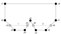
- the conventional bending simulation when two or more line segments are on one straight line as shown in Fig. 8, there is no means for simultaneously bending the sheet metal.
- the device when specifying lines for bending a planar area that divides a metal sheet, the device collectively selects multiple lines that exist on the same straight line by selecting both ends of the most extreme ends of the multiple lines.
- One aspect of the teaching method disclosed herein is a teaching method executed by a computer, in which when specifying lines for bending a planar area representing a metal sheet that divides the area, the method collectively selects multiple line segments by selecting both ends of the most extreme ends of the multiple line segments that exist on the same straight line.
- FIG. 2 is a diagram illustrating an example of a functional block configuration of a teaching device according to an embodiment.
- FIG. 13 is a diagram showing an example of a teaching screen.
- FIG. 13 is a diagram illustrating an example of vertex selection.
- FIG. 13 is a diagram illustrating an example of vertex selection.
- 4 is a flowchart illustrating a teaching process of the teaching device.
- FIG. 13 is a diagram showing an example of a teaching screen showing the shape of a metal sheet before bending;
- FIG. 13 is a diagram showing an example of designation of a line segment to be bent;
- FIG. 13 is a diagram showing an example of designation of a line segment to be bent;
- FIG. 1 is a diagram illustrating an example of a functional block configuration of a teaching device according to an embodiment.
- the teaching device 10 is a device that receives a selection of vertices from an operator on a teaching screen of CAD data showing the shape of a metal sheet in order to perform a bending simulation, and determines one or more line segments based on the selected vertices.
- the teaching device 10 is a computer, a tablet terminal, or the like, and includes a CPU 11, a storage unit 12, a display unit 13, an input unit 14, and a bus 15.
- the CPU 11 also includes a vertex acquisition unit 110 and a bend line determination unit 111.
- the storage unit 12 is a read only memory (ROM), a solid state drive (SSD), a hard disk drive (HDD), or the like, and stores CAD data 121.
- the CAD data 121 stores in advance a CAD file that is created by a CAD device (not shown) and indicates the shape of the metal sheet to be subjected to bending simulation processing.
- the storage unit 12 may store a line segment list that includes selected line segments to be bent, as described below.
- the display unit 13 is a display device such as a liquid crystal display, and displays a teaching screen that shows the CAD file of the sheet metal and instructs the lines to be bent.
- the input unit 14 is, for example, a mouse, a keyboard, or a touch panel arranged on the display unit 13, and receives input from the operator.
- the CPU 11 is a processor that provides overall control of the teaching device 10.
- the CPU 11 reads the system program stored in the memory unit 12 and the application programs stored in the various software via the bus 15, and controls the entire teaching device 10 in accordance with the system program and the application program.
- the CPU 11 is configured to realize the functions of a vertex acquisition unit 110 and a bending line determination unit 111.
- the vertex acquisition unit 110 when the vertex acquisition unit 110 receives a teaching instruction for a line segment to be bent, including a designation of a metal sheet, based on an input operation of an operator via the input unit 14, the vertex acquisition unit 110 reads a CAD file indicating the shape of the designated metal sheet from the CAD data 121.
- the vertex acquisition unit 110 displays the read CAD file on the display unit 13 as a teaching screen.
- 2 is a diagram showing an example of a teaching screen, in which the shape of the metal sheet is the same as that in FIG.
- the vertex acquiring unit 110 acquires, for a planar area representing the sheet metal on the teaching screen, vertices J3 and J6, which are the two ends of a line segment that performs bending processing and divides the area, based on, for example, an input operation by an operator via the input unit 14.
- the vertex acquiring unit 110 outputs the acquired vertex J3 and vertex J6 to a bending line determining unit 111, which will be described later.
- the bend line determination unit 111 determines a line segment having the acquired vertex J3 as a start point and the acquired vertex J6 as an end point, for example, as shown in Fig. 3. However, as shown in Fig. 3, among the line segments connecting the vertices J3 and J6, the line segment connecting the vertices J3' and J6' is not inside the sheet metal area, but the line segment connecting the vertices J3 and J3' and the line segment connecting the vertices J6' and J6 are on the same straight line, and the area connecting the vertices J3, J4, J4', and J3' and the area connecting the vertices J6', J5', J5, and J6 are common to the sheet metal area, so the bend line determination unit 111 collectively selects the line segments J3J3' and J6'J6 to be bent at the same time.
- the bend line determination unit 111 may add the collectively selected line segments J3J3' and J6'J6 to a line segment list (not shown) stored in the storage unit 12. In this way, the teaching device 10 can select a vertex of a line segment only once, instead of selecting the vertex multiple times, and can collectively select multiple line segments to be bent at the same time.
- bending line determination unit 111 determines that vertex J3' cannot be selected because the area including vertex J3' is not a line segment but is only a point. In this case, bending line determination unit 111 may display an error indicating that selection is not possible on display unit 13.
- FIG. 5 is a flowchart illustrating the teaching process of the teaching device 10. The flow shown here is executed every time a teaching instruction is received from an operator.
- step S11 when the vertex acquisition unit 110 receives an instruction from the operator to teach the line segment to be bent, including the designation of the sheet metal, it reads a CAD file indicating the shape of the specified sheet metal from the CAD data 121, and displays the read CAD file as a teaching screen on the display unit 13. Based on the input operation of the operator via the input unit 14, the vertex acquisition unit 110 acquires two vertices that are the two ends of the line segment to be bent, which divides the planar area representing the sheet metal on the teaching screen.
- step S12 the bend line determination unit 111 determines whether the positions of the two vertices acquired in step S11 are different. If the positions of the two vertices are different, the process proceeds to step S13. On the other hand, if the positions of the two vertices are the same, the process proceeds to step S17.
- step S13 the bend line determination unit 111 determines whether one or more line segments connecting the two vertices are collinear and whether the area containing each of the two vertices is common to the sheet metal area. If one or more line segments connecting the two vertices are collinear and the area containing each of the two vertices is common to the sheet metal area, processing proceeds to step S14. On the other hand, if one or more line segments connecting the two vertices are not collinear or the area containing each of the two vertices is not common to the sheet metal area, processing proceeds to step S17.
- step S14 the bend line determination unit 111 determines whether or not one or more line segments connecting the two vertices intersect with an already selected line segment. If one or more line segments connecting the two vertices intersect with an already selected line segment, the process proceeds to step S17. On the other hand, if one or more line segments connecting the two vertices do not intersect with an already selected line segment, the process proceeds to step S15.
- step S15 the bend line determination unit 111 adds the selected line segment or segments to a line segment list (not shown).
- step S16 the bend line determination unit 111 displays on the display unit 13 whether or not to add a line segment, and determines whether or not an additional instruction has been received from the operator via the input unit 14. If an additional instruction has been received from the operator, the process returns to step S11. On the other hand, if an end instruction has been received from the operator, the teaching device 10 ends the teaching process. Then, the teaching device 10 outputs the line segment list to an external device that executes the bending process simulation.
- step S17 the bend line determination unit 111 displays an error indicating that the selection is not possible on the display unit 13.
- the teaching device 10 ends the teaching process.
- the teaching device 10 can collectively select multiple line segments that are arranged on a single straight line and are to be bent simultaneously as a pre-processing step for bending simulation.
- the teaching device 10 is a device different from an external device (not shown) that executes a bending simulation, but the present invention is not limited to this.
- the teaching device 10 may be included in an external device (not shown) that executes a bending simulation.
- each function included in the teaching device 10 can be realized by hardware, software, or a combination of these.
- being realized by software means being realized by a computer reading and executing a program.
- Non-transitory computer readable media include various types of tangible storage media. Examples of non-transitory computer readable media include magnetic recording media (e.g., flexible disks, magnetic tapes, hard disk drives), magneto-optical recording media (e.g., magneto-optical disks), CD-ROMs (Read Only Memory), CD-Rs, CD-R/Ws, and semiconductor memories (e.g., mask ROMs, PROMs (Programmable ROMs), EPROMs (Erasable PROMs), flash ROMs, RAMs).
- the program may also be provided to the computer by various types of temporary computer readable media. Examples of temporary computer readable media include electrical signals, optical signals, and electromagnetic waves.
- the temporary computer readable medium can provide the program to the computer via a wired communication path such as an electric wire or optical fiber, or via a wireless communication path.
- the step of writing the program to be recorded on the recording medium includes not only processes that are performed chronologically according to the order, but also processes that are not necessarily performed chronologically but are executed in parallel or individually.
- the step of writing the program may also be performed by cloud computing.
Landscapes
- Engineering & Computer Science (AREA)
- Physics & Mathematics (AREA)
- Geometry (AREA)
- General Physics & Mathematics (AREA)
- Mechanical Engineering (AREA)
- Theoretical Computer Science (AREA)
- Mathematical Analysis (AREA)
- Computational Mathematics (AREA)
- Human Computer Interaction (AREA)
- Mathematical Optimization (AREA)
- Pure & Applied Mathematics (AREA)
- Computer Hardware Design (AREA)
- Evolutionary Computation (AREA)
- General Engineering & Computer Science (AREA)
- Architecture (AREA)
- Bending Of Plates, Rods, And Pipes (AREA)
- Numerical Control (AREA)
- Manipulator (AREA)
Abstract
曲げ加工シミュレーションの前処理として、1つの直線上に配置され同時に曲げ加工を行う複数の線分を一括選択すること。 教示装置は、板金を表す平面的な領域に対し、前記領域を分割する曲げ加工を行う線分を指定するときに、同一直線上に存在する複数の線分のうち前記複数の線分の最も端の両端を選択することで前記複数の線分を一括選択する。
Description
本開示は、板金の曲げ加工の線分を指定する教示装置及び教示方法に関する。
板金を表す2次元的な多角形に対し、曲げ線(線分)を指定することによって、曲げ加工のシミュレーションを行う技術がある。その際に、曲げ線及び曲げ加工を行う順番がオペレータにより決定される。
例えば、板金部品の展開図に基づいて、板金部品を製作することが可能な複数の曲げ順候補及び、各曲げ順候補の各曲げ工程で使用される曲げ金型候補を検出し、複数の曲げ順候補を表示することにより、板金部品の曲げ順及び曲げ金型を、曲げ工場の具体的な事情に併せて最適に決定できる技術が知られている。例えば、特許文献1参照。
例えば、板金部品の展開図に基づいて、板金部品を製作することが可能な複数の曲げ順候補及び、各曲げ順候補の各曲げ工程で使用される曲げ金型候補を検出し、複数の曲げ順候補を表示することにより、板金部品の曲げ順及び曲げ金型を、曲げ工場の具体的な事情に併せて最適に決定できる技術が知られている。例えば、特許文献1参照。
ところで、従来技術では、オペレータにより曲げ線及び曲げ加工を行う順番を決定するために、CAD装置により作成された板金の形状を示すCADファイルを読み込み、読み込んだCADファイルの教示画面を液晶ディスプレイ等の表示装置に表示する。
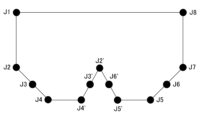
図6は、曲げ加工前の板金の形状を示す教示画面の一例を示す図である。
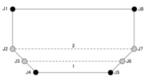
図6に示すように、曲げ加工前の板金の形状は、複数の頂点J1~J8と、頂点を両端とする複数の線分で構成された多角形である。そして、オペレータがマウスやタッチパネル等の入力装置を用いて、教示画面において2つの頂点を選択することで、板金の多角形を2つの領域に分割するように、曲げ加工する線分(曲げ線)が決定される。すなわち、従来技術では、図7に示すように、オペレータにより最初に頂点J3と頂点J6と選択され、次に頂点J2と頂点J7との線分を選択された場合、頂点J3と頂点J6とを結ぶ線分が最初に曲げる線分とし、頂点J2と頂点J7とを結ぶ線分が2番目に曲げる線分として指定される。なお、図7では、曲げる線分の順番を数字「1」、「2」で示す。そして、3次元シミュレーションによって、指定された順番に板金が曲げ加工によって変形する過程を確認するとともに、加工中に工具や板金が干渉しないかのチェック等を行う。
ところで、板金の形状が図8に示すような場合で、2つの線分が指定された場合、従来の曲げ加工シミュレーションでは、2つの曲げ線それぞれについて順番に行う必要がある。しかしながら、従来の曲げ加工シミュレーションでは、図8に示すような2以上の複数の線分が1つの直線上にある場合、同時に曲げ加工を行う手段がなかった。
図6は、曲げ加工前の板金の形状を示す教示画面の一例を示す図である。
図6に示すように、曲げ加工前の板金の形状は、複数の頂点J1~J8と、頂点を両端とする複数の線分で構成された多角形である。そして、オペレータがマウスやタッチパネル等の入力装置を用いて、教示画面において2つの頂点を選択することで、板金の多角形を2つの領域に分割するように、曲げ加工する線分(曲げ線)が決定される。すなわち、従来技術では、図7に示すように、オペレータにより最初に頂点J3と頂点J6と選択され、次に頂点J2と頂点J7との線分を選択された場合、頂点J3と頂点J6とを結ぶ線分が最初に曲げる線分とし、頂点J2と頂点J7とを結ぶ線分が2番目に曲げる線分として指定される。なお、図7では、曲げる線分の順番を数字「1」、「2」で示す。そして、3次元シミュレーションによって、指定された順番に板金が曲げ加工によって変形する過程を確認するとともに、加工中に工具や板金が干渉しないかのチェック等を行う。
ところで、板金の形状が図8に示すような場合で、2つの線分が指定された場合、従来の曲げ加工シミュレーションでは、2つの曲げ線それぞれについて順番に行う必要がある。しかしながら、従来の曲げ加工シミュレーションでは、図8に示すような2以上の複数の線分が1つの直線上にある場合、同時に曲げ加工を行う手段がなかった。
そこで、曲げ加工シミュレーションの前処理として、1つの直線上に配置され同時に曲げ加工を行う複数の線分を一括選択することが望まれている。
本開示の教示装置の一態様は、板金を表す平面的な領域に対し、前記領域を分割する曲げ加工を行う線分を指定するときに、同一直線上に存在する複数の線分のうち前記複数の線分の最も端の両端を選択することで前記複数の線分を一括選択する。
本開示の教示方法の一態様は、コンピュータにより実行される教示方法であって、板金を表す平面的な領域に対し、前記領域を分割する曲げ加工を行う線分を指定するときに、同一直線上に存在する複数の線分のうち前記複数の線分の最も端の両端を選択することで前記複数の線分を一括選択する。
以下、一実施形態に係る教示装置について、図を参照しながら詳細に説明する。
図1は、一実施形態に係る教示装置の機能ブロックの構成の一例を示す図である。
教示装置10は、曲げ加工シミュレーションを行うために、板金の形状を示すCADデータの教示画面において、オペレータから頂点の選択を受け付けて、選択された頂点に基づいて1又は複数の線分を決定する装置である。図1に示すように、教示装置10は、コンピュータやタブレット端末等であり、CPU11、記憶部12、表示部13、入力部14、及びバス15を含む。また、CPU11は、頂点取得部110、及び曲げ線決定部111を含む。
図1は、一実施形態に係る教示装置の機能ブロックの構成の一例を示す図である。
教示装置10は、曲げ加工シミュレーションを行うために、板金の形状を示すCADデータの教示画面において、オペレータから頂点の選択を受け付けて、選択された頂点に基づいて1又は複数の線分を決定する装置である。図1に示すように、教示装置10は、コンピュータやタブレット端末等であり、CPU11、記憶部12、表示部13、入力部14、及びバス15を含む。また、CPU11は、頂点取得部110、及び曲げ線決定部111を含む。
記憶部12は、ROM(Read Only Memory)、SSD(Solid State Drive)、HDD(Hard Disk Drive)等であり、CADデータ121を記憶する。
CADデータ121には、図示しないCAD装置等により作成され、曲げ加工シミュレーション処理を行う板金の形状を示すCADファイルが予め記憶される。
なお、記憶部12には、後述するように、選択された曲げ加工する線分を格納する線分リストが記憶されてもよい。
CADデータ121には、図示しないCAD装置等により作成され、曲げ加工シミュレーション処理を行う板金の形状を示すCADファイルが予め記憶される。
なお、記憶部12には、後述するように、選択された曲げ加工する線分を格納する線分リストが記憶されてもよい。
表示部13は、液晶ディスプレイ等の表示装置であり、板金のCADファイルを表示し曲げ加工する線分を教示する教示画面を表示する。
入力部14は、例えば、マウスやキーボード、表示部13に配置されたタッチパネル等であり、オペレータからの入力を受け付ける。
CPU11は、教示装置10を全体的に制御するプロセッサである。CPU11は、記憶部12に格納されたシステムプログラム及び各種ソフトウェアに格納されたアプリケーションプログラムを、バス15を介して読み出し、システムプログラム及びアプリケーションプログラムに従って教示装置10全体を制御する。これにより、図1に示すように、CPU11が、頂点取得部110、及び曲げ線決定部111の機能を実現するように構成される。
頂点取得部110は、例えば、入力部14を介したオペレータの入力操作に基づいて、板金の指定を含む曲げ加工する線分の教示指示を受け付けた場合、指定された板金の形状を示すCADファイルをCADデータ121から読み込む。頂点取得部110は、読み込んだCADファイルを教示画面として表示部13に表示する。
図2は、教示画面の一例を示す図である。図2では、板金の形状は図8と同じである。
具体的には、頂点取得部110は、例えば、入力部14を介したオペレータの入力操作に基づいて、教示画面の板金を表す平面的な領域に対し、領域を分割する曲げ加工を行う線分の最も端の両端である頂点J3と頂点J6とを取得する。頂点取得部110は、取得した頂点J3及び頂点J6を後述する曲げ線決定部111に出力する。
図2は、教示画面の一例を示す図である。図2では、板金の形状は図8と同じである。
具体的には、頂点取得部110は、例えば、入力部14を介したオペレータの入力操作に基づいて、教示画面の板金を表す平面的な領域に対し、領域を分割する曲げ加工を行う線分の最も端の両端である頂点J3と頂点J6とを取得する。頂点取得部110は、取得した頂点J3及び頂点J6を後述する曲げ線決定部111に出力する。
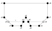
曲げ線決定部111は、例えば、図3に示すように、取得された頂点J3を始点とし、取得された頂点J6を終点とする線分と決定する。ただし、図3に示すように、頂点J3と頂点J6とを結ぶ線分のうち頂点J3´と頂点J6´とを結ぶ線分が板金の領域内部にないが、頂点J3と頂点J3´とを結ぶ線分、及び頂点J6´と頂点J6とを結ぶ線分が同一直線上にあり、頂点J3、J4、J4´、J3´を結ぶ領域及び頂点J6´、J5´、J5、J6を結ぶ領域が板金の領域と共通であることから、曲げ線決定部111は、同時に曲げ加工する線分J3J3´と線分J6´J6とを一括選択する。曲げ線決定部111は、一括選択した線分J3J3´と線分J6´J6を記憶部12に記憶される図示しない線分リストに追加するようにしてもよい。
そうすることで、教示装置10は、複数回選択する必要があった線分を1回の頂点の選択で済ますことができ、同時に曲げ加工する複数の線分を一括選択することができる。
そうすることで、教示装置10は、複数回選択する必要があった線分を1回の頂点の選択で済ますことができ、同時に曲げ加工する複数の線分を一括選択することができる。
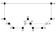
なお、例えば、図4に示すように、頂点取得部110により頂点J3´と頂点J6とが選択された場合、曲げ線決定部111は、頂点J3´を含む領域が線分ではなく点のみであることから、選択不可と判定する。この場合、曲げ線決定部111は、選択不可のエラーを表示部13に表示するようにしてもよい。
<教示装置10の教示処理>
次に、図5を参照しながら、教示装置10の教示処理の流れを説明する。
図5は、教示装置10の教示処理について説明するフローチャートである。ここで示すフローは、オペレータから教示指示を受け付ける度に実行される。
次に、図5を参照しながら、教示装置10の教示処理の流れを説明する。
図5は、教示装置10の教示処理について説明するフローチャートである。ここで示すフローは、オペレータから教示指示を受け付ける度に実行される。
ステップS11において、頂点取得部110は、オペレータから板金の指定を含む曲げ加工する線分の教示指示を受け付けた場合、指定された板金の形状を示すCADファイルをCADデータ121から読み込み、読み込んだCADファイルを教示画面として表示部13に表示する。頂点取得部110は、入力部14を介したオペレータの入力操作に基づいて、教示画面の板金を表す平面的な領域に対し、領域を分割する曲げ加工を行う線分の最も端の両端となる2つの頂点を取得する。
ステップS12において、曲げ線決定部111は、ステップS11で取得された2つの頂点の位置が異なるか否かを判定する。2つの頂点の位置が異なる場合、処理はステップS13に進む。一方、2つの頂点の位置が同じ場合、処理はステップS17に進む。
ステップS13において、曲げ線決定部111は、2つの頂点を結ぶ1又は複数の線分が同一直線上にあり、2つの頂点それぞれが含まれる領域が板金の領域と共通するか否かを判定する。2つの頂点を結ぶ1又は複数の線分が同一直線上にあり、2つの頂点それぞれが含まれる領域が板金の領域と共通する場合、処理はステップS14に進む。一方、2つの頂点を結ぶ1又は複数の線分が同一直線上にない、又は2つの頂点それぞれが含まれる領域が板金の領域と共通しない場合、処理はステップS17に進む。
ステップS14において、曲げ線決定部111は、2つの頂点を結ぶ1又は複数の線分が既に選択した線分と交差するか否かを判定する。2つの頂点を結ぶ1又は複数の線分が既に選択した線分と交差する場合、処理はステップS17に進む。一方、2つの頂点を結ぶ1又は複数の線分が既に選択した線分と交差しない場合、処理はステップS15に進む。
ステップS15において、曲げ線決定部111は、選択した1又は複数の線分を線分リスト(図示しない)に追加する。
ステップS16において、曲げ線決定部111は、線分を追加するか否かを表示部13に表示し、入力部14を介してオペレータより追加指示を受け付けたか否かを判定する。オペレータより追加指示を受け付けた場合、処理はステップS11に戻る。一方、オペレータより終了指示を受け付けた場合、教示装置10は、教示処理を終了する。そして、教示装置10は、線分リストを曲げ加工シミュレーションを実行する外部装置に出力する。
ステップS17において、曲げ線決定部111は、選択不可のエラーを表示部13に表示する。教示装置10は、教示処理を終了する。
以上により、一実施形態に係る教示装置10は、曲げ加工シミュレーションの前処理として、1つの直線上に配置され同時に曲げ加工を行う複数の線分を一括選択することができる。
<変形例>
一実施形態では、教示装置10は、曲げ加工シミュレーションを実行する外部装置(図示しない)と異なる装置としたが、これに限定されない。
例えば、教示装置10は、曲げ加工シミュレーションを実行する外部装置(図示しない)に含まれてもよい。
一実施形態では、教示装置10は、曲げ加工シミュレーションを実行する外部装置(図示しない)と異なる装置としたが、これに限定されない。
例えば、教示装置10は、曲げ加工シミュレーションを実行する外部装置(図示しない)に含まれてもよい。
なお、一実施形態における、教示装置10に含まれる各機能は、ハードウェア、ソフトウェア又はこれらの組み合わせによりそれぞれ実現することができる。ここで、ソフトウェアによって実現されるとは、コンピュータがプログラムを読み込んで実行することにより実現されることを意味する。
プログラムは、様々なタイプの非一時的なコンピュータ可読媒体(Non-transitory computer readable medium)を用いて格納され、コンピュータに供給することができる。非一時的なコンピュータ可読媒体は、様々なタイプの実体のある記録媒体(Tangible storage medium)を含む。非一時的なコンピュータ可読媒体の例は、磁気記録媒体(例えば、フレキシブルディスク、磁気テープ、ハードディスクドライブ)、光磁気記録媒体(例えば、光磁気ディスク)、CD-ROM(Read Only Memory)、CD-R、CD-R/W、半導体メモリ(例えば、マスクROM、PROM(Programmable ROM)、EPROM(Erasable PROM)、フラッシュROM、RAM)を含む。また、プログラムは、様々なタイプの一時的なコンピュータ可読媒体(Transitory computer readable medium)によってコンピュータに供給されてもよい。一時的なコンピュータ可読媒体の例は、電気信号、光信号、及び電磁波を含む。一時的なコンピュータ可読媒体は、電線及び光ファイバ等の有線通信路、又は、無線通信路を介して、プログラムをコンピュータに供給できる。
なお、記録媒体に記録されるプログラムを記述するステップは、その順序に沿って時系列的に行われる処理はもちろん、必ずしも時系列的に処理されなくとも、並列的あるいは個別に実行される処理をも含むものである。また、前記プログラムを記述するステップはクラウドコンピューティングで実施してもよい。
本開示について詳述したが、本開示は上述した個々の実施形態に限定されるものではない。これらの実施形態は、本開示の要旨を逸脱しない範囲で、又は、特許請求の範囲に記載された内容とその均等物から導き出される本開示の趣旨を逸脱しない範囲で、種々の追加、置き換え、変更、部分的削除等が可能である。また、これらの実施形態は、組み合わせて実施することもできる。例えば、上述した実施形態において、各動作の順序や各処理の順序は、一例として示したものであり、これらに限定されるものではない。また、上述した実施形態の説明に数値又は数式が用いられている場合も同様である。
上記実施形態及び変形例に関し、さらに以下の付記を開示する。
(付記1)
教示装置(10)は、板金を表す平面的な領域に対し、領域を分割する曲げ加工を行う線分を指定するときに、同一直線上に存在する複数の線分のうち複数の線分の最も端の両端を選択することで複数の線分を一括選択する。
(付記2)
教示方法は、コンピュータにより実行される教示方法であって、板金を表す平面的な領域に対し、領域を分割する曲げ加工を行う線分を指定するときに、同一直線上に存在する複数の線分のうち複数の線分の最も端の両端を選択することで複数の線分を一括選択する。
(付記1)
教示装置(10)は、板金を表す平面的な領域に対し、領域を分割する曲げ加工を行う線分を指定するときに、同一直線上に存在する複数の線分のうち複数の線分の最も端の両端を選択することで複数の線分を一括選択する。
(付記2)
教示方法は、コンピュータにより実行される教示方法であって、板金を表す平面的な領域に対し、領域を分割する曲げ加工を行う線分を指定するときに、同一直線上に存在する複数の線分のうち複数の線分の最も端の両端を選択することで複数の線分を一括選択する。
10 教示装置
11 CPU
110 頂点取得部
111 曲げ線決定部
12 記憶部
121 CADデータ
13 表示部
14 入力部
11 CPU
110 頂点取得部
111 曲げ線決定部
12 記憶部
121 CADデータ
13 表示部
14 入力部
Claims (2)
- 板金を表す平面的な領域に対し、前記領域を分割する曲げ加工を行う線分を指定するときに、同一直線上に存在する複数の線分のうち前記複数の線分の最も端の両端を選択することで前記複数の線分を一括選択する、教示装置。
- コンピュータにより実行される教示方法であって、
板金を表す平面的な領域に対し、前記領域を分割する曲げ加工を行う線分を指定するときに、同一直線上に存在する複数の線分のうち前記複数の線分の最も端の両端を選択することで前記複数の線分を一括選択する、教示方法。
Priority Applications (5)
| Application Number | Priority Date | Filing Date | Title |
|---|---|---|---|
| JP2025541202A JPWO2025041248A1 (ja) | 2023-08-22 | 2023-08-22 | |
| CN202380101406.6A CN121713182A (zh) | 2023-08-22 | 2023-08-22 | 示教装置以及示教方法 |
| PCT/JP2023/030093 WO2025041248A1 (ja) | 2023-08-22 | 2023-08-22 | 教示装置及び教示方法 |
| DE112023006531.4T DE112023006531T5 (de) | 2023-08-22 | 2023-08-22 | Lehrvorrichtung und lehrmethode |
| TW113128081A TW202508732A (zh) | 2023-08-22 | 2024-07-29 | 教示裝置及教示方法 |
Applications Claiming Priority (1)
| Application Number | Priority Date | Filing Date | Title |
|---|---|---|---|
| PCT/JP2023/030093 WO2025041248A1 (ja) | 2023-08-22 | 2023-08-22 | 教示装置及び教示方法 |
Publications (1)
| Publication Number | Publication Date |
|---|---|
| WO2025041248A1 true WO2025041248A1 (ja) | 2025-02-27 |
Family
ID=94731830
Family Applications (1)
| Application Number | Title | Priority Date | Filing Date |
|---|---|---|---|
| PCT/JP2023/030093 Pending WO2025041248A1 (ja) | 2023-08-22 | 2023-08-22 | 教示装置及び教示方法 |
Country Status (5)
| Country | Link |
|---|---|
| JP (1) | JPWO2025041248A1 (ja) |
| CN (1) | CN121713182A (ja) |
| DE (1) | DE112023006531T5 (ja) |
| TW (1) | TW202508732A (ja) |
| WO (1) | WO2025041248A1 (ja) |
Citations (2)
| Publication number | Priority date | Publication date | Assignee | Title |
|---|---|---|---|---|
| JPH11202919A (ja) * | 1998-01-07 | 1999-07-30 | Shigeru Aomura | 板金cad図面からの立体図作成方法及びそのプログラムを記憶した記憶媒体 |
| JP2008151606A (ja) * | 2006-12-15 | 2008-07-03 | Juki Corp | 画像処理方法および画像処理装置 |
Family Cites Families (1)
| Publication number | Priority date | Publication date | Assignee | Title |
|---|---|---|---|---|
| JP3696781B2 (ja) | 2000-09-05 | 2005-09-21 | 株式会社アマダ | 板金部品の曲げ順及び曲げ金型提案装置及び提案方法 |
-
2023
- 2023-08-22 WO PCT/JP2023/030093 patent/WO2025041248A1/ja active Pending
- 2023-08-22 CN CN202380101406.6A patent/CN121713182A/zh active Pending
- 2023-08-22 DE DE112023006531.4T patent/DE112023006531T5/de active Pending
- 2023-08-22 JP JP2025541202A patent/JPWO2025041248A1/ja active Pending
-
2024
- 2024-07-29 TW TW113128081A patent/TW202508732A/zh unknown
Patent Citations (2)
| Publication number | Priority date | Publication date | Assignee | Title |
|---|---|---|---|---|
| JPH11202919A (ja) * | 1998-01-07 | 1999-07-30 | Shigeru Aomura | 板金cad図面からの立体図作成方法及びそのプログラムを記憶した記憶媒体 |
| JP2008151606A (ja) * | 2006-12-15 | 2008-07-03 | Juki Corp | 画像処理方法および画像処理装置 |
Non-Patent Citations (2)
| Title |
|---|
| "Master AutoCAD Perfect Book Trouble! & All Useful Tricks, first edition", 21 March 2018, IMPRESS HOLDINGS, INC., JP, ISBN: 978-4-295-00336-6, article YANO, ETSUKO ET AL.: "Linking More than One Collinear Line Segment", pages: 158, XP009561952 * |
| KOGUCHI, ATSUSHI : " Automated Process Planning for Sheet Metal Bending by Handling Robot - Process Planning Method by Taking Critical Dimension into Account ", JOURNAL OF THE JAPAN SOCIETY OF PRECISION ENGINEERING, vol. 68, no. 4, 5 April 2002 (2002-04-05), pages 602 - 607, XP093282097 * |
Also Published As
| Publication number | Publication date |
|---|---|
| CN121713182A (zh) | 2026-03-20 |
| DE112023006531T5 (de) | 2026-05-21 |
| TW202508732A (zh) | 2025-03-01 |
| JPWO2025041248A1 (ja) | 2025-02-27 |
Similar Documents
| Publication | Publication Date | Title |
|---|---|---|
| JP2010009342A (ja) | 多目的最適化設計の設計改善支援装置、方法、及びプログラム | |
| US11314230B2 (en) | Machining program generation support device | |
| JP2014106928A (ja) | 試験方法、試験プログラム、および、試験制御装置 | |
| JP4983546B2 (ja) | 業務フローチャート作成プログラムおよび業務フローチャート作成装置 | |
| JP6150953B2 (ja) | デバッグ装置、デバッグ方法及びデバッグプログラム | |
| JP3805776B2 (ja) | グラフィカルプログラミング装置及びプログラマブル表示器 | |
| US20150363514A1 (en) | CAD Data Processing Device and Processing Method | |
| WO2020194455A1 (ja) | テストケース生成装置、テストケース生成方法、およびテストケース生成プログラム | |
| KR102466551B1 (ko) | 데이터 기록 방법, 장치 및 전자 기기 | |
| CN120068191A (zh) | 显示方法及装置 | |
| KR20250141736A (ko) | 컴퓨터 프로그램, 정보 처리 방법 및 정보 처리 장치 | |
| JP5543177B2 (ja) | 変動数値予測システム及び変動数値予測方法 | |
| TW202508732A (zh) | 教示裝置及教示方法 | |
| JP2010117765A (ja) | ワイヤーハーネスの可動経路解析システム | |
| JP7407787B2 (ja) | 情報処理装置、情報処理方法及びプログラム | |
| US20070232120A1 (en) | Design support system, design support method, and program | |
| US20210350296A1 (en) | Productivity improvement support system and productivity improvement support method | |
| US10914580B2 (en) | Measurement system, measurement program, and control method | |
| JP7411182B2 (ja) | 医用画像処理装置、医用画像処理方法、医用画像処理プログラム、及び手術支援システム | |
| JP5264305B2 (ja) | 回路編集支援方法、そのプログラム、その記録媒体、および回路編集支援装置 | |
| WO2020031903A1 (ja) | サポート装置およびサポートプログラム | |
| WO2025017786A1 (ja) | Plc装置 | |
| JP2007240848A (ja) | 表示プログラム、データ構造及び表示装置 | |
| JP5028644B2 (ja) | 電子式計算機および計算機制御プログラム | |
| JP4824065B2 (ja) | 支持点回転角度を考慮可能なワイヤーハーネスの変形解析システム |
Legal Events
| Date | Code | Title | Description |
|---|---|---|---|
| 121 | Ep: the epo has been informed by wipo that ep was designated in this application |
Ref document number: 23949709 Country of ref document: EP Kind code of ref document: A1 |
|
| ENP | Entry into the national phase |
Ref document number: 2025541202 Country of ref document: JP Kind code of ref document: A |
|
| WWE | Wipo information: entry into national phase |
Ref document number: 2025541202 Country of ref document: JP |
|
| WWE | Wipo information: entry into national phase |
Ref document number: 112023006531 Country of ref document: DE |