WO2025041238A1 - Dispositif de détection d'anomalies, dispositif de commande, procédé de détection d'anomalies, programme, et système de détection d'anomalies intégré - Google Patents
Dispositif de détection d'anomalies, dispositif de commande, procédé de détection d'anomalies, programme, et système de détection d'anomalies intégré Download PDFInfo
- Publication number
- WO2025041238A1 WO2025041238A1 PCT/JP2023/030051 JP2023030051W WO2025041238A1 WO 2025041238 A1 WO2025041238 A1 WO 2025041238A1 JP 2023030051 W JP2023030051 W JP 2023030051W WO 2025041238 A1 WO2025041238 A1 WO 2025041238A1
- Authority
- WO
- WIPO (PCT)
- Prior art keywords
- feature
- unit
- fluctuation pattern
- industrial machine
- feature model
- Prior art date
- Legal status (The legal status is an assumption and is not a legal conclusion. Google has not performed a legal analysis and makes no representation as to the accuracy of the status listed.)
- Pending
Links
Images


Classifications
-
- G—PHYSICS
- G05—CONTROLLING; REGULATING
- G05B—CONTROL OR REGULATING SYSTEMS IN GENERAL; FUNCTIONAL ELEMENTS OF SUCH SYSTEMS; MONITORING OR TESTING ARRANGEMENTS FOR SUCH SYSTEMS OR ELEMENTS
- G05B23/00—Testing or monitoring of control systems or parts thereof
- G05B23/02—Electric testing or monitoring
- G05B23/0205—Electric testing or monitoring by means of a monitoring system capable of detecting and responding to faults
- G05B23/0218—Electric testing or monitoring by means of a monitoring system capable of detecting and responding to faults characterised by the fault detection method dealing with either existing or incipient faults
- G05B23/0224—Process history based detection method, e.g. whereby history implies the availability of large amounts of data
- G05B23/024—Quantitative history assessment, e.g. mathematical relationships between available data; Functions therefor; Principal component analysis [PCA]; Partial least square [PLS]; Statistical classifiers, e.g. Bayesian networks, linear regression or correlation analysis; Neural networks
Definitions
- This disclosure relates to an anomaly detection device, a control device, an anomaly detection method, a program, and an integrated anomaly detection system that detects anomalies in the features of industrial machinery based on the variation patterns of the features.
- measurement data shows that changes in the behavior of industrial machines such as machine tools are not as simple as dividing them into two categories based on a threshold.
- a threshold For example, when changes in evaluation values are viewed over time, they may change in a step-like manner or fluctuate up and down.
- the conventional method of notifying an abnormality when the evaluation value exceeds a predefined threshold results in frequent notifications, which does not lead to meaningful decision-making for the operator. Adjusting the threshold does not fundamentally solve the problem of the difficulty in distinguishing between normal and abnormal.
- the behavior of industrial machinery is unique. Therefore, it is difficult to create and apply general-purpose models and thresholds from large amounts of data in advance. Because the general mechanisms behind failures in industrial machinery such as machine tools have not been fully elucidated, the role required of anomaly detection devices is to match data anomalies with industrial machinery anomalies as closely as possible.
- One aspect of the anomaly detection device disclosed herein includes a feature acquisition unit that acquires a context in the production operation of an industrial machine and a state quantity related to the production operation state of the industrial machine, and acquires feature quantities related to the production operation state of the industrial machine based on the acquired context and the state quantity; a feature model operation unit that generates, updates, deletes, and adds feature models based on the context and the feature quantities; a feature model storage unit that stores the feature models generated by the feature model operation unit; an inference calculation unit that calculates an evaluation value of the operating state of the industrial machine based on the feature quantities and the feature models; a fluctuation pattern management unit that stores and manages a predetermined fluctuation pattern of the evaluation value; a fluctuation pattern classification unit that classifies the fluctuation pattern of the evaluation value of the operating state of the industrial machine based on the calculation result of the inference calculation unit and the predetermined fluctuation pattern stored in the fluctuation pattern management unit; and a feature anomaly determination unit that determines whether the feature quantities of the industrial machine are abnormal based on
- One aspect of the control device disclosed herein is a control device that controls a motor that drives a mechanism of an industrial machine, and is equipped with the anomaly detection device of (1).
- One aspect of the anomaly detection method disclosed herein is an anomaly detection method that causes a computer to operate as an anomaly detection device, and includes a feature acquisition process for acquiring a context in the production operation of an industrial machine and a state quantity related to the production operation state of the industrial machine, and acquiring feature quantities related to the production operation state of the industrial machine based on the acquired context and the state quantity; a feature model operation process for generating, updating, deleting, and adding a feature model based on the context and the feature quantities; a feature model storage process for storing the feature model generated in the feature model operation process; an inference calculation process for calculating an evaluation value of the operating state of the industrial machine based on the feature quantities and the feature model; a fluctuation pattern management process for storing and managing a predetermined fluctuation pattern of the evaluation value; a fluctuation pattern classification process for classifying the fluctuation pattern of the evaluation value of the operating state of the industrial machine based on the calculation result of the inference calculation process and the predetermined fluctuation pattern stored in the fluctuation pattern management process; and
- One aspect of the program disclosed herein is a program that causes a computer to realize a feature acquisition process for acquiring a context in the production operation of an industrial machine and a state quantity related to the production operation state of the industrial machine, and acquiring feature quantities related to the production operation state of the industrial machine based on the acquired context and the state quantity; a feature model operation process for generating, updating, deleting, and adding a feature model based on the context and the feature quantities; a feature model storage process for storing the feature model generated in the feature model operation process; an inference calculation process for calculating an evaluation value of the operating state of the industrial machine based on the feature quantities and the feature model; a fluctuation pattern management process for storing and managing a predetermined fluctuation pattern of the evaluation value; a fluctuation pattern classification process for classifying the fluctuation pattern of the evaluation value of the operating state of the industrial machine based on the calculation result of the inference calculation process and the predetermined fluctuation pattern stored in the fluctuation pattern management process; and a feature abnormality determination process for determining whether or not
- One aspect of the integrated anomaly detection system disclosed herein includes two or more anomaly detection devices according to (1), and the fluctuation pattern management unit is shared in part or in whole between the anomaly detection devices, and the fluctuation pattern detected by one anomaly detection device is used by the other anomaly detection devices.
- FIG. 2 is a diagram illustrating an example of a hardware configuration when an anomaly detection device according to the first embodiment is connected to a numerical control device.
- FIG. 1 is a schematic functional block diagram when an anomaly detection device according to a first embodiment is connected to a numerical control device.
- FIG. 13 is a diagram showing an example of time-series data of the speed and torque of a spindle motor to which a tool is attached in a machine tool when not cutting, as a state quantity acquired by a state quantity acquisition unit.
- FIG. 11 is a diagram illustrating an example of the operation of a feature creation unit.
- FIG. 13 is a diagram illustrating an example of a relationship between a feature model and a feature amount.
- FIG. 13 is a diagram illustrating an example of a relationship between a feature model and a feature amount.
- FIG. 13 is a diagram showing an example of a predetermined variation pattern.
- FIG. 13 is a diagram showing an example of a predetermined variation pattern.
- FIG. 13 is a diagram showing an example of a predetermined variation pattern.
- FIG. 13 is a diagram showing an example of a predetermined variation pattern.
- FIG. 11 is a diagram showing an example of time-series data of evaluation values calculated by an inference calculation unit.
- 11 is a flowchart illustrating an abnormality detection process of the abnormality detection device.
- FIG. 11 is a schematic functional block diagram when an anomaly detection device according to a second embodiment is connected to a numerical control device.
- FIG. 11 is a schematic functional block diagram when an anomaly detection device according to a second embodiment is connected to a numerical control device.
- FIG. 13 is a diagram showing an example of how to select data used in machine learning in the case of the “stiffness type.”
- FIG. 13 is a diagram showing an example of how to select data used in machine learning in the case of the “rising pause pattern.”
- 11 is a flowchart illustrating an abnormality detection process of the abnormality detection device.
- FIG. 1 is a diagram illustrating an example of a hardware configuration when an anomaly detection device according to the first embodiment is connected to a numerical control device.
- the abnormality detection device 20 is connected to a numerical control device 10 .
- the numerical control device 10 and the anomaly detection device 20 are directly connected to each other via a connection interface (not shown).
- the numerical control device 10 and the anomaly detection device 20 may be connected to each other and communicate with each other via a network (not shown) such as a local area network (LAN) or the Internet. Furthermore, the numerical control device 10 and the anomaly detection device 20 are described as being different devices, but as will be described later, the anomaly detection device 20 may be included in the numerical control device 10.
- a network not shown
- LAN local area network
- the anomaly detection device 20 may be included in the numerical control device 10.
- the numerical control device 10 is, for example, a numerical control device known to those skilled in the art for controlling the operation of a machine tool (not shown). In addition, if the machine tool (not shown) is a robot or the like, the numerical control device 10 may be a robot control device or the like.
- the numerical control device 10 includes a central processing unit (CPU) 11, a read only memory (ROM) 12, a random access memory (RAM) 13, an axis control circuit 14, a servo amplifier 15, an interface (INT) 16, and a bus 17.
- the numerical control device 10 is also connected to a display 130.
- the CPU 11 is a processor that performs overall control of the numerical control device 10.
- the CPU 11 reads out a system program stored in the ROM 12 via the bus 17, and controls the entire numerical control device 10 in accordance with the system program.
- the RAM 13 temporarily stores temporary calculation data, display data, and various data input by an operator via an input device (not shown), such as a keyboard or a touch panel.
- the axis control circuit 14 receives an axis movement command from the CPU 11 via the bus 17 and outputs the command to the servo amplifier 15.
- the servo amplifier 15 drives a motor 120 that moves an axis of the machine tool (not shown).
- the motor 120 of the axis has a built-in position/speed detector (not shown), and feedbacks position/speed feedback signals from the position/speed detector to the axis control circuit 14 to perform feedback control of the position/speed.
- the INTs 16 and 24 are interfaces for connecting the numerical control device 10 and the abnormality detection device 20 .
- the display 130 is, for example, a liquid crystal display or the like, and is used for operating a machine tool (not shown) that has the numerical control device 10 as a component.
- the display 130 may also display the detection results of an abnormality detection in the machine tool (not shown) by an abnormality detection device 20 (described later).
- the abnormality detection device 20 is, for example, a computer such as a personal computer, a fog computer, or a cloud server, and includes a processor 21, a ROM 22, a RAM 23, an INT 24, and a bus 25.
- the abnormality detection device 20 is also connected to a display 230.
- the processor 21 is, for example, a CPU, which reads out a system program stored in the ROM 22 and controls the entire anomaly detection device 20 in accordance with the system program.
- the RAM 23 temporarily stores temporary calculation data, display data, and various data input by an operator via an input device (not shown) such as a keyboard or a touch panel.
- the INT 24 transmits and receives various data to and from the numerical controller 10 via the INT 16 of the numerical controller 10 .
- the display 230 is a liquid crystal display or the like, and displays the results of processing by the anomaly detection device 20, etc.
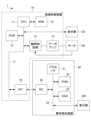
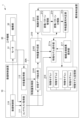
- Fig. 2 is a schematic functional block diagram of an anomaly detection device 20 according to the first embodiment connected to a machine tool 30, which is a type of industrial machine.
- Each functional block shown in Fig. 2 is realized by the CPU 11 of the numerical control device 10 shown in Fig. 1 and the processor 21 of the anomaly detection device 20 controlling the operation of each part of the device according to the respective system programs.
- the numerical control device 10 includes a numerical control unit 110, a context acquisition unit 111, and a state quantity acquisition unit 112.
- the anomaly detection device 20 includes a feature quantity acquisition unit 210, a feature model operation unit 211, an inference calculation unit 212, a variation pattern management unit 213, a variation pattern classification unit 214, a feature quantity anomaly determination unit 215, and a feature model storage unit 216.
- the feature quantity acquisition unit 210 includes a state data extraction unit 2101, and a feature quantity creation unit 2102.
- the numerical control unit 110 controls the machine tool 30 by executing a machining program stored in a memory (not shown).
- the numerical control unit 110 sequentially reads out and analyzes blocks of the machining program stored in a memory (not shown), calculates the movement amount of the motor 31 for each control cycle based on the analysis results, and controls the motor 31 according to the calculated movement amount for each control cycle.
- the machine tool 30 drives a mechanism unit 32 in the machine tool 30, which includes, for example, a ball screw used as a feed axis and a mechanism used as a main axis. In this way, the machine tool 30 machines a workpiece.
- a mechanism unit 32 in the machine tool 30, which includes, for example, a ball screw used as a feed axis and a mechanism used as a main axis. In this way, the machine tool 30 machines a workpiece.
- one motor 31 is connected to one mechanism unit 32 of the machine tool 30, but the number of motors 31 may be the same as the number of axes of the mechanism unit 32 of the
- the context acquisition unit 111 acquires the context (production status, operation status, environmental status, etc.) during production operation performed by the numerical control unit 110 (and the machine tool 30 controlled by the numerical control unit 110), and outputs the acquired context to the abnormality detection device 20.
- the context during production operation includes, for example, the operation pattern of the motor 31 during production operation (spindle speed, feed rate, etc.), the purpose of the currently performed machining (rough machining, finishing machining, etc.), the purpose of the currently performed drive of the moving part (fast forward, cutting feed, etc.), the type of tool used for machining, and work information indicating the hardness and material of the workpiece to be machined.
- the context acquisition unit 111 acquires the context during production operation that is comprehensively determined based on the machining conditions commanded by the machining program, setting information set in the numerical control unit 110 by the operator via an input device (not shown), setting information set in the numerical control unit 110 by another computer connected via a network (not shown), or information detected by devices such as sensors separately provided in the numerical control unit 110, and the values of signals acquired from a PLC (Programmable Logic Controller) (not shown).
- the context acquisition unit 111 outputs the acquired context to the feature acquisition unit 210 and feature model operation unit 211 of the anomaly detection device 20, which will be described later.
- the state quantity acquisition unit 112 acquires state quantities of the production operation state by the numerical control unit 110 (and the machine tool 30 controlled by the numerical control unit 110). Examples of state quantities of the production operation state include the spindle load (current value and torque), the feed axis load (current value and torque), the spindle rotation speed, the feed axis speed, the feed axis position, the position feedback value, the temperature of the motor 31, the vibration value, and sound.
- the state quantity acquisition unit 112 also acquires, as state quantities, for example, the actual waveforms of the rotation speed and torque value of the motor 31 that drives the mechanism unit 32 of the machine tool 30 controlled by the numerical control unit 110.
- the state quantity acquisition unit 112 outputs the acquired state quantities to the feature quantity acquisition unit 210 of the abnormality detection device 20 described later.
- the feature acquisition unit 210 acquires the context of the production operation of the machine tool 30 and state quantities related to the production operation state of the machine tool 30, and acquires feature quantities related to the production operation state of the machine tool 30 based on the acquired context and state quantities.
- the feature acquisition unit 210 includes, for example, a state data extraction unit 2101 and a feature creation unit 2102 .
- the state data extraction unit 2101 extracts state data from the state quantities acquired by the state quantity acquisition unit 112, which is used for inference processing by the inference calculation unit 212 (to be described later) and feature model update processing by the feature model operation unit 211 (to be described later).
- the state data extraction unit 2101 extracts state data from the state quantities acquired by the state quantity acquisition unit 112 using a predetermined extraction pattern based on the context of the production operation input from the context acquisition unit 111, which is used for inference processing and the like.
- the extraction pattern used by the state data extraction unit 2101 is a predetermined data processing method in which parameters are determined based on the context, and may be, for example, data processing such as setting an extraction interval of time-series data obtained based on the context, selecting data, and changing the scale of the state quantities based on the context.
- the extraction pattern used by the state data extraction unit 2101 may be registered in advance in a memory by an operator.
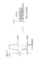
- Fig. 3 is a diagram showing an example of time series data of the speed and torque of a spindle motor to which a tool is attached in machine tool 30 that is not performing machining and is not cutting, as state quantities acquired by state quantity acquisition unit 112.
- the time series data of the speed and torque of the spindle motor is shown on the left side
- the state data of the torque extracted by state data extraction unit 2101 is shown on the right side.
- the time series data of the speed and torque of the spindle motor is data sampled at a sampling frequency of, for example, 0.001 seconds, and is time series data at a predetermined timing when the spindle motor is driven, i.e., when the spindle motor is rotating at a constant speed of about 4000 rpm and running idle.
- the status data extraction unit 2101 extracts, as status data, the torque value in a specific section of the torque time series data, for example, a section (e.g., 0.1 seconds) indicated by a dashed rectangle in which the spindle motor rotates at a constant speed of about 4000 rpm and is idling without any external force acting. As shown on the right side of Fig.
- the torque, which is the extracted status data is not a constant value but indicates minute vibrations as shown on the left side of Fig. 3.
- the status data extraction unit 2101 extracts, as status data, torques indicating minute vibrations as shown on the right side of Fig. 3 from each of the time series data of the speeds and torques of a plurality of spindle motors when the spindle motors rotate at a constant speed (e.g., about 4000 rpm, etc.) and are idling as shown on the left side of Fig. 3.
- the state data extraction unit 2101 outputs the extracted state data to the feature creation unit 2102 .
- the feature quantity creation unit 2102 creates feature quantities indicating characteristics of the operating state of the machine tool 30 controlled by the numerical control unit 110, based on the state data extracted by the state data extraction unit 2101.
- the feature quantities created by the feature quantity creation unit 2102 indicate characteristics of the operating state of the machine tool 30, and are useful information as material for making decisions when detecting an abnormality in the operating state of the machine tool 30 during production operations performed by the numerical control unit 110 (and the machine tool 30).
- the feature quantities created by the feature quantity creation unit 2102 are input data when the inference calculation unit 212, described later, performs inference using a feature model.
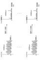
- the feature creation unit 2102 creates features by, for example, performing a Fourier transform on each piece of state data (torque) extracted by the state data extraction unit 2101 in the frequency domain, normalizing the amplitude or power density, and calculating statistics (average, variance, etc.), as shown in FIG. 4 .
- the feature model operation unit 211 generates, updates, deletes, and adds feature models stored in the feature model storage unit 216 described later, based on the context in production operation input from the context acquisition unit 111 and the feature amount indicating the feature of the operation state of the machine tool 30 created by the feature amount creation unit 2102.
- the feature model operation unit 211 selects a feature model to be generated, updated, deleted, or added based on the context in production operation input from the context acquisition unit 111, and performs machine learning on the selected feature model using the feature amount indicating the feature of the state of production operation created by the feature amount creation unit 2102.
- the feature model operation unit 211 newly generates a tentative reference (feature model) associated with the context (combination of contexts) from the frequency distribution of micro-vibrations of 50 state data shown in FIG.
- the feature model operation unit 211 may store a feature model associated with the context (combination) of the production operation input from the context acquisition unit 111 in the feature model memory unit 216, and when the state of a feature indicating a characteristic of the state of the production operation created by the feature creation unit 2102 is closer to the range of the feature model than a predetermined distance, perform machine learning on the feature model including the feature created by the feature creation unit 2102, and update the feature model.
- the feature model operation unit 211 may perform machine learning using the feature of state B including the feature created by the feature creation unit 2102, to generate and add a new feature model B.
- the feature model operation unit 211 may execute machine learning using the feature amount in the range of the feature models A and B and the feature amount of the state C including the feature amount created by the feature amount creation unit 2102 to generate a new feature model A′.
- the feature model operation unit 211 may delete the feature models A and B from the feature model storage unit 216, update the feature models to the newly generated feature model A′, and store the feature model in the feature model storage unit 216.
- the machine learning in the feature model operation unit 211 may use a variational autoencoder (VAE), a generative adversarial network (GAN), or the like. Any method may be used as long as the inference calculation unit 212 described later can calculate an evaluation value of the driving state.
- VAE variational autoencoder
- GAN generative adversarial network
- the inference calculation unit 212 calculates an evaluation value of the operating state of the machine tool 30 executed by the numerical control unit 110 (and the machine tool 30) based on the feature model selected from the feature model memory unit 216 based on the context of the production operation of the machine tool 30 input from the context acquisition unit 111, and the feature created by the feature creation unit 2102. Specifically, the inference calculation unit 212 inputs a new feature quantity indicating the feature of the state of production operation created by the feature quantity creation unit 2102 to a feature model (provisional reference) selected based on the context of production operation of the machine tool 30 input from the context acquisition unit 111, and calculates an evaluation value (degree of data abnormality) indicating how similar the new feature quantity is to the feature model (provisional reference).
- the evaluation value as a result of calculation (inference) by the inference calculation unit 212 may indicate, for example, a normal/abnormal classification of the operation state of the machine tool 30, information indicating an abnormal part of the operation state of the machine tool 30 (such as a bearing abnormality of the motor 31 or damage to the connection between the motor 31 and the mechanism unit 32), a distance between the current operation state of the machine tool 30 and the distribution of the operation state of the machine tool 30 under normal conditions, etc.
- the inference calculation unit 212 stores the calculated evaluation value in a storage unit not shown.
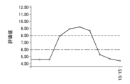
- the fluctuation pattern management unit 213 stores and manages predetermined fluctuation patterns of the evaluation value. Specifically, the fluctuation pattern management unit 213 prestores and manages, for example, the four fluctuation patterns of the evaluation value shown in Figures 7A to 7D. In Figures 7A to 7D, the vertical axis indicates the evaluation value, and the horizontal axis indicates the date.
- the fluctuation pattern of the evaluation value in Fig. 7A is a fluctuation pattern in which the evaluation value rises and then settles back to its original value, and is also referred to as a "back and forth type.” When the evaluation value shows this fluctuation pattern, the evaluation value has returned to its original state, and so feature amount abnormality determination unit 215, described below, determines that machine tool 30 is normal.
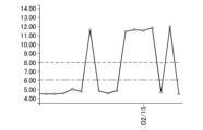
- the fluctuation pattern of the evaluation value in Fig. 7B is a fluctuation pattern in which the evaluation value repeatedly goes up and down and is also called a "spitgle type.”
- the evaluation value shows this fluctuation pattern, the evaluation value goes back and forth between two states (i.e., a state in which the evaluation value is low and a state in which the evaluation value is high), so that the characteristic amount abnormality determination unit 215 described later determines that the machine tool 30 is abnormal.
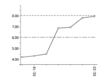
- the fluctuation pattern of the evaluation value in Fig. 7D is a fluctuation pattern in which the evaluation value continues to rise, and is also called an "upward type.”
- the fluctuation pattern management unit 213 stores four fluctuation patterns, it may store three, five, etc. fluctuation patterns.
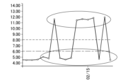
- the fluctuation pattern classification unit 214 classifies the fluctuation pattern of the evaluation value of the operating state of the machine tool 30 based on the calculation results of the inference calculation unit 212 and the predetermined fluctuation patterns stored in the fluctuation pattern management unit 213. Specifically, the fluctuation pattern classification unit 214 reads out, for example, evaluation values for days 3 to 10 as the calculation results of the inference calculation unit 212 from a storage unit (not shown).
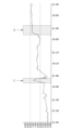
- FIG. 8 is a diagram showing an example of time-series data of the evaluation value calculated by the inference calculation unit 212. As shown in FIG.
- the fluctuation pattern classification unit 214 matches the fluctuation pattern of the evaluation value in the period (1) with the fluctuation patterns of Figures 7A to 7D stored by the fluctuation pattern management unit 213, and classifies it as a "back and forth type".
- the fluctuation pattern classification unit 214 matches the fluctuation pattern of the evaluation value in the period (2) with the fluctuation patterns of Figures 7A to 7D stored by the fluctuation pattern management unit 213, and classifies it as an "upward pause type”.
- the fluctuation pattern classification unit 214 outputs the classification result to the feature amount abnormality determination unit 215.
- the feature amount abnormality determination unit 215 determines whether or not the feature amount of the machine tool 30 is abnormal based on the classification result of the variation pattern classification unit 214. Specifically, for example, when the fluctuation pattern of the evaluation value is the "back and forth type" in Fig. 7A, the feature amount abnormality determination unit 215 determines that the feature amount of the machine tool 30 is normal from the risk evaluation linked to the fluctuation pattern because the original state has been restored. Also, when the fluctuation pattern of the evaluation value is the "spitgle type" in Fig. 7B, the feature amount abnormality determination unit 215 determines that the feature amount of the machine tool 30 is abnormal from the risk evaluation linked to the fluctuation pattern because the evaluation value goes back and forth between two states.
- the feature amount abnormality determination unit 215 considers that a transition has been made to a new state, and determines that the feature amount of the machine tool 30 is abnormal from the risk evaluation linked to the fluctuation pattern. Also, when the fluctuation pattern of the evaluation value is the "rising type” in Fig. 7D, the state continues to change, and determines that the feature amount of the machine tool 30 is abnormal from the risk evaluation linked to the fluctuation pattern.
- the characteristic amount anomaly determination unit 215 may display to the equipment manager on the display 130 of the numerical control device 10 and/or the display 230 of the anomaly detection device 20 that the machine tool 30 needs to be inspected. The equipment manager then inspects the machine tool 30 based on the displayed need for inspection. In this way, preventive maintenance can be performed.
- the feature model storage unit 216 is, for example, a solid state drive (SSD) or a hard disk drive (HDD), and stores a plurality of feature models associated with combinations of contexts in production operations input from the context acquisition unit 111.
- the feature model storage unit 216 may be provided in an external numerical control device 10, a cell computer, a fog computer, a cloud server, a database server, or the like.
- the feature model storage unit 216 stores a plurality of feature models 1, 2, ..., n associated with combinations of contexts (machining status, operating status, environmental status, etc.) in production operation specified by the context acquisition unit 111.
- the combination of contexts in processing operation means combinations related to values, value ranges, and value enumerations that each context can take, and for example, in the case of a combination of a spindle speed, a feed rate, a cutting signal, a tool type, and workpiece information, the combination of contexts can be "spindle speed: 500 to 1000 [rpm], feed rate: 200 to 300 [mm/min], cutting, drill tool, aluminum/steel".
- the feature models stored in the feature model storage unit 216 are created by the feature model operation unit 211 and stored as information capable of configuring one feature model suitable for the inference processing in the inference calculation unit 212.
- the feature models stored in the feature model storage unit 216 may be ones that use a learning algorithm such as a VAE or GAN, which is a multilayer neural network, or may be ones that use a learning algorithm of a Bayesian network.
- each of the feature models stored in the feature model storage unit 216 may be feature models that use the same learning algorithm, or may be feature models that use different learning algorithms, and may be feature models that use any learning algorithm as long as they are usable for the inference processing by the inference calculation unit 212.
- the feature model storage unit 216 may store one feature model in association with a context combination in one production operation, or may store two or more feature models in association with the context combination in one production operation.
- the feature model storage unit 216 may store a plurality of feature models using the same learning algorithm in association with a context combination in one production operation, or may store feature models using two or more different learning algorithms in association with the context combination in one production operation.
- the feature model storage unit 216 may store feature models using different learning algorithms in association with each of the context combinations in a plurality of production operations whose combination ranges overlap. In this case, the feature model storage unit 216 may further store usage conditions such as a required processing capacity and a type of learning algorithm for the feature model corresponding to the context combination in the production operation.
- the inference calculation unit 212 may select a feature model according to an executable inference process or processing capacity for the context combination in the production operation.
- the feature model storage unit 216 may encrypt and store the feature model generated by the feature model operation unit 211, and decrypt the encrypted feature model when the feature model is read out by the inference calculation unit 212.
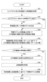
- FIG. 9 is a flowchart illustrating the abnormality detection process of the abnormality detection device 20. The flow shown here is executed every time the numerical control device 10 executes a production operation on the machine tool 30.
- step S11 the feature acquisition unit 210 acquires the context of the production operation of the machine tool 30 and state quantities related to the production operation state of the machine tool 30, and acquires feature quantities related to the production operation state of the machine tool 30 based on the acquired context and state quantities.
- step S12 the inference calculation unit 212 determines whether or not a feature model corresponding to the context in the production operation of the machine tool 30 is stored in the feature model storage unit 216. If a feature model corresponding to the context in the production operation of the machine tool 30 is stored in the feature model storage unit 216, processing proceeds to step S14. On the other hand, if a feature model corresponding to the context in the production operation of the machine tool 30 is not stored in the feature model storage unit 216, processing proceeds to step S13.
- step S13 the feature model operation unit 211 generates a new feature model for the context in production operation acquired in step S11 based on the context and the feature quantity indicating the characteristics of the operating state of the machine tool 30.
- the feature model operation unit 211 stores the generated feature model in the feature model storage unit 216.
- step S14 the inference calculation unit 212 infers (calculates) an evaluation value of the operating state of the machine tool 30 executed by the numerical control unit 110 (and the machine tool 30) based on the feature model selected from the feature model storage unit 216 and the feature amount acquired in step S11.
- step S15 the fluctuation pattern classification unit 214 classifies the fluctuation pattern of the evaluation value of the operating state of the machine tool 30 based on the inference result of step S14 and the predetermined fluctuation pattern stored in the fluctuation pattern management unit 213.
- step S16 the feature abnormality determination unit 215 determines whether the feature of the machine tool 30 is abnormal or not based on the classification result of step S15. If it is determined that the feature of the machine tool 30 is abnormal, the process proceeds to step S17. On the other hand, if it is determined that the feature of the machine tool 30 is normal, the abnormality detection device 20 ends the abnormality detection process.
- step S17 the feature abnormality determination unit 215 outputs the need for inspection of the machine tool 30.
- abnormality detection device 20 can detect abnormalities to present the minimum necessary inspection timing by capturing collective data on changes in the state of machine tool 30, rather than the data for each point of machine tool 30. In other words, abnormality detection device 20 determines whether the risk of machine failure is high or low based on the fluctuation pattern, and detects it as an abnormality when it determines that the risk is high, and prompts inspection of machine tool 30. Furthermore, the anomaly detection device 20 can ignore transient changes that would be deemed abnormal when judged using a threshold value, thereby reducing unnecessary inspections. Furthermore, the anomaly detection device 20 can perform risk assessment by checking the fluctuation pattern when there is a change in the evaluation value. The first embodiment has been described above.
- the abnormality detection device 20 judges whether or not the feature value of the operating state of the machine tool 30 is abnormal based on the classification result of the variation pattern of the evaluation value of the operating state of the machine tool 30 executed by the numerical control unit 110 (and the machine tool 30), and outputs the necessity of inspection of the machine tool 30 when the feature value of the machine tool 30 is judged to be abnormal.
- the abnormality detection device 20A judges that the feature value of the machine tool 30 is abnormal, it accepts an input of the inspection result of the machine tool 30 from a maintenance management record or a facility manager with respect to the necessity of inspection of the machine tool 30 output, and updates the feature model based on the judgment result and the inspection result, which is different from the first embodiment.
- the anomaly detection device 20A according to the second embodiment can detect anomalies to present the minimum necessary inspection timing by capturing data on changes in the state of the industrial machinery collectively, rather than the data on each individual point of the industrial machinery.
- the anomaly detection device 20A can prevent the same anomaly from being detected multiple times, further reducing the number of inspections.
- Fig. 10 is a schematic functional block diagram of an anomaly detection device 20A according to the second embodiment connected to a numerical control device 10. Elements having the same functions as those of the anomaly detection device 20 in Fig. 2 are denoted by the same reference numerals, and detailed description thereof will be omitted.
- an abnormality detection device 20 ⁇ /b>A according to the second embodiment is connected to a numerical control device 10 .
- the numerical control device 10 has the same functions as the numerical control device 10 in the first embodiment.
- the numerical control unit 110, the context acquisition unit 111, and the state quantity acquisition unit 112 have the same functions as the numerical control unit 110, the context acquisition unit 111, and the state quantity acquisition unit 112 in the first embodiment.
- the abnormality detection device 20A includes a feature amount acquisition unit 210, a feature model operation unit 211a, an inference calculation unit 212, a variation pattern management unit 213, a variation pattern classification unit 214, a feature amount abnormality determination unit 215, a feature model storage unit 216, and a machine inspection result holding unit 217.
- the feature amount acquisition unit 210 includes a state data extraction unit 2101, and a feature amount creation unit 2102.
- the feature acquisition unit 210, the inference calculation unit 212, the variation pattern management unit 213, the variation pattern classification unit 214, the feature abnormality judgment unit 215, and the feature model memory unit 216 have functions similar to those of the feature acquisition unit 210, the inference calculation unit 212, the variation pattern management unit 213, the variation pattern classification unit 214, the feature abnormality judgment unit 215, and the feature model memory unit 216 in the first embodiment.
- the state data extraction unit 2101 and the feature creation unit 2102 have the same functions as the state data extraction unit 2101 and the feature creation unit 2102 in the first embodiment.
- the machine inspection result storage unit 217 acquires inspection information, for example, from a system that manages external inspection records.
- the machine inspection result storage unit 217 may also be an input device, such as a keyboard or touch panel (not shown).
- the feature abnormality determination unit 215 judges that the feature of the machine tool 30 is abnormal and outputs the need for inspection of the machine tool 30
- the machine inspection result storage unit 217 acquires inspection information on the results of a timely inspection of the machine tool 30 from a system that manages external inspection records.
- the machine inspection result storage unit 217 may also accept input of the inspection results from the equipment manager.
- the machine inspection result storage unit 217 outputs the accepted inspection results to the feature model operation unit 211a.
- the feature model operation unit 211a Similar to the feature model operation unit 211 of the first embodiment, the feature model operation unit 211a generates, updates, deletes, and adds feature models stored in the feature model memory unit 216 based on the context in production operation input from the context acquisition unit 111 and feature quantities indicating the characteristics of the operating state of the machine tool 30 created by the feature quantity creation unit 2102. In addition, the feature model operation unit 211 a updates the feature model stored in the feature model memory unit 216 based on the judgment results of the feature amount abnormality judgment unit 215 and the inspection results of the machine inspection result storage unit 217 .
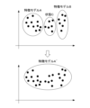
- the feature model operation unit 211a performs machine learning including the feature determined to be normal by the inspection result, and updates the feature model of the context (combination) in production operation input from the context acquisition unit 111. Furthermore, when the fluctuation pattern classification unit 214 determines that the pattern is a "spidgle type," the feature model operation unit 211a may execute machine learning using a feature amount including the two states enclosed in circles as shown in Fig. 11A, to generate and add a new feature model m.
- the feature model operation unit 211a may execute machine learning using a feature amount including the states enclosed in circles as shown in Fig. 11B, to generate and add a new feature model m.
- the feature model operation unit 211a may refrain from updating the feature model until the increase subsides.
- FIG. 12 is a flowchart illustrating the abnormality detection process of the abnormality detection device 20A.
- the processes in steps S21 to S27 are similar to those in steps S11 to S17 in FIG. 9, and therefore will not be described.
- step S28 the machine inspection result storage unit 217 acquires the inspection results of the machine tool 30 in a timely manner in response to the need for inspection output in step S27 from an external system that manages inspection records.
- the machine inspection result storage unit 217 may also accept input of the inspection results from the equipment manager.
- step S29 the feature model operation unit 211a updates the feature model based on the judgment result in step S26 and the inspection result in step S28.
- the anomaly detection device 20A is able to detect anomalies to present the minimum necessary inspection timing by capturing data on changes in the state of the industrial machinery collectively, rather than the data on each individual point of the industrial machinery.
- the anomaly detection device 20A determines whether the risk of a machine failure is high or low based on the fluctuation pattern, and when it determines that the risk is high, detects it as an anomaly and prompts the inspection of the machine tool 30.
- the abnormality detection device 20A can ignore transient changes that would be deemed abnormal when judged using a threshold value, thereby reducing unnecessary inspections.
- the abnormality detection device 20A can perform a risk assessment by checking the fluctuation pattern.
- the anomaly detection device 20A automatically determines whether to update the feature model based on the fluctuation pattern, there is no need to adjust the threshold value, and this makes it possible to avoid the problem of not knowing the appropriate threshold value in the first place.
- the second embodiment has been described above.
- the anomaly detection devices 20 and 20A can detect anomalies to present the minimum necessary inspection timing by capturing collective data on changes in the condition of industrial machinery, rather than the data on each individual point of the industrial machinery.
- the anomaly detection devices 20, 20A are illustrated as devices different from the numerical control device 10, but the numerical control device 10 may be provided with some or all of the functions of the anomaly detection devices 20, 20A.
- a server may be provided with, for example, a part or all of the feature amount acquisition unit 210, the feature model operation unit 211, the inference calculation unit 212, the fluctuation pattern management unit 213, the fluctuation pattern classification unit 214, the feature amount abnormality determination unit 215, and the feature model storage unit 216 of the anomaly detection device 20, or a part or all of the feature amount acquisition unit 210, the feature model operation unit 211a, the inference calculation unit 212, the fluctuation pattern management unit 213, the fluctuation pattern classification unit 214, the feature amount abnormality determination unit 215, the feature model storage unit 216, and the machine inspection result storage unit 217 of the anomaly detection device 20A.
- the functions of the anomaly detection devices 20 and 20A may be realized by using a virtual server function or the like on a cloud. Furthermore, the anomaly detection devices 20, 20A may be configured as a distributed processing system in which the functions of the anomaly detection devices 20, 20A are appropriately distributed to a plurality of servers.
- one numerical control device 10 is connected to one anomaly detection device 20, 20A, but this is not limited to the above.
- one anomaly detection device 20, 20A may be connected to two or more numerical control devices 10.
- an integrated anomaly detection system may have two or more anomaly detection devices 20, 20A, and each anomaly detection device 20, 20A may be connected to one or more numerical control devices 10.
- some or all of the functions of the variation pattern management unit 213 may be shared between the anomaly detection devices 20, 20A. This allows each of the anomaly detection devices 20, 20A to perform anomaly detection using the same criteria.
- anomaly detection devices 20, 20A determine whether or not the feature amount of machine tool 30 is abnormal from the classification result based on the comparison between the inference result and the predetermined fluctuation pattern stored in fluctuation pattern management unit 213, but this is not limited to the above.
- anomaly detection devices 20, 20A may store past fluctuation patterns in a storage unit (not shown) and perform risk assessment by comparing the classification result with the past fluctuation patterns.
- the anomaly detection devices 20, 20A may notify the equipment manager of the need for inspection when a fluctuation occurs, prompting the manager to carry out the inspection, and then review the fluctuation pattern several days later to evaluate the inspection results and risks.
- each function included in the anomaly detection device 20, 20A in the first and second embodiments can be realized by hardware, software, or a combination of these.
- being realized by software means being realized by a computer reading and executing a program.
- Non-transitory computer readable media include various types of tangible storage media. Examples of non-transitory computer readable media include magnetic recording media (e.g., flexible disks, magnetic tapes, hard disk drives), magneto-optical recording media (e.g., magneto-optical disks), CD-ROMs (Read Only Memory), CD-Rs, CD-R/Ws, and semiconductor memories (e.g., mask ROMs, PROMs (Programmable ROMs), EPROMs (Erasable PROMs), flash ROMs, RAMs).
- the program may also be provided to the computer by various types of temporary computer readable media. Examples of temporary computer readable media include electrical signals, optical signals, and electromagnetic waves.
- the temporary computer readable medium can provide the program to the computer via a wired communication path such as an electric wire or optical fiber, or via a wireless communication path.
- the step of writing the program to be recorded on the recording medium includes not only processes that are performed chronologically according to the order, but also processes that are not necessarily performed chronologically but are executed in parallel or individually.
- the step of writing the program may also be performed by cloud computing.
- the anomaly detection device (20) includes a feature quantity acquisition unit (210) that acquires a context in the production operation of the industrial machine (30) and a state quantity related to the production operation state of the industrial machine (30), and acquires feature quantities related to the production operation state of the industrial machine (30) based on the acquired context and state quantity, a feature model operation unit (211) that generates, updates, deletes, and adds a feature model based on the context and the feature quantity, a feature model storage unit (216) that stores the feature model generated by the feature model operation unit (211), and
- the industrial machine includes an inference calculation unit (212) that calculates an evaluation value of the operating state of the industrial machine (30), a fluctuation pattern management unit (213) that stores and manages a predetermined fluctuation pattern of the evaluation value, a fluctuation pattern classification unit (214) that classifies the fluctuation pattern of the evaluation value of the operating state of the industrial machine (30) based on the calculation result of the in
- the fluctuation pattern classification unit (214) classifies the evaluation value calculated by the inference calculation unit (212) into a fluctuation pattern in which the evaluation value at least continues to rise, a fluctuation pattern in which the evaluation value rises and remains high, a fluctuation pattern in which the evaluation value rises and then settles back to the original value, and a fluctuation pattern in which the evaluation value rises and then settles back to the original value.
- the anomaly detection device (20A) of Supplementary Note 1 or Supplementary Note 2 further includes a machine inspection result storage unit (217) that accepts input of timely inspection results of the industrial machine (30), and the feature model operation unit (211a) updates the feature model stored in the feature model memory unit (216) based on the judgment result of the feature amount anomaly judgment unit (215) and the inspection result of the machine inspection result storage unit (217).
- the fluctuation pattern management unit (213) is shared in part or in whole with the other anomaly detection devices (20, 20A), and the fluctuation pattern detected by the anomaly detection device (20, 20A) is used by the other anomaly detection devices (20, 20A).
- the control device (10) is a control device that controls a motor (31) that drives a mechanism of an industrial machine (30), and is equipped with an abnormality detection device (20, 20A) according to any one of Supplementary Note 1 to Supplementary Note 3.
- the anomaly detection method is an anomaly detection method for operating a computer as an anomaly detection device (20), and includes a feature amount acquisition step of acquiring a context in the production operation of the industrial machine (30) and a state amount related to the production operation state of the industrial machine (30), and acquiring a feature amount related to the production operation state of the industrial machine (30) based on the acquired context and state amount; a feature model operation step of generating, updating, deleting, and adding a feature model based on the context and the feature amount; a feature model storage step of storing the feature model generated in the feature model operation step; an inference calculation step of calculating an evaluation value of the operating state of the industrial machine (30) based on the feature amount and the feature model; a fluctuation pattern management step of storing
- the program causes a computer to realize the following: a feature amount acquisition process for acquiring a context in the production operation of the industrial machine (30) and a state amount related to the production operation state of the industrial machine (30), and acquiring a feature amount related to the production operation state of the industrial machine (30) based on the acquired context and state amount; a feature model operation process for generating, updating, deleting, and adding a feature model based on the context and the feature amount; a feature model storage process for storing the feature model generated in the feature model operation process; an inference calculation process for calculating an evaluation value of the operating state of the industrial machine (30) based on the feature amount and the feature model; a fluctuation pattern management process for storing and managing a predetermined fluctuation pattern of the evaluation value; a fluctuation pattern classification process for classifying the fluctuation pattern of the evaluation value of the operating state of the industrial machine (30) based on the calculation result of the inference calculation process and the predetermined fluctuation pattern stored in the fluctuation pattern management process; and a feature amount abnormality
- the integrated anomaly detection system includes two or more anomaly detection devices (20, 20A) of any one of Supplementary Notes 1 to 3, and the fluctuation pattern management unit (213) is shared in part or in whole between the anomaly detection devices (20, 20A), and the fluctuation pattern detected by one anomaly detection device (20, 20A) is used by the other anomaly detection devices (20, 20A).
- Numerical control device 110 Numerical control unit 111 Context acquisition unit 112 State quantity acquisition unit 20, 20A Abnormality detection device 210 Feature quantity acquisition unit 2101 State data extraction unit 2102 Feature quantity creation unit 211, 211a Feature model operation unit 212 Inference calculation unit 213
- Variation pattern management unit 214 Variation pattern classification unit 215 Feature quantity abnormality determination unit 216 Feature model storage unit 217 Machine inspection result storage unit 30 Machine tool 31 Motor 32 Mechanical unit
Landscapes
- Physics & Mathematics (AREA)
- Engineering & Computer Science (AREA)
- Artificial Intelligence (AREA)
- Evolutionary Computation (AREA)
- Mathematical Physics (AREA)
- General Physics & Mathematics (AREA)
- Automation & Control Theory (AREA)
- Testing And Monitoring For Control Systems (AREA)
- Numerical Control (AREA)
Abstract
Priority Applications (3)
| Application Number | Priority Date | Filing Date | Title |
|---|---|---|---|
| DE112023006459.8T DE112023006459T5 (de) | 2023-08-21 | 2023-08-21 | Anomalienerfassungsvorrichtung, Steuervorrichtung, Anomalienerfassungsverfahren, Programm und integriertes Anomalienerfassungssystem |
| CN202380101532.1A CN121794636A (zh) | 2023-08-21 | 2023-08-21 | 异常检测装置、控制装置、异常检测方法、程序以及综合型异常检测系统 |
| PCT/JP2023/030051 WO2025041238A1 (fr) | 2023-08-21 | 2023-08-21 | Dispositif de détection d'anomalies, dispositif de commande, procédé de détection d'anomalies, programme, et système de détection d'anomalies intégré |
Applications Claiming Priority (1)
| Application Number | Priority Date | Filing Date | Title |
|---|---|---|---|
| PCT/JP2023/030051 WO2025041238A1 (fr) | 2023-08-21 | 2023-08-21 | Dispositif de détection d'anomalies, dispositif de commande, procédé de détection d'anomalies, programme, et système de détection d'anomalies intégré |
Publications (1)
| Publication Number | Publication Date |
|---|---|
| WO2025041238A1 true WO2025041238A1 (fr) | 2025-02-27 |
Family
ID=94731853
Family Applications (1)
| Application Number | Title | Priority Date | Filing Date |
|---|---|---|---|
| PCT/JP2023/030051 Pending WO2025041238A1 (fr) | 2023-08-21 | 2023-08-21 | Dispositif de détection d'anomalies, dispositif de commande, procédé de détection d'anomalies, programme, et système de détection d'anomalies intégré |
Country Status (3)
| Country | Link |
|---|---|
| CN (1) | CN121794636A (fr) |
| DE (1) | DE112023006459T5 (fr) |
| WO (1) | WO2025041238A1 (fr) |
Citations (5)
| Publication number | Priority date | Publication date | Assignee | Title |
|---|---|---|---|---|
| JP2018005855A (ja) * | 2016-07-08 | 2018-01-11 | 株式会社リコー | 診断装置、診断システム、診断方法およびプログラム |
| JP2020107001A (ja) * | 2018-12-26 | 2020-07-09 | 株式会社日立製作所 | 監視モデル更新方法、監視システム、および監視装置 |
| JP2021056880A (ja) * | 2019-09-30 | 2021-04-08 | ファナック株式会社 | 診断装置及び診断方法 |
| JP2022066762A (ja) * | 2020-10-19 | 2022-05-02 | Ihi運搬機械株式会社 | 異常診断装置及び異常診断方法 |
| JP7260069B1 (ja) * | 2022-03-29 | 2023-04-18 | 三菱電機株式会社 | 異常検知装置、機械システム及び異常検知方法 |
Family Cites Families (3)
| Publication number | Priority date | Publication date | Assignee | Title |
|---|---|---|---|---|
| JP7101131B2 (ja) | 2019-01-31 | 2022-07-14 | ファナック株式会社 | 数値制御システム |
| JP7571613B2 (ja) | 2021-02-24 | 2024-10-23 | オムロン株式会社 | 情報処理装置、情報処理プログラムおよび情報処理方法 |
| JP7666203B2 (ja) | 2021-07-30 | 2025-04-22 | オムロン株式会社 | 異常検知装置、異常検知方法、及び異常検知プログラム |
-
2023
- 2023-08-21 CN CN202380101532.1A patent/CN121794636A/zh active Pending
- 2023-08-21 WO PCT/JP2023/030051 patent/WO2025041238A1/fr active Pending
- 2023-08-21 DE DE112023006459.8T patent/DE112023006459T5/de active Pending
Patent Citations (5)
| Publication number | Priority date | Publication date | Assignee | Title |
|---|---|---|---|---|
| JP2018005855A (ja) * | 2016-07-08 | 2018-01-11 | 株式会社リコー | 診断装置、診断システム、診断方法およびプログラム |
| JP2020107001A (ja) * | 2018-12-26 | 2020-07-09 | 株式会社日立製作所 | 監視モデル更新方法、監視システム、および監視装置 |
| JP2021056880A (ja) * | 2019-09-30 | 2021-04-08 | ファナック株式会社 | 診断装置及び診断方法 |
| JP2022066762A (ja) * | 2020-10-19 | 2022-05-02 | Ihi運搬機械株式会社 | 異常診断装置及び異常診断方法 |
| JP7260069B1 (ja) * | 2022-03-29 | 2023-04-18 | 三菱電機株式会社 | 異常検知装置、機械システム及び異常検知方法 |
Also Published As
| Publication number | Publication date |
|---|---|
| DE112023006459T5 (de) | 2026-03-19 |
| CN121794636A (zh) | 2026-04-03 |
Similar Documents
| Publication | Publication Date | Title |
|---|---|---|
| CN107272586B (zh) | 机械学习装置、机械学习方法、故障预知装置及系统 | |
| TWI640390B (zh) | 刀具磨耗監測與預測方法 | |
| US10635081B2 (en) | Tool state estimation apparatus and machine tool | |
| Züfle et al. | A machine learning-based workflow for automatic detection of anomalies in machine tools | |
| Rao | Decision making in the manufacturing environment: using graph theory and fuzzy multiple attribute decision making methods | |
| CN118897507B (zh) | 一种基于实时数据驱动的数字孪生模型搭建方法 | |
| CN111506019B (zh) | 数值控制系统 | |
| CN113678076B (zh) | 用于监控铣削工艺的方法和装置 | |
| CN112987682B (zh) | 控制方法、控制装置和机械设备 | |
| Djuraev et al. | Fractional-order moments method for monitoring and diagnosing electric motor conditions | |
| CN120406373B (zh) | 设备参数协同控制系统及控制方法 | |
| WO2025041238A1 (fr) | Dispositif de détection d'anomalies, dispositif de commande, procédé de détection d'anomalies, programme, et système de détection d'anomalies intégré | |
| JP6781845B2 (ja) | 工作機械の監視システム | |
| CN116113897B (zh) | 用于监测铣床的方法和设备 | |
| CN119809598A (zh) | 基于大数据的机械设备维护监测方法及系统 | |
| CN118647951A (zh) | 诊断装置以及计算机可读取的记录介质 | |
| CN121350935B (zh) | 一种数控镗铣的刀具切削力智能监测方法及系统 | |
| JP2022125608A (ja) | 予測システム、情報処理装置および情報処理プログラム | |
| WO2025052543A1 (fr) | Dispositif de détection d'anomalie et support d'enregistrement lisible par ordinateur | |
| JP7555526B1 (ja) | 学習装置、産業システム、推論装置、学習方法、および推論方法 | |
| CN118861944B (zh) | 一种物联网和虚拟现实技术结合的系统构建方法 | |
| JP7286049B1 (ja) | 学習装置、数値制御装置、加工結果予測方法および加工システム | |
| JP6881700B1 (ja) | 加工レポート作成装置およびワイヤ放電加工機 | |
| Nguyen | Using Machine Learning with Sensor Fusion to Identify Anomalous Toolpaths in Subtractive Manufacturing | |
| WO2023089773A9 (fr) | Dispositif de diagnostic d'anomalie, système de diagnostic d'anomalie et support de stockage |
Legal Events
| Date | Code | Title | Description |
|---|---|---|---|
| 121 | Ep: the epo has been informed by wipo that ep was designated in this application |
Ref document number: 23949699 Country of ref document: EP Kind code of ref document: A1 |
|
| ENP | Entry into the national phase |
Ref document number: 2025541194 Country of ref document: JP Kind code of ref document: A |
|
| WWE | Wipo information: entry into national phase |
Ref document number: 2025541194 Country of ref document: JP |
|
| WWE | Wipo information: entry into national phase |
Ref document number: 112023006459 Country of ref document: DE |
|
| WWP | Wipo information: published in national office |
Ref document number: 112023006459 Country of ref document: DE |