WO2025041238A1 - Abnormality detection device, control device, abnormality detection method, program, and integrated abnormality detection system - Google Patents
Abnormality detection device, control device, abnormality detection method, program, and integrated abnormality detection system Download PDFInfo
- Publication number
- WO2025041238A1 WO2025041238A1 PCT/JP2023/030051 JP2023030051W WO2025041238A1 WO 2025041238 A1 WO2025041238 A1 WO 2025041238A1 JP 2023030051 W JP2023030051 W JP 2023030051W WO 2025041238 A1 WO2025041238 A1 WO 2025041238A1
- Authority
- WO
- WIPO (PCT)
- Prior art keywords
- feature
- unit
- fluctuation pattern
- industrial machine
- feature model
- Prior art date
- Legal status (The legal status is an assumption and is not a legal conclusion. Google has not performed a legal analysis and makes no representation as to the accuracy of the status listed.)
- Pending
Links
Images


Classifications
-
- G—PHYSICS
- G05—CONTROLLING; REGULATING
- G05B—CONTROL OR REGULATING SYSTEMS IN GENERAL; FUNCTIONAL ELEMENTS OF SUCH SYSTEMS; MONITORING OR TESTING ARRANGEMENTS FOR SUCH SYSTEMS OR ELEMENTS
- G05B23/00—Testing or monitoring of control systems or parts thereof
- G05B23/02—Electric testing or monitoring
- G05B23/0205—Electric testing or monitoring by means of a monitoring system capable of detecting and responding to faults
- G05B23/0218—Electric testing or monitoring by means of a monitoring system capable of detecting and responding to faults characterised by the fault detection method dealing with either existing or incipient faults
- G05B23/0224—Process history based detection method, e.g. whereby history implies the availability of large amounts of data
- G05B23/024—Quantitative history assessment, e.g. mathematical relationships between available data; Functions therefor; Principal component analysis [PCA]; Partial least square [PLS]; Statistical classifiers, e.g. Bayesian networks, linear regression or correlation analysis; Neural networks
Definitions
- This disclosure relates to an anomaly detection device, a control device, an anomaly detection method, a program, and an integrated anomaly detection system that detects anomalies in the features of industrial machinery based on the variation patterns of the features.
- measurement data shows that changes in the behavior of industrial machines such as machine tools are not as simple as dividing them into two categories based on a threshold.
- a threshold For example, when changes in evaluation values are viewed over time, they may change in a step-like manner or fluctuate up and down.
- the conventional method of notifying an abnormality when the evaluation value exceeds a predefined threshold results in frequent notifications, which does not lead to meaningful decision-making for the operator. Adjusting the threshold does not fundamentally solve the problem of the difficulty in distinguishing between normal and abnormal.
- the behavior of industrial machinery is unique. Therefore, it is difficult to create and apply general-purpose models and thresholds from large amounts of data in advance. Because the general mechanisms behind failures in industrial machinery such as machine tools have not been fully elucidated, the role required of anomaly detection devices is to match data anomalies with industrial machinery anomalies as closely as possible.
- One aspect of the anomaly detection device disclosed herein includes a feature acquisition unit that acquires a context in the production operation of an industrial machine and a state quantity related to the production operation state of the industrial machine, and acquires feature quantities related to the production operation state of the industrial machine based on the acquired context and the state quantity; a feature model operation unit that generates, updates, deletes, and adds feature models based on the context and the feature quantities; a feature model storage unit that stores the feature models generated by the feature model operation unit; an inference calculation unit that calculates an evaluation value of the operating state of the industrial machine based on the feature quantities and the feature models; a fluctuation pattern management unit that stores and manages a predetermined fluctuation pattern of the evaluation value; a fluctuation pattern classification unit that classifies the fluctuation pattern of the evaluation value of the operating state of the industrial machine based on the calculation result of the inference calculation unit and the predetermined fluctuation pattern stored in the fluctuation pattern management unit; and a feature anomaly determination unit that determines whether the feature quantities of the industrial machine are abnormal based on
- One aspect of the control device disclosed herein is a control device that controls a motor that drives a mechanism of an industrial machine, and is equipped with the anomaly detection device of (1).
- One aspect of the anomaly detection method disclosed herein is an anomaly detection method that causes a computer to operate as an anomaly detection device, and includes a feature acquisition process for acquiring a context in the production operation of an industrial machine and a state quantity related to the production operation state of the industrial machine, and acquiring feature quantities related to the production operation state of the industrial machine based on the acquired context and the state quantity; a feature model operation process for generating, updating, deleting, and adding a feature model based on the context and the feature quantities; a feature model storage process for storing the feature model generated in the feature model operation process; an inference calculation process for calculating an evaluation value of the operating state of the industrial machine based on the feature quantities and the feature model; a fluctuation pattern management process for storing and managing a predetermined fluctuation pattern of the evaluation value; a fluctuation pattern classification process for classifying the fluctuation pattern of the evaluation value of the operating state of the industrial machine based on the calculation result of the inference calculation process and the predetermined fluctuation pattern stored in the fluctuation pattern management process; and
- One aspect of the program disclosed herein is a program that causes a computer to realize a feature acquisition process for acquiring a context in the production operation of an industrial machine and a state quantity related to the production operation state of the industrial machine, and acquiring feature quantities related to the production operation state of the industrial machine based on the acquired context and the state quantity; a feature model operation process for generating, updating, deleting, and adding a feature model based on the context and the feature quantities; a feature model storage process for storing the feature model generated in the feature model operation process; an inference calculation process for calculating an evaluation value of the operating state of the industrial machine based on the feature quantities and the feature model; a fluctuation pattern management process for storing and managing a predetermined fluctuation pattern of the evaluation value; a fluctuation pattern classification process for classifying the fluctuation pattern of the evaluation value of the operating state of the industrial machine based on the calculation result of the inference calculation process and the predetermined fluctuation pattern stored in the fluctuation pattern management process; and a feature abnormality determination process for determining whether or not
- One aspect of the integrated anomaly detection system disclosed herein includes two or more anomaly detection devices according to (1), and the fluctuation pattern management unit is shared in part or in whole between the anomaly detection devices, and the fluctuation pattern detected by one anomaly detection device is used by the other anomaly detection devices.
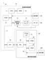
- FIG. 2 is a diagram illustrating an example of a hardware configuration when an anomaly detection device according to the first embodiment is connected to a numerical control device.
- FIG. 1 is a schematic functional block diagram when an anomaly detection device according to a first embodiment is connected to a numerical control device.
- FIG. 13 is a diagram showing an example of time-series data of the speed and torque of a spindle motor to which a tool is attached in a machine tool when not cutting, as a state quantity acquired by a state quantity acquisition unit.
- FIG. 11 is a diagram illustrating an example of the operation of a feature creation unit.
- FIG. 13 is a diagram illustrating an example of a relationship between a feature model and a feature amount.
- FIG. 13 is a diagram illustrating an example of a relationship between a feature model and a feature amount.
- FIG. 13 is a diagram showing an example of a predetermined variation pattern.
- FIG. 13 is a diagram showing an example of a predetermined variation pattern.
- FIG. 13 is a diagram showing an example of a predetermined variation pattern.
- FIG. 13 is a diagram showing an example of a predetermined variation pattern.
- FIG. 11 is a diagram showing an example of time-series data of evaluation values calculated by an inference calculation unit.
- 11 is a flowchart illustrating an abnormality detection process of the abnormality detection device.
- FIG. 11 is a schematic functional block diagram when an anomaly detection device according to a second embodiment is connected to a numerical control device.
- FIG. 11 is a schematic functional block diagram when an anomaly detection device according to a second embodiment is connected to a numerical control device.
- FIG. 13 is a diagram showing an example of how to select data used in machine learning in the case of the “stiffness type.”
- FIG. 13 is a diagram showing an example of how to select data used in machine learning in the case of the “rising pause pattern.”
- 11 is a flowchart illustrating an abnormality detection process of the abnormality detection device.
- FIG. 1 is a diagram illustrating an example of a hardware configuration when an anomaly detection device according to the first embodiment is connected to a numerical control device.
- the abnormality detection device 20 is connected to a numerical control device 10 .
- the numerical control device 10 and the anomaly detection device 20 are directly connected to each other via a connection interface (not shown).
- the numerical control device 10 and the anomaly detection device 20 may be connected to each other and communicate with each other via a network (not shown) such as a local area network (LAN) or the Internet. Furthermore, the numerical control device 10 and the anomaly detection device 20 are described as being different devices, but as will be described later, the anomaly detection device 20 may be included in the numerical control device 10.
- a network not shown
- LAN local area network
- the anomaly detection device 20 may be included in the numerical control device 10.
- the numerical control device 10 is, for example, a numerical control device known to those skilled in the art for controlling the operation of a machine tool (not shown). In addition, if the machine tool (not shown) is a robot or the like, the numerical control device 10 may be a robot control device or the like.
- the numerical control device 10 includes a central processing unit (CPU) 11, a read only memory (ROM) 12, a random access memory (RAM) 13, an axis control circuit 14, a servo amplifier 15, an interface (INT) 16, and a bus 17.
- the numerical control device 10 is also connected to a display 130.
- the CPU 11 is a processor that performs overall control of the numerical control device 10.
- the CPU 11 reads out a system program stored in the ROM 12 via the bus 17, and controls the entire numerical control device 10 in accordance with the system program.
- the RAM 13 temporarily stores temporary calculation data, display data, and various data input by an operator via an input device (not shown), such as a keyboard or a touch panel.
- the axis control circuit 14 receives an axis movement command from the CPU 11 via the bus 17 and outputs the command to the servo amplifier 15.
- the servo amplifier 15 drives a motor 120 that moves an axis of the machine tool (not shown).
- the motor 120 of the axis has a built-in position/speed detector (not shown), and feedbacks position/speed feedback signals from the position/speed detector to the axis control circuit 14 to perform feedback control of the position/speed.
- the INTs 16 and 24 are interfaces for connecting the numerical control device 10 and the abnormality detection device 20 .
- the display 130 is, for example, a liquid crystal display or the like, and is used for operating a machine tool (not shown) that has the numerical control device 10 as a component.
- the display 130 may also display the detection results of an abnormality detection in the machine tool (not shown) by an abnormality detection device 20 (described later).
- the abnormality detection device 20 is, for example, a computer such as a personal computer, a fog computer, or a cloud server, and includes a processor 21, a ROM 22, a RAM 23, an INT 24, and a bus 25.
- the abnormality detection device 20 is also connected to a display 230.
- the processor 21 is, for example, a CPU, which reads out a system program stored in the ROM 22 and controls the entire anomaly detection device 20 in accordance with the system program.
- the RAM 23 temporarily stores temporary calculation data, display data, and various data input by an operator via an input device (not shown) such as a keyboard or a touch panel.
- the INT 24 transmits and receives various data to and from the numerical controller 10 via the INT 16 of the numerical controller 10 .
- the display 230 is a liquid crystal display or the like, and displays the results of processing by the anomaly detection device 20, etc.
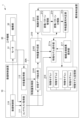
- Fig. 2 is a schematic functional block diagram of an anomaly detection device 20 according to the first embodiment connected to a machine tool 30, which is a type of industrial machine.
- Each functional block shown in Fig. 2 is realized by the CPU 11 of the numerical control device 10 shown in Fig. 1 and the processor 21 of the anomaly detection device 20 controlling the operation of each part of the device according to the respective system programs.
- the numerical control device 10 includes a numerical control unit 110, a context acquisition unit 111, and a state quantity acquisition unit 112.
- the anomaly detection device 20 includes a feature quantity acquisition unit 210, a feature model operation unit 211, an inference calculation unit 212, a variation pattern management unit 213, a variation pattern classification unit 214, a feature quantity anomaly determination unit 215, and a feature model storage unit 216.
- the feature quantity acquisition unit 210 includes a state data extraction unit 2101, and a feature quantity creation unit 2102.
- the numerical control unit 110 controls the machine tool 30 by executing a machining program stored in a memory (not shown).
- the numerical control unit 110 sequentially reads out and analyzes blocks of the machining program stored in a memory (not shown), calculates the movement amount of the motor 31 for each control cycle based on the analysis results, and controls the motor 31 according to the calculated movement amount for each control cycle.
- the machine tool 30 drives a mechanism unit 32 in the machine tool 30, which includes, for example, a ball screw used as a feed axis and a mechanism used as a main axis. In this way, the machine tool 30 machines a workpiece.
- a mechanism unit 32 in the machine tool 30, which includes, for example, a ball screw used as a feed axis and a mechanism used as a main axis. In this way, the machine tool 30 machines a workpiece.
- one motor 31 is connected to one mechanism unit 32 of the machine tool 30, but the number of motors 31 may be the same as the number of axes of the mechanism unit 32 of the
- the context acquisition unit 111 acquires the context (production status, operation status, environmental status, etc.) during production operation performed by the numerical control unit 110 (and the machine tool 30 controlled by the numerical control unit 110), and outputs the acquired context to the abnormality detection device 20.
- the context during production operation includes, for example, the operation pattern of the motor 31 during production operation (spindle speed, feed rate, etc.), the purpose of the currently performed machining (rough machining, finishing machining, etc.), the purpose of the currently performed drive of the moving part (fast forward, cutting feed, etc.), the type of tool used for machining, and work information indicating the hardness and material of the workpiece to be machined.
- the context acquisition unit 111 acquires the context during production operation that is comprehensively determined based on the machining conditions commanded by the machining program, setting information set in the numerical control unit 110 by the operator via an input device (not shown), setting information set in the numerical control unit 110 by another computer connected via a network (not shown), or information detected by devices such as sensors separately provided in the numerical control unit 110, and the values of signals acquired from a PLC (Programmable Logic Controller) (not shown).
- the context acquisition unit 111 outputs the acquired context to the feature acquisition unit 210 and feature model operation unit 211 of the anomaly detection device 20, which will be described later.
- the state quantity acquisition unit 112 acquires state quantities of the production operation state by the numerical control unit 110 (and the machine tool 30 controlled by the numerical control unit 110). Examples of state quantities of the production operation state include the spindle load (current value and torque), the feed axis load (current value and torque), the spindle rotation speed, the feed axis speed, the feed axis position, the position feedback value, the temperature of the motor 31, the vibration value, and sound.
- the state quantity acquisition unit 112 also acquires, as state quantities, for example, the actual waveforms of the rotation speed and torque value of the motor 31 that drives the mechanism unit 32 of the machine tool 30 controlled by the numerical control unit 110.
- the state quantity acquisition unit 112 outputs the acquired state quantities to the feature quantity acquisition unit 210 of the abnormality detection device 20 described later.
- the feature acquisition unit 210 acquires the context of the production operation of the machine tool 30 and state quantities related to the production operation state of the machine tool 30, and acquires feature quantities related to the production operation state of the machine tool 30 based on the acquired context and state quantities.
- the feature acquisition unit 210 includes, for example, a state data extraction unit 2101 and a feature creation unit 2102 .
- the state data extraction unit 2101 extracts state data from the state quantities acquired by the state quantity acquisition unit 112, which is used for inference processing by the inference calculation unit 212 (to be described later) and feature model update processing by the feature model operation unit 211 (to be described later).
- the state data extraction unit 2101 extracts state data from the state quantities acquired by the state quantity acquisition unit 112 using a predetermined extraction pattern based on the context of the production operation input from the context acquisition unit 111, which is used for inference processing and the like.
- the extraction pattern used by the state data extraction unit 2101 is a predetermined data processing method in which parameters are determined based on the context, and may be, for example, data processing such as setting an extraction interval of time-series data obtained based on the context, selecting data, and changing the scale of the state quantities based on the context.
- the extraction pattern used by the state data extraction unit 2101 may be registered in advance in a memory by an operator.
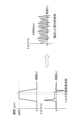
- Fig. 3 is a diagram showing an example of time series data of the speed and torque of a spindle motor to which a tool is attached in machine tool 30 that is not performing machining and is not cutting, as state quantities acquired by state quantity acquisition unit 112.
- the time series data of the speed and torque of the spindle motor is shown on the left side
- the state data of the torque extracted by state data extraction unit 2101 is shown on the right side.
- the time series data of the speed and torque of the spindle motor is data sampled at a sampling frequency of, for example, 0.001 seconds, and is time series data at a predetermined timing when the spindle motor is driven, i.e., when the spindle motor is rotating at a constant speed of about 4000 rpm and running idle.
- the status data extraction unit 2101 extracts, as status data, the torque value in a specific section of the torque time series data, for example, a section (e.g., 0.1 seconds) indicated by a dashed rectangle in which the spindle motor rotates at a constant speed of about 4000 rpm and is idling without any external force acting. As shown on the right side of Fig.
- the torque, which is the extracted status data is not a constant value but indicates minute vibrations as shown on the left side of Fig. 3.
- the status data extraction unit 2101 extracts, as status data, torques indicating minute vibrations as shown on the right side of Fig. 3 from each of the time series data of the speeds and torques of a plurality of spindle motors when the spindle motors rotate at a constant speed (e.g., about 4000 rpm, etc.) and are idling as shown on the left side of Fig. 3.
- the state data extraction unit 2101 outputs the extracted state data to the feature creation unit 2102 .
- the feature quantity creation unit 2102 creates feature quantities indicating characteristics of the operating state of the machine tool 30 controlled by the numerical control unit 110, based on the state data extracted by the state data extraction unit 2101.
- the feature quantities created by the feature quantity creation unit 2102 indicate characteristics of the operating state of the machine tool 30, and are useful information as material for making decisions when detecting an abnormality in the operating state of the machine tool 30 during production operations performed by the numerical control unit 110 (and the machine tool 30).
- the feature quantities created by the feature quantity creation unit 2102 are input data when the inference calculation unit 212, described later, performs inference using a feature model.
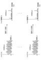
- the feature creation unit 2102 creates features by, for example, performing a Fourier transform on each piece of state data (torque) extracted by the state data extraction unit 2101 in the frequency domain, normalizing the amplitude or power density, and calculating statistics (average, variance, etc.), as shown in FIG. 4 .
- the feature model operation unit 211 generates, updates, deletes, and adds feature models stored in the feature model storage unit 216 described later, based on the context in production operation input from the context acquisition unit 111 and the feature amount indicating the feature of the operation state of the machine tool 30 created by the feature amount creation unit 2102.
- the feature model operation unit 211 selects a feature model to be generated, updated, deleted, or added based on the context in production operation input from the context acquisition unit 111, and performs machine learning on the selected feature model using the feature amount indicating the feature of the state of production operation created by the feature amount creation unit 2102.
- the feature model operation unit 211 newly generates a tentative reference (feature model) associated with the context (combination of contexts) from the frequency distribution of micro-vibrations of 50 state data shown in FIG.
- the feature model operation unit 211 may store a feature model associated with the context (combination) of the production operation input from the context acquisition unit 111 in the feature model memory unit 216, and when the state of a feature indicating a characteristic of the state of the production operation created by the feature creation unit 2102 is closer to the range of the feature model than a predetermined distance, perform machine learning on the feature model including the feature created by the feature creation unit 2102, and update the feature model.
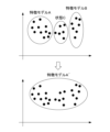
- the feature model operation unit 211 may perform machine learning using the feature of state B including the feature created by the feature creation unit 2102, to generate and add a new feature model B.
- the feature model operation unit 211 may execute machine learning using the feature amount in the range of the feature models A and B and the feature amount of the state C including the feature amount created by the feature amount creation unit 2102 to generate a new feature model A′.
- the feature model operation unit 211 may delete the feature models A and B from the feature model storage unit 216, update the feature models to the newly generated feature model A′, and store the feature model in the feature model storage unit 216.
- the machine learning in the feature model operation unit 211 may use a variational autoencoder (VAE), a generative adversarial network (GAN), or the like. Any method may be used as long as the inference calculation unit 212 described later can calculate an evaluation value of the driving state.
- VAE variational autoencoder
- GAN generative adversarial network
- the inference calculation unit 212 calculates an evaluation value of the operating state of the machine tool 30 executed by the numerical control unit 110 (and the machine tool 30) based on the feature model selected from the feature model memory unit 216 based on the context of the production operation of the machine tool 30 input from the context acquisition unit 111, and the feature created by the feature creation unit 2102. Specifically, the inference calculation unit 212 inputs a new feature quantity indicating the feature of the state of production operation created by the feature quantity creation unit 2102 to a feature model (provisional reference) selected based on the context of production operation of the machine tool 30 input from the context acquisition unit 111, and calculates an evaluation value (degree of data abnormality) indicating how similar the new feature quantity is to the feature model (provisional reference).
- the evaluation value as a result of calculation (inference) by the inference calculation unit 212 may indicate, for example, a normal/abnormal classification of the operation state of the machine tool 30, information indicating an abnormal part of the operation state of the machine tool 30 (such as a bearing abnormality of the motor 31 or damage to the connection between the motor 31 and the mechanism unit 32), a distance between the current operation state of the machine tool 30 and the distribution of the operation state of the machine tool 30 under normal conditions, etc.
- the inference calculation unit 212 stores the calculated evaluation value in a storage unit not shown.
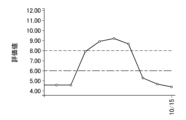
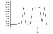
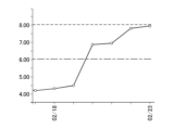
- the fluctuation pattern management unit 213 stores and manages predetermined fluctuation patterns of the evaluation value. Specifically, the fluctuation pattern management unit 213 prestores and manages, for example, the four fluctuation patterns of the evaluation value shown in Figures 7A to 7D. In Figures 7A to 7D, the vertical axis indicates the evaluation value, and the horizontal axis indicates the date.
- the fluctuation pattern of the evaluation value in Fig. 7A is a fluctuation pattern in which the evaluation value rises and then settles back to its original value, and is also referred to as a "back and forth type.” When the evaluation value shows this fluctuation pattern, the evaluation value has returned to its original state, and so feature amount abnormality determination unit 215, described below, determines that machine tool 30 is normal.
- the fluctuation pattern of the evaluation value in Fig. 7B is a fluctuation pattern in which the evaluation value repeatedly goes up and down and is also called a "spitgle type.”
- the evaluation value shows this fluctuation pattern, the evaluation value goes back and forth between two states (i.e., a state in which the evaluation value is low and a state in which the evaluation value is high), so that the characteristic amount abnormality determination unit 215 described later determines that the machine tool 30 is abnormal.
- the fluctuation pattern of the evaluation value in Fig. 7D is a fluctuation pattern in which the evaluation value continues to rise, and is also called an "upward type.”
- the fluctuation pattern management unit 213 stores four fluctuation patterns, it may store three, five, etc. fluctuation patterns.
- the fluctuation pattern classification unit 214 classifies the fluctuation pattern of the evaluation value of the operating state of the machine tool 30 based on the calculation results of the inference calculation unit 212 and the predetermined fluctuation patterns stored in the fluctuation pattern management unit 213. Specifically, the fluctuation pattern classification unit 214 reads out, for example, evaluation values for days 3 to 10 as the calculation results of the inference calculation unit 212 from a storage unit (not shown).
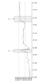
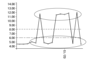
- FIG. 8 is a diagram showing an example of time-series data of the evaluation value calculated by the inference calculation unit 212. As shown in FIG.
- the fluctuation pattern classification unit 214 matches the fluctuation pattern of the evaluation value in the period (1) with the fluctuation patterns of Figures 7A to 7D stored by the fluctuation pattern management unit 213, and classifies it as a "back and forth type".
- the fluctuation pattern classification unit 214 matches the fluctuation pattern of the evaluation value in the period (2) with the fluctuation patterns of Figures 7A to 7D stored by the fluctuation pattern management unit 213, and classifies it as an "upward pause type”.
- the fluctuation pattern classification unit 214 outputs the classification result to the feature amount abnormality determination unit 215.
- the feature amount abnormality determination unit 215 determines whether or not the feature amount of the machine tool 30 is abnormal based on the classification result of the variation pattern classification unit 214. Specifically, for example, when the fluctuation pattern of the evaluation value is the "back and forth type" in Fig. 7A, the feature amount abnormality determination unit 215 determines that the feature amount of the machine tool 30 is normal from the risk evaluation linked to the fluctuation pattern because the original state has been restored. Also, when the fluctuation pattern of the evaluation value is the "spitgle type" in Fig. 7B, the feature amount abnormality determination unit 215 determines that the feature amount of the machine tool 30 is abnormal from the risk evaluation linked to the fluctuation pattern because the evaluation value goes back and forth between two states.
- the feature amount abnormality determination unit 215 considers that a transition has been made to a new state, and determines that the feature amount of the machine tool 30 is abnormal from the risk evaluation linked to the fluctuation pattern. Also, when the fluctuation pattern of the evaluation value is the "rising type” in Fig. 7D, the state continues to change, and determines that the feature amount of the machine tool 30 is abnormal from the risk evaluation linked to the fluctuation pattern.
- the characteristic amount anomaly determination unit 215 may display to the equipment manager on the display 130 of the numerical control device 10 and/or the display 230 of the anomaly detection device 20 that the machine tool 30 needs to be inspected. The equipment manager then inspects the machine tool 30 based on the displayed need for inspection. In this way, preventive maintenance can be performed.
- the feature model storage unit 216 is, for example, a solid state drive (SSD) or a hard disk drive (HDD), and stores a plurality of feature models associated with combinations of contexts in production operations input from the context acquisition unit 111.
- the feature model storage unit 216 may be provided in an external numerical control device 10, a cell computer, a fog computer, a cloud server, a database server, or the like.
- the feature model storage unit 216 stores a plurality of feature models 1, 2, ..., n associated with combinations of contexts (machining status, operating status, environmental status, etc.) in production operation specified by the context acquisition unit 111.
- the combination of contexts in processing operation means combinations related to values, value ranges, and value enumerations that each context can take, and for example, in the case of a combination of a spindle speed, a feed rate, a cutting signal, a tool type, and workpiece information, the combination of contexts can be "spindle speed: 500 to 1000 [rpm], feed rate: 200 to 300 [mm/min], cutting, drill tool, aluminum/steel".
- the feature models stored in the feature model storage unit 216 are created by the feature model operation unit 211 and stored as information capable of configuring one feature model suitable for the inference processing in the inference calculation unit 212.
- the feature models stored in the feature model storage unit 216 may be ones that use a learning algorithm such as a VAE or GAN, which is a multilayer neural network, or may be ones that use a learning algorithm of a Bayesian network.
- each of the feature models stored in the feature model storage unit 216 may be feature models that use the same learning algorithm, or may be feature models that use different learning algorithms, and may be feature models that use any learning algorithm as long as they are usable for the inference processing by the inference calculation unit 212.
- the feature model storage unit 216 may store one feature model in association with a context combination in one production operation, or may store two or more feature models in association with the context combination in one production operation.
- the feature model storage unit 216 may store a plurality of feature models using the same learning algorithm in association with a context combination in one production operation, or may store feature models using two or more different learning algorithms in association with the context combination in one production operation.
- the feature model storage unit 216 may store feature models using different learning algorithms in association with each of the context combinations in a plurality of production operations whose combination ranges overlap. In this case, the feature model storage unit 216 may further store usage conditions such as a required processing capacity and a type of learning algorithm for the feature model corresponding to the context combination in the production operation.
- the inference calculation unit 212 may select a feature model according to an executable inference process or processing capacity for the context combination in the production operation.
- the feature model storage unit 216 may encrypt and store the feature model generated by the feature model operation unit 211, and decrypt the encrypted feature model when the feature model is read out by the inference calculation unit 212.
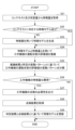
- FIG. 9 is a flowchart illustrating the abnormality detection process of the abnormality detection device 20. The flow shown here is executed every time the numerical control device 10 executes a production operation on the machine tool 30.
- step S11 the feature acquisition unit 210 acquires the context of the production operation of the machine tool 30 and state quantities related to the production operation state of the machine tool 30, and acquires feature quantities related to the production operation state of the machine tool 30 based on the acquired context and state quantities.
- step S12 the inference calculation unit 212 determines whether or not a feature model corresponding to the context in the production operation of the machine tool 30 is stored in the feature model storage unit 216. If a feature model corresponding to the context in the production operation of the machine tool 30 is stored in the feature model storage unit 216, processing proceeds to step S14. On the other hand, if a feature model corresponding to the context in the production operation of the machine tool 30 is not stored in the feature model storage unit 216, processing proceeds to step S13.
- step S13 the feature model operation unit 211 generates a new feature model for the context in production operation acquired in step S11 based on the context and the feature quantity indicating the characteristics of the operating state of the machine tool 30.
- the feature model operation unit 211 stores the generated feature model in the feature model storage unit 216.
- step S14 the inference calculation unit 212 infers (calculates) an evaluation value of the operating state of the machine tool 30 executed by the numerical control unit 110 (and the machine tool 30) based on the feature model selected from the feature model storage unit 216 and the feature amount acquired in step S11.
- step S15 the fluctuation pattern classification unit 214 classifies the fluctuation pattern of the evaluation value of the operating state of the machine tool 30 based on the inference result of step S14 and the predetermined fluctuation pattern stored in the fluctuation pattern management unit 213.
- step S16 the feature abnormality determination unit 215 determines whether the feature of the machine tool 30 is abnormal or not based on the classification result of step S15. If it is determined that the feature of the machine tool 30 is abnormal, the process proceeds to step S17. On the other hand, if it is determined that the feature of the machine tool 30 is normal, the abnormality detection device 20 ends the abnormality detection process.
- step S17 the feature abnormality determination unit 215 outputs the need for inspection of the machine tool 30.
- abnormality detection device 20 can detect abnormalities to present the minimum necessary inspection timing by capturing collective data on changes in the state of machine tool 30, rather than the data for each point of machine tool 30. In other words, abnormality detection device 20 determines whether the risk of machine failure is high or low based on the fluctuation pattern, and detects it as an abnormality when it determines that the risk is high, and prompts inspection of machine tool 30. Furthermore, the anomaly detection device 20 can ignore transient changes that would be deemed abnormal when judged using a threshold value, thereby reducing unnecessary inspections. Furthermore, the anomaly detection device 20 can perform risk assessment by checking the fluctuation pattern when there is a change in the evaluation value. The first embodiment has been described above.
- the abnormality detection device 20 judges whether or not the feature value of the operating state of the machine tool 30 is abnormal based on the classification result of the variation pattern of the evaluation value of the operating state of the machine tool 30 executed by the numerical control unit 110 (and the machine tool 30), and outputs the necessity of inspection of the machine tool 30 when the feature value of the machine tool 30 is judged to be abnormal.
- the abnormality detection device 20A judges that the feature value of the machine tool 30 is abnormal, it accepts an input of the inspection result of the machine tool 30 from a maintenance management record or a facility manager with respect to the necessity of inspection of the machine tool 30 output, and updates the feature model based on the judgment result and the inspection result, which is different from the first embodiment.
- the anomaly detection device 20A according to the second embodiment can detect anomalies to present the minimum necessary inspection timing by capturing data on changes in the state of the industrial machinery collectively, rather than the data on each individual point of the industrial machinery.
- the anomaly detection device 20A can prevent the same anomaly from being detected multiple times, further reducing the number of inspections.
- Fig. 10 is a schematic functional block diagram of an anomaly detection device 20A according to the second embodiment connected to a numerical control device 10. Elements having the same functions as those of the anomaly detection device 20 in Fig. 2 are denoted by the same reference numerals, and detailed description thereof will be omitted.
- an abnormality detection device 20 ⁇ /b>A according to the second embodiment is connected to a numerical control device 10 .
- the numerical control device 10 has the same functions as the numerical control device 10 in the first embodiment.
- the numerical control unit 110, the context acquisition unit 111, and the state quantity acquisition unit 112 have the same functions as the numerical control unit 110, the context acquisition unit 111, and the state quantity acquisition unit 112 in the first embodiment.
- the abnormality detection device 20A includes a feature amount acquisition unit 210, a feature model operation unit 211a, an inference calculation unit 212, a variation pattern management unit 213, a variation pattern classification unit 214, a feature amount abnormality determination unit 215, a feature model storage unit 216, and a machine inspection result holding unit 217.
- the feature amount acquisition unit 210 includes a state data extraction unit 2101, and a feature amount creation unit 2102.
- the feature acquisition unit 210, the inference calculation unit 212, the variation pattern management unit 213, the variation pattern classification unit 214, the feature abnormality judgment unit 215, and the feature model memory unit 216 have functions similar to those of the feature acquisition unit 210, the inference calculation unit 212, the variation pattern management unit 213, the variation pattern classification unit 214, the feature abnormality judgment unit 215, and the feature model memory unit 216 in the first embodiment.
- the state data extraction unit 2101 and the feature creation unit 2102 have the same functions as the state data extraction unit 2101 and the feature creation unit 2102 in the first embodiment.
- the machine inspection result storage unit 217 acquires inspection information, for example, from a system that manages external inspection records.
- the machine inspection result storage unit 217 may also be an input device, such as a keyboard or touch panel (not shown).
- the feature abnormality determination unit 215 judges that the feature of the machine tool 30 is abnormal and outputs the need for inspection of the machine tool 30
- the machine inspection result storage unit 217 acquires inspection information on the results of a timely inspection of the machine tool 30 from a system that manages external inspection records.
- the machine inspection result storage unit 217 may also accept input of the inspection results from the equipment manager.
- the machine inspection result storage unit 217 outputs the accepted inspection results to the feature model operation unit 211a.
- the feature model operation unit 211a Similar to the feature model operation unit 211 of the first embodiment, the feature model operation unit 211a generates, updates, deletes, and adds feature models stored in the feature model memory unit 216 based on the context in production operation input from the context acquisition unit 111 and feature quantities indicating the characteristics of the operating state of the machine tool 30 created by the feature quantity creation unit 2102. In addition, the feature model operation unit 211 a updates the feature model stored in the feature model memory unit 216 based on the judgment results of the feature amount abnormality judgment unit 215 and the inspection results of the machine inspection result storage unit 217 .
- the feature model operation unit 211a performs machine learning including the feature determined to be normal by the inspection result, and updates the feature model of the context (combination) in production operation input from the context acquisition unit 111. Furthermore, when the fluctuation pattern classification unit 214 determines that the pattern is a "spidgle type," the feature model operation unit 211a may execute machine learning using a feature amount including the two states enclosed in circles as shown in Fig. 11A, to generate and add a new feature model m.
- the feature model operation unit 211a may execute machine learning using a feature amount including the states enclosed in circles as shown in Fig. 11B, to generate and add a new feature model m.
- the feature model operation unit 211a may refrain from updating the feature model until the increase subsides.
- FIG. 12 is a flowchart illustrating the abnormality detection process of the abnormality detection device 20A.
- the processes in steps S21 to S27 are similar to those in steps S11 to S17 in FIG. 9, and therefore will not be described.
- step S28 the machine inspection result storage unit 217 acquires the inspection results of the machine tool 30 in a timely manner in response to the need for inspection output in step S27 from an external system that manages inspection records.
- the machine inspection result storage unit 217 may also accept input of the inspection results from the equipment manager.
- step S29 the feature model operation unit 211a updates the feature model based on the judgment result in step S26 and the inspection result in step S28.
- the anomaly detection device 20A is able to detect anomalies to present the minimum necessary inspection timing by capturing data on changes in the state of the industrial machinery collectively, rather than the data on each individual point of the industrial machinery.
- the anomaly detection device 20A determines whether the risk of a machine failure is high or low based on the fluctuation pattern, and when it determines that the risk is high, detects it as an anomaly and prompts the inspection of the machine tool 30.
- the abnormality detection device 20A can ignore transient changes that would be deemed abnormal when judged using a threshold value, thereby reducing unnecessary inspections.
- the abnormality detection device 20A can perform a risk assessment by checking the fluctuation pattern.
- the anomaly detection device 20A automatically determines whether to update the feature model based on the fluctuation pattern, there is no need to adjust the threshold value, and this makes it possible to avoid the problem of not knowing the appropriate threshold value in the first place.
- the second embodiment has been described above.
- the anomaly detection devices 20 and 20A can detect anomalies to present the minimum necessary inspection timing by capturing collective data on changes in the condition of industrial machinery, rather than the data on each individual point of the industrial machinery.
- the anomaly detection devices 20, 20A are illustrated as devices different from the numerical control device 10, but the numerical control device 10 may be provided with some or all of the functions of the anomaly detection devices 20, 20A.
- a server may be provided with, for example, a part or all of the feature amount acquisition unit 210, the feature model operation unit 211, the inference calculation unit 212, the fluctuation pattern management unit 213, the fluctuation pattern classification unit 214, the feature amount abnormality determination unit 215, and the feature model storage unit 216 of the anomaly detection device 20, or a part or all of the feature amount acquisition unit 210, the feature model operation unit 211a, the inference calculation unit 212, the fluctuation pattern management unit 213, the fluctuation pattern classification unit 214, the feature amount abnormality determination unit 215, the feature model storage unit 216, and the machine inspection result storage unit 217 of the anomaly detection device 20A.
- the functions of the anomaly detection devices 20 and 20A may be realized by using a virtual server function or the like on a cloud. Furthermore, the anomaly detection devices 20, 20A may be configured as a distributed processing system in which the functions of the anomaly detection devices 20, 20A are appropriately distributed to a plurality of servers.
- one numerical control device 10 is connected to one anomaly detection device 20, 20A, but this is not limited to the above.
- one anomaly detection device 20, 20A may be connected to two or more numerical control devices 10.
- an integrated anomaly detection system may have two or more anomaly detection devices 20, 20A, and each anomaly detection device 20, 20A may be connected to one or more numerical control devices 10.
- some or all of the functions of the variation pattern management unit 213 may be shared between the anomaly detection devices 20, 20A. This allows each of the anomaly detection devices 20, 20A to perform anomaly detection using the same criteria.
- anomaly detection devices 20, 20A determine whether or not the feature amount of machine tool 30 is abnormal from the classification result based on the comparison between the inference result and the predetermined fluctuation pattern stored in fluctuation pattern management unit 213, but this is not limited to the above.
- anomaly detection devices 20, 20A may store past fluctuation patterns in a storage unit (not shown) and perform risk assessment by comparing the classification result with the past fluctuation patterns.
- the anomaly detection devices 20, 20A may notify the equipment manager of the need for inspection when a fluctuation occurs, prompting the manager to carry out the inspection, and then review the fluctuation pattern several days later to evaluate the inspection results and risks.
- each function included in the anomaly detection device 20, 20A in the first and second embodiments can be realized by hardware, software, or a combination of these.
- being realized by software means being realized by a computer reading and executing a program.
- Non-transitory computer readable media include various types of tangible storage media. Examples of non-transitory computer readable media include magnetic recording media (e.g., flexible disks, magnetic tapes, hard disk drives), magneto-optical recording media (e.g., magneto-optical disks), CD-ROMs (Read Only Memory), CD-Rs, CD-R/Ws, and semiconductor memories (e.g., mask ROMs, PROMs (Programmable ROMs), EPROMs (Erasable PROMs), flash ROMs, RAMs).
- the program may also be provided to the computer by various types of temporary computer readable media. Examples of temporary computer readable media include electrical signals, optical signals, and electromagnetic waves.
- the temporary computer readable medium can provide the program to the computer via a wired communication path such as an electric wire or optical fiber, or via a wireless communication path.
- the step of writing the program to be recorded on the recording medium includes not only processes that are performed chronologically according to the order, but also processes that are not necessarily performed chronologically but are executed in parallel or individually.
- the step of writing the program may also be performed by cloud computing.
- the anomaly detection device (20) includes a feature quantity acquisition unit (210) that acquires a context in the production operation of the industrial machine (30) and a state quantity related to the production operation state of the industrial machine (30), and acquires feature quantities related to the production operation state of the industrial machine (30) based on the acquired context and state quantity, a feature model operation unit (211) that generates, updates, deletes, and adds a feature model based on the context and the feature quantity, a feature model storage unit (216) that stores the feature model generated by the feature model operation unit (211), and
- the industrial machine includes an inference calculation unit (212) that calculates an evaluation value of the operating state of the industrial machine (30), a fluctuation pattern management unit (213) that stores and manages a predetermined fluctuation pattern of the evaluation value, a fluctuation pattern classification unit (214) that classifies the fluctuation pattern of the evaluation value of the operating state of the industrial machine (30) based on the calculation result of the in
- the fluctuation pattern classification unit (214) classifies the evaluation value calculated by the inference calculation unit (212) into a fluctuation pattern in which the evaluation value at least continues to rise, a fluctuation pattern in which the evaluation value rises and remains high, a fluctuation pattern in which the evaluation value rises and then settles back to the original value, and a fluctuation pattern in which the evaluation value rises and then settles back to the original value.
- the anomaly detection device (20A) of Supplementary Note 1 or Supplementary Note 2 further includes a machine inspection result storage unit (217) that accepts input of timely inspection results of the industrial machine (30), and the feature model operation unit (211a) updates the feature model stored in the feature model memory unit (216) based on the judgment result of the feature amount anomaly judgment unit (215) and the inspection result of the machine inspection result storage unit (217).
- the fluctuation pattern management unit (213) is shared in part or in whole with the other anomaly detection devices (20, 20A), and the fluctuation pattern detected by the anomaly detection device (20, 20A) is used by the other anomaly detection devices (20, 20A).
- the control device (10) is a control device that controls a motor (31) that drives a mechanism of an industrial machine (30), and is equipped with an abnormality detection device (20, 20A) according to any one of Supplementary Note 1 to Supplementary Note 3.
- the anomaly detection method is an anomaly detection method for operating a computer as an anomaly detection device (20), and includes a feature amount acquisition step of acquiring a context in the production operation of the industrial machine (30) and a state amount related to the production operation state of the industrial machine (30), and acquiring a feature amount related to the production operation state of the industrial machine (30) based on the acquired context and state amount; a feature model operation step of generating, updating, deleting, and adding a feature model based on the context and the feature amount; a feature model storage step of storing the feature model generated in the feature model operation step; an inference calculation step of calculating an evaluation value of the operating state of the industrial machine (30) based on the feature amount and the feature model; a fluctuation pattern management step of storing
- the program causes a computer to realize the following: a feature amount acquisition process for acquiring a context in the production operation of the industrial machine (30) and a state amount related to the production operation state of the industrial machine (30), and acquiring a feature amount related to the production operation state of the industrial machine (30) based on the acquired context and state amount; a feature model operation process for generating, updating, deleting, and adding a feature model based on the context and the feature amount; a feature model storage process for storing the feature model generated in the feature model operation process; an inference calculation process for calculating an evaluation value of the operating state of the industrial machine (30) based on the feature amount and the feature model; a fluctuation pattern management process for storing and managing a predetermined fluctuation pattern of the evaluation value; a fluctuation pattern classification process for classifying the fluctuation pattern of the evaluation value of the operating state of the industrial machine (30) based on the calculation result of the inference calculation process and the predetermined fluctuation pattern stored in the fluctuation pattern management process; and a feature amount abnormality
- the integrated anomaly detection system includes two or more anomaly detection devices (20, 20A) of any one of Supplementary Notes 1 to 3, and the fluctuation pattern management unit (213) is shared in part or in whole between the anomaly detection devices (20, 20A), and the fluctuation pattern detected by one anomaly detection device (20, 20A) is used by the other anomaly detection devices (20, 20A).
- Numerical control device 110 Numerical control unit 111 Context acquisition unit 112 State quantity acquisition unit 20, 20A Abnormality detection device 210 Feature quantity acquisition unit 2101 State data extraction unit 2102 Feature quantity creation unit 211, 211a Feature model operation unit 212 Inference calculation unit 213
- Variation pattern management unit 214 Variation pattern classification unit 215 Feature quantity abnormality determination unit 216 Feature model storage unit 217 Machine inspection result storage unit 30 Machine tool 31 Motor 32 Mechanical unit
Landscapes
- Physics & Mathematics (AREA)
- Engineering & Computer Science (AREA)
- Artificial Intelligence (AREA)
- Evolutionary Computation (AREA)
- Mathematical Physics (AREA)
- General Physics & Mathematics (AREA)
- Automation & Control Theory (AREA)
- Testing And Monitoring For Control Systems (AREA)
- Numerical Control (AREA)
Abstract
Description
本開示は、特徴量の変動パターンに基づいて産業用機械の特徴量の異常を検知する異常検知装置、制御装置、異常検知方法、プログラム、及び統合型異常検知システムに関する。 This disclosure relates to an anomaly detection device, a control device, an anomaly detection method, a program, and an integrated anomaly detection system that detects anomalies in the features of industrial machinery based on the variation patterns of the features.
工作機械やロボット等の産業用機械の故障は生産現場の稼働率低下の原因となる。稼働率低下や不良ワークの発生を防ぐため、産業用機械に対する予防保全を実施したいというニーズがある。
そこで、予防保全を実現するために運転中の情報(制御信号、電流値、振動値等)を収集し、機械学習により特徴量をモデル化して異常検知を行う手法が提案されている。例えば、特許文献1-3参照。これらの従来技術では閾値を設定し、評価値がその閾値を上回った場合に異常とみなし通知する手法が採用されている。
Breakdowns of industrial machinery such as machine tools and robots cause a decline in the operating rate of production sites. To prevent a decline in operating rate and the generation of defective workpieces, there is a need to carry out preventive maintenance of industrial machinery.
In order to realize preventive maintenance, a method has been proposed in which information during operation (control signals, current values, vibration values, etc.) is collected, and feature values are modeled by machine learning to detect anomalies. For example, see
しかしながら、工作機械等の産業用機械の振る舞いの変化は、閾値で二分できるような単純なものではないことが、計測データからわかっている。例えば、評価値の変化を時系列でみた時に、階段状に変化したり、上下に変動したりすることがある。
そのような状況で、評価値が予め定義した閾値を超えたことを根拠に異常を通知する従来手法では、通知が頻発してしまいオペレータにとって意味のある意思決定につながらない。閾値を調整しても、正常異常の二分が困難であることの根本的な解決にはならない。
また、産業用機械の振る舞いには個別性があることも計測データからわかっている。そのため、大規模なデータから予め汎用的なモデル、閾値を作成しあてはめることは困難である。
工作機械等の産業用機械の故障の一般的なメカニズムは解明されていないため、異常検知装置に求められている役割は、データの異常と産業用機械の異常をできるだけすり合わせていくことである。
However, measurement data shows that changes in the behavior of industrial machines such as machine tools are not as simple as dividing them into two categories based on a threshold. For example, when changes in evaluation values are viewed over time, they may change in a step-like manner or fluctuate up and down.
In such a situation, the conventional method of notifying an abnormality when the evaluation value exceeds a predefined threshold results in frequent notifications, which does not lead to meaningful decision-making for the operator. Adjusting the threshold does not fundamentally solve the problem of the difficulty in distinguishing between normal and abnormal.
In addition, it is known from measurement data that the behavior of industrial machinery is unique. Therefore, it is difficult to create and apply general-purpose models and thresholds from large amounts of data in advance.
Because the general mechanisms behind failures in industrial machinery such as machine tools have not been fully elucidated, the role required of anomaly detection devices is to match data anomalies with industrial machinery anomalies as closely as possible.
そこで、産業用機械の1点1点のデータそのものではなく、産業用機械の状態変化についてデータを集合的にとらえることで、必要最小限の点検タイミングを提示するための異常検知を行うことが望まれている。 Therefore, it is desirable to detect anomalies and suggest the minimum necessary timing for inspections by capturing collective data on changes in the condition of industrial machinery, rather than the data on each individual piece of industrial machinery.
(1)本開示の異常検知装置の一態様は、産業用機械の生産運転におけるコンテキストと前記産業用機械の生産運転状態にかかわる状態量とを取得し、取得した前記コンテキストと前記状態量とに基づいて前記産業用機械の生産運転状態にかかわる特徴量を取得する特徴量取得部と、前記コンテキストと前記特徴量とに基づいて特徴モデルを生成、更新、削除、追加する特徴モデル操作部と、前記特徴モデル操作部で生成された前記特徴モデルを記憶する特徴モデル記憶部と、前記特徴量と前記特徴モデルとに基づいて前記産業用機械の運転状態の評価値を計算する推論計算部と、前記評価値の所定の変動パターンを記憶し管理する変動パターン管理部と、前記推論計算部の計算結果と前記変動パターン管理部が記憶している前記所定の変動パターンとに基づいて、前記産業用機械の運転状態の評価値の変動パターンを分類する変動パターン分類部と、前記変動パターン分類部の分類結果に基づいて前記産業用機械の特徴量が異常か否かを判定する特徴量異常判定部と、を備える。 (1) One aspect of the anomaly detection device disclosed herein includes a feature acquisition unit that acquires a context in the production operation of an industrial machine and a state quantity related to the production operation state of the industrial machine, and acquires feature quantities related to the production operation state of the industrial machine based on the acquired context and the state quantity; a feature model operation unit that generates, updates, deletes, and adds feature models based on the context and the feature quantities; a feature model storage unit that stores the feature models generated by the feature model operation unit; an inference calculation unit that calculates an evaluation value of the operating state of the industrial machine based on the feature quantities and the feature models; a fluctuation pattern management unit that stores and manages a predetermined fluctuation pattern of the evaluation value; a fluctuation pattern classification unit that classifies the fluctuation pattern of the evaluation value of the operating state of the industrial machine based on the calculation result of the inference calculation unit and the predetermined fluctuation pattern stored in the fluctuation pattern management unit; and a feature anomaly determination unit that determines whether the feature quantities of the industrial machine are abnormal based on the classification result of the fluctuation pattern classification unit.
(2)本開示の制御装置の一態様は、産業用機械の機構を駆動するモータを制御する制御装置であって、(1)の異常検知装置を備える。 (2) One aspect of the control device disclosed herein is a control device that controls a motor that drives a mechanism of an industrial machine, and is equipped with the anomaly detection device of (1).
(3)本開示の異常検知方法の一態様は、コンピュータを異常検知装置として動作させる異常検知方法であって、産業用機械の生産運転におけるコンテキストと前記産業用機械の生産運転状態にかかわる状態量とを取得し、取得した前記コンテキストと前記状態量とに基づいて前記産業用機械の生産運転状態にかかわる特徴量を取得する特徴量取得工程と、前記コンテキストと前記特徴量とに基づいて特徴モデルを生成、更新、削除、追加する特徴モデル操作工程と、前記特徴モデル操作工程で生成された前記特徴モデルを記憶する特徴モデル記憶工程と、前記特徴量と前記特徴モデルとに基づいて前記産業用機械の運転状態の評価値を計算する推論計算工程と、前記評価値の所定の変動パターンを記憶し管理する変動パターン管理工程と、前記推論計算工程の計算結果と前記変動パターン管理工程で記憶している前記所定の変動パターンとに基づいて、前記産業用機械の運転状態の評価値の変動パターンを分類する変動パターン分類工程と、前記変動パターン分類工程の分類結果に基づいて前記産業用機械の特徴量が異常か否かを判定する特徴量異常判定工程と、を備える。 (3) One aspect of the anomaly detection method disclosed herein is an anomaly detection method that causes a computer to operate as an anomaly detection device, and includes a feature acquisition process for acquiring a context in the production operation of an industrial machine and a state quantity related to the production operation state of the industrial machine, and acquiring feature quantities related to the production operation state of the industrial machine based on the acquired context and the state quantity; a feature model operation process for generating, updating, deleting, and adding a feature model based on the context and the feature quantities; a feature model storage process for storing the feature model generated in the feature model operation process; an inference calculation process for calculating an evaluation value of the operating state of the industrial machine based on the feature quantities and the feature model; a fluctuation pattern management process for storing and managing a predetermined fluctuation pattern of the evaluation value; a fluctuation pattern classification process for classifying the fluctuation pattern of the evaluation value of the operating state of the industrial machine based on the calculation result of the inference calculation process and the predetermined fluctuation pattern stored in the fluctuation pattern management process; and a feature anomaly determination process for determining whether the feature quantity of the industrial machine is abnormal based on the classification result of the fluctuation pattern classification process.
(4)本開示のプログラムの一態様は、コンピュータに、産業用機械の生産運転におけるコンテキストと前記産業用機械の生産運転状態にかかわる状態量とを取得し、取得した前記コンテキストと前記状態量とに基づいて前記産業用機械の生産運転状態にかかわる特徴量を取得する特徴量取得工程と、前記コンテキストと前記特徴量とに基づいて特徴モデルを生成、更新、削除、追加する特徴モデル操作工程と、前記特徴モデル操作工程で生成された前記特徴モデルを記憶する特徴モデル記憶工程と、前記特徴量と前記特徴モデルとに基づいて前記産業用機械の運転状態の評価値を計算する推論計算工程と、前記評価値の所定の変動パターンを記憶し管理する変動パターン管理工程と、前記推論計算工程の計算結果と前記変動パターン管理工程で記憶している前記所定の変動パターンとに基づいて、前記産業用機械の運転状態の評価値の変動パターンを分類する変動パターン分類工程と、前記変動パターン分類工程の分類結果に基づいて前記産業用機械の特徴量が異常か否かを判定する特徴量異常判定工程と、を実現させるプログラム。 (4) One aspect of the program disclosed herein is a program that causes a computer to realize a feature acquisition process for acquiring a context in the production operation of an industrial machine and a state quantity related to the production operation state of the industrial machine, and acquiring feature quantities related to the production operation state of the industrial machine based on the acquired context and the state quantity; a feature model operation process for generating, updating, deleting, and adding a feature model based on the context and the feature quantities; a feature model storage process for storing the feature model generated in the feature model operation process; an inference calculation process for calculating an evaluation value of the operating state of the industrial machine based on the feature quantities and the feature model; a fluctuation pattern management process for storing and managing a predetermined fluctuation pattern of the evaluation value; a fluctuation pattern classification process for classifying the fluctuation pattern of the evaluation value of the operating state of the industrial machine based on the calculation result of the inference calculation process and the predetermined fluctuation pattern stored in the fluctuation pattern management process; and a feature abnormality determination process for determining whether or not the feature quantity of the industrial machine is abnormal based on the classification result of the fluctuation pattern classification process.
(5)本開示の統合型異常検知システムの一態様は、2以上の(1)の異常検知装置を備え、前記変動パターン管理部は、一部又は全部が前記異常検知装置間で共通化され、一の異常検知装置で検出された変動パターンは、他の異常検知装置で使用される。 (5) One aspect of the integrated anomaly detection system disclosed herein includes two or more anomaly detection devices according to (1), and the fluctuation pattern management unit is shared in part or in whole between the anomaly detection devices, and the fluctuation pattern detected by one anomaly detection device is used by the other anomaly detection devices.
<第1実施形態>
以下、第1実施形態に係る異常検知装置について、図を参照しながら詳細に説明する。ここでは、産業用機械の一種である工作機械を異常検知対象として接続する場合を例示する。なお、本発明は、産業用機械として工作機械、産業用ロボット、サービス用ロボット、鍛圧機械、レーザ加工機、及び射出成形機といった様々な機械に対しても適用可能である。
図1は、第1実施形態に係る異常検知装置と数値制御装置とを接続する場合のハードウェア構成の一例を示す図である。
図1に示すように、異常検知装置20は、数値制御装置10と接続される。
数値制御装置10、及び異常検知装置20は、図示しない接続インタフェースを介して互いに直接接続される。なお、数値制御装置10、及び異常検知装置20は、LAN(Local Area Network)やインターネット等の図示しないネットワークを介して相互に接続されて通信を行うようにしてもよい。
また、数値制御装置10と、異常検知装置20とは、互いに異なる装置としたが、後述するように、異常検知装置20は、数値制御装置10に含まれてもよい。
First Embodiment
The anomaly detection device according to the first embodiment will be described in detail below with reference to the drawings. Here, a case where a machine tool, which is a type of industrial machine, is connected as an abnormality detection target will be illustrated. Note that the present invention can also be applied to various machines such as machine tools, industrial robots, service robots, forging machines, laser processing machines, and injection molding machines as industrial machines.
FIG. 1 is a diagram illustrating an example of a hardware configuration when an anomaly detection device according to the first embodiment is connected to a numerical control device.
As shown in FIG. 1 , the
The
Furthermore, the
数値制御装置10は、例えば、図示しない工作機械の動作を制御する当業者にとって公知の数値制御装置である。なお、図示しない工作機械がロボット等の場合、数値制御装置10は、ロボット制御装置等でもよい。
数値制御装置10は、CPU(Central Processing Unit)11、ROM(Read Only Memory)12、RAM(Random Access Memory)13、軸制御回路14、サーボアンプ15、インタフェース(INT)16、及びバス17を有する。また、数値制御装置10は、表示器130に接続される。
CPU11は、数値制御装置10を全体的に制御するプロセッサである。CPU11は、バス17を介して、ROM12に格納されたシステム・プログラムを読み出し、当該システム・プログラムに従って数値制御装置10全体を制御する。RAM13には一時的な計算データや表示データ、キーボードやタッチパネル等の図示しない入力装置を介してオペレータにより入力された各種データ等が一時的に格納される。
軸制御回路14は、図示しない工作機械が有する軸を制御するために、バス17を介してCPU11から軸の移動指令を受け付け、当該指令をサーボアンプ15に出力する。サーボアンプ15は、指令を受け付けると、図示しない工作機械が有する軸を移動させるモータ120を駆動する。軸のモータ120は図示しない位置・速度検出器を内蔵し、当該位置・速度検出器からの位置・速度フィードバック信号を軸制御回路14にフィードバックし、位置・速度のフィードバック制御を行う。なお、図1のハードウェア構成図では、軸制御回路14、サーボアンプ15、モータ120の組は1つしか示さないが、実際には工作機械(図示しない)に備えられた軸の数の組が用意される。
INT16、24は、数値制御装置10と異常検知装置20とを接続するためのインタフェースである。
表示器130は、例えば、液晶ディスプレイ等であり、数値制御装置10を構成要素に持つ図示しない工作機械の操作に使用する。また、表示器130は、後述する異常検知装置20による図示しない工作機械における異常検知の検知結果等を表示してもよい。
The
The
The
In order to control an axis of a machine tool (not shown), the
The
The display 130 is, for example, a liquid crystal display or the like, and is used for operating a machine tool (not shown) that has the
異常検知装置20は、例えば、パーソナルコンピュータ、フォグコンピュータ、クラウドサーバ等のコンピュータ等であり、プロセッサ21、ROM22、RAM23、INT24、及びバス25を有する。また、異常検知装置20は、表示器230に接続される。
プロセッサ21は、例えば、CPU等であり、ROM22に格納されたシステム・プログラムを読み出し、当該システム・プログラムに従って異常検知装置20全体を制御する。RAM23には一時的な計算データや表示データ、キーボードやタッチパネル等の図示しない入力装置を介してオペレータにより入力された各種データ等が一時的に格納される。
INT24は、数値制御装置10のINT16を介して数値制御装置10との間で各種データの送受信を行なう。
表示器230は、液晶ディスプレイ等であり、異常検知装置20による処理の結果等を表示する。
The
The
The
The
図2は、第1実施形態に係る異常検知装置20が産業用機械の一種である工作機械30と接続する場合の概略的な機能ブロック図である。図2に示す各機能ブロックは、図1に示す数値制御装置10のCPU11や、異常検知装置20のプロセッサ21が、それぞれのシステム・プログラムに従って装置の各部の動作を制御することにより実現される。
具体的には、図2において、例えば、数値制御装置10には、数値制御部110、コンテキスト取得部111、及び状態量取得部112を含んで構成される。また、異常検知装置20には、特徴量取得部210、特徴モデル操作部211、推論計算部212、変動パターン管理部213、変動パターン分類部214、特徴量異常判定部215、及び特徴モデル記憶部216を含んで構成される。また、特徴量取得部210は、状態データ抽出部2101、及び特徴量作成部2102を含んで構成される。
Fig. 2 is a schematic functional block diagram of an
2 , for example, the
数値制御部110は、図示しないメモリに記憶された加工プログラムを実行することにより工作機械30を制御する。数値制御部110は、図示しないメモリに記憶された加工プログラムのブロックを逐次読み出して解析し、解析した結果に基づいて制御周期毎のモータ31の移動量を算出し、算出した制御周期毎の移動量に従ってモータ31を制御する。工作機械30は、モータ31が駆動されることにより、工作機械30における、例えば送り軸として用いられるボールネジや、主軸として用いられる機構を含む機構部32を駆動する。これにより、工作機械30はワークを加工する。なお、図2では、1つのモータ31が工作機械30の1つの機構部32と接続されているが、モータ31は工作機械30の機構部32が備える軸の数だけ設置されてもよい。また、単一の機構部32が複数のモータ31で駆動されてもよい。
The
コンテキスト取得部111、数値制御部110(及び数値制御部110により制御される工作機械30)が実行する生産運転におけるコンテキスト(生産状況、運転状況、環境状況等)を取得し、取得したコンテキストを異常検知装置20に対して出力する。生産運転におけるコンテキストとしては、例えば生産運転時のモータ31の動作パターン(主軸回転数、送り速度等)や、現在行われている加工の目的(荒加工、仕上げ加工等)、現在行われている可動部の駆動目的(早送り、切削送り等)、加工に用いられる工具の種類、加工する対象のワークの硬度や材質等を示すワーク情報等がある。コンテキスト取得部111は、加工プログラムにより指令された加工条件、オペレータが図示しない入力装置を介して数値制御部110に設定した設定情報、図示しないネットワーク等を介して接続された他のコンピュータにより数値制御部110に設定された設定情報、又は、数値制御部110に別途設けられたセンサ等の機器により検出された情報、図示しないPLC(Programmable Logic Controller)から取得される信号の値等に基づいて総合的に判断される生産運転におけるコンテキストを取得する。コンテキスト取得部111は、取得したコンテキストを後述する異常検知装置20の特徴量取得部210、及び特徴モデル操作部211に対して出力する。
The
状態量取得部112は、数値制御部110(及び数値制御部110により制御される工作機械30)による生産運転状態の状態量を取得する。生産運転状態の状態量としては、例えば主軸の負荷(電流値やトルク)、送り軸の負荷(電流値やトルク)、主軸回転数、送り軸速度、送り軸位置、位置フィードバック値、モータ31の温度、振動値、音等が例示される。また、状態量取得部112は、例えば、数値制御部110が制御する工作機械30の機構部32を駆動するモータ31に対する回転数やトルク値の実波形を状態量として取得する。状態量取得部112は、取得した状態量を後述する異常検知装置20の特徴量取得部210に出力する。
The state
特徴量取得部210は、工作機械30の生産運転におけるコンテキストと工作機械30の生産運転状態にかかわる状態量とを取得し、取得したコンテキストと状態量とに基づいて工作機械30の生産運転状態にかかわる特徴量を取得する。
具体的には、特徴量取得部210は、例えば、状態データ抽出部2101、及び特徴量作成部2102を有する。
状態データ抽出部2101は、状態量取得部112により取得された状態量から、後述する推論計算部212による推論処理や、後述する特徴モデル操作部211による特徴モデルの更新処理等に用いられる状態データを抽出する。状態データ抽出部2101は、コンテキスト取得部111から入力した生産運転におけるコンテキストに基づいて所定の抽出パターンより状態量取得部112が取得した状態量から推論処理等に用いられる状態データを抽出する。状態データ抽出部2101が用いる抽出パターンは、コンテキストに基づいてパラメータが決定される所定のデータ加工方法であり、例えばコンテキストに基づいて求められる時系列データの抽出区間の設定やデータの選択、コンテキストに基づく状態量のスケール変更等のデータ加工等であってよい。また、状態データ抽出部2101が用いる抽出パターンは、予めオペレータによりメモリ上に登録されてもよい。
The
Specifically, the
The state
以下では、状態データ抽出部2101による、生産運転におけるコンテキストに基づいた所定の抽出パターンによる状態量からの状態データの抽出について説明する。
図3は、状態量取得部112により取得された状態量として、加工をしていない非切削中の工作機械30における工具を取り付けた主軸モータの速度及びトルクの時系列データの一例を示す図である。図3では、左側に主軸モータの速度及びトルクの時系列データを示し、右側に状態データ抽出部2101により抽出されたトルクの状態データを示す。なお、主軸モータの速度及びトルクの時系列データは、例えば、0.001秒のサンプリング周波数でサンプリングされたデータで、主軸モータを駆動させた所定のタイミング、すなわち主軸モータが約4000rpmの一定速度で回転していて、空転している時の時系列データである。
状態データ抽出部2101は、トルクの時系列データのうち特定区間、例えば主軸モータが約4000rpmの一定速度で回転し外力が働かない空転している、破線の矩形で示す区間(例えば、0.1秒)におけるトルクの値を状態データとして抽出する。図3の右側に示すように、抽出された状態データであるトルクは、図3の左側に示すように一定の値ではなく微小な振動を示す。そして、状態データ抽出部2101は、例えば、図3の左側に示すような主軸モータが一定速度(例えば、約4000rpm等)で回転し空転しているときの複数の主軸モータの速度及びトルクの時系列データそれぞれから、図3の右側に示すような微小振動を示すトルクを状態データとして抽出する。
状態データ抽出部2101は、抽出した状態データを特徴量作成部2102に出力する。
The following describes extraction of state data from state quantities by the state
Fig. 3 is a diagram showing an example of time series data of the speed and torque of a spindle motor to which a tool is attached in
The status
The state
特徴量作成部2102は、状態データ抽出部2101が抽出した状態データに基づいて、数値制御部110が制御する工作機械30の運転状態の特徴を示す特徴量を作成する。特徴量作成部2102が作成する特徴量は、工作機械30の運転状態の特徴を示すものであり、数値制御部110(及び工作機械30)が実行する生産運転において、工作機械30の運転状態の異常を検知する際の判断の材料として有用な情報である。また、特徴量作成部2102が作成する特徴量は、後述する推論計算部212が特徴モデルを用いた推論を行う際の入力データである。
特徴量作成部2102は、例えば、図4に示すように、状態データ抽出部2101により抽出された状態データ(トルク)それぞれに対して周波数領域にフーリエ変換したり、振幅又はパワー密度の規格化したり、統計量(平均、分散等)を計算したりして、特徴量を作成する。
The feature
The
特徴モデル操作部211は、コンテキスト取得部111から入力された生産運転におけるコンテキストと、特徴量作成部2102により作成された工作機械30の運転状態の特徴を示す特徴量とに基づいて、後述する特徴モデル記憶部216に記憶される特徴モデルを生成、更新、削除、追加する。特徴モデル操作部211は、コンテキスト取得部111から入力された生産運転におけるコンテキストに基づいて生成、更新、削除、追加の対象となる特徴モデルを選択し、選択した特徴モデルに対して特徴量作成部2102により作成された生産運転の状態の特徴を示す特徴量による機械学習を行う。特徴モデル操作部211は、例えば、コンテキスト取得部111から入力された生産運転におけるコンテキスト(の組み合わせ)と関連付けられた特徴モデルが特徴モデル記憶部216に記憶されていない場合、例えば、図4に示す50回の状態データの微小振動の周波数分布から当該コンテキスト(の組み合わせ)と関連付けた仮基準(特徴モデル)を新たに生成する。
また、特徴モデル操作部211は、コンテキスト取得部111から入力された生産運転におけるコンテキスト(の組み合わせ)と関連付けられた特徴モデルが特徴モデル記憶部216に記憶され、特徴量作成部2102により作成された生産運転の状態の特徴を示す特徴量の状態が当該特徴モデルの範囲に所定の距離より近い場合、特徴量作成部2102により作成された特徴量を含めて当該特徴モデルに対する機械学習を実行し、当該特徴モデルを更新するようにしてもよい。
また、特徴モデル操作部211は、例えば、図5に示すように、コンテキスト取得部111から入力された生産運転におけるコンテキスト(の組み合わせ)と関連付けられた特徴モデルAが特徴モデル記憶部216に記憶され、特徴量作成部2102により作成された特徴量の状態Bが特徴モデルAの範囲から所定の距離以上離れている場合、特徴量作成部2102により作成された特徴量を含む状態Bの特徴量を用いて機械学習を実行し、新たな特徴モデルBを生成し追加するようにしてもよい。
The feature
In addition, the feature
In addition, for example, as shown in FIG. 5 , when a feature model A associated with a context (combination) in production operation input from the
また、特徴モデル操作部211は、例えば、図6に示すように、コンテキスト取得部111から入力された生産運転におけるコンテキスト(の組み合わせ)と関連付けられた特徴モデルA、Bが特徴モデル記憶部216に記憶され、特徴量作成部2102により作成された特徴量の状態Cが特徴モデルA、Bの範囲の中間にある場合、特徴モデルA、Bの範囲の特徴量と特徴量作成部2102により作成された特徴量を含む状態Cの特徴量とを用いて機械学習を実行し、新たな特徴モデルA´を生成するようにしてもよい。特徴モデル操作部211は、特徴モデルA、Bを特徴モデル記憶部216から削除し、新たに生成した特徴モデルA´に更新して特徴モデル記憶部216に記憶するようにしてもよい。
なお、特徴モデル操作部211における機械学習は、VAE(Variational Autoencoder)や、GAN(Generative Adversarial Networks)等を用いることができる。後述する推論計算部212で、運転状態の評価値を計算できるものであれば、手法は問わない。
6 , for example, when feature models A and B associated with the context (combination) in the production operation input from the
The machine learning in the feature
推論計算部212は、コンテキスト取得部111から入力された工作機械30の生産運転におけるコンテキストに基づいて特徴モデル記憶部216から選択された特徴モデルと、特徴量作成部2102が作成した特徴量とに基づいて、数値制御部110(及び工作機械30)が実行する工作機械30の運転状態の評価値を計算する。
具体的には、推論計算部212は、例えば、コンテキスト取得部111から入力された工作機械30の生産運転におけるコンテキストに基づいて選択された特徴モデル(仮基準)に、特徴量作成部2102により作成された生産運転の状態の特徴を示す新たな特徴量を入力することにより、新たな特徴量が特徴モデル(仮基準)とどれくらい類似するかを示す評価値(データ異常度)を計算する。推論計算部212が計算(推論)した結果としての評価値は、例えば工作機械30の運転状態の正常/異常の分類や、工作機械30の運転状態の異常な箇所(モータ31のベアリング異常、モータ31と機構部32との間の連結部の破損等)を示す情報、現在の工作機械30の運転状態と正常時の工作機械30の運転状態の分布との距離等の状態を示すものであってよい。推論計算部212は、計算した評価値を図示しない記憶部に記憶する。
The
Specifically, the
変動パターン管理部213は、評価値の所定の変動パターンを記憶し管理する。
具体的には、変動パターン管理部213は、例えば、図7Aから図7Dに示す4つの評価値の変動パターンを予め記憶して管理する。なお、図7Aから図7Dでは、縦軸は評価値を示し、横軸は日付を示す。
図7Aの評価値の変動パターンは、評価値が上がった後元の値に落ち着く変動パターンで、「往って来い型」ともいう。評価値がこの変動パターンを示す場合、元の状態に戻っていることから、後述する特徴量異常判定部215は、工作機械30が正常と判定する。なお、評価値「8.00」の破線と評価値「6.00」の一点鎖線は、従来の閾値の一例を示し、閾値が工作機械30の正常/異常とあまり関係しないことを示す。
図7Bの評価値の変動パターンは、評価値が上下を繰り返している変動パターンで、「もみ合い型」ともいう。評価値がこの変動パターンを示す場合、2つの状態(すなわち評価値が低い状態と高い状態と)を行き来していることから、後述する特徴量異常判定部215は、工作機械30が異常と判定する。
図7Cの評価値の変動パターンは、評価値が上がって高止まりしている変動パターンで、「上昇一服型」ともいう。評価値がこの変動パターンを示す場合、新しい状態に移行したと考えられ、後述する特徴量異常判定部215は、工作機械30が異常と判定する。
図7Dの評価値の変動パターンは、評価値が上がり続けている変動パターンで、「上昇型」ともいう。評価値がこの変動パターンを示す場合、状態が変化し続けていることから、後述する特徴量異常判定部215は、工作機械30が異常と判定する。
なお、変動パターン管理部213は、4つの変動パターンを記憶したが、3つや5つ等の変動パターンを記憶してもよい。
The fluctuation
Specifically, the fluctuation
The fluctuation pattern of the evaluation value in Fig. 7A is a fluctuation pattern in which the evaluation value rises and then settles back to its original value, and is also referred to as a "back and forth type." When the evaluation value shows this fluctuation pattern, the evaluation value has returned to its original state, and so feature amount
The fluctuation pattern of the evaluation value in Fig. 7B is a fluctuation pattern in which the evaluation value repeatedly goes up and down and is also called a "struggle type." When the evaluation value shows this fluctuation pattern, the evaluation value goes back and forth between two states (i.e., a state in which the evaluation value is low and a state in which the evaluation value is high), so that the characteristic amount
The fluctuation pattern of the evaluation value in Fig. 7C is a fluctuation pattern in which the evaluation value rises and remains high, and is also called an "upward pause type." When the evaluation value shows this fluctuation pattern, it is considered that a transition has been made to a new state, and the characteristic amount
The fluctuation pattern of the evaluation value in Fig. 7D is a fluctuation pattern in which the evaluation value continues to rise, and is also called an "upward type." When the evaluation value shows this fluctuation pattern, the state continues to change, so that the characteristic amount
Although the fluctuation
変動パターン分類部214は、推論計算部212の計算結果と変動パターン管理部213が記憶している所定の変動パターンとに基づいて、工作機械30の運転状態の評価値の変動パターンを分類する。
具体的には、変動パターン分類部214は、例えば、推論計算部212の計算結果として3日から10日分の評価値を図示しない記憶部から読み出す。
図8は、推論計算部212により計算された評価値の時系列データの一例を示す図である。
具体的には、変動パターン分類部214は、例えば、(1)の期間における評価値の変動パターンについて、変動パターン管理部213が記憶する図7Aから図7Dの変動パターンとマッチングを行い、「往って来い型」と分類する。あるいは、変動パターン分類部214は、(2)の期間における評価値の変動パターンについて、変動パターン管理部213が記憶する図7Aから図7Dの変動パターンとマッチングを行い、「上昇一服型」と分類する。変動パターン分類部214は、分類結果を特徴量異常判定部215に出力する。
The fluctuation
Specifically, the fluctuation
FIG. 8 is a diagram showing an example of time-series data of the evaluation value calculated by the
Specifically, for example, the fluctuation
特徴量異常判定部215は、変動パターン分類部214の分類結果に基づいて工作機械30の特徴量が異常か否かを判定する。
具体的には、特徴量異常判定部215は、例えば、評価値の変動パターンが図7Aの「往って来い型」の場合、元の状態に戻っていることから、変動パターンに紐付いたリスク評価から工作機械30の特徴量が正常と判定する。また、特徴量異常判定部215は、評価値の変動パターンが図7Bの「もみ合い型」の場合、2つの状態を行き来していることから、変動パターンに紐付いたリスク評価から工作機械30の特徴量が異常と判定する。また、特徴量異常判定部215は、評価値の変動パターンが図7Cの「上昇一服型」の場合、新しい状態に移行したと考えられ、変動パターンに紐付いたリスク評価から工作機械30の特徴量が異常と判定する。また、特徴量異常判定部215は、評価値の変動パターンが図7Dの「上昇型」の場合、状態が変化し続けていることから、変動パターンに紐付いたリスク評価から工作機械30の特徴量が異常と判定する。
The feature amount
Specifically, for example, when the fluctuation pattern of the evaluation value is the "back and forth type" in Fig. 7A, the feature amount
特徴量異常判定部215は、工作機械30の特徴量が異常と判定した場合、設備責任者に対して工作機械30の点検が必要な旨を数値制御装置10の表示器130及び/又は異常検知装置20の表示器230に表示するようにしてもよい。そして、設備責任者は、表示された点検の必要性に基づいて工作機械30を点検する。そうすることで、予防保全を行うことができる。
If the characteristic amount
特徴モデル記憶部216は、例えば、SSD(Solid State Drive)やHDD(Hard Disk Drive)等であり、コンテキスト取得部111から入力された生産運転におけるコンテキストの組み合わせに関連付けられた複数の特徴モデルを記憶する。なお、特徴モデル記憶部216は、外部の数値制御装置10やセルコンピュータ、フォグコンピュータ、クラウドサーバ、データベースサーバ等に設けられてもよい。
特徴モデル記憶部216には、コンテキスト取得部111により指定された生産運転におけるコンテキスト(加工状況、運転状況、環境状況等)の組み合わせに関連付けられた複数の特徴モデル1,2,…,nが記憶される。ここで、加工運転におけるコンテキスト(加工状況、運転状況、環境状況等)の組み合わせは、それぞれのコンテキストが取り得る値、値の範囲、値の列挙に関する組み合わせを意味し、例えばコンテキストの組み合わせを主軸回転数、送り速度、切削信号、工具種類、ワーク情報の組み合わせの場合、「主軸回転数:500~1000[rpm],送り速度:200~300[mm/min],切削中、ドリル工具,アルミ/鋼鉄」とすることができる。
The feature
The feature
特徴モデル記憶部216に記憶される特徴モデルは、特徴モデル操作部211によって作成され、推論計算部212における推論処理に適合する1つの特徴モデルを構成可能な情報として記憶される。特徴モデル記憶部216に記憶される特徴モデルは、例えば多層ニューラルネットワークであるVAEやGAN等の学習アルゴリズムを用いたものでもよく、ベイジアンネットワークの学習アルゴリズムを用いたものでもよい。また、特徴モデル記憶部216に記憶される特徴モデルのそれぞれは、同じ学習アルゴリズムを用いた特徴モデルであってもよく、異なる学習アルゴリズムを用いた特徴モデルであってもよく、推論計算部212による推論処理に利用可能であればどのような学習アルゴリズムを用いた特徴モデルであってもよい。
特徴モデル記憶部216は、1つの生産運転におけるコンテキストの組み合わせに対して1つの特徴モデルを関連付けて記憶してもよく、2以上の特徴モデルを関連付けて記憶してもよい。また、特徴モデル記憶部216は、1つの生産運転におけるコンテキストの組み合わせに対して、同一の学習アルゴリズムを用いて特徴モデルを複数関連付けてもよく、2以上の異なる学習アルゴリズムを用いた特徴モデルを関連付けて記憶してもよい。特徴モデル記憶部216は、組み合わせの範囲が重畳する複数の生産運転におけるコンテキストの組み合わせのそれぞれに対して異なる学習アルゴリズムを用いた特徴モデルを関連付けて記憶してもよい。この場合、特徴モデル記憶部216には、生産運転におけるコンテキストの組み合わせに対応する特徴モデルに対して、さらに必要処理能力や学習アルゴリズムの種類等の利用条件が記憶されてもよい。これにより、例えば推論計算部212は、生産運転におけるコンテキストの組み合わせに対して、実行可能な推論処理や処理能力に応じた特徴モデルを選択することができる。
なお、特徴モデル記憶部216は、特徴モデル操作部211が生成した特徴モデルを暗号化して記憶し、推論計算部212により特徴モデルが読み出される際に暗号化された特徴モデルを復号化するようにしてもよい。
The feature models stored in the feature
The feature
In addition, the feature
<異常検知装置20の異常検知処理>
次に、図9を参照しながら、異常検知装置20の異常検知処理の流れを説明する。
図9は、異常検知装置20の異常検知処理について説明するフローチャートである。ここで示すフローは、数値制御装置10が工作機械30に対して生産運転を実行する度に実行される。
<Abnormality detection process of the
Next, the flow of an anomaly detection process by the
9 is a flowchart illustrating the abnormality detection process of the
ステップS11において、特徴量取得部210は、工作機械30の生産運転におけるコンテキストと工作機械30の生産運転状態にかかわる状態量とを取得し、取得したコンテキストと状態量とに基づいて工作機械30の生産運転状態にかかわる特徴量を取得する。
In step S11, the
ステップS12において、推論計算部212は、工作機械30の生産運転におけるコンテキストに対応する特徴モデルが特徴モデル記憶部216にあるか否かを判定する。工作機械30の生産運転におけるコンテキストに対応する特徴モデルが特徴モデル記憶部216にある場合、処理はステップS14に進む。一方、工作機械30の生産運転におけるコンテキストに対応する特徴モデルが特徴モデル記憶部216にない場合、処理はステップS13に進む。
In step S12, the
ステップS13において、特徴モデル操作部211は、ステップS11で取得された生産運転におけるコンテキストと工作機械30の運転状態の特徴を示す特徴量とに基づいて、当該コンテキストの新たな特徴モデルを生成する。特徴モデル操作部211は、生成した特徴モデルを特徴モデル記憶部216に記憶する。
In step S13, the feature
ステップS14において、推論計算部212は、特徴モデル記憶部216から選択された特徴モデルと、ステップS11で取得された特徴量とに基づいて、数値制御部110(及び工作機械30)が実行する工作機械30の運転状態の評価値を推論(計算)する。
In step S14, the
ステップS15において、変動パターン分類部214は、ステップS14の推論結果と変動パターン管理部213が記憶している所定の変動パターンとに基づいて、工作機械30の運転状態の評価値の変動パターンを分類する。
In step S15, the fluctuation
ステップS16において、特徴量異常判定部215は、ステップS15の分類結果に基づいて工作機械30の特徴量が異常か否かを判定する。工作機械30の特徴量が異常と判定した場合、処理はステップS17に進む。一方、工作機械30の特徴量が正常と判定した場合、異常検知装置20は、異常検知処理を終了する。
In step S16, the feature
ステップS17において、特徴量異常判定部215は、工作機械30の点検の必要性を出力する。
In step S17, the feature
以上により、第1実施形態に係る異常検知装置20は、工作機械30の1点1点のデータそのものではなく、工作機械30の状態変化についてデータを集合的にとらえることで、必要最小限の点検タイミングを提示するための異常検知を行うことができる。換言すれば、異常検知装置20は、変動パターンによって機械故障のリスクが高いか低いかを判定し、リスクが高いと判定した場合に異常として検知し、工作機械30の点検を促す。
また、異常検知装置20は、閾値での判定では異常とみなすような一過性の変化を無視できるため、無駄な点検を減らすことができる。
また、異常検知装置20は、評価値に変化があったときに、変動パターンを確認することでリスク評価ができる。
以上、第1実施形態について説明した。
As described above,
Furthermore, the
Furthermore, the
The first embodiment has been described above.
<第2実施形態>
次に、第2実施形態について説明する。第1実施形態では異常検知装置20は、数値制御部110(及び工作機械30)が実行する工作機械30の運転状態の評価値の変動パターンの分類結果に基づいて工作機械30の運転状態の特徴量が異常か否かを判定し、工作機械30の特徴量が異常と判定した場合、工作機械30の点検の必要性を出力した。これに対して、第2実施形態では異常検知装置20Aは工作機械30の特徴量が異常と判定した場合、出力した工作機械30の点検の必要性に対して工作機械30の点検結果を保全管理記録や設備責任者からの入力を受け付け、判定結果と点検結果とに基づいて特徴モデルを更新する点で、第1実施形態と相違する。
これにより、第2実施形態に係る異常検知装置20Aは、産業用機械の1点1点のデータそのものではなく、産業用機械の状態変化についてデータを集合的にとらえることで、必要最小限の点検タイミングを提示するための異常検知を行うことができる。また、異常検知装置20Aは、特徴モデルを更新することで、同一の異常を複数回検知することがなくなり、点検回数をさらに減らすことができる。
以下、第2実施形態について説明する。
Second Embodiment
Next, a second embodiment will be described. In the first embodiment, the
As a result, the
The second embodiment will now be described.
第2実施形態に係る異常検知装置20Aのハードウェア構成は、図1の第1実施形態の場合と同様であり、説明は省略する。
図10は、第2実施形態に係る異常検知装置20Aが数値制御装置10と接続する場合の概略的な機能ブロック図である。なお、図2の異常検知装置20の要素と同様の機能を有する要素については、同じ符号を付し、詳細な説明は省略する。
図10に示すように、第2実施形態に係る異常検知装置20Aは、数値制御装置10と接続される。
数値制御装置10は、第1実施形態における数値制御装置10と同様の機能を有する。
数値制御部110、コンテキスト取得部111、及び状態量取得部112は、第1実施形態における数値制御部110、コンテキスト取得部111、及び状態量取得部112と同様の機能を有する。
The hardware configuration of the
Fig. 10 is a schematic functional block diagram of an
As shown in FIG. 10 , an
The
The
異常検知装置20Aは、特徴量取得部210、特徴モデル操作部211a、推論計算部212、変動パターン管理部213、変動パターン分類部214、特徴量異常判定部215、特徴モデル記憶部216、及び機械点検結果保持部217を含んで構成される。また、特徴量取得部210は、状態データ抽出部2101、及び特徴量作成部2102を含んで構成される。
特徴量取得部210、推論計算部212、変動パターン管理部213、変動パターン分類部214、特徴量異常判定部215、及び特徴モデル記憶部216は、第1実施形態における特徴量取得部210、推論計算部212、変動パターン管理部213、変動パターン分類部214、特徴量異常判定部215、及び特徴モデル記憶部216と同様の機能を有する。
状態データ抽出部2101、及び特徴量作成部2102は、第1実施形態における状態データ抽出部2101、及び特徴量作成部2102と同様の機能を有する。
The
The
The state
機械点検結果保持部217は、例えば、外部の点検記録を管理するシステムから点検情報を取得する。また、機械点検結果保持部217は、例えば、図示しないキーボードやタッチパネル等の入力装置であってもよい。機械点検結果保持部217は、特徴量異常判定部215により工作機械30の特徴量が異常と判定され、工作機械30の点検の必要性が出力されたことにより、適時の工作機械30の点検の結果を外部の点検記録を管理するシステムから点検情報を取得する。また、機械点検結果保持部217は、点検結果の入力を設備責任者から受け付けてもよい。機械点検結果保持部217は、受け付けた点検結果を、特徴モデル操作部211aに出力する。
The machine inspection
特徴モデル操作部211aは、第1実施形態の特徴モデル操作部211と同様に、コンテキスト取得部111から入力された生産運転におけるコンテキストと、特徴量作成部2102により作成された工作機械30の運転状態の特徴を示す特徴量とに基づいて、特徴モデル記憶部216に記憶される特徴モデルを生成、更新、削除、追加する。
また、特徴モデル操作部211aは、特徴量異常判定部215の判定結果と機械点検結果保持部217の点検結果とに基づいて、特徴モデル記憶部216に記憶された特徴モデルを更新する。
具体的には、例えば、特徴量異常判定部215が工作機械30の特徴量を異常と判定し、機械点検結果保持部217により工作機械30が正常とする点検結果を受け付けた場合、特徴モデル操作部211aは、点検結果により正常と判定された特徴量を含めた機械学習を実行し、コンテキスト取得部111から入力された生産運転におけるコンテキスト(の組み合わせ)の特徴モデルを更新する。
また、特徴モデル操作部211aは、変動パターン分類部214により「もみ合い型」と判定された場合、図11Aに示すように、円形で囲った2つの状態を含む特徴量を使用して機械学習を実行し、新たな特徴モデルmを生成し追加するようにしてもよい。また、特徴モデル操作部211aは、変動パターン分類部214により「上昇一服型」と判定された場合、図11Bに示すように、円形で囲った状態を含む特徴量を使用して機械学習を実行し、新たな特徴モデルmを生成し追加するようにしてもよい。
また、特徴モデル操作部211aは、変動パターン分類部214により「上昇型」と判定された場合、当該上昇が落ち着くまで特徴モデルを更新しないようにしてもよい。
Similar to the feature
In addition, the feature
Specifically, for example, when the feature
Furthermore, when the fluctuation
In addition, when the fluctuation
<異常検知装置20Aの異常検知処理>
次に、図12を参照しながら、異常検知装置20Aの異常検知処理の流れを説明する。
図12は、異常検知装置20Aの異常検知処理について説明するフローチャートである。
なお、ステップS21~ステップS27の処理は、図9のステップS11~ステップS17の処理と同様であり、説明は省略する。
<Abnormality detection process of
Next, the flow of an anomaly detection process by the
FIG. 12 is a flowchart illustrating the abnormality detection process of the
The processes in steps S21 to S27 are similar to those in steps S11 to S17 in FIG. 9, and therefore will not be described.
ステップS28において、機械点検結果保持部217は、ステップS27で出力された点検の必要性に対する、適時の工作機械30の点検結果を外部の点検記録を管理するシステムから取得する。また、機械点検結果保持部217は、点検結果の入力を設備責任者から受け付けてもよい。
In step S28, the machine inspection
ステップS29において、特徴モデル操作部211aは、ステップS26の判定結果とステップS28の点検結果とに基づいて特徴モデルを更新する。
In step S29, the feature
以上により、第2実施形態に係る異常検知装置20Aは、産業用機械の1点1点のデータそのものではなく、産業用機械の状態変化についてデータを集合的にとらえることで、必要最小限の点検タイミングを提示するための異常検知を行うことができる。換言すれば、異常検知装置20Aは、変動パターンによって機械故障のリスクが高いか低いかを判定し、リスクが高いと判定した場合に異常として検知し、工作機械30の点検を促す。
また、異常検知装置20Aは、閾値での判定では異常とみなすような一過性の変化を無視できるため、無駄な点検を減らすことができる。
また、異常検知装置20Aは、評価値に変化があったときに、変動パターンを確認することでリスク評価ができる。
また、異常検知装置20Aは、変動パターンによって特徴モデルを更新するか自動で判断するため、閾値を調整する必要がなく、そもそも適切な閾値が不明という問題を回避することができる。
以上、第2実施形態について説明した。
As described above, the
Furthermore, the
Furthermore, when there is a change in the evaluation value, the
Furthermore, since the
The second embodiment has been described above.
以上のことから、第1実施形態及び第2実施形態に係る異常検知装置20、20Aは、産業用機械の1点1点のデータそのものではなく、産業用機械の状態変化についてデータを集合的にとらえることで、必要最小限の点検タイミングを提示するための異常検知を行うことができる。
As described above, the
<変形例1>
第1実施形態及び第2実施形態では、異常検知装置20、20Aは、数値制御装置10と異なる装置として例示したが、異常検知装置20、20Aの一部又は全部の機能を、数値制御装置10が備えるようにしてもよい。
あるいは、異常検知装置20の特徴量取得部210、特徴モデル操作部211、推論計算部212、変動パターン管理部213、変動パターン分類部214、特徴量異常判定部215、及び特徴モデル記憶部216の一部又は全部、又は、異常検知装置20Aの特徴量取得部210、特徴モデル操作部211a、推論計算部212、変動パターン管理部213、変動パターン分類部214、特徴量異常判定部215、特徴モデル記憶部216、及び機械点検結果保持部217の一部又は全部を、例えば、サーバが備えるようにしてもよい。また、クラウド上で仮想サーバ機能等を利用して、異常検知装置20、20Aの各機能を実現してもよい。
さらに、異常検知装置20、20Aは、異常検知装置20、20Aの各機能を適宜複数のサーバに分散される、分散処理システムとしてもよい。
<
In the first and second embodiments, the
Alternatively, a server may be provided with, for example, a part or all of the feature
Furthermore, the
<変形例2>
また例えば、上述の実施形態では、1つの異常検知装置20、20Aに対し、1つの数値制御装置10が接続したがこれに限定されない。例えば1つの異常検知装置20,20Aは2以上の数値制御装置10に接続してもよい。また例えば、統合型異常検知システムとして、2以上の異常検知装置20、20Aを有し、各異常検知装置20、20Aが、1以上の数値制御装置10に接続してもよい。この場合、変動パターン管理部213の機能の一部又は全部は、異常検知装置20、20A間で共通化されてもよい。
そうすることで、各異常検知装置20、20Aは、同じ基準で異常検知をすることができる。
<
Also, for example, in the above-described embodiment, one
This allows each of the
<変形例3>
また例えば、上述の実施形態では、異常検知装置20、20Aは、推論結果と変動パターン管理部213が記憶する所定の変動パターンとの比較に基づく分類結果から、工作機械30の特徴量が異常か否かを判定したが、これに限定されない。例えば、異常検知装置20、20Aは、過去の変動パターンを図示しない記憶部に記憶し、分類結果と過去の変動パターンとを比較することでリスク評価を行うようにしてもよい。
あるいは、異常検知装置20、20Aは、変動があったタイミングで点検の必要性を通知して設備責任者に点検を促し、数日後に変動パターンを後から見て点検結果とリスクを評価するようにしてもよい。
<Modification 3>
Also, for example, in the above-described embodiment,
Alternatively, the
なお、第1実施形態及び第2実施形態における、異常検知装置20、20Aに含まれる各機能は、ハードウェア、ソフトウェア又はこれらの組み合わせによりそれぞれ実現することができる。ここで、ソフトウェアによって実現されるとは、コンピュータがプログラムを読み込んで実行することにより実現されることを意味する。
Note that each function included in the
プログラムは、様々なタイプの非一時的なコンピュータ可読媒体(Non-transitory computer readable medium)を用いて格納され、コンピュータに供給することができる。非一時的なコンピュータ可読媒体は、様々なタイプの実体のある記録媒体(Tangible storage medium)を含む。非一時的なコンピュータ可読媒体の例は、磁気記録媒体(例えば、フレキシブルディスク、磁気テープ、ハードディスクドライブ)、光磁気記録媒体(例えば、光磁気ディスク)、CD-ROM(Read Only Memory)、CD-R、CD-R/W、半導体メモリ(例えば、マスクROM、PROM(Programmable ROM)、EPROM(Erasable PROM)、フラッシュROM、RAM)を含む。また、プログラムは、様々なタイプの一時的なコンピュータ可読媒体(Transitory computer readable medium)によってコンピュータに供給されてもよい。一時的なコンピュータ可読媒体の例は、電気信号、光信号、及び電磁波を含む。一時的なコンピュータ可読媒体は、電線及び光ファイバ等の有線通信路、又は、無線通信路を介して、プログラムをコンピュータに供給できる。 The program can be stored and provided to the computer using various types of non-transitory computer readable media. Non-transitory computer readable media include various types of tangible storage media. Examples of non-transitory computer readable media include magnetic recording media (e.g., flexible disks, magnetic tapes, hard disk drives), magneto-optical recording media (e.g., magneto-optical disks), CD-ROMs (Read Only Memory), CD-Rs, CD-R/Ws, and semiconductor memories (e.g., mask ROMs, PROMs (Programmable ROMs), EPROMs (Erasable PROMs), flash ROMs, RAMs). The program may also be provided to the computer by various types of temporary computer readable media. Examples of temporary computer readable media include electrical signals, optical signals, and electromagnetic waves. The temporary computer readable medium can provide the program to the computer via a wired communication path such as an electric wire or optical fiber, or via a wireless communication path.
なお、記録媒体に記録されるプログラムを記述するステップは、その順序に沿って時系列的に行われる処理はもちろん、必ずしも時系列的に処理されなくとも、並列的あるいは個別に実行される処理をも含むものである。また、前記プログラムを記述するステップはクラウドコンピューティングで実施してもよい。 The step of writing the program to be recorded on the recording medium includes not only processes that are performed chronologically according to the order, but also processes that are not necessarily performed chronologically but are executed in parallel or individually. The step of writing the program may also be performed by cloud computing.
本開示について詳述したが、本開示は上述した個々の実施形態に限定されるものではない。これらの実施形態は、本開示の要旨を逸脱しない範囲で、又は、特許請求の範囲に記載された内容とその均等物から導き出される本開示の趣旨を逸脱しない範囲で、種々の追加、置き換え、変更、部分的削除等が可能である。また、これらの実施形態は、組み合わせて実施することもできる。例えば、上述した実施形態において、各動作の順序や各処理の順序は、一例として示したものであり、これらに限定されるものではない。また、上述した実施形態の説明に数値又は数式が用いられている場合も同様である。 Although the present disclosure has been described in detail, the present disclosure is not limited to the individual embodiments described above. Various additions, substitutions, modifications, partial deletions, etc. are possible to these embodiments without departing from the gist of the present disclosure, or without departing from the spirit of the present disclosure derived from the contents described in the claims and their equivalents. These embodiments can also be implemented in combination. For example, in the above-mentioned embodiments, the order of each operation and the order of each process are shown as examples, and are not limited to these. The same applies when numerical values or formulas are used to explain the above-mentioned embodiments.
上記実施形態及び変形例に関し、さらに以下の付記を開示する。
(付記1)
異常検知装置(20)は、産業用機械(30)の生産運転におけるコンテキストと産業用機械(30)の生産運転状態にかかわる状態量とを取得し、取得したコンテキストと状態量とに基づいて産業用機械(30)の生産運転状態にかかわる特徴量を取得する特徴量取得部(210)と、コンテキストと特徴量とに基づいて特徴モデルを生成、更新、削除、追加する特徴モデル操作部(211)と、特徴モデル操作部(211)で生成された特徴モデルを記憶する特徴モデル記憶部(216)と、特徴量と特徴モデルとに基づいて産業用機械(30)の運転状態の評価値を計算する推論計算部(212)と、評価値の所定の変動パターンを記憶し管理する変動パターン管理部(213)と、推論計算部(212)の計算結果と変動パターン管理部(213)が記憶している所定の変動パターンとに基づいて、産業用機械(30)の運転状態の評価値の変動パターンを分類する変動パターン分類部(214)と、変動パターン分類部(214)の分類結果に基づいて産業用機械(30)の特徴量が異常か否かを判定する特徴量異常判定部(215)と、を備える。
(付記2)
付記1の異常検知装置(20)において、変動パターン分類部(214)は、推論計算部(212)により算出された評価値が少なくとも上がり続けている変動パターン、上がって高止まりしている変動パターン、上下を繰り返している変動パターン、上がった後元の値に落ち着く変動パターンに分類する。
(付記3)
付記1又は付記2の異常検知装置(20A)において、産業用機械(30)の適時の点検結果の入力を受け付ける機械点検結果保持部(217)をさらに備え、特徴モデル操作部(211a)は、特徴量異常判定部(215)の判定結果と機械点検結果保持部(217)の点検結果とに基づいて、特徴モデル記憶部(216)に記憶された特徴モデルを更新する。
(付記4)
付記1から付記3のいずれかの異常検知装置(20、20A)において、変動パターン管理部(213)は、一部又は全部が他の異常検知装置(20、20A)と共通化され、異常検知装置(20、20A)で検出された変動パターンは、他の異常検知装置(20、20A)で使用される。
(付記5)
制御装置(10)は、産業用機械(30)の機構を駆動するモータ(31)を制御する制御装置であって、付記1から付記3のいずれかの異常検知装置(20、20A)を備える。
(付記6)
異常検知方法は、コンピュータを異常検知装置(20)として動作させる異常検知方法であって、産業用機械(30)の生産運転におけるコンテキストと産業用機械(30)の生産運転状態にかかわる状態量とを取得し、取得したコンテキストと状態量とに基づいて産業用機械(30)の生産運転状態にかかわる特徴量を取得する特徴量取得工程と、コンテキストと特徴量とに基づいて特徴モデルを生成、更新、削除、追加する特徴モデル操作工程と、特徴モデル操作工程で生成された特徴モデルを記憶する特徴モデル記憶工程と、特徴量と特徴モデルとに基づいて産業用機械(30)の運転状態の評価値を計算する推論計算工程と、評価値の所定の変動パターンを記憶し管理する変動パターン管理工程と、推論計算工程の計算結果と変動パターン管理工程で記憶している所定の変動パターンとに基づいて、産業用機械(30)の運転状態の評価値の変動パターンを分類する変動パターン分類工程と、変動パターン分類工程の分類結果に基づいて産業用機械(30)の特徴量が異常か否かを判定する特徴量異常判定工程と、を備える。
(付記7)
プログラムは、コンピュータに、産業用機械(30)の生産運転におけるコンテキストと産業用機械(30)の生産運転状態にかかわる状態量とを取得し、取得したコンテキストと状態量とに基づいて産業用機械(30)の生産運転状態にかかわる特徴量を取得する特徴量取得工程と、コンテキストと特徴量とに基づいて特徴モデルを生成、更新、削除、追加する特徴モデル操作工程と、特徴モデル操作工程で生成された特徴モデルを記憶する特徴モデル記憶工程と、特徴量と特徴モデルとに基づいて産業用機械(30)の運転状態の評価値を計算する推論計算工程と、評価値の所定の変動パターンを記憶し管理する変動パターン管理工程と、推論計算工程の計算結果と変動パターン管理工程で記憶している前記所定の変動パターンとに基づいて、産業用機械(30)の運転状態の評価値の変動パターンを分類する変動パターン分類工程と、変動パターン分類工程の分類結果に基づいて産業用機械(30)の特徴量が異常か否かを判定する特徴量異常判定工程と、を実現させるプログラム。
(付記8)
統合型異常検知システムは、2以上の付記1から付記3のいずれかの異常検知装置(20、20A)を備え、変動パターン管理部(213)は、一部又は全部が異常検知装置(20、20A)間で共通化され、一の異常検知装置(20、20A)で検出された変動パターンは、他の異常検知装置(20、20A)で使用される。
The following supplementary notes are further disclosed regarding the above-described embodiment and modified examples.
(Appendix 1)
The anomaly detection device (20) includes a feature quantity acquisition unit (210) that acquires a context in the production operation of the industrial machine (30) and a state quantity related to the production operation state of the industrial machine (30), and acquires feature quantities related to the production operation state of the industrial machine (30) based on the acquired context and state quantity, a feature model operation unit (211) that generates, updates, deletes, and adds a feature model based on the context and the feature quantity, a feature model storage unit (216) that stores the feature model generated by the feature model operation unit (211), and The industrial machine includes an inference calculation unit (212) that calculates an evaluation value of the operating state of the industrial machine (30), a fluctuation pattern management unit (213) that stores and manages a predetermined fluctuation pattern of the evaluation value, a fluctuation pattern classification unit (214) that classifies the fluctuation pattern of the evaluation value of the operating state of the industrial machine (30) based on the calculation result of the inference calculation unit (212) and the predetermined fluctuation pattern stored in the fluctuation pattern management unit (213), and a feature abnormality determination unit (215) that determines whether or not a feature of the industrial machine (30) is abnormal based on the classification result of the fluctuation pattern classification unit (214).
(Appendix 2)
In the anomaly detection device (20) of
(Appendix 3)
The anomaly detection device (20A) of
(Appendix 4)
In any of the anomaly detection devices (20, 20A) of
(Appendix 5)
The control device (10) is a control device that controls a motor (31) that drives a mechanism of an industrial machine (30), and is equipped with an abnormality detection device (20, 20A) according to any one of
(Appendix 6)
The anomaly detection method is an anomaly detection method for operating a computer as an anomaly detection device (20), and includes a feature amount acquisition step of acquiring a context in the production operation of the industrial machine (30) and a state amount related to the production operation state of the industrial machine (30), and acquiring a feature amount related to the production operation state of the industrial machine (30) based on the acquired context and state amount; a feature model operation step of generating, updating, deleting, and adding a feature model based on the context and the feature amount; a feature model storage step of storing the feature model generated in the feature model operation step; an inference calculation step of calculating an evaluation value of the operating state of the industrial machine (30) based on the feature amount and the feature model; a fluctuation pattern management step of storing and managing a predetermined fluctuation pattern of the evaluation value; a fluctuation pattern classification step of classifying the fluctuation pattern of the evaluation value of the operating state of the industrial machine (30) based on the calculation result of the inference calculation step and the predetermined fluctuation pattern stored in the fluctuation pattern management step; and a feature amount abnormality determination step of determining whether or not the feature amount of the industrial machine (30) is abnormal based on the classification result of the fluctuation pattern classification step.
(Appendix 7)
The program causes a computer to realize the following: a feature amount acquisition process for acquiring a context in the production operation of the industrial machine (30) and a state amount related to the production operation state of the industrial machine (30), and acquiring a feature amount related to the production operation state of the industrial machine (30) based on the acquired context and state amount; a feature model operation process for generating, updating, deleting, and adding a feature model based on the context and the feature amount; a feature model storage process for storing the feature model generated in the feature model operation process; an inference calculation process for calculating an evaluation value of the operating state of the industrial machine (30) based on the feature amount and the feature model; a fluctuation pattern management process for storing and managing a predetermined fluctuation pattern of the evaluation value; a fluctuation pattern classification process for classifying the fluctuation pattern of the evaluation value of the operating state of the industrial machine (30) based on the calculation result of the inference calculation process and the predetermined fluctuation pattern stored in the fluctuation pattern management process; and a feature amount abnormality determination process for determining whether or not the feature amount of the industrial machine (30) is abnormal based on the classification result of the fluctuation pattern classification process.
(Appendix 8)
The integrated anomaly detection system includes two or more anomaly detection devices (20, 20A) of any one of
10 数値制御装置
110 数値制御部
111 コンテキスト取得部
112 状態量取得部
20、20A 異常検知装置
210 特徴量取得部
2101 状態データ抽出部
2102 特徴量作成部
211、211a 特徴モデル操作部
212 推論計算部
213 変動パターン管理部
214 変動パターン分類部
215 特徴量異常判定部
216 特徴モデル記憶部
217 機械点検結果保持部
30 工作機械
31 モータ
32 機構部
REFERENCE SIGNS
Claims (8)
前記コンテキストと前記特徴量とに基づいて特徴モデルを生成、更新、削除、追加する特徴モデル操作部と、
前記特徴モデル操作部で生成された前記特徴モデルを記憶する特徴モデル記憶部と、
前記特徴量と前記特徴モデルとに基づいて前記産業用機械の運転状態の評価値を計算する推論計算部と、
前記評価値の所定の変動パターンを記憶し管理する変動パターン管理部と、
前記推論計算部の計算結果と前記変動パターン管理部が記憶している前記所定の変動パターンとに基づいて、前記産業用機械の運転状態の評価値の変動パターンを分類する変動パターン分類部と、
前記変動パターン分類部の分類結果に基づいて前記産業用機械の特徴量が異常か否かを判定する特徴量異常判定部と、
を備える異常検知装置。 a feature acquisition unit that acquires a context of a production operation of an industrial machine and a state quantity related to a production operation state of the industrial machine, and acquires a feature quantity related to the production operation state of the industrial machine based on the acquired context and the state quantity;
a feature model operation unit that generates, updates, deletes, and adds a feature model based on the context and the feature amount;
a feature model storage unit that stores the feature model generated by the feature model operation unit;
an inference calculation unit that calculates an evaluation value of an operating state of the industrial machine based on the feature amount and the feature model;
A fluctuation pattern management unit that stores and manages a predetermined fluctuation pattern of the evaluation value;
a fluctuation pattern classification unit that classifies a fluctuation pattern of an evaluation value of an operating state of the industrial machine based on a calculation result of the inference calculation unit and the predetermined fluctuation pattern stored in the fluctuation pattern management unit;
a feature abnormality determination unit that determines whether or not a feature of the industrial machine is abnormal based on a classification result of the variation pattern classification unit;
An anomaly detection device comprising:
前記特徴モデル操作部は、前記特徴量異常判定部の判定結果と前記機械点検結果保持部の前記点検結果とに基づいて、前記特徴モデル記憶部に記憶された前記特徴モデルを更新する、請求項1又は請求項2に記載の異常検知装置。 A machine inspection result storage unit that receives an input of a timely inspection result of the industrial machine,
The anomaly detection device according to claim 1 or claim 2, wherein the feature model operation unit updates the feature model stored in the feature model memory unit based on the judgment result of the feature quantity anomaly judgment unit and the inspection result of the machine inspection result holding unit.
前記異常検知装置で検出された変動パターンは、前記他の異常検知装置で使用される、請求項1から請求項3のいずれか1項に記載の異常検知装置。 The fluctuation pattern management unit is partly or entirely shared with other anomaly detection devices,
The anomaly detection device according to claim 1 , wherein a fluctuation pattern detected by the anomaly detection device is used by the other anomaly detection device.
請求項1から請求項3のいずれか1項に記載の異常検知装置を備える制御装置。 A control device for controlling a motor that drives a mechanism of an industrial machine,
A control device comprising the abnormality detection device according to any one of claims 1 to 3.
産業用機械の生産運転におけるコンテキストと前記産業用機械の生産運転状態にかかわる状態量とを取得し、取得した前記コンテキストと前記状態量とに基づいて前記産業用機械の生産運転状態にかかわる特徴量を取得する特徴量取得工程と、
前記コンテキストと前記特徴量とに基づいて特徴モデルを生成、更新、削除、追加する特徴モデル操作工程と、
前記特徴モデル操作工程で生成された前記特徴モデルを記憶する特徴モデル記憶工程と、
前記特徴量と前記特徴モデルとに基づいて前記産業用機械の運転状態の評価値を計算する推論計算工程と、
前記評価値の所定の変動パターンを記憶し管理する変動パターン管理工程と、
前記推論計算工程の計算結果と前記変動パターン管理工程で記憶している前記所定の変動パターンとに基づいて、前記産業用機械の運転状態の評価値の変動パターンを分類する変動パターン分類工程と、
前記変動パターン分類工程の分類結果に基づいて前記産業用機械の特徴量が異常か否かを判定する特徴量異常判定工程と、
を備える異常検知方法。 An anomaly detection method for operating a computer as an anomaly detection device, comprising:
a feature acquisition step of acquiring a context of a production operation of an industrial machine and a state quantity related to a production operation state of the industrial machine, and acquiring a feature quantity related to the production operation state of the industrial machine based on the acquired context and the state quantity;
a feature model operation step of generating, updating, deleting, and adding a feature model based on the context and the feature amount;
a feature model storage step of storing the feature model generated in the feature model operation step;
an inference calculation step of calculating an evaluation value of an operating state of the industrial machine based on the feature amount and the feature model;
a fluctuation pattern management step of storing and managing a predetermined fluctuation pattern of the evaluation value;
a fluctuation pattern classification step of classifying a fluctuation pattern of an evaluation value of an operating state of the industrial machine based on a calculation result of the inference calculation step and the predetermined fluctuation pattern stored in the fluctuation pattern management step;
a feature abnormality determination step of determining whether or not a feature of the industrial machine is abnormal based on a classification result of the variation pattern classification step;
The anomaly detection method includes:
産業用機械の生産運転におけるコンテキストと前記産業用機械の生産運転状態にかかわる状態量とを取得し、取得した前記コンテキストと前記状態量とに基づいて前記産業用機械の生産運転状態にかかわる特徴量を取得する特徴量取得工程と、
前記コンテキストと前記特徴量とに基づいて特徴モデルを生成、更新、削除、追加する特徴モデル操作工程と、
前記特徴モデル操作工程で生成された前記特徴モデルを記憶する特徴モデル記憶工程と、
前記特徴量と前記特徴モデルとに基づいて前記産業用機械の運転状態の評価値を計算する推論計算工程と、
前記評価値の所定の変動パターンを記憶し管理する変動パターン管理工程と、
前記推論計算工程の計算結果と前記変動パターン管理工程で記憶している前記所定の変動パターンとに基づいて、前記産業用機械の運転状態の評価値の変動パターンを分類する変動パターン分類工程と、
前記変動パターン分類工程の分類結果に基づいて前記産業用機械の特徴量が異常か否かを判定する特徴量異常判定工程と、
を実現させるプログラム。 On the computer,
a feature acquisition step of acquiring a context of a production operation of an industrial machine and a state quantity related to a production operation state of the industrial machine, and acquiring a feature quantity related to the production operation state of the industrial machine based on the acquired context and the state quantity;
a feature model operation step of generating, updating, deleting, and adding a feature model based on the context and the feature amount;
a feature model storage step of storing the feature model generated in the feature model operation step;
an inference calculation step of calculating an evaluation value of an operating state of the industrial machine based on the feature amount and the feature model;
a fluctuation pattern management step of storing and managing a predetermined fluctuation pattern of the evaluation value;
a fluctuation pattern classification step of classifying a fluctuation pattern of an evaluation value of an operating state of the industrial machine based on a calculation result of the inference calculation step and the predetermined fluctuation pattern stored in the fluctuation pattern management step;
a feature abnormality determination step of determining whether or not a feature of the industrial machine is abnormal based on a classification result of the variation pattern classification step;
A program to achieve this.
前記変動パターン管理部は、一部又は全部が前記異常検知装置間で共通化され、
一の異常検知装置で検出された変動パターンは、他の異常検知装置で使用される、統合型異常検知システム。 The abnormality detection device according to any one of claims 1 to 3,
The fluctuation pattern management unit is partly or entirely shared between the anomaly detection devices,
An integrated anomaly detection system in which a fluctuation pattern detected by one anomaly detection device is used by other anomaly detection devices.
Priority Applications (3)
| Application Number | Priority Date | Filing Date | Title |
|---|---|---|---|
| DE112023006459.8T DE112023006459T5 (en) | 2023-08-21 | 2023-08-21 | Anomaly detection device, control device, anomaly detection method, program and integrated anomaly detection system |
| CN202380101532.1A CN121794636A (en) | 2023-08-21 | 2023-08-21 | Abnormality detection device, control device, abnormality detection method, program, and integrated abnormality detection system |
| PCT/JP2023/030051 WO2025041238A1 (en) | 2023-08-21 | 2023-08-21 | Abnormality detection device, control device, abnormality detection method, program, and integrated abnormality detection system |
Applications Claiming Priority (1)
| Application Number | Priority Date | Filing Date | Title |
|---|---|---|---|
| PCT/JP2023/030051 WO2025041238A1 (en) | 2023-08-21 | 2023-08-21 | Abnormality detection device, control device, abnormality detection method, program, and integrated abnormality detection system |
Publications (1)
| Publication Number | Publication Date |
|---|---|
| WO2025041238A1 true WO2025041238A1 (en) | 2025-02-27 |
Family
ID=94731853
Family Applications (1)
| Application Number | Title | Priority Date | Filing Date |
|---|---|---|---|
| PCT/JP2023/030051 Pending WO2025041238A1 (en) | 2023-08-21 | 2023-08-21 | Abnormality detection device, control device, abnormality detection method, program, and integrated abnormality detection system |
Country Status (3)
| Country | Link |
|---|---|
| CN (1) | CN121794636A (en) |
| DE (1) | DE112023006459T5 (en) |
| WO (1) | WO2025041238A1 (en) |
Citations (5)
| Publication number | Priority date | Publication date | Assignee | Title |
|---|---|---|---|---|
| JP2018005855A (en) * | 2016-07-08 | 2018-01-11 | 株式会社リコー | Diagnosis device, diagnosis system, diagnosis method and program |
| JP2020107001A (en) * | 2018-12-26 | 2020-07-09 | 株式会社日立製作所 | Monitoring model updating method, monitoring system, and monitoring apparatus |
| JP2021056880A (en) * | 2019-09-30 | 2021-04-08 | ファナック株式会社 | Diagnostic device and diagnostic method |
| JP2022066762A (en) * | 2020-10-19 | 2022-05-02 | Ihi運搬機械株式会社 | Abnormality diagnostic device and abnormality diagnostic method |
| JP7260069B1 (en) * | 2022-03-29 | 2023-04-18 | 三菱電機株式会社 | Anomaly detection device, mechanical system and anomaly detection method |
Family Cites Families (3)
| Publication number | Priority date | Publication date | Assignee | Title |
|---|---|---|---|---|
| JP7101131B2 (en) | 2019-01-31 | 2022-07-14 | ファナック株式会社 | Numerical control system |
| JP7571613B2 (en) | 2021-02-24 | 2024-10-23 | オムロン株式会社 | Information processing device, information processing program, and information processing method |
| JP7666203B2 (en) | 2021-07-30 | 2025-04-22 | オムロン株式会社 | Anomaly detection device, anomaly detection method, and anomaly detection program |
-
2023
- 2023-08-21 CN CN202380101532.1A patent/CN121794636A/en active Pending
- 2023-08-21 WO PCT/JP2023/030051 patent/WO2025041238A1/en active Pending
- 2023-08-21 DE DE112023006459.8T patent/DE112023006459T5/en active Pending
Patent Citations (5)
| Publication number | Priority date | Publication date | Assignee | Title |
|---|---|---|---|---|
| JP2018005855A (en) * | 2016-07-08 | 2018-01-11 | 株式会社リコー | Diagnosis device, diagnosis system, diagnosis method and program |
| JP2020107001A (en) * | 2018-12-26 | 2020-07-09 | 株式会社日立製作所 | Monitoring model updating method, monitoring system, and monitoring apparatus |
| JP2021056880A (en) * | 2019-09-30 | 2021-04-08 | ファナック株式会社 | Diagnostic device and diagnostic method |
| JP2022066762A (en) * | 2020-10-19 | 2022-05-02 | Ihi運搬機械株式会社 | Abnormality diagnostic device and abnormality diagnostic method |
| JP7260069B1 (en) * | 2022-03-29 | 2023-04-18 | 三菱電機株式会社 | Anomaly detection device, mechanical system and anomaly detection method |
Also Published As
| Publication number | Publication date |
|---|---|
| DE112023006459T5 (en) | 2026-03-19 |
| CN121794636A (en) | 2026-04-03 |
Similar Documents
| Publication | Publication Date | Title |
|---|---|---|
| CN107272586B (en) | Machine learning device, machine learning method, failure prediction device, and failure prediction system | |
| TWI640390B (en) | Tool wear monitoring and predicting method | |
| US10635081B2 (en) | Tool state estimation apparatus and machine tool | |
| Züfle et al. | A machine learning-based workflow for automatic detection of anomalies in machine tools | |
| Rao | Decision making in the manufacturing environment: using graph theory and fuzzy multiple attribute decision making methods | |
| CN118897507B (en) | Digital twin model building method based on real-time data driving | |
| CN111506019B (en) | Numerical control system | |
| CN113678076B (en) | Method and device for monitoring a milling process | |
| CN112987682B (en) | Control method, control device and mechanical equipment | |
| Djuraev et al. | Fractional-order moments method for monitoring and diagnosing electric motor conditions | |
| CN120406373B (en) | Equipment parameter cooperative control system and control method | |
| WO2025041238A1 (en) | Abnormality detection device, control device, abnormality detection method, program, and integrated abnormality detection system | |
| JP6781845B2 (en) | Machine tool monitoring system | |
| CN116113897B (en) | Method and device for monitoring a milling machine | |
| CN119809598A (en) | Mechanical equipment maintenance monitoring method and system based on big data | |
| CN118647951A (en) | Diagnostic device and computer-readable recording medium | |
| CN121350935B (en) | A method and system for intelligent monitoring of cutting force of CNC boring and milling tools | |
| JP2022125608A (en) | Prediction system, information processing device, and information processing program | |
| WO2025052543A1 (en) | Abnormality detection device and computer-readable recording medium | |
| JP7555526B1 (en) | Learning device, industrial system, inference device, learning method, and inference method | |
| CN118861944B (en) | A system construction method combining Internet of Things and virtual reality technology | |
| JP7286049B1 (en) | Learning device, numerical control device, machining result prediction method and machining system | |
| JP6881700B1 (en) | Machining report creation device and wire electric discharge machine | |
| Nguyen | Using Machine Learning with Sensor Fusion to Identify Anomalous Toolpaths in Subtractive Manufacturing | |
| WO2023089773A9 (en) | Abnormality diagnostic device, abnormality diagnostic system, and storage medium |
Legal Events
| Date | Code | Title | Description |
|---|---|---|---|
| 121 | Ep: the epo has been informed by wipo that ep was designated in this application |
Ref document number: 23949699 Country of ref document: EP Kind code of ref document: A1 |
|
| ENP | Entry into the national phase |
Ref document number: 2025541194 Country of ref document: JP Kind code of ref document: A |
|
| WWE | Wipo information: entry into national phase |
Ref document number: 2025541194 Country of ref document: JP |
|
| WWE | Wipo information: entry into national phase |
Ref document number: 112023006459 Country of ref document: DE |
|
| WWP | Wipo information: published in national office |
Ref document number: 112023006459 Country of ref document: DE |