WO2025041234A1 - Dispositif de conversion de longueur d'onde et procédé de commande - Google Patents
Dispositif de conversion de longueur d'onde et procédé de commande Download PDFInfo
- Publication number
- WO2025041234A1 WO2025041234A1 PCT/JP2023/030046 JP2023030046W WO2025041234A1 WO 2025041234 A1 WO2025041234 A1 WO 2025041234A1 JP 2023030046 W JP2023030046 W JP 2023030046W WO 2025041234 A1 WO2025041234 A1 WO 2025041234A1
- Authority
- WO
- WIPO (PCT)
- Prior art keywords
- light
- wavelength
- intensity
- optical
- signal
- Prior art date
- Legal status (The legal status is an assumption and is not a legal conclusion. Google has not performed a legal analysis and makes no representation as to the accuracy of the status listed.)
- Pending
Links
Images


Classifications
-
- G—PHYSICS
- G02—OPTICS
- G02F—OPTICAL DEVICES OR ARRANGEMENTS FOR THE CONTROL OF LIGHT BY MODIFICATION OF THE OPTICAL PROPERTIES OF THE MEDIA OF THE ELEMENTS INVOLVED THEREIN; NON-LINEAR OPTICS; FREQUENCY-CHANGING OF LIGHT; OPTICAL LOGIC ELEMENTS; OPTICAL ANALOGUE/DIGITAL CONVERTERS
- G02F1/00—Devices or arrangements for the control of the intensity, colour, phase, polarisation or direction of light arriving from an independent light source, e.g. switching, gating or modulating; Non-linear optics
- G02F1/35—Non-linear optics
- G02F1/37—Non-linear optics for second-harmonic generation
Definitions
- a wavelength conversion technology that uses difference frequency generation (DFG) by a nonlinear optical medium is known.
- Wavelength conversion technology that uses DFG can convert light in a wavelength band used in optical fiber communications, for example, into light in a different wavelength band all at once.
- wavelength conversion technology can be applied to optical routing technologies, such as optical routing in wavelength division multiplexing (WDM) systems, or wavelength collision avoidance in optical routing. Therefore, wavelength conversion technology is positioned as one of the key technologies for building large-capacity optical communication networks.
- WDM wavelength division multiplexing
- One non-limiting objective of this disclosure is to simplify the control required to stably operate a wavelength conversion device that uses a nonlinear optical medium.
- a wavelength conversion device includes a wavelength converter using a nonlinear optical medium, a wavelength separation filter that separates a portion of the output light generated in the wavelength converter by parametric fluorescence in response to the input of excitation light to the nonlinear optical medium, a detection circuit that detects the intensity of the light separated by the wavelength separation filter and the slope of the change in the intensity, and a control circuit that individually controls the intensity of the excitation light and the temperature of the wavelength converter based on the intensity and the slope.
- a control method includes separating, by a wavelength separation filter, a portion of output light generated in a wavelength converter by parametric fluorescence in response to input of excitation light to the wavelength converter using a nonlinear optical medium, detecting the intensity of the light separated by the wavelength separation filter and the slope of the change in the intensity by a detection circuit, and individually controlling the intensity of the excitation light and the temperature of the wavelength converter by a control circuit based on the detected intensity and slope.
- 1 is a block diagram showing an example of the configuration of a wavelength conversion device according to a first embodiment.
- 1 is a diagram showing an example of the relationship between the wavelengths (or frequencies) of pump light, WDM signal light, and converted light of the WDM signal light;
- 1 is a graph showing an example of a change in wavelength conversion band with respect to a change in operating temperature of an optical parametric amplifier (OPA) module.
- 13 is a graph showing an example of changes in intensity (left vertical axis) and slope (right vertical axis) with respect to temperature change for light of a specific wavelength when the temperature of a wavelength conversion device changes while the pumping light power is constant.
- FIG. 11 is a block diagram showing an example of the configuration of a wavelength conversion device according to a second embodiment.
- oxide-based compounds such as lithium niobate (LN: LiNbO3 ) are promising materials because they have higher second-order nonlinear optical and electro-optic constants than other materials.
- An example of an optical device that utilizes the high nonlinearity of LN is a wavelength conversion element that utilizes second harmonic generation (SHG), difference frequency generation (DFG), and/or sum frequency generation (SFG) using periodically poled lithium niobate (PPLN).
- SHG second harmonic generation
- DFG difference frequency generation
- FSG sum frequency generation
- the converted light after wavelength conversion has a phase conjugate relationship with the signal light, making it possible to compensate for signal distortion.
- the signal light before conversion to phase conjugate light may suffer from dispersion in the optical transmission path (e.g., optical fiber) and nonlinear signal distortion due to nonlinear optical effects in the optical fiber.
- the converted signal light may suffer from dispersion and nonlinear signal distortion in the optical transmission path through which it propagates after conversion that is opposite to that before conversion.
- the dispersion and nonlinear signal distortion that occur in the signal light before conversion can be offset and reduced by the inverse dispersion and nonlinear signal distortion that occur after conversion.
- wavelength conversion technology is positioned as one of the technologies that can reduce dispersion and nonlinear signal distortion.
- an amplifier for the signal light can be constructed by transferring energy from the pump light power to the signal light.
- a phase-sensitive amplifier which has amplification characteristics according to the phase relationship between the pump light and the signal light, is expected to be a technology that enables optical amplification with low noise.
- optical waveguide devices are effective.
- the wavelength conversion efficiency is proportional to the power density of the light propagating through the nonlinear optical medium, and by forming a waveguide structure, it is possible to confine the light within a limited range.
- ridge-type optical waveguides which have features such as high optical damage resistance, long-term reliability, and easy device design, are being considered because the bulk properties of the crystal can be used as is.
- a ridge-type optical waveguide for example, has a core formed on a base substrate according to a waveguide pattern, and has a step-type refractive index distribution (see, for example, Non-Patent Document 1). Note that a ridge-type optical waveguide can operate even if the top and sides of the core are air layers (i.e., the refractive index is 1).
- the nonlinear optical medium may also be provided with a periodically poled structure (hereinafter abbreviated as "periodically poled structure”) for quasi-phase matching.
- a periodically poled structure for example, the crystal orientation is inverted for each coherence length between the fundamental wave and the wave obtained by wavelength conversion of the fundamental wave, and the sign of the nonlinear constant is inverted, making it possible to gradually or stepwise compensate for the amount of phase mismatch.
- a nonlinear optical medium having a periodically poled structure has great practical value in that it can perform a wide range of wavelength conversion from the mid-infrared range to the visible range without using a special nonlinear optical crystal.
- nonlinear optical materials have a refractive index that is temperature dependent, the pseudo-phase matching condition in second-order nonlinear optical elements may no longer be satisfied due to changes in the temperature of the nonlinear optical material. Therefore, second-order nonlinear optical elements can be controlled so that the temperature is kept constant.
- a temperature sensor such as a thermistor or thermocouple is placed on or near the second-order nonlinear optical element, and its resistance value, etc. is monitored.
- the temperature of the second-order nonlinear optical element can be kept constant by feedback controlling a temperature regulator such as a heater or Peltier element so that the difference between the monitored result and the target value is minimized.
- a mechanism that controls a temperature regulator to keep the monitored value by a temperature sensor constant may not be sufficient to precisely stabilize the operation of a second-order nonlinear optical element.
- the temperature that can be monitored by a temperature sensor such as a thermistor or thermocouple is the average temperature of the entire second-order nonlinear optical element, not the temperature of a localized part (e.g., an optical waveguide) that produces a nonlinear optical effect.
- a second-order nonlinear optical element having a ridge-type optical waveguide can operate even when there is an air layer on the top and sides of the core, and therefore can be affected by changes in environmental temperature (e.g., outside air temperature) depending on the area of the part in contact with the air layer.
- the operating point of the second-order nonlinear optical element may shift from the intended operating point in response to changes in the environmental temperature.
- the optical waveguide may generate heat due to optical absorption of the pump light incident on the optical waveguide.
- monitoring accuracy may be reduced when using a temperature sensor installed in or near the nonlinear optical element. This reduced monitoring accuracy may prevent the desired operating conditions that allow the nonlinear optical element to operate stably from being met.
- Patent Document 1 describes a method of separating two wavelengths of light generated by parametric fluorescence in a wavelength converter, and controlling the temperature of the wavelength converter based on the difference in light intensity of the two separated wavelengths.
- the following is a non-limiting example of a wavelength conversion device that includes a wavelength converter using a nonlinear optical medium and is capable of performing wavelength conversion, phase conjugation, and parametric amplification of the converted light by utilizing parametric fluorescence from the nonlinear optical medium.
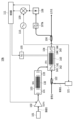
- Fig. 1 is a block diagram showing an example of the configuration of a wavelength conversion device 10 according to the first embodiment.
- the wavelength conversion device 10 shown in Fig. 1 illustratively includes a pumping light source 101, an erbium-doped optical fiber amplifier (EDFA) 102, a first wavelength converter 103, and a second wavelength converter 104.
- EDFA erbium-doped optical fiber amplifier
- the first wavelength converter 103 generates the second harmonic of the pump light incident from the EDFA 102, i.e., light with a frequency that is twice the frequency of the pump light (in other words, 1/2 the wavelength of the pump light), by, for example, SHG, which is one of the nonlinear optical effects.
- SHG the light equivalent to the second harmonic
- SH light the light equivalent to the second harmonic
- the first wavelength converter 103 that generates the SH light may be referred to as an SHG module 103, and illustratively includes a first spatial optical system 131, a first PPLN waveguide 132, and a second spatial optical system 133.
- the first spatial optical system 131 spatially guides the pump light incident from the EDFA 102 to the input port of the first wavelength converter 103 to the first PPLN waveguide 132.
- the first PPLN waveguide 132 is an example of a second-order nonlinear optical element that uses a nonlinear optical medium with a periodically poled structure, and generates SH light in response to the pump light by SHG as described above.
- the second spatial optical system 133 spatially guides the SH light generated in the first PPLN waveguide 132 to the output port of the first wavelength converter 103.
- the output port of the SHG module 103 is illustratively connected to the first input port of the second wavelength converter 104, and the SH light output from the SHG module 103 is input to the second wavelength converter 104.
- the second wavelength converter 104 can operate, for example, as an OPA that uses parametric fluorescence, which is one of the nonlinear optical effects, and amplifies the signal light (e.g., WDM signal light) input through the second input port by the SH light input through the first input port.
- OPA optical photoelectron emission detector
- the second wavelength converter 104 functioning as an OPA may be referred to as an OPA module 104.
- the OPA module 104 illustratively includes a third spatial optical system 141, a first dichroic mirror 142, a second PPLN waveguide 143, a fourth spatial optical system 144, and a second dichroic mirror 145.
- the third spatial optical system 141 for example, combines the SH light input from the SHG module 103 to the first input port and the signal light input to the second input port, and spatially guides the combined light to the second PPLN waveguide 143.
- the signal light passes through the first dichroic mirror 142 and is coupled to the second PPLN waveguide 143, and the SH light is reflected by the first dichroic mirror 142 and is coupled to the second PPLN waveguide 143. Therefore, the spatial optical system 141 and the dichroic mirror 142 may be understood to constitute, for example, a "dichroic mirror type multiplexer.”
- the second PPLN waveguide 143 is an example of a second-order nonlinear optical element using a nonlinear optical medium with a periodically poled structure.
- the periodically poled structure in the second PPLN waveguide 143 illustratively satisfies a pseudo-phase matching condition between the input signal light and SH light and the output converted light. Therefore, the second PPLN waveguide 143 is capable of parametrically amplifying the signal light by using the SH light as the pump light, for example.
- the fourth spatial optical system 144 outputs the amplified signal light from the output light of the second PPLN waveguide 143 to the optical branching coupler 106.
- the amplified signal light passes through the second dichroic mirror 145 and is output to the optical branching coupler 106, and the SH light is reflected by the second dichroic mirror 145 and emitted to the outside of the OPA module 104. Therefore, the spatial optical system 144 and the dichroic mirror 145 may be understood to constitute, for example, a "dichroic mirror type splitter.”
- the OPA module 104 is thermally coupled to the TEC 105, and for example, the controller 111 can control the TEC 105 to control the temperature of the OPA module 104.
- a nonlinear optical medium such as LiNbO3 , LiTaO3 , LiNb (x) Ta (1-x) O3 (0 ⁇ x ⁇ 1), or any of these containing at least one type selected from the group consisting of Mg, Zn, Sc, and In as an additive may be used.
- the optical branching coupler 106 is illustratively a tap with a branching ratio of approximately 1/100 to 1/10, and branches off a portion of the output light from the OPA module 104 (e.g., approximately 1% to 10% of the optical intensity) and outputs it to the wavelength separation filter 107.
- the remaining light intensity is output as output light from the OPA module 104.
- the output light from the OPA module 104 may include, for example, amplified signal light, converted light of the signal light, and amplified spontaneous emission (ASE) light, which will be described later.
- ASE amplified spontaneous emission
- the wavelength separation filter 107 is, for example, a bandpass filter (BPF) type optical filter that transmits light of a specific wavelength in the wavelength band of the branched light from the optical branching coupler 106 to the light intensity detector 108 as an example of monitor light, and blocks light of other wavelengths.
- BPF bandpass filter
- the transmission bandwidth of the wavelength separation filter 107 is, for example, about 1 nm. However, this is not limited to this, and the transmission bandwidth of the wavelength separation filter 107 is not limited as long as the filter has a characteristic in which the amount of light changes in the output in response to the oscillation of the central transmission wavelength, which will be described later.
- the wavelength separation filter 107 is, as a non-limiting example, a fiber Bragg grating (FBG) type optical filter, and its central transmission wavelength can be electrically tunable.
- the wavelength separation filter 107 can periodically change the central transmission wavelength (in other words, vibrate according to the frequency of the AC signal) by an AC signal supplied from the AC signal source 110.
- the light intensity detector 108 detects, for example, the intensity of light transmitted through the wavelength separation filter 107.
- the central transmission wavelength of the wavelength separation filter 107 is vibrated by an AC signal, the amount of light transmitted through the wavelength separation filter 107 periodically varies in response to the vibration.
- the monitor light output from the wavelength separation filter 107 is frequency modulated by the AC signal. Therefore, a modulated signal component corresponding to the frequency of the AC signal appears in the output (e.g., a DC voltage signal) of the light intensity detector 108.
- the multiplier 109 synchronously detects the modulated signal component in the output of the optical intensity detector 108 by multiplying the output of the optical intensity detector 108 by a signal synchronized with the AC signal of the AC signal source 110.
- the multiplier 109 performs lock-in detection (or first-order differential detection) of the output of the optical intensity detector 108 using a reference signal with a frequency that is one time the frequency of the AC signal supplied to the wavelength separation filter 107.
- the modulated signal component is demodulated by this lock-in detection, and a differential signal equivalent to the first derivative of the intensity change, in other words, a signal indicating the slope of the intensity change, is obtained. Therefore, the multiplier 109 may be understood to correspond, for example, to a "differential signal generator” that generates a differential signal equivalent to the first derivative of the intensity change, or a “slope detector” that detects the slope of the intensity change.
- the AC signal source 110 exemplarily supplies an AC signal, which is an example of a periodic signal that periodically changes the central transmission wavelength of the wavelength separation filter 107 as described above, to the wavelength separation filter 107.
- the frequency of the AC signal may be selected, for example, based on the response characteristics in lock-in detection, which will be described later, and is exemplarily a frequency on the order of 10 kHz.
- the light intensity detector 108, multiplier 109, and AC signal source 110 described above may be understood to constitute a non-limiting example of a "detection circuit" that detects the light intensity and the slope of the change in light intensity described above.
- the controller 111 is an example of a control circuit, and for example, controls the temperature of the TEC 105 and the amplification gain of the EDFA 102 individually based on the light intensity obtained by the light intensity detector 108 and the slope of the light intensity change obtained by the multiplier 109.
- "Individually control” may be understood to include a situation in which either the temperature of the TEC 105 or the amplification gain of the EDFA 102 is the object of control, and a situation in which both are the object of control.
- the controller 111 individually controls the temperature of the TEC 105 and the amplification gain of the EDFA 102 to keep the intensity and the slope of the intensity change constant, in other words, to minimize the changes in the intensity and the slope.
- the temperature of the OPA module 104 is controlled in response to the temperature control of the TEC 105, and the power of the pump light input to the SHG module 103 is controlled in response to the amplification gain control of the EDFA 102. Therefore, the SH light power input to the OPA module 104 is controlled in response to the amplification gain control of the EDFA 102.
- PID control Proportional-Integral-Differential control
- PID control Proportional-Integral-Differential control
- the pump light output from the pump light source 101 is subjected to power control by the EDFA 102 and then input to the SHG module 103.
- SH light of the pump light is generated by SHG in the first PPLN waveguide 132.
- the SH light of the pump light is input to the OPA module 104.
- the converted light generated by the PPLN waveguide 143 is output to a dichroic mirror type splitter together with the WDM signal into which the pump light is multiplexed.
- the pump light is split from the output light of the PPLN waveguide 143, and the remaining light (e.g., amplified WDM signal light + converted light of the WDM signal light + ASE light) is output to the optical branching coupler 106 as the output light of the OPA module 104.
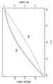
- Figure 3 is a graph showing an example of the change in wavelength conversion band with respect to the change in operating temperature of the OPA module 104.
- a method of controlling the operating temperature of the OPA module 104 by monitoring the entire band of the converted light may be considered, but this may increase the number of parts and complicate control. Also, if the power of the signal light input to the OPA module 104 fluctuates, the intensity of the converted light will also fluctuate accordingly, so control may become even more complicated if the OPA module 104 is assumed to be input with light from outside.
- the characteristics of the PPLN waveguide 143 are utilized to control the operating temperature of the OPA module 104.
- light in a wavelength region having a specific bandwidth converted from the excitation light by parametric fluorescence is used as the monitor light.
- the spectral shape of the converted light band can be controlled. For example, as shown in FIG. 2B, when the wavelength band of the input WDM signal light is 1528-1544 nm, the WDM signal light is wavelength-converted to converted light of the wavelength band 1546-1562 nm.
- the central transmission wavelength ( ⁇ BPF ) of the wavelength separation filter 107 may be set to a wavelength that does not overlap with either the wavelength bands 1528-1544 nm or 1546-1562 nm and is close to the converted light band 1546-1562 nm, for example, a wavelength of 1563 nm on the long wavelength side where the WDM signal light is not allocated.
- This wavelength of 1563 nm is a non-limiting example of a wavelength in a band where neither the WDM signal light nor the converted light is allocated.
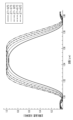
- Figure 4 is a graph showing an example of the change in intensity and slope with respect to temperature for light of a specific wavelength (e.g., near 1545 nm) in the ASE light spectrum when the temperature of the wavelength conversion device 10 changes while the excitation light power is constant.
- reference numeral 401 indicates the change in intensity with respect to temperature change (left vertical axis)
- reference numeral 402 indicates the change in slope with respect to temperature change (right vertical axis).
- the change in intensity is normalized.
- the temperature is as shown in Figure 3.
- the controller 111 performs calculations for PID control, for example, based on the optical intensity detected by the optical intensity detector 108 and the lock-in signal (differential signal) detected by the multiplier 109.
- the controller 111 then performs feedback control of the TEC 105 and the EDFA 102 (amplification gain) individually based on the results of the calculations. This makes it possible to stabilize the optical intensity at around 0.2 dB in the converted optical band of the WDM signal light, for example.
- wavelength conversion device 10 of the first embodiment light of a specific wavelength (for example, ASE light of wavelength ⁇ BPF ) is separated by the wavelength separation filter 107 from the output light generated by parametric fluorescence in the OPA module 104.
- the optical intensity and the slope of the optical intensity change of the separated wavelength are detected by the optical intensity detector 108 and the multiplier 109, respectively, and the temperature and pumping light power of the OPA module 104 are individually controlled by the controller 111 based on the detection results.
- the spectral shape of the converted light band by parametric fluorescence can be controlled to a constant value, regardless of whether or not signal light is input to the OPA module 104. Therefore, it is possible to operate the wavelength conversion device 10 stably and for a long time under optimal or suitable operating conditions.
- the central transmission wavelength of the wavelength separation filter 107 (in other words, the wavelength ⁇ BPF of the monitor light) to a wavelength that does not overlap with the converted light band of the WDM signal light, appropriate monitoring operation can be achieved without interfering with the converted light of the WDM signal light.
- an FBG type optical filter is shown as an example of the wavelength separation filter 107 that can electrically tune the central transmission wavelength.
- a wavelength separation filter 107 with an electrically tunable central transmission wavelength may be realized by combining a narrowband BPF with an optical interferometer and modulating the optical path difference of the optical interferometer.
- a wavelength that is longer than the conversion band is selected as the wavelength of the monitor light ( ⁇ BPF ), but a wavelength that is shorter than the conversion band (e.g., 1545 nm) may be selected.
- a wavelength that is shorter than the conversion band e.g., 1545 nm
- Second Embodiment 5 is a block diagram showing a configuration example of a wavelength conversion device 10A according to a second embodiment.
- components with the same reference numerals as those already described may be understood to be the same as or similar to the already described components, unless otherwise specified.
- the wavelength conversion device 10A differs from the configuration illustrated in FIG. 1 in that it additionally includes a control light source 121 and an optical multiplexing coupler 122 provided on the input side of the OPA module 104, and that a wavelength separation filter 107A is provided instead of the wavelength separation filter 107.
- the control light source 121 is configured, for example, using a semiconductor laser, and generates control light.
- the wavelength of the control light will be described later in relation to the central transmission wavelength of the wavelength separation filter 107A.
- the optical multiplexing coupler 122 multiplexes the control light output from the control light source 121 with the signal light input to the OPA module 104.
- the wavelength separation filter 107A is a BPF type optical filter similar to the wavelength separation filter 107 in the first embodiment, and transmits light of a specific wavelength in the wavelength band of the branched light from the optical branching coupler 106 to the light intensity detector 108 as an example of monitor light.
- the transmission bandwidth of the wavelength separation filter 107A is, for example, about 1 nm, as in the first embodiment. However, this is not limited, and the transmission bandwidth of the wavelength separation filter 107A is not limited as long as the filter has a characteristic in which the light quantity changes in the output in response to the oscillation of the center frequency of the control light, which will be described later.
- the wavelength separation filter 107A does not need to have a variable central transmission wavelength, and illustratively has a fixed central transmission wavelength.
- a filter with a variable central transmission wavelength may be applied to the wavelength separation filter 107A, but the central transmission wavelength may not be variable (e.g., vibrated).
- the AC signal source 110 differs from the configuration illustrated in FIG. 1 in that it is electrically connected to the control light source 121 and supplies the control light source 121 with an AC signal, which is an example of a periodic signal that periodically changes the center frequency of the control light.
- This AC signal causes the center frequency of the control light input to the OPA module 104 via the optical multiplexing coupler 122 to oscillate.
- the wavelength conversion device 10A is configured to apply frequency modulation for lock-in detection to the control light input to the wavelength separation filter 107A.
- the multiplier 109 performs lock-in detection of the modulated signal component in the output of the optical intensity detector 108 by multiplying the output of the optical intensity detector 108 by a signal synchronized with the AC signal of the AC signal source 110.
- the light intensity detector 108, the multiplier 109, and the AC signal source 110 may be understood to constitute a non-limiting example of a "detection circuit" that detects the light intensity and the slope of the change in light intensity described above.
- the frequency of the AC signal that oscillates the center frequency of the control light may be selected based on the response characteristics in lock-in detection, as in the first embodiment, and is illustratively a frequency on the order of 10 kHz.
- the intensity of the control light output from the control light source 121 may be set to an intensity higher than the ASE light level, for example.
- the noise resistance of the light intensity detection and tilt detection can be improved more than in the first embodiment.
- the wavelength (frequency: ⁇ i ) of the control light output from the control light source 121 is, for example, the same as the central transmission wavelength of the wavelength separation filter 107 A. In other words, the wavelength of the control light matches the wavelength of the light separated by the wavelength separation filter 107 A.
- the wavelength of the control light is set to 1563 nm.
- This wavelength of 1563 nm is a non-limiting example of a wavelength that does not overlap with the converted light band of the WDM signal light and is deviated from the converted light band to the long wavelength side.
- the control light that has been frequency modulated by the AC signal from the AC signal source 110 is input to the wavelength separation filter 107A via the OPA module 104 and the optical branching coupler 106.
- the wavelength separation filter 107A whose central transmission wavelength is set to the wavelength of the control light, transmits the control light input from the optical branching coupler 106 to the optical intensity detector 108, which detects the intensity of the control light.
- the slope of the change in intensity of the control light is detected by lock-in detection using the multiplier 109 and the AC signal source 110.
- the controller 111 individually controls (e.g., PID control) the excitation light power of the excitation light source 101 and the temperature of the OPA module 104 based on the detected intensity of the control light and the slope of the intensity change.
- PID control e.g., PID control
- This control keeps the spectral shape of the converted light band constant, or minimizes changes in the spectral shape.
- the light intensity in the converted light band can be stabilized to about 0.2 dB.
- the wavelength of the control light matches the central transmission wavelength of the wavelength separation filter 107A, but the wavelength of the control light may not match the central transmission wavelength of the wavelength separation filter 107A.
- the frequency of the control light is represented by ⁇ 1
- the frequency ⁇ i of the light converted from the control light by parametric fluorescence in the OPA module 104 is represented by the following Equation 2 using the frequency 2 ⁇ 0 of the excitation light.
- ⁇ i 2 ⁇ 0 - ⁇ 1 (2)
- the converted light with frequency ⁇ i also contains a modulated component according to the frequency modulation applied by the AC signal source 110. Therefore, the central transmission wavelength of the wavelength separation filter 107A may be set to a wavelength corresponding to the frequency ⁇ i of the converted light of the control light.
- the combination of the wavelength ⁇ CONT of the control light and the central transmission wavelength ⁇ BPF of the wavelength separation filter 107A may be either (a) or (b) below.
- ⁇ CONT 1563 nm
- ⁇ BPF 1527 nm
- ⁇ CONT 1527 nm
- ⁇ BPF 1563 nm
- the central transmission wavelength of the wavelength separation filter 107A may be set to the wavelength of the control light, or may be set to the wavelength of the light converted by the parametric fluorescence of the control light.
- the wavelength of the control light and the central transmission wavelength of the wavelength separation filter 107A may be set to either of two wavelengths corresponding to the frequencies ⁇ 1 and ⁇ i , respectively, that satisfy the above-mentioned formula 2.
- the control light included in the output light of the OPA module 104 may be cut by, for example, an optical filter provided separately on the output side of the optical branching coupler 106.
- the control light may be separated from the output light of the OPA module 104 in the WDM filter and input to the wavelength separation filter 107A.
- the pump light power is controlled by controlling the amplification gain of the EDFA 102.
- the pump light power may be controlled by, for example, output light power control for the pump light source 101 having a variable output light power, or optical attenuation control of a variable optical attenuator (VOA) provided between the EDFA 102 and the SHG module 103.
- VOA variable optical attenuator
- the EDFA 102 may be omitted.
- control for example, tracking operation
- the output optical power of the pumping light source 101 in addition to controlling the amplification gain of the EDFA 102, it is possible to expand the controllable range of the pumping light power, for example.
- control for example, tracking operation
- the response speed of the pump light source 101 or the VOA is faster than the response speed of the EDFA 102.
- both the temperature and the excitation light power are controlled, but either the temperature or the excitation light power may be controlled.
- the temperature of the OPA module 104 may be controlled.
- the object to be controlled may be the light intensity (e.g., the excitation light power).
- the spectral shape can be uniquely determined including the shift in the light intensity direction, and the control time for stabilizing the spectral shape can be shortened.
- the optical branching coupler 106 may be replaced with, for example, a WDM filter that separates the signal light or converted light from the light of the specific wavelength described above (in other words, the monitor light).
- the wavelength separation filter 107 or 107A having BPF characteristics may be realized, for example, by a combination of a long-pass filter and a short-pass filter.
- the spectral shape of the signal light in the band after conversion by parametric fluorescence is controlled to be constant.
- the spectral shape of the signal light band before conversion by parametric fluorescence may be controlled to be constant.
- a central transmission wavelength ( ⁇ BPF ) of the wavelength separation filter 107 or 107A may be set to 1527 nm, which is shorter than the signal light band of 1528 to 1544 nm. This setting makes it possible to control the "spectral shape of the signal light band" to a constant value when operating as an optical parametric amplifier.
- This disclosure is expected to be utilized, for example, in the stable operation of optical elements that utilize nonlinear optical effects, and is useful in optical communication systems, optical measurement systems, and amplification technology for optical communication in general.
Landscapes
- Physics & Mathematics (AREA)
- Nonlinear Science (AREA)
- General Physics & Mathematics (AREA)
- Optics & Photonics (AREA)
- Optical Modulation, Optical Deflection, Nonlinear Optics, Optical Demodulation, Optical Logic Elements (AREA)
Abstract
Un dispositif de conversion de longueur d'onde (10) selon la présente divulgation comprend : un convertisseur de longueur d'onde (104) qui utilise un milieu optique non linéaire (143) ; un filtre de séparation de longueur d'onde (107) qui sépare une partie de la lumière de sortie générée dans le convertisseur de longueur d'onde (104) par fluorescence paramétrique en réponse à une entrée de lumière d'excitation vers le milieu optique non linéaire (143) ; un circuit de détection (108, 109, 110) qui détecte l'intensité de la lumière séparée par le filtre de séparation de longueur d'onde (107) et le gradient du changement de l'intensité ; et un circuit de commande (111) qui commande individuellement l'intensité de la lumière d'excitation et la température du convertisseur de longueur d'onde (104) sur la base de l'intensité et du gradient détectés.
Priority Applications (1)
| Application Number | Priority Date | Filing Date | Title |
|---|---|---|---|
| PCT/JP2023/030046 WO2025041234A1 (fr) | 2023-08-21 | 2023-08-21 | Dispositif de conversion de longueur d'onde et procédé de commande |
Applications Claiming Priority (1)
| Application Number | Priority Date | Filing Date | Title |
|---|---|---|---|
| PCT/JP2023/030046 WO2025041234A1 (fr) | 2023-08-21 | 2023-08-21 | Dispositif de conversion de longueur d'onde et procédé de commande |
Publications (1)
| Publication Number | Publication Date |
|---|---|
| WO2025041234A1 true WO2025041234A1 (fr) | 2025-02-27 |
Family
ID=94731656
Family Applications (1)
| Application Number | Title | Priority Date | Filing Date |
|---|---|---|---|
| PCT/JP2023/030046 Pending WO2025041234A1 (fr) | 2023-08-21 | 2023-08-21 | Dispositif de conversion de longueur d'onde et procédé de commande |
Country Status (1)
| Country | Link |
|---|---|
| WO (1) | WO2025041234A1 (fr) |
Citations (3)
| Publication number | Priority date | Publication date | Assignee | Title |
|---|---|---|---|---|
| JP2020076834A (ja) * | 2018-11-06 | 2020-05-21 | 日本電信電話株式会社 | 波長変換装置 |
| WO2023037560A1 (fr) * | 2021-09-13 | 2023-03-16 | 日本電信電話株式会社 | Convertisseur de longueur d'onde et son procédé de commande |
| WO2023084621A1 (fr) * | 2021-11-09 | 2023-05-19 | 日本電信電話株式会社 | Dispositif de conversion de longueur d'onde |
-
2023
- 2023-08-21 WO PCT/JP2023/030046 patent/WO2025041234A1/fr active Pending
Patent Citations (3)
| Publication number | Priority date | Publication date | Assignee | Title |
|---|---|---|---|---|
| JP2020076834A (ja) * | 2018-11-06 | 2020-05-21 | 日本電信電話株式会社 | 波長変換装置 |
| WO2023037560A1 (fr) * | 2021-09-13 | 2023-03-16 | 日本電信電話株式会社 | Convertisseur de longueur d'onde et son procédé de commande |
| WO2023084621A1 (fr) * | 2021-11-09 | 2023-05-19 | 日本電信電話株式会社 | Dispositif de conversion de longueur d'onde |
Non-Patent Citations (1)
| Title |
|---|
| SHIMIZU SHIMPEI, KOBAYASHI TAKAYUKI, KAZAMA TAKUSHI, UMEKI TAKESHI, NAKAMURA MASANORI, ENBUTSU KOJI, KASHIWAZAKI TAKAHIRO, HAMAOKA: "Wideband Optical Parametric Amplification of 8.375-THz WDM Signal Using Cascaded PPLN Waveguides With Reused Pump Light", JOURNAL OF LIGHTWAVE TECHNOLOGY, IEEE, USA, vol. 41, no. 24, 15 December 2023 (2023-12-15), USA, pages 7399 - 7407, XP093281641, ISSN: 0733-8724, DOI: 10.1109/JLT.2023.3299017 * |
Similar Documents
| Publication | Publication Date | Title |
|---|---|---|
| CN112969960B (zh) | 波长转换装置 | |
| US5946129A (en) | Wavelength conversion apparatus with improved efficiency, easy adjustability, and polarization insensitivity | |
| US7801189B2 (en) | Cross modulation-based opto-electronic oscillator with tunable electro-optic optical whispering gallery mode resonator | |
| US7123800B2 (en) | Integrated loop resonator with adjustable couplings and methods of using the same | |
| KR101417061B1 (ko) | 레이저광 발생 장치 | |
| US20200280172A1 (en) | Tunable laser and laser transmitter | |
| JPH09511847A (ja) | チャネル導波管から成る接合スプリッタおよび用途 | |
| JP2002311467A (ja) | レーザー光発生装置及び方法 | |
| JP5023462B2 (ja) | THz波発生装置 | |
| JP7659211B2 (ja) | 波長変換装置 | |
| JP7473850B2 (ja) | 波長変換装置 | |
| JP2015132774A (ja) | 波長変換光源 | |
| Ghoumid et al. | Tunable filter based on cavity electro-optic modulation for DWDM applications | |
| JP5550040B2 (ja) | 光制御遅延器及び分光装置 | |
| WO2025041234A1 (fr) | Dispositif de conversion de longueur d'onde et procédé de commande | |
| JP7810905B2 (ja) | 波長変換器およびその制御方法 | |
| WO2004107033A1 (fr) | Generateur de peigne de frequences | |
| US12401170B2 (en) | Methods and systems for pulsed beam phase locking | |
| JP7684605B2 (ja) | 波長変換装置 | |
| JP2002076507A (ja) | 周波数安定化半導体レーザ装置 | |
| WO2024121937A1 (fr) | Amplificateur optique | |
| JP6093246B2 (ja) | 中赤外波長変換光源 | |
| JP7773105B2 (ja) | 光増幅器 | |
| US20260128565A1 (en) | Offset locked dual laser system for mts spectroscopy | |
| Zhang et al. | Silicon-based on-chip electrically tunable phase-shifted waveguide Bragg grating for integrated microwave photonic applications |
Legal Events
| Date | Code | Title | Description |
|---|---|---|---|
| 121 | Ep: the epo has been informed by wipo that ep was designated in this application |
Ref document number: 23949695 Country of ref document: EP Kind code of ref document: A1 |
|
| ENP | Entry into the national phase |
Ref document number: 2025541190 Country of ref document: JP Kind code of ref document: A |
|
| WWE | Wipo information: entry into national phase |
Ref document number: 2025541190 Country of ref document: JP |
|
| NENP | Non-entry into the national phase |
Ref country code: DE |