WO2025041224A1 - 回転電機および回転電機の駆動方法 - Google Patents
回転電機および回転電機の駆動方法 Download PDFInfo
- Publication number
- WO2025041224A1 WO2025041224A1 PCT/JP2023/029997 JP2023029997W WO2025041224A1 WO 2025041224 A1 WO2025041224 A1 WO 2025041224A1 JP 2023029997 W JP2023029997 W JP 2023029997W WO 2025041224 A1 WO2025041224 A1 WO 2025041224A1
- Authority
- WO
- WIPO (PCT)
- Prior art keywords
- drive unit
- rotary drive
- electric machine
- stator
- rotor
- Prior art date
- Legal status (The legal status is an assumption and is not a legal conclusion. Google has not performed a legal analysis and makes no representation as to the accuracy of the status listed.)
- Pending
Links
Images


Classifications
-
- H—ELECTRICITY
- H02—GENERATION; CONVERSION OR DISTRIBUTION OF ELECTRIC POWER
- H02K—DYNAMO-ELECTRIC MACHINES
- H02K16/00—Machines with more than one rotor or stator
-
- H—ELECTRICITY
- H02—GENERATION; CONVERSION OR DISTRIBUTION OF ELECTRIC POWER
- H02K—DYNAMO-ELECTRIC MACHINES
- H02K19/00—Synchronous motors or generators
- H02K19/02—Synchronous motors
- H02K19/10—Synchronous motors for multi-phase current
-
- H—ELECTRICITY
- H02—GENERATION; CONVERSION OR DISTRIBUTION OF ELECTRIC POWER
- H02K—DYNAMO-ELECTRIC MACHINES
- H02K21/00—Synchronous motors having permanent magnets; Synchronous generators having permanent magnets
- H02K21/12—Synchronous motors having permanent magnets; Synchronous generators having permanent magnets with stationary armatures and rotating magnets
- H02K21/24—Synchronous motors having permanent magnets; Synchronous generators having permanent magnets with stationary armatures and rotating magnets with magnets axially facing the armatures, e.g. hub-type cycle dynamos
Definitions
- This disclosure relates to a rotating electric machine and a method for driving the rotating electric machine.
- Rotating electric machines used in electric vehicles are required to have high performance in terms of the maximum torque and maximum output required to drive the vehicle.
- general rotating electric machines that meet these requirements have a problem in that their efficiency drops in the low torque and low output ranges where they are often used in practice.
- This disclosure has been made to solve the above-mentioned problems, and aims to provide a rotating electric machine that satisfies the maximum performance required without increasing size and improves efficiency in the low torque range.
- the rotating electric machine of the present disclosure has a frame, a rotating shaft rotatably supported by the frame, and a first rotating drive unit and a second rotating drive unit built into the frame and sharing the rotating shaft.
- the first rotating drive unit is a radial gap type rotating drive unit including a first stator having a first stator core of an annular shape fixed to the frame and a plurality of first stator coils installed on the first stator core, and a first rotor fastened to the rotating shaft and having a first rotor core arranged radially with a gap from the first stator and a first rotor coil installed on the first rotor core
- the second rotating drive unit is an axial gap type rotating drive unit including a second stator fixed to the frame and a second rotor having a second rotor core fastened to the rotating shaft and arranged axially with a gap from the second stator on the first rotating drive unit side, and a second rotor magnet installed on the second rotor core.
- the second rotary drive unit is an axial gap type rotary drive unit that includes a second stator fixed to the frame, a second rotor core that is fastened to the rotating shaft and arranged axially on the first rotary drive unit side relative to the second stator through a gap, and a second rotor that has a second rotor magnet installed on the second rotor core, so that it is possible to satisfy the required maximum performance without increasing the size and improve efficiency in the low torque range.
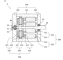
- FIG. 1 is a cross-sectional view of a rotating electric machine according to a first embodiment.
- 3 is a cross-sectional view of a first stator according to the first embodiment.
- FIG. FIG. 4 is a side view of a second load rotor according to the first embodiment. 4 is a diagram for explaining the operation of the rotating electric machine according to the first embodiment;
- FIG. 11 is a cross-sectional view of a rotating electric machine according to a second embodiment.
- FIG. FIG. 11 is a cross-sectional view of a first rotor according to a second embodiment.
- FIG. 11 is a cross-sectional view of a rotating electric machine according to a third embodiment.
- FIG. 11 is a cross-sectional view of a first rotor according to embodiment 3.
- FIG. 11 is a cross-sectional view of a first rotor according to embodiment 3.
- FIG. 11 is a cross-sectional view of a rotating electric machine according to a fourth embodiment.
- FIG. 11 is a cross-sectional view of a second stator according to embodiment 4.
- FIG. 13 is a cross-sectional view of a rotating electric machine according to a fifth embodiment.
- FIG. 13 is a cross-sectional view of a rotating electric machine according to a sixth embodiment.
- Fig. 1 is a cross-sectional view of a rotating electric machine according to a first embodiment.
- Fig. 1 is a cross-sectional view in a direction parallel to a rotating shaft, which will be described later.
- the rotating shaft is connected to a load (not shown) on the right side of Fig. 1. Therefore, in Fig. 1, the right side is referred to as the load side, and the left side is referred to as the anti-load side.
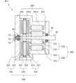
- the rotating electric machine 1 of this embodiment includes a first rotary drive unit 200 arranged on the load side and a second rotary drive unit 300 arranged on the counter-load side.
- the first rotary drive unit 200 and the second rotary drive unit 300 are built into one frame 100 and share one rotating shaft 20.
- the rotating shaft 20 is rotatably supported by the load side bearing 30 and the counter-load side bearing 40 relative to the frame 100.
- the load side end of the rotating shaft 20 is extended to the outside of the frame 100 and connected to the load.
- the direction parallel to the rotating shaft 20 is referred to as the axial direction
- the direction perpendicular to the rotating shaft 20 is referred to as the radial direction
- the direction in which the rotating shaft 20 rotates is referred to as the circumferential direction.
- the inner diameter side is the direction approaching the rotating shaft 20 in the radial direction
- the outer diameter side is the direction moving away from the rotating shaft 20 in the radial direction.
- the frame 100 is composed of a cylindrical central frame 101 that covers the first rotary drive unit 200 and the second rotary drive unit 300 on the radial outside, a load side plate 102 that covers the load side end of the central frame 101, and a counter-load side plate 103 that covers the counter-load side end.
- a resolver rotor 51 which is a rotational position sensor that detects the rotational position of the rotating shaft 20, is fastened to the counter-load side end of the rotating shaft 20.
- a resolver stator 52 is fastened to the counter-load side plate 103 and is disposed with a gap between the resolver rotor 51 and the resolver stator 52.
- a resolver cover 53 that covers the resolver rotor 51 and the resolver stator 52 is attached to the counter-load side plate 103.
- the first rotary drive unit 200 is an induction machine and is arranged on the load side within the rotating electric machine 1.
- the first rotary drive unit 200 has a first rotor 210 fastened to the rotating shaft 20 and a first stator 220 fastened to the central frame 101.
- the first rotor 210 and the first stator 220 are arranged with a gap in the radial direction.
- the first rotor 210 is composed of a first rotor core 211 of annular shape fastened to the rotating shaft 20 and a first rotor coil 212.
- the first rotor core 211 has a main body part of an annular shape and 59 teeth protruding from this main body part to the outer diameter side.
- the first rotor coil 212 is a cage-type conductor arranged in the slots, which are the spaces between the teeth.
- FIG. 2 is a cross-sectional view of the first stator according to this embodiment.
- the first stator 220 is composed of a first stator core 221 in a circular ring shape fastened to the central frame 101, and a first stator coil 222.
- the first stator core 221 has a circular ring-shaped main body and 48 teeth protruding from the main body to the inner diameter side.
- the first stator coil 222 is wound around the teeth in a distributed winding manner.
- the first rotary drive unit 200 thus configured is an 8-pole radial gap type squirrel-cage induction machine. Note that the radial gap type is a structure in which a gap exists between the rotor and stator in the radial direction.
- the second rotary drive unit 300 is a permanent magnet synchronous rotating machine, and is arranged on the anti-load side within the rotating electric machine 1.
- the second rotary drive unit 300 has a load side second rotor 310 and an anti-load side second rotor 320 fastened to the rotating shaft 20, and a second stator 330 fastened to the central frame 101.
- the load side second rotor 310 is arranged on the axial load side of the second stator 330 via a gap.
- the anti-load side second rotor 320 is arranged on the axial anti-load side of the second stator 330 via a gap.
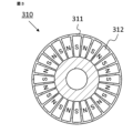
- the load side second rotor 310 is composed of a disk-shaped load side second rotor core 311 fastened to the rotating shaft 20, and a load side second rotor magnet 312.
- the load side second rotor magnet 312 is embedded in the surface of the load side second rotor core 311 that faces the second stator 330.
- the load side second rotor magnets 312 are sector-shaped, and 24 of them are arranged at equal intervals in the circumferential direction, with the north and south poles facing alternately in the axial direction.
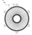
- FIG. 3 is a side view of the load side second rotor 310 according to this embodiment.
- FIG. 3 is a side view of the load side second rotor 310 as seen from the second stator 330 side.
- the load side second rotor 310 has 24 load side second rotor magnets 312 arranged at equal intervals in the circumferential direction on a disk-shaped load side second rotor core 311.
- the anti-load side second rotor 320 is composed of a disk-shaped anti-load side second rotor core 321 fastened to the rotating shaft 20, and an anti-load side second rotor magnet 322.
- the anti-load side second rotor magnet 322 is embedded in the surface of the anti-load side second rotor core 321 facing the second stator 330.
- the anti-load side second rotor magnets 322 are sector-shaped, and 24 of them are arranged at equal intervals in the circumferential direction, with the north poles and south poles alternately facing the axial direction.
- the side of the anti-load side second rotor 320 seen from the second stator 330 side is similar to the side of the load side second rotor 310 shown in FIG. 3.
- the load side second rotor magnet 312 of the load side second rotor 310 and the anti-load side second rotor magnet 322 of the anti-load side second rotor 320 are arranged so that the magnetic poles of the magnets at the same position in the circumferential direction face the second stator 330 with their north and south poles facing each other.
- the second stator 330 is composed of a circular ring-shaped second stator base 331 fastened to the central frame 101, and a second stator coil 332.
- the second stator base 331 has 72 slots formed at equal intervals in the circumferential direction at a mechanical angle of 5 degrees.
- the second stator coil 332 is wound around these 72 slots at a 6-slot pitch.
- the second rotation drive unit 300 thus configured is an axial gap type permanent magnet synchronous rotating machine.
- the axial gap type is a structure in which a gap exists between a disk-shaped rotor and a stator in the axial direction.
- the frame 100, the rotating shaft 20, the second stator 330, and the second stator base 331 are non-magnetic and made of, for example, aluminum, resin, etc. These members are desirably made of resin, which is a non-conductive material, so that eddy current loss due to magnetic flux fluctuation does not occur.
- the first rotor core 211, the first stator core 221, the load side second rotor core 311, and the counter-load side second rotor core 321 are magnetic and made of, for example, laminated electromagnetic steel sheets.
- the first rotor coil 212, the first stator coil 222, and the second stator coil 332 are made by winding a conductor wire made of, for example, copper, aluminum, iron, etc.
- the load side second rotor magnet 312 and the counter-load side second rotor magnet 322 are permanent magnets, for example, rare earth magnets.
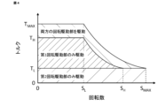
- Fig. 4 is a diagram showing the operation of the rotating electric machine according to this embodiment.
- the horizontal axis is rotation speed
- the vertical axis is torque.
- S MAX is the maximum rotation speed of the rotating electric machine 1
- S H is a threshold value on the high rotation speed side
- S L is a threshold value on the low rotation speed side, with S L ⁇ S H ⁇ S MAX .
- T MAX is the maximum torque of the rotating electric machine 1
- T H is a threshold value on the high torque side
- T L is a threshold value on the low torque side, with T L ⁇ T H ⁇ T MAX .
- the rotating electric machine 1 of this embodiment is driven only by the second rotary drive unit 300 when the torque is from 0 to T L regardless of the rotation speed.
- the rotating electric machine 1 is driven only by the first rotary drive unit 200 when the rotation speed is in the range from 0 to S L and the torque is from T L to T H.
- the rotating electric machine 1 is driven by both the first rotary drive unit 200 and the second rotary drive unit 300 when the rotation speed is in the range from 0 to S L and the torque is from T H to T MAX .
- the rotating electric machine 1 is driven only by the first rotary drive unit 200 in the rotation speed range from S L to S H and the torque range from T L to T H on the constant output curve. Moreover, the rotating electric machine 1 is driven by both the first rotary drive unit 200 and the second rotary drive unit 300 in the rotation speed range from S L to S MAX and the torque range from the constant output curve of T H to the constant output curve of T MAX.
- the torque distribution is such that the second rotational drive unit 300 always outputs torque T L and the first rotational drive unit 200 outputs the remaining required torque.
- T L is the maximum torque that the second rotational drive unit 300 can output
- T H is the maximum torque that the first rotational drive unit 200 can output.
- T MAX T L +T H
- T MAX is the maximum torque that the rotating electric machine 1 can output.
- S L which is a threshold value on the low rotational speed side
- S H which is a threshold value on the high rotational speed side
- S L which is a threshold value on the low rotational speed side
- S H which is a threshold value on the high rotational speed side
- frequent drive switching may occur.
- frequent drive switching can be avoided. For example, when the torque increases and decreases across the border line, frequent drive switching can be avoided by setting the threshold value that is the border line when the torque decreases to 95% of the threshold value that is the border line when the torque increases.
- the rotating electrical machine 1 when the torque is equal to or less than T L , it is driven only by the second rotary drive unit 300, which is an axial gap type permanent magnet synchronous rotating machine, and therefore it is possible to reduce iron loss caused by PWM carrier harmonics that are generated when the second rotary drive unit 300 is inverter driven, thereby improving efficiency in the low torque region.
- the second rotary drive unit 300 has permanent magnets as a field source in the load side second rotor 310 and the anti-load side second rotor 320, but since the second stator base 331 of the second stator 330 is made of a non-magnetic material, no stator iron loss occurs due to the rotating magnetic field generated by the rotor field. This improves the efficiency of the rotating electric machine 1.
- the first rotary drive unit 200 When only the second rotary drive unit 300 is driven, the first rotary drive unit 200 also rotates in conjunction with it. However, since the first rotary drive unit 200 is an induction machine, no electromagnetic loss occurs due to the interlocking rotation.
- the rotating electrical machine 1 is driven only by the first rotary drive unit 200.
- the region where only the first rotary drive unit 200, which is a cage induction machine, is driven is not a low torque region where efficiency is low. Therefore, it is possible to suppress the decrease in efficiency in the low torque region.
- the second rotary drive unit 300 also rotates in conjunction with it.
- the second rotary drive unit 300 is provided with a permanent magnet as a field source
- the second stator base 331 of the second stator 330 is made of a non-magnetic material, so that no stator iron loss occurs due to the rotating magnetic field generated by the rotor field magnet. Therefore, it is possible to improve the efficiency of the rotating electric machine 1.
- the rotating magnetic field generated between the first rotor 210 and the first stator 220 of the first rotary drive unit 200 interlinks with the load side second rotor core 311 of the second rotary drive unit 300.
- the rotating magnetic field generated in the first rotary drive unit 200 rotates at the same rotation speed as the load side second rotor core 311, it does not become an alternating magnetic field in the load side second rotor core 311.
- no iron loss occurs in the load side second rotor core 311. Therefore, even if the axial distance between the first rotary drive unit 200 and the second rotary drive unit 300 is shortened, the efficiency does not decrease. As a result, the rotating electric machine of this embodiment can be prevented from becoming large.
- the load side second rotor core 311 of the second rotary drive unit 300 is disposed closer to the first rotary drive unit 200 than the second stator 330.
- the second rotary drive unit 300 and the first rotary drive unit 200 rotate synchronously. Therefore, the load side second rotor core 311 shields the rotating magnetic field of the first rotary drive unit 200, so that the rotating magnetic field of the first rotary drive unit 200 does not interlink with the second stator 330.
- the rotating electric machine 1 of this embodiment can improve efficiency without increasing its size.
- the second rotary drive unit 300 which has a second stator base 331 made of a non-magnetic material and rotates using the field magnet of a permanent magnet, has high efficiency. In a region driven by both the first rotary drive unit 200 and the second rotary drive unit 300, the highly efficient second rotary drive unit 300 always generates maximum torque, thereby improving the maximum performance of the rotating electric machine 1.
- the second rotary drive unit 300 which is a permanent magnet synchronous rotating machine, is greatly influenced by the rotational position when it comes to control.
- the resolver rotor 51 which is a rotational position sensor, is disposed at the end of the rotating shaft 20 on the anti-load side. Therefore, since the resolver rotor 51 is disposed near the second rotary drive unit 300, it is less affected by the twisting of the rotating shaft 20, and the controllability of the second rotary drive unit 300 can be improved.
- the first rotary drive unit is an eight-pole radial gap type squirrel-cage induction machine.
- the first rotary drive unit is configured as a synchronous reluctance motor.
- FIG. 5 is a cross-sectional view of a rotating electric machine according to this embodiment.
- the configuration of the rotating electric machine according to this embodiment is similar to that of the rotating electric machine according to embodiment 1 shown in FIG. 1, but the configuration of the first rotary drive unit 200 is different from that of the first rotary drive unit according to embodiment 1.
- the first rotor 210 according to this embodiment is composed only of a first rotor core 211 having an annular shape fastened to the rotating shaft 20. This first rotor core 211 has a plurality of slits 213 formed therein that penetrate in the axial direction.
- FIG. 6 is a cross-sectional view of the first rotor according to this embodiment.
- FIG. 6 is a cross-sectional view in a direction perpendicular to the rotation axis.
- the first rotor 210 according to this embodiment has a plurality of slits 213 formed in the first rotor core 211. These slits 213 serve as flux barriers that form salient poles facing the inner diameter side. Eight sets of these flux barriers are formed at equal intervals in the circumferential direction.
- the rotating electric machine 1 according to this embodiment has the first rotary drive unit 200 configured as a synchronous reluctance motor.
- the rotating electric machine 1 of this embodiment is driven in the same way as the rotating electric machine of embodiment 1. Therefore, like the rotating electric machine of embodiment 1, it is possible to satisfy the maximum performance required without increasing the size and to improve efficiency in the low torque range.
- the first rotary drive unit is an eight-pole radial gap type squirrel-cage induction machine.
- the first rotary drive unit is configured as a switched reluctance motor.
- FIG. 7 is a cross-sectional view of a rotating electric machine according to this embodiment.
- the configuration of the rotating electric machine according to this embodiment is similar to the configuration of the rotating electric machine according to embodiment 1 shown in FIG. 1, but the configuration of the first rotary drive unit 200 is different from the configuration of the first rotary drive unit according to embodiment 1.
- the first stator 220 in the rotating electric machine of this embodiment is composed of a first stator core 221 in a circular ring shape fastened to the central frame 101, and a first stator coil 222.
- the first stator core 221 has a circular ring-shaped main body and 12 teeth protruding from this main body to the inner diameter side.
- the first stator coil 222 is wound around the teeth in a concentrated winding manner.
- the first rotor 210 in this embodiment is composed only of a first rotor core 211 fastened to the rotating shaft 20.
- This first rotor core 211 is composed of a ring-shaped main body and eight protrusions 214 protruding from the main body to the outer diameter side.
- FIG. 8 is a cross-sectional view of the first rotor according to this embodiment.
- FIG. 8 is a cross-sectional view in a direction perpendicular to the rotation axis.
- the first rotor 210 according to this embodiment has eight protrusions 214 protruding from the annular main body of the first rotor core 211 toward the outer diameter side.
- the eight protrusions 214 are formed at equal intervals in the circumferential direction.
- the rotating electric machine 1 according to this embodiment has the first rotary drive unit 200 configured as a switched reluctance motor.
- the rotating electric machine 1 of this embodiment is driven in the same way as the rotating electric machine of embodiment 1. Therefore, like the rotating electric machine of embodiment 1, it is possible to satisfy the maximum performance required without increasing the size and to improve efficiency in the low torque range.
- the second rotary drive unit is an axial gap type permanent magnet synchronous rotating machine having no magnetic body in the stator.
- the second rotary drive unit has a stator made of a magnetic body.
- FIG. 9 is a cross-sectional view of a rotating electric machine according to this embodiment.
- the configuration of the rotating electric machine according to this embodiment is similar to the configuration of the rotating electric machine according to embodiment 1 shown in FIG. 1, but the configuration of the second rotary drive unit 300 is different from the configuration of the second rotary drive unit according to embodiment 1.
- FIG. 10 is a cross-sectional view of the second stator according to this embodiment.
- the second stator 330 in the rotating electric machine of this embodiment is composed of a second stator core 333 having a circular ring shape fastened to the central frame 101, and a second stator coil 332.
- the second stator core 333 is composed of a magnetic material.
- This second stator core 333 has 48 teeth through which magnetic flux passes in the axial direction, and a teeth connection portion that connects these 48 teeth at the center in the axial direction.
- the circumferential width of the teeth connection portion is smaller than the circumferential width of the teeth.
- the second stator coil 332 is wound around the teeth.
- the second rotary drive unit 300 has a second stator core 333 made of a magnetic material, so iron loss occurs due to PWM carrier harmonics that are generated when the second rotary drive unit 300 is inverter driven.
- the second rotary drive unit 300 also rotates in conjunction with it, and stator iron loss occurs due to the rotating magnetic field. Therefore, the rotating electric machine of this embodiment is less efficient than the rotating electric machine of embodiment 1.
- the second rotary drive unit 300 has a second stator core 333 made of a magnetic material, so the torque of the second rotary drive unit 300 can be further improved.
- the teeth connection parts that connect the teeth of the second stator core 333 in the circumferential direction are small and do not function as a yoke, so there is almost no iron loss due to the magnetic flux passing through the second stator core 333 in the circumferential direction. Therefore, there is less decrease in efficiency compared to general rotating electric machines.
- the load side second rotor core 311 of the second rotary drive unit 300 is disposed closer to the first rotary drive unit 200 than the second stator core 333.
- the second rotary drive unit 300 and the first rotary drive unit 200 rotate synchronously. Therefore, the load side second rotor core 311 shields the rotating magnetic field of the first rotary drive unit 200, so that the rotating magnetic field of the first rotary drive unit 200 does not interlink with the second stator core 333.
- the rotating electric machine 1 of this embodiment can improve efficiency without increasing its size.
- the rotating electric machine according to the fifth embodiment is the rotating electric machine according to the fourth embodiment, except that the anti-load side second rotor is removed.
- FIG. 11 is a cross-sectional view of a rotating electric machine according to this embodiment.
- the configuration of the rotating electric machine according to this embodiment is similar to that of the rotating electric machine according to embodiment 4 shown in FIG. 9, but the configuration of the second rotary drive unit 300 is different from that of the second rotary drive unit according to embodiment 4.
- the second rotary drive unit 300 according to this embodiment has a load side second rotor 310 fastened to the rotating shaft 20 and a second stator 330 fastened to the central frame 101.
- the load side second rotor 310 is arranged on the axial load side of the second stator 330 via a gap.
- the second stator 330 in the rotating electric machine of this embodiment is composed of a second stator core 333 in a circular ring shape fastened to the central frame 101, and a second stator coil 332.
- the second stator core 333 is composed of a magnetic material.
- This second stator core 333 has 48 teeth through which magnetic flux passes in the axial direction, and a teeth connection portion that connects these 48 teeth at the anti-load side end in the axial direction.
- the circumferential width of the teeth connection portion is larger than the circumferential width of the teeth.
- the second stator coil 332 is wound around the teeth.
- the load side second rotor core 311 is arranged closer to the first rotary drive unit 200 than the second stator core 333.
- the second rotary drive unit 300 and the first rotary drive unit 200 rotate synchronously. Therefore, the load side second rotor core 311 shields the rotating magnetic field of the first rotary drive unit 200, so that the rotating magnetic field of the first rotary drive unit 200 does not interlink with the second stator core 333.
- the rotating electric machine 1 of this embodiment can improve efficiency without increasing the size, similar to embodiment 4.
- the second rotary drive unit does not have a second rotor on the non-load side, so the number of parts is reduced and the size can be reduced compared to the rotating electric machine of embodiment 4.
- Fig. 12 is a cross-sectional view of a rotating electric machine according to the sixth embodiment.
- the configuration of the rotating electric machine of the present embodiment is similar to the configuration of the rotating electric machine of the first embodiment shown in Fig. 1, but the outer diameter of the second rotary drive unit 300 is larger than the outer diameter of the first rotary drive unit 200.
- the frame 100 is composed of a cylindrical load side central frame 101a that covers the first rotation drive unit 200 on the radial outside, a cylindrical anti-load side central frame 101b that covers the second rotation drive unit 300 on the radial outside, a load side plate 102 that covers the load side end of the load side central frame 101a, and an anti-load side plate 103 that covers the anti-load side end of the anti-load side central frame 101b.
- the outer diameter of the counter-load side central frame 101b is larger than the outer diameter of the load side central frame 101a. Therefore, the outer diameter of the second rotation drive unit 300 arranged inside the counter-load side central frame 101b can be made larger than the outer diameter of the first rotation drive unit 200 arranged inside the load side central frame 101a.
- the torque of the second rotary drive unit 300 can be improved, thereby improving the torque of the entire rotating electric machine.
- the configurations of the number of poles and the number of slots of the first and second rotary drive units are exemplified, but the present invention is not limited to these configurations.
- the first rotary drive unit has 8 poles and 48 slots
- the second rotary drive unit has 8 poles and 48 slots
- the first rotary drive unit may have 6 poles and 36 slots
- the second rotary drive unit may have 12 poles and 72 slots.
- 1 rotating electric machine 20 rotating shaft, 30 load side bearing, 40 counter load side bearing, 51 resolver rotor, 52 resolver stator, 53 resolver cover, 100 frame, 101 central frame, 101a load side central frame, 101b counter load side central frame, 102 load side plate, 103 counter load side plate, 200 first rotating drive unit, 210 first rotor, 211 first rotor core, 212 first rotor coil, 21 3 slit, 214 protrusion, 220 first stator, 221 first stator core, 222 first stator coil, 300 second rotary drive unit, 310 load side second rotor, 311 load side second rotor core, 312 load side second rotor magnet, 320 anti-load side second rotor, 321 anti-load side second rotor core, 322 anti-load side second rotor magnet, 330 second stator, 331 second stator base, 332 second stator coil, 333 second stator core.
Landscapes
- Engineering & Computer Science (AREA)
- Power Engineering (AREA)
- Permanent Magnet Type Synchronous Machine (AREA)
Abstract
大型化することなく要求される最大性能を満足しかつ低トルク領域での効率を向上させた回転電機を提供する。 回転電機(1)は、回転軸(20)を共有する第1回転駆動部(200)および第2回転駆動部(300)を有している。第1回転駆動部は、第1固定子(220)と第1回転子(210)とを備えたラジアルギャップ型回転駆動部であり、第2回転駆動部は、第2固定子(330)と、回転軸に締結され第2固定子に対して第1回転駆動部側に軸方向にギャップを介して配置された第2回転子鉄心(311)および第2回転子磁石(312)を有する第2回転子(310)とを備えたアキシャルギャップ型回転駆動部である。
Description
本開示は、回転電機および回転電機の駆動方法に関する。
電動化車両に用いられる回転電機には、車両の駆動に必要な最大トルクおよび最大出力に高い性能が要求される。しかし、このような要求を満たす一般の回転電機においては、実際の使用頻度が高い低トルクおよび低出力領域で効率が低下するという問題がある。とくに、低トルク領域においては、界磁起磁力による固定子の鉄損とインバータ駆動によるキャリア高調波鉄損とによって効率が低下する。そのため、一般の回転電機においては、最大性能の満足と低トルク領域での高効率化との両立が困難であった。
このような問題に対応した従来の回転電機として、1つ回転軸に2つの回転駆動部を備えることで、低トルク領域の効率を改善した回転電機が開示されている(例えば、特許文献1および特許文献2参照)。
従来の回転電機においては、2つの回転駆動部を動作させるときに2つの回転駆動部の間で相互に磁気干渉が発生する。この磁気干渉によって、一方の回転駆動部の鉄心に他方の回転駆動部の磁束が鎖交して損失が発生する。そのため、低トルク領域における効率の改善効果が低下するという問題がある。磁気干渉を避けるために2つの回転駆動部の距離を遠ざけると回転電機が大型になる。
本開示は、上述の課題を解決するためになされたもので、大型化することなく要求される最大性能を満足しかつ低トルク領域での効率を向上させた回転電機を提供することを目的とする。
本開示の回転電機は、フレームと、フレームに回転可能に支持された回転軸と、フレームに内蔵され回転軸を共有する第1回転駆動部および第2回転駆動部とを有している。そして、第1回転駆動部は、フレームに固定された円環形状の第1固定子鉄心および第1固定子鉄心に設置された複数の第1固定子コイルを有する第1固定子と、回転軸に締結され第1固定子に対して径方向にギャップを介して配置された第1回転子鉄心および第1回転子鉄心に設置された第1回転子コイルを有する第1回転子とを備えたラジアルギャップ型回転駆動部であり、第2回転駆動部は、フレームに固定された第2固定子と、回転軸に締結され第2固定子に対して第1回転駆動部側に軸方向にギャップを介して配置された第2回転子鉄心および第2回転子鉄心に設置された第2回転子磁石を有する第2回転子とを備えたアキシャルギャップ型回転駆動部である。
本開示の回転電機においては、第2回転駆動部が、フレームに固定された第2固定子と、回転軸に締結され第2固定子に対して第1回転駆動部側に軸方向にギャップを介して配置された第2回転子鉄心および第2回転子鉄心に設置された第2回転子磁石を有する第2回転子とを備えたアキシャルギャップ型回転駆動部であるので、大型化することなく要求される最大性能を満足しかつ低トルク領域での効率を向上させることができる。
以下、本開示を実施するための実施の形態に係る回転電機について、図面を参照して詳細に説明する。なお、各図において同一符号は同一もしくは相当部分を示している。
実施の形態1.
図1は、実施の形態1に係る回転電機の断面図である。図1は、後述する回転軸と平行な方向の断面図である。本実施の形態の回転電機1は、図1の右側で回転軸が負荷(図示せず)に接続されている。したがって、図1において、右側を負荷側、左側を反負荷側と称す。
図1は、実施の形態1に係る回転電機の断面図である。図1は、後述する回転軸と平行な方向の断面図である。本実施の形態の回転電機1は、図1の右側で回転軸が負荷(図示せず)に接続されている。したがって、図1において、右側を負荷側、左側を反負荷側と称す。
本実施の形態の回転電機1は、負荷側に配置された第1回転駆動部200と、反負荷側に配置された第2回転駆動部300とを備えている。第1回転駆動部200と第2回転駆動部300とは、1つのフレーム100に内蔵され、1つの回転軸20を共有している。回転軸20は、負荷側ベアリング30および反負荷側ベアリング40でフレーム100に対して回転可能に支持されている。回転軸20の負荷側の端部は、フレーム100の外部まで延伸されて負荷に接続されている。これ以降、回転軸20と平行な方向を軸方向、回転軸20と直交する方向を径方向、回転軸20が回転する方向を周方向と称する。また、内径側とは径方向において回転軸20に近づく方向であり、外径側とは径方向において回転軸20から遠ざかる方向である。
フレーム100は、第1回転駆動部200および第2回転駆動部300を径方向外側で覆う円筒形状の中央フレーム101と、中央フレーム101の負荷側の端部を覆う負荷側プレート102と、反負荷側の端部を覆う反負荷側プレート103とで構成されている。回転軸20の反負荷側の端部には、回転軸20の回転位置を検出する回転位置センサであるレゾルバ回転子51が締結されている。また、反負荷側プレート103には、レゾルバ回転子51とギャップを介して配置されたレゾルバ固定子52が締結されている。さらに、反負荷側プレート103には、レゾルバ回転子51およびレゾルバ固定子52を覆うレゾルバカバー53が取り付けられている。
第1回転駆動部200は誘導機であり、回転電機1内の負荷側に配置されている。第1回転駆動部200は、回転軸20に締結された第1回転子210と、中央フレーム101に締結された第1固定子220とを有している。第1回転子210と第1固定子220とは径方向にギャップを介して配置されている。第1回転子210は、回転軸20に締結された円環形状の第1回転子鉄心211と、第1回転子コイル212とで構成されている。第1回転子鉄心211は、図示していないが、円環形状の本体部とこの本体部から外径側に突出した59本のティースとを備えている。第1回転子コイル212は、このティースの間の空間であるスロットに配置されたかご型導体である。
図2は、本実施の形態に係る第1固定子の断面図である。第1固定子220は、中央フレーム101に締結された円環形状の第1固定子鉄心221と、第1固定子コイル222とで構成されている。第1固定子鉄心221は、円環形状の本体部とこの本体部から内径側に突出した48本のティースとを備えている。第1固定子コイル222は、このティースに分布巻きで巻き回されている。このように構成された第1回転駆動部200は、8極のラジアルギャップ型のかご型誘導機である。なお、ラジアルギャップ型とは、径方向に向かって回転子と固定子との間にギャップが存在する構造である。
第2回転駆動部300は永久磁石同期回転機であり、回転電機1内の反負荷側に配置されている。第2回転駆動部300は、回転軸20に締結された負荷側第2回転子310および反負荷側第2回転子320と、中央フレーム101に締結された第2固定子330とを有している。負荷側第2回転子310は、第2固定子330の軸方向の負荷側にギャップを介して配置されている。反負荷側第2回転子320は、第2固定子330の軸方向の反負荷側にギャップを介して配置されている。
負荷側第2回転子310は、回転軸20に締結された円盤形状の負荷側第2回転子鉄心311と、負荷側第2回転子磁石312とで構成されている。負荷側第2回転子磁石312は、負荷側第2回転子鉄心311の第2固定子330と対向する面に埋め込まれている。負荷側第2回転子磁石312は、扇形の形状であり、周方向に等間隔に24個配置されており、かつN極とS極とが交互に軸方向を向くように配置されている。
図3は、本実施の形態に係る負荷側第2回転子310の側面図である。図3は、負荷側第2回転子310を第2固定子330側から見た側面図である。負荷側第2回転子310は、円盤形状の負荷側第2回転子鉄心311に負荷側第2回転子磁石312が周方向に等間隔に24個配置されている。
反負荷側第2回転子320は、回転軸20に締結された円盤形状の反負荷側第2回転子鉄心321と、反負荷側第2回転子磁石322とで構成されている。反負荷側第2回転子磁石322は、反負荷側第2回転子鉄心321の第2固定子330と対向する面に埋め込まれている。反負荷側第2回転子磁石322は、扇形の形状であり、周方向に等間隔に24個配置されており、かつN極とS極とが交互に軸方向を向くように配置されている。反負荷側第2回転子320を第2固定子330側から見た側面は、図3に示す負荷側第2回転子310の側面と同様である。
負荷側第2回転子310の負荷側第2回転子磁石312と、反負荷側第2回転子320の反負荷側第2回転子磁石322とは、周方向に同じ位置にある磁石の磁極が第2固定子330に向かってN極とS極とが対向するように配置されている。
第2固定子330は、中央フレーム101に締結された円環形状の第2固定子ベース331と、第2固定子コイル332とで構成されている。第2固定子ベース331は、周方向に機械角度5度ピッチで等間隔に72個形成されたスロットを備えている。第2固定子コイル332は、この72個のスロットに対して6スロットピッチで巻き回されている。このように構成された第2回転駆動部300は、アキシャルギャップ型の永久磁石同期回転機である。なお、アキシャルギャップ型とは、軸方向に向かって円盤形状の回転子と固定子との間にギャップが存在する構造である。
ここで、材質について説明する。フレーム100、回転軸20、第2固定子330および第2固定子ベース331は非磁性体であり、例えばアルミニウム、樹脂などで構成されている。これらの部材は、磁束変動による渦電流損失が発生しないように、非導電性材料である樹脂で構成されていることが望ましい。第1回転子鉄心211、第1固定子鉄心221、負荷側第2回転子鉄心311および反負荷側第2回転子鉄心321は磁性体であり、例えば積層された電磁鋼板で構成されている。第1回転子コイル212、第1固定子コイル222および第2固定子コイル332は、例えば銅、アルミニウム、鉄などの導線が巻き回されて構成されている。負荷側第2回転子磁石312および反負荷側第2回転子磁石322は、例えば希土類磁石などの永久磁石である。
次に、本実施の形態における回転電機の動作について説明する。
図4は、本実施の形態に係る回転電機の動作を示す図である。図4において、横軸は回転数、縦軸はトルクである。また、SMAXは回転電機1の最大回転数、SHは高回転数側の閾値、SLは低回転数側の閾値であり、SL<SH<SMAXである。さらに、TMAXは回転電機1の最大トルク、THは高トルク側の閾値、TLは低トルク側の閾値であり、TL<TH<TMAXである。
図4は、本実施の形態に係る回転電機の動作を示す図である。図4において、横軸は回転数、縦軸はトルクである。また、SMAXは回転電機1の最大回転数、SHは高回転数側の閾値、SLは低回転数側の閾値であり、SL<SH<SMAXである。さらに、TMAXは回転電機1の最大トルク、THは高トルク側の閾値、TLは低トルク側の閾値であり、TL<TH<TMAXである。
図4に示すように、本実施の形態の回転電機1は、回転数によらずトルクが0からTLまでは第2回転駆動部300のみで駆動される。そして、回転電機1は、回転数が0からSLまでの領域でかつトルクがTLからTHまでは、第1回転駆動部200のみで駆動される。さらに、回転電機1は、回転数が0からSLまでの領域でかつトルクがTHからTMAXまでは、第1回転駆動部200および第2回転駆動部300の両方の回転駆動部で駆動される。
回転電機1は、回転数がSLからSHまでの領域でかつトルクがTLからTHの定出力曲線までは、第1回転駆動部200のみで駆動される。また、回転電機1は、回転数がSLからSMAXまでの領域でかつトルクがTHの定出力曲線からTMAXの定出力曲線までは、第1回転駆動部200および第2回転駆動部300の両方の回転駆動部で駆動される。
本実施の形態の回転電機においては、両方の回転駆動部が駆動されている場合のトルク配分は、第2回転駆動部300が常にトルクTLを出力し、第1回転駆動部200が残りの必要なトルクを出力する。TLは第2回転駆動部300が出力可能な最大トルクであり、THは第1回転駆動部200が出力可能な最大トルクである。TMAX=TL+THであり、TMAXは回転電機1が出力可能な最大トルクである。また、低回転数側の閾値であるSLは第2回転駆動部300が単独で最大トルクTLを出すことができる最大回転数であり、高回転数側の閾値であるSHは第1回転駆動部200と第2回転駆動部300とで最大トルクを出すことができる最大回転数である。
なお、第1回転駆動部200と第2回転駆動部300との駆動の切り替わりの領域で回転電機1が使用される場合は、頻繁に駆動が切り替わる可能性がある。図4に示す切り替わりの領域を示すボーダーラインにヒステリシス特性を持たせることで頻繁に駆動が切り替わることを回避することができる。例えば、ボーダーラインを跨いでトルクが増加および減少する場合、トルクが減少する場合のボーダーラインとなる閾値をトルクが増加する場合のボーダーラインとなる閾値の95%に設定することで、頻繁に駆動が切り替わることを回避することができる。
最初に、この回転電機1が第2回転駆動部300のみで駆動される場合について説明する。
この回転電機1においては、トルクがTL以下の場合はアキシャルギャップ型の永久磁石同期回転機である第2回転駆動部300のみで駆動されるため、第2回転駆動部300をインバータ駆動する際に生じるPWMキャリア高調波による鉄損を低減することができる。そのため、低トルク領域での効率を向上させることができる。
この回転電機1においては、トルクがTL以下の場合はアキシャルギャップ型の永久磁石同期回転機である第2回転駆動部300のみで駆動されるため、第2回転駆動部300をインバータ駆動する際に生じるPWMキャリア高調波による鉄損を低減することができる。そのため、低トルク領域での効率を向上させることができる。
また、第2回転駆動部300は負荷側第2回転子310および反負荷側第2回転子320に界磁源として永久磁石を有するが、第2固定子330の第2固定子ベース331が非磁性体で構成されているため回転子界磁が発生させる回転磁界による固定子鉄損が発生しない。そのため、回転電機1の効率を向上させることができる。
なお、第2回転駆動部300のみが駆動されているとき第1回転駆動部200も連動して回転するが、第1回転駆動部200は誘導機であるため連動して回転することよる電磁気損失は発生しない。
次に、この回転電機1が第1回転駆動部200のみで駆動される場合について説明する。
この回転電機において、かご型誘導機である第1回転駆動部200のみで駆動される領域は効率の低い低トルク領域ではない。そのため、低トルク領域での効率低下を抑制することができる。また、第1回転駆動部200のみが駆動されているとき第2回転駆動部300も連動して回転する。しかしながら、第2回転駆動部300には界磁源として永久磁石が設けられているが、第2固定子330の第2固定子ベース331が非磁性体で構成されているため回転子界磁が発生させる回転磁界による固定子鉄損が発生しない。そのため、回転電機1の効率を向上させることができる。
この回転電機において、かご型誘導機である第1回転駆動部200のみで駆動される領域は効率の低い低トルク領域ではない。そのため、低トルク領域での効率低下を抑制することができる。また、第1回転駆動部200のみが駆動されているとき第2回転駆動部300も連動して回転する。しかしながら、第2回転駆動部300には界磁源として永久磁石が設けられているが、第2固定子330の第2固定子ベース331が非磁性体で構成されているため回転子界磁が発生させる回転磁界による固定子鉄損が発生しない。そのため、回転電機1の効率を向上させることができる。
また、第1回転駆動部200と第2回転駆動部300との軸方向の間隔を短くすると、第1回転駆動部200の第1回転子210と第1固定子220との間で発生する回転磁界が第2回転駆動部300の負荷側第2回転子鉄心311に鎖交する。しかしながら、第1回転駆動部200で発生する回転磁界は負荷側第2回転子鉄心311の回転速度と同じ回転速度で回転しているので、負荷側第2回転子鉄心311内の交番磁界とはならない。その結果、負荷側第2回転子鉄心311では鉄損は発生しない。そのため、第1回転駆動部200と第2回転駆動部300との軸方向の距離を短くしても効率は低下しない。その結果、本実施の形態の回転電機においては、大型化を抑制することができる。
さらに、第2回転駆動部300の負荷側第2回転子鉄心311は、第2固定子330よりも第1回転駆動部200側に配置されている。そして、第2回転駆動部300と第1回転駆動部200とは同期して回転する。そのため、負荷側第2回転子鉄心311が第1回転駆動部200の回転磁界を遮蔽するので、第1回転駆動部200の回転磁界は第2固定子330に鎖交しない。その結果、本実施の形態の回転電機1は、大型化することなく効率を向上させることができる。
最後に、この回転電機1が第1回転駆動部200および第2回転駆動部300の両方で駆動される場合について説明する。
非磁性体で構成された第2固定子ベース331を有し永久磁石の界磁を用いて回転する第2回転駆動部300は高い効率を有している。第1回転駆動部200および第2回転駆動部300の両方で駆動されている領域においては、高い効率を有する第2回転駆動部300が常に最大トルクを発生しているため、回転電機1の最大性能を向上させることができる。
非磁性体で構成された第2固定子ベース331を有し永久磁石の界磁を用いて回転する第2回転駆動部300は高い効率を有している。第1回転駆動部200および第2回転駆動部300の両方で駆動されている領域においては、高い効率を有する第2回転駆動部300が常に最大トルクを発生しているため、回転電機1の最大性能を向上させることができる。
このように構成された回転電機においては、大型化することなく要求される最大性能を満足しかつ低トルク領域での効率を向上させることができる。
なお、永久磁石同期回転機である第2回転駆動部300は、制御するうえで回転位置の影響が大きい。本実施の形態の回転電機においては、回転位置センサであるレゾルバ回転子51が回転軸20の反負荷側の端部に配置されている。そのため、第2回転駆動部300の近傍にレゾルバ回転子51が配置されているので、回転軸20のねじれの影響を受けにくく、第2回転駆動部300の制御性を向上させることができる。
実施の形態2.
実施の形態1に係る回転電機において、第1回転駆動部は8極のラジアルギャップ型のかご型誘導機であった。実施の形態2に係る回転電機は、第1回転駆動部をシンクロナスリラクタンスモータで構成したものである。
実施の形態1に係る回転電機において、第1回転駆動部は8極のラジアルギャップ型のかご型誘導機であった。実施の形態2に係る回転電機は、第1回転駆動部をシンクロナスリラクタンスモータで構成したものである。
図5は、本実施の形態に係る回転電機の断面図である。本実施の形態の回転電機の構成は、図1に示す実施の形態1の回転電機の構成と同様であるが、第1回転駆動部200の構成が実施の形態1の第1回転駆動部の構成と異なっている。本実施の形態の第1回転子210は、回転軸20に締結された円環形状の第1回転子鉄心211のみで構成されている。この第1回転子鉄心211には軸方向に貫通した複数のスリット213が形成されている。
図6は、本実施の形態に係る第1回転子の断面図である。図6は、回転軸と直交する方向の断面図である。図6に示すように、本実施の形態の第1回転子210は、第1回転子鉄心211に複数のスリット213が形成されている。この複数のスリット213は、内径側に向かって突極を形成するフラックスバリアとなっている。このフラックスバリアは、周方向に等間隔に8組形成されている。すなわち、本実施の形態の回転電機1は、第1回転駆動部200をシンクロナスリラクタンスモータで構成したものである。
本実施の形態の回転電機1は、実施の形態1の回転電機と同様に駆動される。そのため、実施の形態1の回転電機と同様に、大型化することなく要求される最大性能を満足しかつ低トルク領域での効率を向上させることができる。
実施の形態3.
実施の形態1に係る回転電機において、第1回転駆動部は8極のラジアルギャップ型のかご型誘導機であった。実施の形態3に係る回転電機は、第1回転駆動部をスイッチトリラクタンスモータで構成したものである。
実施の形態1に係る回転電機において、第1回転駆動部は8極のラジアルギャップ型のかご型誘導機であった。実施の形態3に係る回転電機は、第1回転駆動部をスイッチトリラクタンスモータで構成したものである。
図7は、本実施の形態に係る回転電機の断面図である。本実施の形態の回転電機の構成は、図1に示す実施の形態1の回転電機の構成と同様であるが、第1回転駆動部200の構成が実施の形態1の第1回転駆動部の構成と異なっている。
本実施の形態の回転電機における第1固定子220は、中央フレーム101に締結された円環形状の第1固定子鉄心221と、第1固定子コイル222とで構成されている。第1固定子鉄心221は、図示していないが、円環形状の本体部とこの本体部から内径側に突出した12本のティースとを備えている。第1固定子コイル222は、このティースに集中巻きで巻き回されている。
本実施の形態の第1回転子210は、回転軸20に締結された第1回転子鉄心211のみで構成されている。この第1回転子鉄心211は、円環形状の本体部とその本体部から外径側に突出した8本の突起部214とで構成されている。
図8は、本実施の形態に係る第1回転子の断面図である。図8は、回転軸と直交する方向の断面図である。図8に示すように、本実施の形態の第1回転子210は、第1回転子鉄心211の円環形状の本体部から外径側に突出した8本の突起部214を備えている。8本の突起部214は、周方向に等間隔に形成されている。すなわち、本実施の形態の回転電機1は、第1回転駆動部200をスイッチトリラクタンスモータで構成したものである。
本実施の形態の回転電機1は、実施の形態1の回転電機と同様に駆動される。そのため、実施の形態1の回転電機と同様に、大型化することなく要求される最大性能を満足しかつ低トルク領域での効率を向上させることができる。
実施の形態4.
実施の形態1に係る回転電機において、第2回転駆動部は固定子に磁性体を有しないアキシャルギャップ型の永久磁石同期回転機であった。実施の形態4に係る回転電機は、第2回転駆動部が磁性体の固定子を有するものである。
実施の形態1に係る回転電機において、第2回転駆動部は固定子に磁性体を有しないアキシャルギャップ型の永久磁石同期回転機であった。実施の形態4に係る回転電機は、第2回転駆動部が磁性体の固定子を有するものである。
図9は、本実施の形態に係る回転電機の断面図である。本実施の形態の回転電機の構成は、図1に示す実施の形態1の回転電機の構成と同様であるが、第2回転駆動部300の構成が実施の形態1の第2回転駆動部の構成と異なっている。
図10は、本実施の形態に係る第2固定子の断面図である。本実施の形態の回転電機における第2固定子330は、中央フレーム101に締結された円環形状の第2固定子鉄心333と、第2固定子コイル332とで構成されている。第2固定子鉄心333は、磁性体で構成されている。この第2固定子鉄心333は、軸方向に磁束を通す48本のティースと、この48本のティースを軸方向の中央部で接続するティース接続部とを有している。ティース接続部の周方向の幅は、ティースの周方向の幅に比べて小さい。第2固定子コイル332は、ティースに巻き回されている。
本実施の形態の回転電機においては、第2回転駆動部300が磁性体で構成された第2固定子鉄心333を有するので、第2回転駆動部300をインバータ駆動する際に生じるPWMキャリア高調波による鉄損が発生する。また、第1回転駆動部200のみが駆動されているとき第2回転駆動部300も連動して回転する際に回転磁界による固定子鉄損が発生する。そのため、本実施の形態の回転電機は、実施の形態1の回転電機よりも効率は低下する。
しかしながら、本実施の形態の回転電機は、第2回転駆動部300が磁性体で構成された第2固定子鉄心333を有しているので、第2回転駆動部300のトルクをさらに向上させることができる。
また、本実施の形態の回転電機は、第2固定子鉄心333のティースを周方向に連結するティース接続部が小さくヨークとしては機能しないため、第2固定子鉄心333の周方向に通る磁束による鉄損がほとんど発生しない。そのため、一般の回転電機に比べて効率の低下は少ない。
さらに、第2回転駆動部300の負荷側第2回転子鉄心311は、第2固定子鉄心333よりも第1回転駆動部200側に配置されている。そして、第2回転駆動部300と第1回転駆動部200とは同期して回転する。そのため、負荷側第2回転子鉄心311が第1回転駆動部200の回転磁界を遮蔽するので、第1回転駆動部200の回転磁界は第2固定子鉄心333に鎖交しない。その結果、本実施の形態の回転電機1は、大型化することなく効率を向上させることができる。
実施の形態5.
実施の形態5に係る回転電機は、実施の形態4の回転電機において、反負荷側第2回転子を取り除いたものである。
実施の形態5に係る回転電機は、実施の形態4の回転電機において、反負荷側第2回転子を取り除いたものである。
図11は、本実施の形態に係る回転電機の断面図である。本実施の形態の回転電機の構成は、図9に示す実施の形態4の回転電機の構成と同様であるが、第2回転駆動部300の構成が実施の形態4の第2回転駆動部の構成と異なっている。本実施の形態の第2回転駆動部300は、回転軸20に締結された負荷側第2回転子310と、中央フレーム101に締結された第2固定子330とを有している。負荷側第2回転子310は、第2固定子330の軸方向の負荷側にギャップを介して配置されている。
本実施の形態の回転電機における第2固定子330は、中央フレーム101に締結された円環形状の第2固定子鉄心333と、第2固定子コイル332とで構成されている。第2固定子鉄心333は、磁性体で構成されている。この第2固定子鉄心333は、軸方向に磁束を通す48本のティースと、この48本のティースを軸方向の反負荷側端部で接続するティース接続部とを有している。ティース接続部の周方向の幅は、ティースの周方向の幅に比べて大きい。第2固定子コイル332は、ティースに巻き回されている。
本実施の形態の回転電機においては、第2固定子鉄心333よりも第1回転駆動部200側に負荷側第2回転子鉄心311が配置されている。そして、第2回転駆動部300と第1回転駆動部200とは同期して回転する。そのため、負荷側第2回転子鉄心311が第1回転駆動部200の回転磁界を遮蔽するので、第1回転駆動部200の回転磁界は第2固定子鉄心333に鎖交しない。その結果、本実施の形態の回転電機1は、実施の形態4と同様に、大型化することなく効率を向上させることができる。
また、本実施の形態の回転電機においては、第2回転駆動部が反負荷側第2回転子を有していないので、実施の形態4の回転電機に比べて、部品点数が少なくなると共に小型化できる。
実施の形態6.
図12は、本実施の形態6に係る回転電機の断面図である。本実施の形態の回転電機の構成は、図1に示す実施の形態1の回転電機の構成と同様であるが、第2回転駆動部300の外径が第1回転駆動部200の外径よりも大きくなっている。
図12は、本実施の形態6に係る回転電機の断面図である。本実施の形態の回転電機の構成は、図1に示す実施の形態1の回転電機の構成と同様であるが、第2回転駆動部300の外径が第1回転駆動部200の外径よりも大きくなっている。
図12に示すように、本実施の形態の回転電機1において、フレーム100は、第1回転駆動部200を径方向外側で覆う円筒形状の負荷側中央フレーム101aと、第2回転駆動部300を径方向外側で覆う円筒形状の反負荷側中央フレーム101bと、負荷側中央フレーム101aの負荷側の端部を覆う負荷側プレート102と、反負荷側中央フレーム101bの反負荷側の端部を覆う反負荷側プレート103とで構成されている。
反負荷側中央フレーム101bの外径は、負荷側中央フレーム101aの外径よりも大きくなっている。そのため、反負荷側中央フレーム101bの内部に配置されている第2回転駆動部300の外径を負荷側中央フレーム101aの内部に配置されている第1回転駆動部200の外径よりも大きくすることができる。
このように構成された回転電機においては、第2回転駆動部300のトルクを向上させることできるので、回転電機全体のトルクを向上させることができる。
なお、実施の形態1~6において、第1回転駆動部および第2回転駆動部の極数およびスロット数の構成を例示したが、その構成に限るものではない。例えば、実施の形態2においては、第1回転駆動部を8極48スロットの構成、第2回転駆動部を8極48スロットの構成としたが、第1回転駆動部を6極36スロットの構成、第2回転駆動部を12極72スロットの構成としてもよい。
本開示は、様々な例示的な実施の形態が記載されているが、1つまたは複数の実施の形態に記載された様々な特徴、態様、および機能は特定の実施の形態の適用に限られるのではなく、単独で、または様々な組み合わせで実施の形態に適用可能である。
したがって、例示されていない無数の変形例が、この明細書に開示される技術の範囲内において想定される。例えば、少なくとも1つの構成要素を変形する場合、追加する場合または省略する場合、さらには、少なくとも1つの構成要素を抽出し、他の実施の形態の構成要素と組み合わせる場合が含まれるものとする。
したがって、例示されていない無数の変形例が、この明細書に開示される技術の範囲内において想定される。例えば、少なくとも1つの構成要素を変形する場合、追加する場合または省略する場合、さらには、少なくとも1つの構成要素を抽出し、他の実施の形態の構成要素と組み合わせる場合が含まれるものとする。
1 回転電機、20 回転軸、30 負荷側ベアリング、40 反負荷側ベアリング、51 レゾルバ回転子、52 レゾルバ固定子、53 レゾルバカバー、100 フレーム、101 中央フレーム、101a 負荷側中央フレーム、101b 反負荷側中央フレーム、102 負荷側プレート、103 反負荷側プレート、200 第1回転駆動部、210 第1回転子、211 第1回転子鉄心、212 第1回転子コイル、213 スリット、214 突起部、220 第1固定子、221 第1固定子鉄心、222 第1固定子コイル、300 第2回転駆動部、310 負荷側第2回転子、311 負荷側第2回転子鉄心、312 負荷側第2回転子磁石、320 反負荷側第2回転子、321 反負荷側第2回転子鉄心、322 反負荷側第2回転子磁石、330 第2固定子、331 第2固定子ベース、332 第2固定子コイル、333 第2固定子鉄心。
Claims (7)
- フレームと、前記フレームに回転可能に支持された回転軸と、前記フレームに内蔵され前記回転軸を共有する第1回転駆動部および第2回転駆動部とを有する回転電機であって、
前記第1回転駆動部は、前記フレームに固定された円環形状の第1固定子鉄心および前記第1固定子鉄心に設置された複数の第1固定子コイルを有する第1固定子と、前記回転軸に締結され前記第1固定子に対して径方向にギャップを介して配置された第1回転子鉄心および前記第1回転子鉄心に設置された第1回転子コイルを有する第1回転子とを備えたラジアルギャップ型回転駆動部であり、
前記第2回転駆動部は、前記フレームに固定された第2固定子と、前記回転軸に締結され前記第2固定子に対して前記第1回転駆動部側に軸方向にギャップを介して配置された第2回転子鉄心および前記第2回転子鉄心に設置された第2回転子磁石を有する第2回転子とを備えたアキシャルギャップ型回転駆動部であることを特徴とする回転電機。 - 前記第2回転駆動部の最大出力トルクは、前記第1回転駆動部の最大出力トルクよりも小さいことを特徴とする請求項1に記載の回転電機。
- 前記第2回転駆動部の前記第2固定子の外径は、前記第1回転駆動部の前記第1固定子の外径よりも大きいことを特徴とする請求項1または2に記載の回転電機。
- 前記第2回転駆動部の前記第2固定子は、非磁性体で構成されていることを特徴とする請求項1から3のいずれか1項に記載の回転電機。
- 前記第2回転駆動部は、前記回転軸に締結され前記第2固定子に対して前記第1回転駆動部側の反対側に別の第2回転子をさらに備えたことを特徴とする請求項1から4のいずれか1項に記載の回転電機。
- 前記回転軸の回転位置を検出する回転位置センサをさらに備え、前記回転位置センサは前記第1回転駆動部よりも前記第2回転駆動部に近い位置に配置されていることを特徴とする請求項1から5のいずれか1項に記載の回転電機。
- 請求項1から6のいずれか1項に記載の回転電機の駆動方法であって、
前記第2回転駆動部の最大出力トルクよりも小さいトルクを出力するときは、前記第2回転駆動部のみを駆動させることを特徴とする回転電機の駆動方法。
Priority Applications (3)
| Application Number | Priority Date | Filing Date | Title |
|---|---|---|---|
| CN202380101525.1A CN121713365A (zh) | 2023-08-21 | 2023-08-21 | 旋转电机及旋转电机的驱动方法 |
| PCT/JP2023/029997 WO2025041224A1 (ja) | 2023-08-21 | 2023-08-21 | 回転電機および回転電機の駆動方法 |
| JP2023579160A JP7562024B1 (ja) | 2023-08-21 | 2023-08-21 | 回転電機および回転電機の駆動方法 |
Applications Claiming Priority (1)
| Application Number | Priority Date | Filing Date | Title |
|---|---|---|---|
| PCT/JP2023/029997 WO2025041224A1 (ja) | 2023-08-21 | 2023-08-21 | 回転電機および回転電機の駆動方法 |
Publications (1)
| Publication Number | Publication Date |
|---|---|
| WO2025041224A1 true WO2025041224A1 (ja) | 2025-02-27 |
Family
ID=92909824
Family Applications (1)
| Application Number | Title | Priority Date | Filing Date |
|---|---|---|---|
| PCT/JP2023/029997 Pending WO2025041224A1 (ja) | 2023-08-21 | 2023-08-21 | 回転電機および回転電機の駆動方法 |
Country Status (3)
| Country | Link |
|---|---|
| JP (1) | JP7562024B1 (ja) |
| CN (1) | CN121713365A (ja) |
| WO (1) | WO2025041224A1 (ja) |
Citations (5)
| Publication number | Priority date | Publication date | Assignee | Title |
|---|---|---|---|---|
| JPH0662597A (ja) * | 1992-06-10 | 1994-03-04 | Fuji Electric Co Ltd | 交流可変速駆動装置 |
| JP2012178924A (ja) * | 2011-02-25 | 2012-09-13 | Aisan Ind Co Ltd | ステッピングモータ、egrバルブ |
| JP2016163436A (ja) * | 2015-03-02 | 2016-09-05 | トヨタ自動車株式会社 | 電動モータ |
| WO2019202768A1 (ja) * | 2018-04-18 | 2019-10-24 | 株式会社日立産機システム | アキシャルギャップ型回転電機 |
| JP2020501484A (ja) * | 2016-11-18 | 2020-01-16 | ジン−ジン エレクトリック テクノロジーズ カンパニー リミテッド | 同軸マルチモータ駆動システム、及び、同軸マルチモータ駆動システムが設けられた車両 |
Family Cites Families (1)
| Publication number | Priority date | Publication date | Assignee | Title |
|---|---|---|---|---|
| CN115398777A (zh) * | 2020-05-08 | 2022-11-25 | 住友电气工业株式会社 | 铁芯片、定子铁芯、定子、旋转电机及铁芯片的制造方法 |
-
2023
- 2023-08-21 WO PCT/JP2023/029997 patent/WO2025041224A1/ja active Pending
- 2023-08-21 CN CN202380101525.1A patent/CN121713365A/zh active Pending
- 2023-08-21 JP JP2023579160A patent/JP7562024B1/ja active Active
Patent Citations (5)
| Publication number | Priority date | Publication date | Assignee | Title |
|---|---|---|---|---|
| JPH0662597A (ja) * | 1992-06-10 | 1994-03-04 | Fuji Electric Co Ltd | 交流可変速駆動装置 |
| JP2012178924A (ja) * | 2011-02-25 | 2012-09-13 | Aisan Ind Co Ltd | ステッピングモータ、egrバルブ |
| JP2016163436A (ja) * | 2015-03-02 | 2016-09-05 | トヨタ自動車株式会社 | 電動モータ |
| JP2020501484A (ja) * | 2016-11-18 | 2020-01-16 | ジン−ジン エレクトリック テクノロジーズ カンパニー リミテッド | 同軸マルチモータ駆動システム、及び、同軸マルチモータ駆動システムが設けられた車両 |
| WO2019202768A1 (ja) * | 2018-04-18 | 2019-10-24 | 株式会社日立産機システム | アキシャルギャップ型回転電機 |
Also Published As
| Publication number | Publication date |
|---|---|
| JPWO2025041224A1 (ja) | 2025-02-27 |
| JP7562024B1 (ja) | 2024-10-04 |
| CN121713365A (zh) | 2026-03-20 |
Similar Documents
| Publication | Publication Date | Title |
|---|---|---|
| JP4670871B2 (ja) | モータ | |
| US6217298B1 (en) | Electrodynamic transmission and a centrifugal pump with a transmission of this kind | |
| EP2448089A1 (en) | Axial motor | |
| EP0813287B1 (en) | Switched reluctance motors | |
| WO2015097767A1 (ja) | 永久磁石式回転電機 | |
| US20230046567A1 (en) | Magnetic geared rotary electric machine | |
| US10637305B2 (en) | Double stator-type rotary machine | |
| WO2021099318A1 (en) | Rotor for a synchronous machine | |
| JPWO2021131071A1 (ja) | ハイブリッド界磁式ダブルギャップ同期機および駆動システム | |
| JP2021129443A (ja) | モータ | |
| US10483813B2 (en) | Rotor having flux filtering function and synchronous motor comprising same | |
| US20220200375A1 (en) | Four-pole synchronous reluctance motor | |
| JP7270806B1 (ja) | 回転電機 | |
| JP7615913B2 (ja) | 回転電機 | |
| JP7562024B1 (ja) | 回転電機および回転電機の駆動方法 | |
| US10833545B2 (en) | Rotor for hybrid homopolar machine | |
| JP2019017208A (ja) | 回転子及び永久磁石式回転電機 | |
| EP3499686A2 (en) | Switched reluctance electric machine including pole flux barriers | |
| JP7308163B2 (ja) | モータ | |
| JP2012080616A (ja) | 可変磁束モータ | |
| JP2017060274A (ja) | 永久磁石回転電機 | |
| JP7666109B2 (ja) | 回転電機 | |
| US12519355B2 (en) | Rotor | |
| EP4329152A1 (en) | Rotor | |
| EP4468565A1 (en) | Rotating electric machine |
Legal Events
| Date | Code | Title | Description |
|---|---|---|---|
| ENP | Entry into the national phase |
Ref document number: 2023579160 Country of ref document: JP Kind code of ref document: A |
|
| WWE | Wipo information: entry into national phase |
Ref document number: 2023579160 Country of ref document: JP |
|
| 121 | Ep: the epo has been informed by wipo that ep was designated in this application |
Ref document number: 23949685 Country of ref document: EP Kind code of ref document: A1 |
|
| NENP | Non-entry into the national phase |
Ref country code: DE |