WO2025041224A1 - Machine électrique tournante et procédé d'entraînement de machine électrique tournante - Google Patents
Machine électrique tournante et procédé d'entraînement de machine électrique tournante Download PDFInfo
- Publication number
- WO2025041224A1 WO2025041224A1 PCT/JP2023/029997 JP2023029997W WO2025041224A1 WO 2025041224 A1 WO2025041224 A1 WO 2025041224A1 JP 2023029997 W JP2023029997 W JP 2023029997W WO 2025041224 A1 WO2025041224 A1 WO 2025041224A1
- Authority
- WO
- WIPO (PCT)
- Prior art keywords
- drive unit
- rotary drive
- electric machine
- stator
- rotor
- Prior art date
- Legal status (The legal status is an assumption and is not a legal conclusion. Google has not performed a legal analysis and makes no representation as to the accuracy of the status listed.)
- Pending
Links
Images


Classifications
-
- H—ELECTRICITY
- H02—GENERATION; CONVERSION OR DISTRIBUTION OF ELECTRIC POWER
- H02K—DYNAMO-ELECTRIC MACHINES
- H02K16/00—Machines with more than one rotor or stator
-
- H—ELECTRICITY
- H02—GENERATION; CONVERSION OR DISTRIBUTION OF ELECTRIC POWER
- H02K—DYNAMO-ELECTRIC MACHINES
- H02K19/00—Synchronous motors or generators
- H02K19/02—Synchronous motors
- H02K19/10—Synchronous motors for multi-phase current
-
- H—ELECTRICITY
- H02—GENERATION; CONVERSION OR DISTRIBUTION OF ELECTRIC POWER
- H02K—DYNAMO-ELECTRIC MACHINES
- H02K21/00—Synchronous motors having permanent magnets; Synchronous generators having permanent magnets
- H02K21/12—Synchronous motors having permanent magnets; Synchronous generators having permanent magnets with stationary armatures and rotating magnets
- H02K21/24—Synchronous motors having permanent magnets; Synchronous generators having permanent magnets with stationary armatures and rotating magnets with magnets axially facing the armatures, e.g. hub-type cycle dynamos
Definitions
- This disclosure relates to a rotating electric machine and a method for driving the rotating electric machine.
- Rotating electric machines used in electric vehicles are required to have high performance in terms of the maximum torque and maximum output required to drive the vehicle.
- general rotating electric machines that meet these requirements have a problem in that their efficiency drops in the low torque and low output ranges where they are often used in practice.
- This disclosure has been made to solve the above-mentioned problems, and aims to provide a rotating electric machine that satisfies the maximum performance required without increasing size and improves efficiency in the low torque range.
- the rotating electric machine of the present disclosure has a frame, a rotating shaft rotatably supported by the frame, and a first rotating drive unit and a second rotating drive unit built into the frame and sharing the rotating shaft.
- the first rotating drive unit is a radial gap type rotating drive unit including a first stator having a first stator core of an annular shape fixed to the frame and a plurality of first stator coils installed on the first stator core, and a first rotor fastened to the rotating shaft and having a first rotor core arranged radially with a gap from the first stator and a first rotor coil installed on the first rotor core
- the second rotating drive unit is an axial gap type rotating drive unit including a second stator fixed to the frame and a second rotor having a second rotor core fastened to the rotating shaft and arranged axially with a gap from the second stator on the first rotating drive unit side, and a second rotor magnet installed on the second rotor core.
- the second rotary drive unit is an axial gap type rotary drive unit that includes a second stator fixed to the frame, a second rotor core that is fastened to the rotating shaft and arranged axially on the first rotary drive unit side relative to the second stator through a gap, and a second rotor that has a second rotor magnet installed on the second rotor core, so that it is possible to satisfy the required maximum performance without increasing the size and improve efficiency in the low torque range.
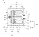
- FIG. 1 is a cross-sectional view of a rotating electric machine according to a first embodiment.
- 3 is a cross-sectional view of a first stator according to the first embodiment.
- FIG. FIG. 4 is a side view of a second load rotor according to the first embodiment. 4 is a diagram for explaining the operation of the rotating electric machine according to the first embodiment;
- FIG. 11 is a cross-sectional view of a rotating electric machine according to a second embodiment.
- FIG. FIG. 11 is a cross-sectional view of a first rotor according to a second embodiment.
- FIG. 11 is a cross-sectional view of a rotating electric machine according to a third embodiment.
- FIG. 11 is a cross-sectional view of a first rotor according to embodiment 3.
- FIG. 11 is a cross-sectional view of a first rotor according to embodiment 3.
- FIG. 11 is a cross-sectional view of a rotating electric machine according to a fourth embodiment.
- FIG. 11 is a cross-sectional view of a second stator according to embodiment 4.
- FIG. 13 is a cross-sectional view of a rotating electric machine according to a fifth embodiment.
- FIG. 13 is a cross-sectional view of a rotating electric machine according to a sixth embodiment.
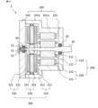
- Fig. 1 is a cross-sectional view of a rotating electric machine according to a first embodiment.
- Fig. 1 is a cross-sectional view in a direction parallel to a rotating shaft, which will be described later.
- the rotating shaft is connected to a load (not shown) on the right side of Fig. 1. Therefore, in Fig. 1, the right side is referred to as the load side, and the left side is referred to as the anti-load side.
- the rotating electric machine 1 of this embodiment includes a first rotary drive unit 200 arranged on the load side and a second rotary drive unit 300 arranged on the counter-load side.
- the first rotary drive unit 200 and the second rotary drive unit 300 are built into one frame 100 and share one rotating shaft 20.
- the rotating shaft 20 is rotatably supported by the load side bearing 30 and the counter-load side bearing 40 relative to the frame 100.
- the load side end of the rotating shaft 20 is extended to the outside of the frame 100 and connected to the load.
- the direction parallel to the rotating shaft 20 is referred to as the axial direction
- the direction perpendicular to the rotating shaft 20 is referred to as the radial direction
- the direction in which the rotating shaft 20 rotates is referred to as the circumferential direction.
- the inner diameter side is the direction approaching the rotating shaft 20 in the radial direction
- the outer diameter side is the direction moving away from the rotating shaft 20 in the radial direction.
- the frame 100 is composed of a cylindrical central frame 101 that covers the first rotary drive unit 200 and the second rotary drive unit 300 on the radial outside, a load side plate 102 that covers the load side end of the central frame 101, and a counter-load side plate 103 that covers the counter-load side end.
- a resolver rotor 51 which is a rotational position sensor that detects the rotational position of the rotating shaft 20, is fastened to the counter-load side end of the rotating shaft 20.
- a resolver stator 52 is fastened to the counter-load side plate 103 and is disposed with a gap between the resolver rotor 51 and the resolver stator 52.
- a resolver cover 53 that covers the resolver rotor 51 and the resolver stator 52 is attached to the counter-load side plate 103.
- the first rotary drive unit 200 is an induction machine and is arranged on the load side within the rotating electric machine 1.
- the first rotary drive unit 200 has a first rotor 210 fastened to the rotating shaft 20 and a first stator 220 fastened to the central frame 101.
- the first rotor 210 and the first stator 220 are arranged with a gap in the radial direction.
- the first rotor 210 is composed of a first rotor core 211 of annular shape fastened to the rotating shaft 20 and a first rotor coil 212.
- the first rotor core 211 has a main body part of an annular shape and 59 teeth protruding from this main body part to the outer diameter side.
- the first rotor coil 212 is a cage-type conductor arranged in the slots, which are the spaces between the teeth.
- FIG. 2 is a cross-sectional view of the first stator according to this embodiment.
- the first stator 220 is composed of a first stator core 221 in a circular ring shape fastened to the central frame 101, and a first stator coil 222.
- the first stator core 221 has a circular ring-shaped main body and 48 teeth protruding from the main body to the inner diameter side.
- the first stator coil 222 is wound around the teeth in a distributed winding manner.
- the first rotary drive unit 200 thus configured is an 8-pole radial gap type squirrel-cage induction machine. Note that the radial gap type is a structure in which a gap exists between the rotor and stator in the radial direction.
- the second rotary drive unit 300 is a permanent magnet synchronous rotating machine, and is arranged on the anti-load side within the rotating electric machine 1.
- the second rotary drive unit 300 has a load side second rotor 310 and an anti-load side second rotor 320 fastened to the rotating shaft 20, and a second stator 330 fastened to the central frame 101.
- the load side second rotor 310 is arranged on the axial load side of the second stator 330 via a gap.
- the anti-load side second rotor 320 is arranged on the axial anti-load side of the second stator 330 via a gap.
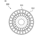
- the load side second rotor 310 is composed of a disk-shaped load side second rotor core 311 fastened to the rotating shaft 20, and a load side second rotor magnet 312.
- the load side second rotor magnet 312 is embedded in the surface of the load side second rotor core 311 that faces the second stator 330.
- the load side second rotor magnets 312 are sector-shaped, and 24 of them are arranged at equal intervals in the circumferential direction, with the north and south poles facing alternately in the axial direction.
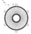
- FIG. 3 is a side view of the load side second rotor 310 according to this embodiment.
- FIG. 3 is a side view of the load side second rotor 310 as seen from the second stator 330 side.
- the load side second rotor 310 has 24 load side second rotor magnets 312 arranged at equal intervals in the circumferential direction on a disk-shaped load side second rotor core 311.
- the anti-load side second rotor 320 is composed of a disk-shaped anti-load side second rotor core 321 fastened to the rotating shaft 20, and an anti-load side second rotor magnet 322.
- the anti-load side second rotor magnet 322 is embedded in the surface of the anti-load side second rotor core 321 facing the second stator 330.
- the anti-load side second rotor magnets 322 are sector-shaped, and 24 of them are arranged at equal intervals in the circumferential direction, with the north poles and south poles alternately facing the axial direction.
- the side of the anti-load side second rotor 320 seen from the second stator 330 side is similar to the side of the load side second rotor 310 shown in FIG. 3.
- the load side second rotor magnet 312 of the load side second rotor 310 and the anti-load side second rotor magnet 322 of the anti-load side second rotor 320 are arranged so that the magnetic poles of the magnets at the same position in the circumferential direction face the second stator 330 with their north and south poles facing each other.
- the second stator 330 is composed of a circular ring-shaped second stator base 331 fastened to the central frame 101, and a second stator coil 332.
- the second stator base 331 has 72 slots formed at equal intervals in the circumferential direction at a mechanical angle of 5 degrees.
- the second stator coil 332 is wound around these 72 slots at a 6-slot pitch.
- the second rotation drive unit 300 thus configured is an axial gap type permanent magnet synchronous rotating machine.
- the axial gap type is a structure in which a gap exists between a disk-shaped rotor and a stator in the axial direction.
- the frame 100, the rotating shaft 20, the second stator 330, and the second stator base 331 are non-magnetic and made of, for example, aluminum, resin, etc. These members are desirably made of resin, which is a non-conductive material, so that eddy current loss due to magnetic flux fluctuation does not occur.
- the first rotor core 211, the first stator core 221, the load side second rotor core 311, and the counter-load side second rotor core 321 are magnetic and made of, for example, laminated electromagnetic steel sheets.
- the first rotor coil 212, the first stator coil 222, and the second stator coil 332 are made by winding a conductor wire made of, for example, copper, aluminum, iron, etc.
- the load side second rotor magnet 312 and the counter-load side second rotor magnet 322 are permanent magnets, for example, rare earth magnets.
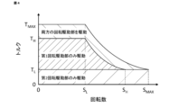
- Fig. 4 is a diagram showing the operation of the rotating electric machine according to this embodiment.
- the horizontal axis is rotation speed
- the vertical axis is torque.
- S MAX is the maximum rotation speed of the rotating electric machine 1
- S H is a threshold value on the high rotation speed side
- S L is a threshold value on the low rotation speed side, with S L ⁇ S H ⁇ S MAX .
- T MAX is the maximum torque of the rotating electric machine 1
- T H is a threshold value on the high torque side
- T L is a threshold value on the low torque side, with T L ⁇ T H ⁇ T MAX .
- the rotating electric machine 1 of this embodiment is driven only by the second rotary drive unit 300 when the torque is from 0 to T L regardless of the rotation speed.
- the rotating electric machine 1 is driven only by the first rotary drive unit 200 when the rotation speed is in the range from 0 to S L and the torque is from T L to T H.
- the rotating electric machine 1 is driven by both the first rotary drive unit 200 and the second rotary drive unit 300 when the rotation speed is in the range from 0 to S L and the torque is from T H to T MAX .
- the rotating electric machine 1 is driven only by the first rotary drive unit 200 in the rotation speed range from S L to S H and the torque range from T L to T H on the constant output curve. Moreover, the rotating electric machine 1 is driven by both the first rotary drive unit 200 and the second rotary drive unit 300 in the rotation speed range from S L to S MAX and the torque range from the constant output curve of T H to the constant output curve of T MAX.
- the torque distribution is such that the second rotational drive unit 300 always outputs torque T L and the first rotational drive unit 200 outputs the remaining required torque.
- T L is the maximum torque that the second rotational drive unit 300 can output
- T H is the maximum torque that the first rotational drive unit 200 can output.
- T MAX T L +T H
- T MAX is the maximum torque that the rotating electric machine 1 can output.
- S L which is a threshold value on the low rotational speed side
- S H which is a threshold value on the high rotational speed side
- S L which is a threshold value on the low rotational speed side
- S H which is a threshold value on the high rotational speed side
- frequent drive switching may occur.
- frequent drive switching can be avoided. For example, when the torque increases and decreases across the border line, frequent drive switching can be avoided by setting the threshold value that is the border line when the torque decreases to 95% of the threshold value that is the border line when the torque increases.
- the rotating electrical machine 1 when the torque is equal to or less than T L , it is driven only by the second rotary drive unit 300, which is an axial gap type permanent magnet synchronous rotating machine, and therefore it is possible to reduce iron loss caused by PWM carrier harmonics that are generated when the second rotary drive unit 300 is inverter driven, thereby improving efficiency in the low torque region.
- the second rotary drive unit 300 has permanent magnets as a field source in the load side second rotor 310 and the anti-load side second rotor 320, but since the second stator base 331 of the second stator 330 is made of a non-magnetic material, no stator iron loss occurs due to the rotating magnetic field generated by the rotor field. This improves the efficiency of the rotating electric machine 1.
- the first rotary drive unit 200 When only the second rotary drive unit 300 is driven, the first rotary drive unit 200 also rotates in conjunction with it. However, since the first rotary drive unit 200 is an induction machine, no electromagnetic loss occurs due to the interlocking rotation.
- the rotating electrical machine 1 is driven only by the first rotary drive unit 200.
- the region where only the first rotary drive unit 200, which is a cage induction machine, is driven is not a low torque region where efficiency is low. Therefore, it is possible to suppress the decrease in efficiency in the low torque region.
- the second rotary drive unit 300 also rotates in conjunction with it.
- the second rotary drive unit 300 is provided with a permanent magnet as a field source
- the second stator base 331 of the second stator 330 is made of a non-magnetic material, so that no stator iron loss occurs due to the rotating magnetic field generated by the rotor field magnet. Therefore, it is possible to improve the efficiency of the rotating electric machine 1.
- the rotating magnetic field generated between the first rotor 210 and the first stator 220 of the first rotary drive unit 200 interlinks with the load side second rotor core 311 of the second rotary drive unit 300.
- the rotating magnetic field generated in the first rotary drive unit 200 rotates at the same rotation speed as the load side second rotor core 311, it does not become an alternating magnetic field in the load side second rotor core 311.
- no iron loss occurs in the load side second rotor core 311. Therefore, even if the axial distance between the first rotary drive unit 200 and the second rotary drive unit 300 is shortened, the efficiency does not decrease. As a result, the rotating electric machine of this embodiment can be prevented from becoming large.
- the load side second rotor core 311 of the second rotary drive unit 300 is disposed closer to the first rotary drive unit 200 than the second stator 330.
- the second rotary drive unit 300 and the first rotary drive unit 200 rotate synchronously. Therefore, the load side second rotor core 311 shields the rotating magnetic field of the first rotary drive unit 200, so that the rotating magnetic field of the first rotary drive unit 200 does not interlink with the second stator 330.
- the rotating electric machine 1 of this embodiment can improve efficiency without increasing its size.
- the second rotary drive unit 300 which has a second stator base 331 made of a non-magnetic material and rotates using the field magnet of a permanent magnet, has high efficiency. In a region driven by both the first rotary drive unit 200 and the second rotary drive unit 300, the highly efficient second rotary drive unit 300 always generates maximum torque, thereby improving the maximum performance of the rotating electric machine 1.
- the second rotary drive unit 300 which is a permanent magnet synchronous rotating machine, is greatly influenced by the rotational position when it comes to control.
- the resolver rotor 51 which is a rotational position sensor, is disposed at the end of the rotating shaft 20 on the anti-load side. Therefore, since the resolver rotor 51 is disposed near the second rotary drive unit 300, it is less affected by the twisting of the rotating shaft 20, and the controllability of the second rotary drive unit 300 can be improved.
- the first rotary drive unit is an eight-pole radial gap type squirrel-cage induction machine.
- the first rotary drive unit is configured as a synchronous reluctance motor.
- FIG. 5 is a cross-sectional view of a rotating electric machine according to this embodiment.
- the configuration of the rotating electric machine according to this embodiment is similar to that of the rotating electric machine according to embodiment 1 shown in FIG. 1, but the configuration of the first rotary drive unit 200 is different from that of the first rotary drive unit according to embodiment 1.
- the first rotor 210 according to this embodiment is composed only of a first rotor core 211 having an annular shape fastened to the rotating shaft 20. This first rotor core 211 has a plurality of slits 213 formed therein that penetrate in the axial direction.
- FIG. 6 is a cross-sectional view of the first rotor according to this embodiment.
- FIG. 6 is a cross-sectional view in a direction perpendicular to the rotation axis.
- the first rotor 210 according to this embodiment has a plurality of slits 213 formed in the first rotor core 211. These slits 213 serve as flux barriers that form salient poles facing the inner diameter side. Eight sets of these flux barriers are formed at equal intervals in the circumferential direction.
- the rotating electric machine 1 according to this embodiment has the first rotary drive unit 200 configured as a synchronous reluctance motor.
- the rotating electric machine 1 of this embodiment is driven in the same way as the rotating electric machine of embodiment 1. Therefore, like the rotating electric machine of embodiment 1, it is possible to satisfy the maximum performance required without increasing the size and to improve efficiency in the low torque range.
- the first rotary drive unit is an eight-pole radial gap type squirrel-cage induction machine.
- the first rotary drive unit is configured as a switched reluctance motor.
- FIG. 7 is a cross-sectional view of a rotating electric machine according to this embodiment.
- the configuration of the rotating electric machine according to this embodiment is similar to the configuration of the rotating electric machine according to embodiment 1 shown in FIG. 1, but the configuration of the first rotary drive unit 200 is different from the configuration of the first rotary drive unit according to embodiment 1.
- the first stator 220 in the rotating electric machine of this embodiment is composed of a first stator core 221 in a circular ring shape fastened to the central frame 101, and a first stator coil 222.
- the first stator core 221 has a circular ring-shaped main body and 12 teeth protruding from this main body to the inner diameter side.
- the first stator coil 222 is wound around the teeth in a concentrated winding manner.
- the first rotor 210 in this embodiment is composed only of a first rotor core 211 fastened to the rotating shaft 20.
- This first rotor core 211 is composed of a ring-shaped main body and eight protrusions 214 protruding from the main body to the outer diameter side.
- FIG. 8 is a cross-sectional view of the first rotor according to this embodiment.
- FIG. 8 is a cross-sectional view in a direction perpendicular to the rotation axis.
- the first rotor 210 according to this embodiment has eight protrusions 214 protruding from the annular main body of the first rotor core 211 toward the outer diameter side.
- the eight protrusions 214 are formed at equal intervals in the circumferential direction.
- the rotating electric machine 1 according to this embodiment has the first rotary drive unit 200 configured as a switched reluctance motor.
- the rotating electric machine 1 of this embodiment is driven in the same way as the rotating electric machine of embodiment 1. Therefore, like the rotating electric machine of embodiment 1, it is possible to satisfy the maximum performance required without increasing the size and to improve efficiency in the low torque range.
- the second rotary drive unit is an axial gap type permanent magnet synchronous rotating machine having no magnetic body in the stator.
- the second rotary drive unit has a stator made of a magnetic body.
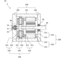
- FIG. 9 is a cross-sectional view of a rotating electric machine according to this embodiment.
- the configuration of the rotating electric machine according to this embodiment is similar to the configuration of the rotating electric machine according to embodiment 1 shown in FIG. 1, but the configuration of the second rotary drive unit 300 is different from the configuration of the second rotary drive unit according to embodiment 1.
- FIG. 10 is a cross-sectional view of the second stator according to this embodiment.
- the second stator 330 in the rotating electric machine of this embodiment is composed of a second stator core 333 having a circular ring shape fastened to the central frame 101, and a second stator coil 332.
- the second stator core 333 is composed of a magnetic material.
- This second stator core 333 has 48 teeth through which magnetic flux passes in the axial direction, and a teeth connection portion that connects these 48 teeth at the center in the axial direction.
- the circumferential width of the teeth connection portion is smaller than the circumferential width of the teeth.
- the second stator coil 332 is wound around the teeth.
- the second rotary drive unit 300 has a second stator core 333 made of a magnetic material, so iron loss occurs due to PWM carrier harmonics that are generated when the second rotary drive unit 300 is inverter driven.
- the second rotary drive unit 300 also rotates in conjunction with it, and stator iron loss occurs due to the rotating magnetic field. Therefore, the rotating electric machine of this embodiment is less efficient than the rotating electric machine of embodiment 1.
- the second rotary drive unit 300 has a second stator core 333 made of a magnetic material, so the torque of the second rotary drive unit 300 can be further improved.
- the teeth connection parts that connect the teeth of the second stator core 333 in the circumferential direction are small and do not function as a yoke, so there is almost no iron loss due to the magnetic flux passing through the second stator core 333 in the circumferential direction. Therefore, there is less decrease in efficiency compared to general rotating electric machines.
- the load side second rotor core 311 of the second rotary drive unit 300 is disposed closer to the first rotary drive unit 200 than the second stator core 333.
- the second rotary drive unit 300 and the first rotary drive unit 200 rotate synchronously. Therefore, the load side second rotor core 311 shields the rotating magnetic field of the first rotary drive unit 200, so that the rotating magnetic field of the first rotary drive unit 200 does not interlink with the second stator core 333.
- the rotating electric machine 1 of this embodiment can improve efficiency without increasing its size.
- the rotating electric machine according to the fifth embodiment is the rotating electric machine according to the fourth embodiment, except that the anti-load side second rotor is removed.
- FIG. 11 is a cross-sectional view of a rotating electric machine according to this embodiment.
- the configuration of the rotating electric machine according to this embodiment is similar to that of the rotating electric machine according to embodiment 4 shown in FIG. 9, but the configuration of the second rotary drive unit 300 is different from that of the second rotary drive unit according to embodiment 4.
- the second rotary drive unit 300 according to this embodiment has a load side second rotor 310 fastened to the rotating shaft 20 and a second stator 330 fastened to the central frame 101.
- the load side second rotor 310 is arranged on the axial load side of the second stator 330 via a gap.
- the second stator 330 in the rotating electric machine of this embodiment is composed of a second stator core 333 in a circular ring shape fastened to the central frame 101, and a second stator coil 332.
- the second stator core 333 is composed of a magnetic material.
- This second stator core 333 has 48 teeth through which magnetic flux passes in the axial direction, and a teeth connection portion that connects these 48 teeth at the anti-load side end in the axial direction.
- the circumferential width of the teeth connection portion is larger than the circumferential width of the teeth.
- the second stator coil 332 is wound around the teeth.
- the load side second rotor core 311 is arranged closer to the first rotary drive unit 200 than the second stator core 333.
- the second rotary drive unit 300 and the first rotary drive unit 200 rotate synchronously. Therefore, the load side second rotor core 311 shields the rotating magnetic field of the first rotary drive unit 200, so that the rotating magnetic field of the first rotary drive unit 200 does not interlink with the second stator core 333.
- the rotating electric machine 1 of this embodiment can improve efficiency without increasing the size, similar to embodiment 4.
- the second rotary drive unit does not have a second rotor on the non-load side, so the number of parts is reduced and the size can be reduced compared to the rotating electric machine of embodiment 4.
- Fig. 12 is a cross-sectional view of a rotating electric machine according to the sixth embodiment.
- the configuration of the rotating electric machine of the present embodiment is similar to the configuration of the rotating electric machine of the first embodiment shown in Fig. 1, but the outer diameter of the second rotary drive unit 300 is larger than the outer diameter of the first rotary drive unit 200.
- the frame 100 is composed of a cylindrical load side central frame 101a that covers the first rotation drive unit 200 on the radial outside, a cylindrical anti-load side central frame 101b that covers the second rotation drive unit 300 on the radial outside, a load side plate 102 that covers the load side end of the load side central frame 101a, and an anti-load side plate 103 that covers the anti-load side end of the anti-load side central frame 101b.
- the outer diameter of the counter-load side central frame 101b is larger than the outer diameter of the load side central frame 101a. Therefore, the outer diameter of the second rotation drive unit 300 arranged inside the counter-load side central frame 101b can be made larger than the outer diameter of the first rotation drive unit 200 arranged inside the load side central frame 101a.
- the torque of the second rotary drive unit 300 can be improved, thereby improving the torque of the entire rotating electric machine.
- the configurations of the number of poles and the number of slots of the first and second rotary drive units are exemplified, but the present invention is not limited to these configurations.
- the first rotary drive unit has 8 poles and 48 slots
- the second rotary drive unit has 8 poles and 48 slots
- the first rotary drive unit may have 6 poles and 36 slots
- the second rotary drive unit may have 12 poles and 72 slots.
- 1 rotating electric machine 20 rotating shaft, 30 load side bearing, 40 counter load side bearing, 51 resolver rotor, 52 resolver stator, 53 resolver cover, 100 frame, 101 central frame, 101a load side central frame, 101b counter load side central frame, 102 load side plate, 103 counter load side plate, 200 first rotating drive unit, 210 first rotor, 211 first rotor core, 212 first rotor coil, 21 3 slit, 214 protrusion, 220 first stator, 221 first stator core, 222 first stator coil, 300 second rotary drive unit, 310 load side second rotor, 311 load side second rotor core, 312 load side second rotor magnet, 320 anti-load side second rotor, 321 anti-load side second rotor core, 322 anti-load side second rotor magnet, 330 second stator, 331 second stator base, 332 second stator coil, 333 second stator core.
Landscapes
- Engineering & Computer Science (AREA)
- Power Engineering (AREA)
- Permanent Magnet Type Synchronous Machine (AREA)
Abstract
La présente invention concerne une machine électrique tournante qui répond à une exigence de performance maximale et améliore le rendement dans une zone de faible couple sans augmentation de la taille. Une machine électrique tournante (1) comprend une première unité d'entraînement rotatif (200) et une seconde unité d'entraînement rotatif (300) qui partagent un arbre rotatif (20). La première unité d'entraînement rotatif est une unité d'entraînement rotatif de type à entrefer radial qui comprend un premier stator (220) et un premier rotor (210), et la seconde unité d'entraînement rotatif est une unité d'entraînement rotatif de type à entrefer axial qui comprend un second stator (330) et un second rotor (310) qui comprend un second noyau de rotor (311) et un second aimant de rotor (312) et qui est fixé à l'arbre rotatif du côté de la première unité d'entraînement rotatif du second stator au niveau d'un entrefer dans la direction axiale.
Priority Applications (3)
| Application Number | Priority Date | Filing Date | Title |
|---|---|---|---|
| CN202380101525.1A CN121713365A (zh) | 2023-08-21 | 2023-08-21 | 旋转电机及旋转电机的驱动方法 |
| PCT/JP2023/029997 WO2025041224A1 (fr) | 2023-08-21 | 2023-08-21 | Machine électrique tournante et procédé d'entraînement de machine électrique tournante |
| JP2023579160A JP7562024B1 (ja) | 2023-08-21 | 2023-08-21 | 回転電機および回転電機の駆動方法 |
Applications Claiming Priority (1)
| Application Number | Priority Date | Filing Date | Title |
|---|---|---|---|
| PCT/JP2023/029997 WO2025041224A1 (fr) | 2023-08-21 | 2023-08-21 | Machine électrique tournante et procédé d'entraînement de machine électrique tournante |
Publications (1)
| Publication Number | Publication Date |
|---|---|
| WO2025041224A1 true WO2025041224A1 (fr) | 2025-02-27 |
Family
ID=92909824
Family Applications (1)
| Application Number | Title | Priority Date | Filing Date |
|---|---|---|---|
| PCT/JP2023/029997 Pending WO2025041224A1 (fr) | 2023-08-21 | 2023-08-21 | Machine électrique tournante et procédé d'entraînement de machine électrique tournante |
Country Status (3)
| Country | Link |
|---|---|
| JP (1) | JP7562024B1 (fr) |
| CN (1) | CN121713365A (fr) |
| WO (1) | WO2025041224A1 (fr) |
Citations (5)
| Publication number | Priority date | Publication date | Assignee | Title |
|---|---|---|---|---|
| JPH0662597A (ja) * | 1992-06-10 | 1994-03-04 | Fuji Electric Co Ltd | 交流可変速駆動装置 |
| JP2012178924A (ja) * | 2011-02-25 | 2012-09-13 | Aisan Ind Co Ltd | ステッピングモータ、egrバルブ |
| JP2016163436A (ja) * | 2015-03-02 | 2016-09-05 | トヨタ自動車株式会社 | 電動モータ |
| WO2019202768A1 (fr) * | 2018-04-18 | 2019-10-24 | 株式会社日立産機システム | Machine dynamo-électrique à entrefer axial |
| JP2020501484A (ja) * | 2016-11-18 | 2020-01-16 | ジン−ジン エレクトリック テクノロジーズ カンパニー リミテッド | 同軸マルチモータ駆動システム、及び、同軸マルチモータ駆動システムが設けられた車両 |
Family Cites Families (1)
| Publication number | Priority date | Publication date | Assignee | Title |
|---|---|---|---|---|
| CN115398777A (zh) * | 2020-05-08 | 2022-11-25 | 住友电气工业株式会社 | 铁芯片、定子铁芯、定子、旋转电机及铁芯片的制造方法 |
-
2023
- 2023-08-21 WO PCT/JP2023/029997 patent/WO2025041224A1/fr active Pending
- 2023-08-21 CN CN202380101525.1A patent/CN121713365A/zh active Pending
- 2023-08-21 JP JP2023579160A patent/JP7562024B1/ja active Active
Patent Citations (5)
| Publication number | Priority date | Publication date | Assignee | Title |
|---|---|---|---|---|
| JPH0662597A (ja) * | 1992-06-10 | 1994-03-04 | Fuji Electric Co Ltd | 交流可変速駆動装置 |
| JP2012178924A (ja) * | 2011-02-25 | 2012-09-13 | Aisan Ind Co Ltd | ステッピングモータ、egrバルブ |
| JP2016163436A (ja) * | 2015-03-02 | 2016-09-05 | トヨタ自動車株式会社 | 電動モータ |
| JP2020501484A (ja) * | 2016-11-18 | 2020-01-16 | ジン−ジン エレクトリック テクノロジーズ カンパニー リミテッド | 同軸マルチモータ駆動システム、及び、同軸マルチモータ駆動システムが設けられた車両 |
| WO2019202768A1 (fr) * | 2018-04-18 | 2019-10-24 | 株式会社日立産機システム | Machine dynamo-électrique à entrefer axial |
Also Published As
| Publication number | Publication date |
|---|---|
| JPWO2025041224A1 (fr) | 2025-02-27 |
| JP7562024B1 (ja) | 2024-10-04 |
| CN121713365A (zh) | 2026-03-20 |
Similar Documents
| Publication | Publication Date | Title |
|---|---|---|
| JP4670871B2 (ja) | モータ | |
| US6217298B1 (en) | Electrodynamic transmission and a centrifugal pump with a transmission of this kind | |
| EP2448089A1 (fr) | Moteur axial | |
| EP0813287B1 (fr) | Moteur à réluctance commuté | |
| WO2015097767A1 (fr) | Machine électrique rotative de type à aimant permanent | |
| US20230046567A1 (en) | Magnetic geared rotary electric machine | |
| US10637305B2 (en) | Double stator-type rotary machine | |
| WO2021099318A1 (fr) | Rotor de machine synchrone | |
| JPWO2021131071A1 (ja) | ハイブリッド界磁式ダブルギャップ同期機および駆動システム | |
| JP2021129443A (ja) | モータ | |
| US10483813B2 (en) | Rotor having flux filtering function and synchronous motor comprising same | |
| US20220200375A1 (en) | Four-pole synchronous reluctance motor | |
| JP7270806B1 (ja) | 回転電機 | |
| JP7615913B2 (ja) | 回転電機 | |
| JP7562024B1 (ja) | 回転電機および回転電機の駆動方法 | |
| US10833545B2 (en) | Rotor for hybrid homopolar machine | |
| JP2019017208A (ja) | 回転子及び永久磁石式回転電機 | |
| EP3499686A2 (fr) | Machine électrique à réluctance commutée comprenant des barrières de flux polaires | |
| JP7308163B2 (ja) | モータ | |
| JP2012080616A (ja) | 可変磁束モータ | |
| JP2017060274A (ja) | 永久磁石回転電機 | |
| JP7666109B2 (ja) | 回転電機 | |
| US12519355B2 (en) | Rotor | |
| EP4329152A1 (fr) | Rotor | |
| EP4468565A1 (fr) | Machine électrique rotative |
Legal Events
| Date | Code | Title | Description |
|---|---|---|---|
| ENP | Entry into the national phase |
Ref document number: 2023579160 Country of ref document: JP Kind code of ref document: A |
|
| WWE | Wipo information: entry into national phase |
Ref document number: 2023579160 Country of ref document: JP |
|
| 121 | Ep: the epo has been informed by wipo that ep was designated in this application |
Ref document number: 23949685 Country of ref document: EP Kind code of ref document: A1 |
|
| NENP | Non-entry into the national phase |
Ref country code: DE |