WO2025041216A1 - Compresseur de gaz, procédé de gestion de maintenance de composant associé, et système de gestion de maintenance de composant - Google Patents
Compresseur de gaz, procédé de gestion de maintenance de composant associé, et système de gestion de maintenance de composant Download PDFInfo
- Publication number
- WO2025041216A1 WO2025041216A1 PCT/JP2023/029943 JP2023029943W WO2025041216A1 WO 2025041216 A1 WO2025041216 A1 WO 2025041216A1 JP 2023029943 W JP2023029943 W JP 2023029943W WO 2025041216 A1 WO2025041216 A1 WO 2025041216A1
- Authority
- WO
- WIPO (PCT)
- Prior art keywords
- maintenance
- parts
- gas compressor
- display unit
- maintenance management
- Prior art date
- Legal status (The legal status is an assumption and is not a legal conclusion. Google has not performed a legal analysis and makes no representation as to the accuracy of the status listed.)
- Pending
Links
Images


Classifications
-
- F—MECHANICAL ENGINEERING; LIGHTING; HEATING; WEAPONS; BLASTING
- F04—POSITIVE - DISPLACEMENT MACHINES FOR LIQUIDS; PUMPS FOR LIQUIDS OR ELASTIC FLUIDS
- F04B—POSITIVE-DISPLACEMENT MACHINES FOR LIQUIDS; PUMPS
- F04B49/00—Control, e.g. of pump delivery, or pump pressure of, or safety measures for, machines, pumps, or pumping installations, not otherwise provided for, or of interest apart from, groups F04B1/00 - F04B47/00
- F04B49/10—Other safety measures
Definitions
- the present invention relates to a gas compressor, a parts maintenance management method, and a parts maintenance management system.
- TBM Time Based Maintenance
- CBM Condition Based Maintenance
- TBM parts Maintenance for parts subject to TBM (hereafter referred to as “TBM parts”) is generally carried out at the same time, once every year to once every few years.
- CBM parts maintenance for parts subject to CBM (hereafter referred to as “CBM parts”) is carried out depending on the condition of the parts, but from the perspective of maintenance costs, it is desirable to carry out maintenance at the same time as maintenance for TBM parts.
- Patent Document 1 describes a technique for requesting maintenance of the part based on the arrival of a first maintenance interval that is not related to the actual utilization of the device, determining whether a second maintenance interval that is linked to the actual utilization of the device has been reached based on the arrival of the first maintenance interval, and temporarily prohibiting the maintenance request and extending the first maintenance interval if the second maintenance interval has not been reached.
- the parts maintenance management system described in Patent Document 1 can appropriately extend the first maintenance interval by referring to a first maintenance interval that is set regardless of the actual device operation and a second maintenance interval that is set based on the actual device operation.
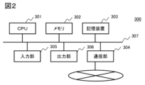
- the CPU 201 is a central processing unit, and implements necessary functions by executing programs stored in the memory 302 (or storage device 303).
- the memory 302 is a main storage device used by the CPU 201 when executing processes, and is composed of volatile storage elements such as RAM (Random Access Memory).
- the storage device 303 is an auxiliary storage device for storing input data provided to the CPU 201 and output data output from the CPU 201, and is composed of non-volatile storage elements such as an HDD (Hard Disk Drive) or SSD (Solid State Drive).
- FIG. 4 is a diagram showing an example of a message displayed on the display unit 123 of the first embodiment.
- the MSG 127 displays, for example, the part name "Intercooler”, the remaining operating time until maintenance "12000 hours", and a work instruction to the user to extend the maintenance period "Clean or improve the surrounding environment".
- the work instruction to the user is preregistered in the control device 119 for each part.
- the user can decide to postpone the maintenance one year after the base date and postpone it to two years after the base date. This will reduce the number of maintenances and cut maintenance costs.
- the calculation processing and the display corresponding to the processing are executed by the control device 119 and the display unit 123.
- the device it is also possible to configure the device to be communicatively connected to the network cloud 125 via the antenna 124, and to execute the calculation processing and instructions for the display content on the server 300 (FIG. 2) on the network cloud 125, and display the information on the display unit 123, or to display the information on the display unit of the server 300 (FIG. 2).
- control device 119 transmits the second stage suction temperature T S2 detected by the temperature detector 122 to the server 300 via the antenna 124.
- the CPU 201 performs calculations similar to those of the control device 119 described above, and displays the MSG 127 on the display unit 123.
- the CPU 201 may also display the MSG 127 on the display unit of the server 300.
- control device 119 estimates the maintenance timing of the intercooler 104 based on the second stage suction temperature T S2 detected by the temperature detector 122 and displays the remaining operating time until maintenance on the display unit 123, so that the maintenance timing of the CBM parts of the gas compressor can be estimated and managed.
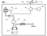
- An oil separation tank 204 that separates the gas-liquid mixture of compressed air and oil is provided on the discharge side of the compressor body 201, and an aftercooler 205 for cooling the compressed air is provided downstream of the oil separation tank 204.
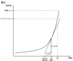
- FIG. 6 is a graph showing an example of the relationship between the wear level F of a part and the period t in Example 2.
- the part to be maintained in this example is the intake filter 202.
- the suction filter 202 When the suction filter 202 is a TBM part, it usually requires maintenance once a year, but as a CBM part, it is possible to estimate the maintenance timing based on the wear level ⁇ F of the suction filter 202 over a period ⁇ t.
- the wear level of the suction filter 202 depends mainly on the clogging of the suction filter.
- the degree of wear ⁇ F of the suction filter 202 can be calculated from a decrease in the suction pressure P S , which is the pressure inside the suction filter 202, detected by the pressure detector 206.
- the method of calculating the degree of wear ⁇ F of the suction filter 202 will be described below.
- a method for estimating the maintenance timing of the suction filter 202 from the calculation results of the control device 207 will be described with reference to the graph in Figure 6.
- the vertical axis of the graph indicates the wear level F
- the horizontal axis indicates the period t
- the solid line indicates ⁇ F/ ⁇ t.
- the wear level at which the suction filter 202 requires maintenance is 1, and the wear level at which the suction filter 202 is damaged is 1.2.
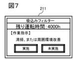
- FIG. 7 is a diagram showing an example of a message displayed on the display unit 208 of the second embodiment.
- the MSG 211 displays, for example, the part name "suction filter", the remaining operation time until maintenance "4000 hours", and a work instruction to the user to extend the maintenance period "clean or improve the surrounding environment".
- the work instruction to the user is registered in advance in the control device 207 for each part.
- the user can determine that maintenance is necessary without waiting for the maintenance scheduled one year after the reference date. This allows maintenance to be performed at an appropriate time depending on the condition of the parts.
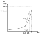
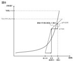
- FIG. 8 is a graph showing an example of the relationship between the wear rate F of a part and the period t in Example 2.
- the reference date is six months after the date of installation of the oil-lubricated screw compressor 200, and six months have passed since the reference date.
- the method of estimating the maintenance timing of the suction filter 202 from the calculation results of the control device 207 will be described with reference to the graph in Figure 8.
- the vertical axis of the graph indicates the wear level F
- the horizontal axis indicates the period t
- the solid line indicates ⁇ F/ ⁇ t.
- the wear level at which the suction filter 202 requires maintenance is 1, and the wear level at which the suction filter 202 is damaged is 1.2.
- the relationship between the wear rate ⁇ F calculated by the control device 207 and the period ⁇ t is shown by a dotted line. From the dotted line in Figure 8, it is estimated that the wear rate F will reach 1 one year after the installation date.
- the control device 207 calculates the remaining operating time until maintenance based on the graph in Figure 8, and displays a message on the display unit 208.
- FIG. 9 is a diagram showing an example of a message displayed on the display unit 208 of the second embodiment.
- the MSG 212 displays, for example, the part name "suction filter", the remaining operation time until maintenance "8000 hours", and a work instruction to the user to extend the maintenance period "clean or improve the surrounding environment".
- the work instruction to the user is registered in advance in the control device 207 for each part.
- the user can determine that regular maintenance should be performed one year after the installation date. This reduces the number of maintenance sessions and cuts maintenance costs.
- control device 207 transmits the suction pressure PS detected by the pressure detector 206 to the server 300 via the antenna 209.
- the CPU 201 performs calculations similar to those of the control device 207 described above, and displays a MSG 211 on the display unit 208.
- the CPU 201 may also display the MSG 211 on the display unit of the server 300.
- the control device 207 also displays instructions to the user on the display unit 208 to extend the maintenance interval, so that the user can carry out the work, thereby reducing the number of maintenance operations and lowering maintenance costs.
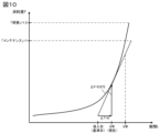
- FIG. 10 is a graph showing an example of the relationship between the wear level F of a part and the period t in Example 3.
- the part to be maintained in this example is an electrolytic capacitor built into the control device 207.
- the degree of wear ⁇ F of the electrolytic capacitor can be calculated from the time tE that electricity is passed through the electrolytic capacitor, which is recorded in the control device 207.
- the method for calculating the degree of wear ⁇ F of the electrolytic capacitor is shown below.
- the method of estimating the maintenance timing of the electrolytic capacitor from the calculation results of the control device 207 will be explained with reference to the graph in Figure 10.
- the vertical axis of the graph indicates the degree of wear F
- the horizontal axis indicates the period t
- the solid line indicates ⁇ F/ ⁇ t.
- the degree of wear at which the electrolytic capacitor requires maintenance is 1, and the degree of wear at which the electrolytic capacitor is damaged is 1.2.
- the relationship between the wear rate ⁇ F calculated by the control device 207 and the period ⁇ t is shown by a dotted line. From the dotted line in Figure 10, it is estimated that the wear rate F will reach 1 after 9 years from the reference date.
- the control device 207 calculates the remaining operating time until maintenance based on the graph in Figure 10, and displays a message on the display unit 208.
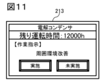
- FIG. 11 is a diagram showing an example of a message displayed on the display unit 208 of the third embodiment.
- the MSG 213 displays, for example, the part name "electrolytic capacitor", the remaining operating time until maintenance "12000 hours", and a work instruction to the user to extend the maintenance period "Improve the surrounding environment".
- the work instruction to the user is registered in advance in the control device 207 for each part.
- the user can decide to postpone the maintenance eight years from the base date and postpone it to nine years later. This will reduce the number of maintenances and cut maintenance costs.
- control device 207 estimates the maintenance timing of the electrolytic capacitor based on the current flow time tE of the electrolytic capacitor and displays the remaining operating time until maintenance on the display unit 208, so that the maintenance timing of the CBM parts of the gas compressor can be estimated and managed.
- the present invention is not limited to the above-described embodiments, but includes various modified examples.
- the above-described embodiments have been described in detail to clearly explain the present invention, and are not necessarily limited to those having all of the configurations described. It is also possible to replace part of the configuration of one embodiment with the configuration of another embodiment, and it is also possible to add the configuration of another embodiment to the configuration of one embodiment. It is also possible to add, delete, or replace part of the configuration of each embodiment with other configurations.
- 100...oil-free screw compressor 101...low-pressure stage compressor main body, 102...high-pressure stage compressor main body, 103...filter, 103A...suction port, 104...intercooler, 105...air piping, 106...air piping, 107...check valve, 108...aftercooler, 109...air piping, 110...low-pressure stage air release piping, 111...low-pressure stage air release piping, 112...low-pressure stage two-way air release valve, 113...low-pressure stage two-way air release valve, 114...high-pressure stage air release piping, 115...high-pressure stage air release piping, 116...high-pressure stage two-way air release valve, 117...high-pressure stage two-way air release valve, 118...pressure detection 119...control device, 120...discharge air piping, 121...pressure detector, 122...temperature detector, 123...display unit, 124...antenna, 125...network cloud, 126...suction throttle valve, 127...
Landscapes
- Engineering & Computer Science (AREA)
- Mechanical Engineering (AREA)
- General Engineering & Computer Science (AREA)
- Compressors, Vaccum Pumps And Other Relevant Systems (AREA)
Abstract
L'invention concerne une technologie qui permet d'estimer et de gérer des temps de maintenance de composants CBM de compresseur de gaz. Un compresseur à vis sans huile (100) comprend : un détecteur de température (122) qui mesure une température d'aspiration de second phase TS2 constituant la température de l'air évacué par un refroidisseur intermédiaire (104) ; un dispositif de commande (119) qui estime, en fonction de la température d'aspiration de second phase TS2, un temps de maintenance du refroidisseur intermédiaire (104) ; et une unité d'affichage (123). Le dispositif de commande (119) affiche, sur l'unité d'affichage (123), un temps de fonctionnement restant jusqu'à la maintenance.
Priority Applications (2)
| Application Number | Priority Date | Filing Date | Title |
|---|---|---|---|
| PCT/JP2023/029943 WO2025041216A1 (fr) | 2023-08-21 | 2023-08-21 | Compresseur de gaz, procédé de gestion de maintenance de composant associé, et système de gestion de maintenance de composant |
| JP2025541178A JPWO2025041216A1 (fr) | 2023-08-21 | 2023-08-21 |
Applications Claiming Priority (1)
| Application Number | Priority Date | Filing Date | Title |
|---|---|---|---|
| PCT/JP2023/029943 WO2025041216A1 (fr) | 2023-08-21 | 2023-08-21 | Compresseur de gaz, procédé de gestion de maintenance de composant associé, et système de gestion de maintenance de composant |
Publications (1)
| Publication Number | Publication Date |
|---|---|
| WO2025041216A1 true WO2025041216A1 (fr) | 2025-02-27 |
Family
ID=94731701
Family Applications (1)
| Application Number | Title | Priority Date | Filing Date |
|---|---|---|---|
| PCT/JP2023/029943 Pending WO2025041216A1 (fr) | 2023-08-21 | 2023-08-21 | Compresseur de gaz, procédé de gestion de maintenance de composant associé, et système de gestion de maintenance de composant |
Country Status (2)
| Country | Link |
|---|---|
| JP (1) | JPWO2025041216A1 (fr) |
| WO (1) | WO2025041216A1 (fr) |
Citations (2)
| Publication number | Priority date | Publication date | Assignee | Title |
|---|---|---|---|---|
| JP2003091313A (ja) * | 2001-09-17 | 2003-03-28 | Hitachi Ltd | 圧縮機の遠隔監視システム |
| WO2020066629A1 (fr) * | 2018-09-28 | 2020-04-02 | 株式会社日立産機システム | Compresseur de gaz |
-
2023
- 2023-08-21 WO PCT/JP2023/029943 patent/WO2025041216A1/fr active Pending
- 2023-08-21 JP JP2025541178A patent/JPWO2025041216A1/ja active Pending
Patent Citations (2)
| Publication number | Priority date | Publication date | Assignee | Title |
|---|---|---|---|---|
| JP2003091313A (ja) * | 2001-09-17 | 2003-03-28 | Hitachi Ltd | 圧縮機の遠隔監視システム |
| WO2020066629A1 (fr) * | 2018-09-28 | 2020-04-02 | 株式会社日立産機システム | Compresseur de gaz |
Also Published As
| Publication number | Publication date |
|---|---|
| JPWO2025041216A1 (fr) | 2025-02-27 |
Similar Documents
| Publication | Publication Date | Title |
|---|---|---|
| US10401879B2 (en) | Topological connectivity and relative distances from temporal sensor measurements of physical delivery system | |
| CN112005069B (zh) | 冷冻干燥处理和装备健康状况监测 | |
| CN103793752B (zh) | 一种基于退化建模的设备失效次数预测方法 | |
| EP3598258B1 (fr) | Dispositif d'évaluation de risque, système d'évaluation de risque, procédé d'évaluation de risque, et programme d'évaluation de risque | |
| US9652728B2 (en) | Methods and systems for generating a business process control chart for monitoring building processes | |
| US20110106747A1 (en) | Turbine life assessment and inspection system and methods | |
| CN114353854A (zh) | 用于在线定位异常传感器的方法、设备和介质 | |
| CN109344983A (zh) | 故障检测方法、装置及计算机可读存储介质 | |
| US20140074867A1 (en) | Methods and systems for evaluating the performance of building processes | |
| WO2017077970A1 (fr) | Système de détermination de pompe à vide et pompe à vide | |
| KR102693299B1 (ko) | 청정도 자동 제어 파티클 카운터 및 모니터링 시스템 | |
| WO2025041216A1 (fr) | Compresseur de gaz, procédé de gestion de maintenance de composant associé, et système de gestion de maintenance de composant | |
| US10942508B2 (en) | Risk assessment device, risk assessment system, risk assessment method, risk assessment program, and data structure | |
| US20090120111A1 (en) | Remote Diagnostics and Prognostics for Refrigerant Systems | |
| CN115307669A (zh) | 用于检测被测系统的异常传感器的方法、设备和介质 | |
| CN104160152A (zh) | 空气压缩机的监视系统 | |
| CN118959401B (zh) | 一种电液比例伺服阀突发性故障的实时诊断方法、设备、介质及产品 | |
| US20240151230A1 (en) | Method for detecting and monitoring condensate in an oil system of an oil-injected compressor or vacuum pump | |
| JP2003131726A (ja) | エネルギ消費量監視方法及び監視システム | |
| CN117786352A (zh) | 滤清器滤芯寿命预测方法及设备 | |
| CN109766243A (zh) | 一种基于幂函数的多核主机性能监控方法 | |
| JP6482742B1 (ja) | リスク評価装置、リスク評価システム、リスク評価方法、及び、リスク評価プログラム | |
| US20130124256A1 (en) | Method and system for monitoring plant assets | |
| TWI854848B (zh) | 監控裝置、監控方法及其電腦程式產品 | |
| WO2025120929A1 (fr) | Dispositif de diagnostic d'état de dispositif et procédé de diagnostic d'état de dispositif |
Legal Events
| Date | Code | Title | Description |
|---|---|---|---|
| 121 | Ep: the epo has been informed by wipo that ep was designated in this application |
Ref document number: 23949677 Country of ref document: EP Kind code of ref document: A1 |
|
| ENP | Entry into the national phase |
Ref document number: 2025541178 Country of ref document: JP Kind code of ref document: A |
|
| WWE | Wipo information: entry into national phase |
Ref document number: 2025541178 Country of ref document: JP |
|
| NENP | Non-entry into the national phase |
Ref country code: DE |