WO2025041216A1 - 気体圧縮機、及びその部品保守管理方法、並びに部品保守管理システム - Google Patents
気体圧縮機、及びその部品保守管理方法、並びに部品保守管理システム Download PDFInfo
- Publication number
- WO2025041216A1 WO2025041216A1 PCT/JP2023/029943 JP2023029943W WO2025041216A1 WO 2025041216 A1 WO2025041216 A1 WO 2025041216A1 JP 2023029943 W JP2023029943 W JP 2023029943W WO 2025041216 A1 WO2025041216 A1 WO 2025041216A1
- Authority
- WO
- WIPO (PCT)
- Prior art keywords
- maintenance
- parts
- gas compressor
- display unit
- maintenance management
- Prior art date
- Legal status (The legal status is an assumption and is not a legal conclusion. Google has not performed a legal analysis and makes no representation as to the accuracy of the status listed.)
- Pending
Links
Images


Classifications
-
- F—MECHANICAL ENGINEERING; LIGHTING; HEATING; WEAPONS; BLASTING
- F04—POSITIVE - DISPLACEMENT MACHINES FOR LIQUIDS; PUMPS FOR LIQUIDS OR ELASTIC FLUIDS
- F04B—POSITIVE-DISPLACEMENT MACHINES FOR LIQUIDS; PUMPS
- F04B49/00—Control, e.g. of pump delivery, or pump pressure of, or safety measures for, machines, pumps, or pumping installations, not otherwise provided for, or of interest apart from, groups F04B1/00 - F04B47/00
- F04B49/10—Other safety measures
Definitions
- the present invention relates to a gas compressor, a parts maintenance management method, and a parts maintenance management system.
- TBM Time Based Maintenance
- CBM Condition Based Maintenance
- TBM parts Maintenance for parts subject to TBM (hereafter referred to as “TBM parts”) is generally carried out at the same time, once every year to once every few years.
- CBM parts maintenance for parts subject to CBM (hereafter referred to as “CBM parts”) is carried out depending on the condition of the parts, but from the perspective of maintenance costs, it is desirable to carry out maintenance at the same time as maintenance for TBM parts.
- Patent Document 1 describes a technique for requesting maintenance of the part based on the arrival of a first maintenance interval that is not related to the actual utilization of the device, determining whether a second maintenance interval that is linked to the actual utilization of the device has been reached based on the arrival of the first maintenance interval, and temporarily prohibiting the maintenance request and extending the first maintenance interval if the second maintenance interval has not been reached.
- the parts maintenance management system described in Patent Document 1 can appropriately extend the first maintenance interval by referring to a first maintenance interval that is set regardless of the actual device operation and a second maintenance interval that is set based on the actual device operation.
- the CPU 201 is a central processing unit, and implements necessary functions by executing programs stored in the memory 302 (or storage device 303).
- the memory 302 is a main storage device used by the CPU 201 when executing processes, and is composed of volatile storage elements such as RAM (Random Access Memory).
- the storage device 303 is an auxiliary storage device for storing input data provided to the CPU 201 and output data output from the CPU 201, and is composed of non-volatile storage elements such as an HDD (Hard Disk Drive) or SSD (Solid State Drive).
- FIG. 4 is a diagram showing an example of a message displayed on the display unit 123 of the first embodiment.
- the MSG 127 displays, for example, the part name "Intercooler”, the remaining operating time until maintenance "12000 hours", and a work instruction to the user to extend the maintenance period "Clean or improve the surrounding environment".
- the work instruction to the user is preregistered in the control device 119 for each part.
- the user can decide to postpone the maintenance one year after the base date and postpone it to two years after the base date. This will reduce the number of maintenances and cut maintenance costs.
- the calculation processing and the display corresponding to the processing are executed by the control device 119 and the display unit 123.
- the device it is also possible to configure the device to be communicatively connected to the network cloud 125 via the antenna 124, and to execute the calculation processing and instructions for the display content on the server 300 (FIG. 2) on the network cloud 125, and display the information on the display unit 123, or to display the information on the display unit of the server 300 (FIG. 2).
- control device 119 transmits the second stage suction temperature T S2 detected by the temperature detector 122 to the server 300 via the antenna 124.
- the CPU 201 performs calculations similar to those of the control device 119 described above, and displays the MSG 127 on the display unit 123.
- the CPU 201 may also display the MSG 127 on the display unit of the server 300.
- control device 119 estimates the maintenance timing of the intercooler 104 based on the second stage suction temperature T S2 detected by the temperature detector 122 and displays the remaining operating time until maintenance on the display unit 123, so that the maintenance timing of the CBM parts of the gas compressor can be estimated and managed.
- An oil separation tank 204 that separates the gas-liquid mixture of compressed air and oil is provided on the discharge side of the compressor body 201, and an aftercooler 205 for cooling the compressed air is provided downstream of the oil separation tank 204.
- FIG. 6 is a graph showing an example of the relationship between the wear level F of a part and the period t in Example 2.
- the part to be maintained in this example is the intake filter 202.
- the suction filter 202 When the suction filter 202 is a TBM part, it usually requires maintenance once a year, but as a CBM part, it is possible to estimate the maintenance timing based on the wear level ⁇ F of the suction filter 202 over a period ⁇ t.
- the wear level of the suction filter 202 depends mainly on the clogging of the suction filter.
- the degree of wear ⁇ F of the suction filter 202 can be calculated from a decrease in the suction pressure P S , which is the pressure inside the suction filter 202, detected by the pressure detector 206.
- the method of calculating the degree of wear ⁇ F of the suction filter 202 will be described below.
- a method for estimating the maintenance timing of the suction filter 202 from the calculation results of the control device 207 will be described with reference to the graph in Figure 6.
- the vertical axis of the graph indicates the wear level F
- the horizontal axis indicates the period t
- the solid line indicates ⁇ F/ ⁇ t.
- the wear level at which the suction filter 202 requires maintenance is 1, and the wear level at which the suction filter 202 is damaged is 1.2.
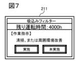
- FIG. 7 is a diagram showing an example of a message displayed on the display unit 208 of the second embodiment.
- the MSG 211 displays, for example, the part name "suction filter", the remaining operation time until maintenance "4000 hours", and a work instruction to the user to extend the maintenance period "clean or improve the surrounding environment".
- the work instruction to the user is registered in advance in the control device 207 for each part.
- the user can determine that maintenance is necessary without waiting for the maintenance scheduled one year after the reference date. This allows maintenance to be performed at an appropriate time depending on the condition of the parts.
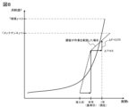
- FIG. 8 is a graph showing an example of the relationship between the wear rate F of a part and the period t in Example 2.
- the reference date is six months after the date of installation of the oil-lubricated screw compressor 200, and six months have passed since the reference date.
- the method of estimating the maintenance timing of the suction filter 202 from the calculation results of the control device 207 will be described with reference to the graph in Figure 8.
- the vertical axis of the graph indicates the wear level F
- the horizontal axis indicates the period t
- the solid line indicates ⁇ F/ ⁇ t.
- the wear level at which the suction filter 202 requires maintenance is 1, and the wear level at which the suction filter 202 is damaged is 1.2.
- the relationship between the wear rate ⁇ F calculated by the control device 207 and the period ⁇ t is shown by a dotted line. From the dotted line in Figure 8, it is estimated that the wear rate F will reach 1 one year after the installation date.
- the control device 207 calculates the remaining operating time until maintenance based on the graph in Figure 8, and displays a message on the display unit 208.
- FIG. 9 is a diagram showing an example of a message displayed on the display unit 208 of the second embodiment.
- the MSG 212 displays, for example, the part name "suction filter", the remaining operation time until maintenance "8000 hours", and a work instruction to the user to extend the maintenance period "clean or improve the surrounding environment".
- the work instruction to the user is registered in advance in the control device 207 for each part.
- the user can determine that regular maintenance should be performed one year after the installation date. This reduces the number of maintenance sessions and cuts maintenance costs.
- control device 207 transmits the suction pressure PS detected by the pressure detector 206 to the server 300 via the antenna 209.
- the CPU 201 performs calculations similar to those of the control device 207 described above, and displays a MSG 211 on the display unit 208.
- the CPU 201 may also display the MSG 211 on the display unit of the server 300.
- the control device 207 also displays instructions to the user on the display unit 208 to extend the maintenance interval, so that the user can carry out the work, thereby reducing the number of maintenance operations and lowering maintenance costs.
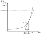
- FIG. 10 is a graph showing an example of the relationship between the wear level F of a part and the period t in Example 3.
- the part to be maintained in this example is an electrolytic capacitor built into the control device 207.
- the degree of wear ⁇ F of the electrolytic capacitor can be calculated from the time tE that electricity is passed through the electrolytic capacitor, which is recorded in the control device 207.
- the method for calculating the degree of wear ⁇ F of the electrolytic capacitor is shown below.
- the method of estimating the maintenance timing of the electrolytic capacitor from the calculation results of the control device 207 will be explained with reference to the graph in Figure 10.
- the vertical axis of the graph indicates the degree of wear F
- the horizontal axis indicates the period t
- the solid line indicates ⁇ F/ ⁇ t.
- the degree of wear at which the electrolytic capacitor requires maintenance is 1, and the degree of wear at which the electrolytic capacitor is damaged is 1.2.
- the relationship between the wear rate ⁇ F calculated by the control device 207 and the period ⁇ t is shown by a dotted line. From the dotted line in Figure 10, it is estimated that the wear rate F will reach 1 after 9 years from the reference date.
- the control device 207 calculates the remaining operating time until maintenance based on the graph in Figure 10, and displays a message on the display unit 208.
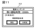
- FIG. 11 is a diagram showing an example of a message displayed on the display unit 208 of the third embodiment.
- the MSG 213 displays, for example, the part name "electrolytic capacitor", the remaining operating time until maintenance "12000 hours", and a work instruction to the user to extend the maintenance period "Improve the surrounding environment".
- the work instruction to the user is registered in advance in the control device 207 for each part.
- the user can decide to postpone the maintenance eight years from the base date and postpone it to nine years later. This will reduce the number of maintenances and cut maintenance costs.
- control device 207 estimates the maintenance timing of the electrolytic capacitor based on the current flow time tE of the electrolytic capacitor and displays the remaining operating time until maintenance on the display unit 208, so that the maintenance timing of the CBM parts of the gas compressor can be estimated and managed.
- the present invention is not limited to the above-described embodiments, but includes various modified examples.
- the above-described embodiments have been described in detail to clearly explain the present invention, and are not necessarily limited to those having all of the configurations described. It is also possible to replace part of the configuration of one embodiment with the configuration of another embodiment, and it is also possible to add the configuration of another embodiment to the configuration of one embodiment. It is also possible to add, delete, or replace part of the configuration of each embodiment with other configurations.
- 100...oil-free screw compressor 101...low-pressure stage compressor main body, 102...high-pressure stage compressor main body, 103...filter, 103A...suction port, 104...intercooler, 105...air piping, 106...air piping, 107...check valve, 108...aftercooler, 109...air piping, 110...low-pressure stage air release piping, 111...low-pressure stage air release piping, 112...low-pressure stage two-way air release valve, 113...low-pressure stage two-way air release valve, 114...high-pressure stage air release piping, 115...high-pressure stage air release piping, 116...high-pressure stage two-way air release valve, 117...high-pressure stage two-way air release valve, 118...pressure detection 119...control device, 120...discharge air piping, 121...pressure detector, 122...temperature detector, 123...display unit, 124...antenna, 125...network cloud, 126...suction throttle valve, 127...
Landscapes
- Engineering & Computer Science (AREA)
- Mechanical Engineering (AREA)
- General Engineering & Computer Science (AREA)
- Compressors, Vaccum Pumps And Other Relevant Systems (AREA)
Abstract
気体圧縮機のCBM部品のメンテナンス時期を推定し管理することができる技術を提供する。オイルフリースクリュー圧縮機100は、インタークーラ104から吐出される空気の温度である2段吸込み温度TS2を計測する温度検出器122と、2段吸込み温度TS2に基づいてインタークーラ104のメンテナンス時期を推定する制御装置119と、表示部123と、を備え、制御装置119は、メンテナンスまでの残り運転時間を表示部123に表示する。
Description
本発明は、気体圧縮機、及びその部品保守管理方法、並びに部品保守管理システムに関する。
気体圧縮機の各部品のメンテナンスは、TBM(Time Based Maintenance,時間基準整備)と呼ばれるあらかじめ設定された期間内に設備を保全する方式、またはCBM(Condition Based Maintenance,状態基準整備)と呼ばれる設備の状態の計測や監視を行い、異常の前触れを検知して保全する方式で行われるのが一般的である。
TBMの対象となる部品(以下、「TBM部品」という)のメンテナンスは、一般的に、1年から数年に1回、同時期に実施される。一方、CBMの対象となる部品(以下、「CBM部品」という)のメンテナンスは、部品の状態に応じて実施されるが、メンテナンス費用の観点からTBM部品のメンテナンスと同時期に実施されることが望ましい。
部品の保守時期を管理する技術として、特許文献1には、実際の装置の利用度に関連しない第1の保守インターバルに達したことに基いて、当該部品の保守を要求し、第1の保守インターバルに達したことに基いて、実際の装置の利用度に関連付けられた第2の保守インターバルに達したかを判断し、第2の保守インターバルに達していない場合には、保守要求を一時禁止し、第1の保守インターバルを延長することが記載されている。
特許文献1に記載された部品保守管理システムでは、実際の装置動作に関係なく設定された第1の保守インターバルと実際の装置動作に基づいて設定された第2の保守インターバルとを参照して、第1の保守インターバルを適宜延長できる。
しかしながら、特許文献1において、第2の保守インターバルに関連付けられた装置の動作は、部品に応じて、装置の実稼働時間、移動距離、稼働回数等であるとしているが、これらは各部品の状態を示すものではない。また、特許文献1では、部品の状態を把握し、部品の状態から推定できるCBM部品のメンテナンス時期を管理することについては開示されていない。
そこで、本発明は、気体圧縮機のCBM部品のメンテナンス時期を推定し管理することができる技術を提供することを目的とする。
上記課題を解決するために、代表的な本発明の気体圧縮機は、空気を圧縮する気体圧縮機において、気体圧縮機の部品の状態を取得する取得部と、状態に基づいて部品のメンテナンス時期を推定する処理部と、表示部とを備え、処理部は、推定したメンテナンス時期を表示部に表示する気体圧縮機。
本発明によれば、気体圧縮機のCBM部品のメンテナンス時期を推定し管理することができる。
上記した以外の課題、構成及び効果は、以下の実態形態の説明により明らかにされる。
以下、実施例を図面を用いて説明する。
図1は、実施例1に係る圧縮機の構成の一例を示す図である。
本実施例のオイルフリースクリュー圧縮機100は、低圧段圧縮機本体101と高圧段圧縮機本体102を有している。低圧段圧縮機本体101の吸込み流路には、周囲空気を濾過して低圧段圧縮機本体101に供給するためのフィルター103が取付けられており、このフィルター103の下流側には吸込み口103Aが形成されており、この吸込み口103Aの下流側には吸込み絞り弁126が形成されている。
低圧段圧縮機本体101の吐出側と高圧段圧縮機本体102の吸込み側との間には、インタークーラ104が設けられており、このインタークーラ104は低圧段圧縮機本体101とは空気配管105で、高圧段圧縮機本体102とは空気配管106で配管接続されている。高圧段圧縮機本体102の下流には、逆止弁107を介してアフタークーラ108が空気配管109で配管接続されている。
空気配管106の途中には、インタークーラ104から吐出される空気の温度を計測する温度検出器122と、インタークーラ104から吐出される空気の圧力を計測する圧力検出器118とが取付けられている。温度検出器122が検出した温度、及び圧力検出器118が検出した圧力は、制御装置119に入力される。
低圧段圧縮機本体101とインタークーラ104を接続する空気配管105の途中から、低圧段放気配管110と低圧段放気配管111がそれぞれ分岐している。低圧段放気配管110には低圧段放気二方弁112、低圧段放気配管111には低圧段放気二方弁113がそれぞれ設けられている。
同様に、高圧段圧縮機本体102とアフタークーラ108とを接続する空気配管109の途中であって逆止弁107の上流側から、高圧段放気配管114と高圧段放気配管115がそれぞれ分岐している。高圧段放気配管114には高圧段放気二方弁116、高圧段放気配管115には高圧段放気二方弁117がそれぞれ設けられている。
アフタークーラ108で冷却された圧縮空気を利用側に供給するため、吐出空気配管120がアフタークーラ108の下流に設けられている。この吐出空気配管120の途中には、オイルフリースクリュー圧縮機100から吐出される圧縮空気の圧力を計測する圧力検出器121が取付けられている。圧力検出器121が検出した圧力は、制御装置119に入力される。制御装置119に入力された入力値は制御装置119によって演算処理が行われ、処理に応じた内容とメンテナンスまでの残り運転時間などのメッセージが表示部123に表示される。
なお、制御装置119は、アンテナ124を介してネットワーククラウド125と通信可能に接続されていても良い。本実施例では、演算処理や、処理に応じた表示は制御装置119及び表示部123で実行する例を説明するが、アンテナ124を介して、ネットワーククラウド125と通信可能に接続し、演算処理や表示内容の指示をネットワーククラウド125上のサーバ300(図2)等で実行し、表示部123に表示させるように構成してもよく、サーバ300(図2)の表示部に表示するようにしてもよい。通信手段は、図1では一例としてアンテナ124としたが、有線または無線の他の通信手段であっても良い。
図2は、実施例1のサーバのハードウェア構成の一例を示すブロック図の例である。
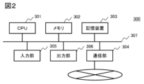
サーバ300はCPU(Central Processing Unit)201、メモリ302、記憶装置303、通信部304、入力部305、及び出力部306がバス307で相互に接続されて構成されるサーバもしくはコンピュータである。
CPU201は中央処理部であり、メモリ302(または記憶装置303)に保持しているプログラムを実行することで、必要な機能を実装する。メモリ302は、CPU201が処理を実行する際に利用する主記憶装置であり、RAM(Random Access Memory)等の揮発性記憶素子で構成される。記憶装置303は、CPU201に提供する入力データや、CPU201から出力される出力データを保管するための補助記憶装置であり、HDD(Hard Disk Drive)やSSD(Solid State Drive)等の不揮発性記憶素子で構成される。
通信部304は、サーバ300が外部装置との通信を行うために用いるインタフェースであり、NIC(Network Interface Card)等で構成される。通信部304はネットワーク(例えばインターネット)に接続され、ネットワークを介して外部装置との間で通信を行う。
入力部305は、ユーザからの入力を受け付けるインタフェースであり、キーボード、タッチパネル、カードリーダ、または音声入力装置等で構成される。出力部306は、操作者に対してデータの出力を行うインタフェースであり、ディスプレイ、スピーカ、またはプリンタ等で構成される。バス307は、サーバ300の内部通信路である。
本実施例のオイルフリースクリュー圧縮機100において、部品の状態を把握し、メンテナンス時期を推定する例を以下に説明する。
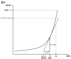
図3は、実施例1の部品の消耗度Fと期間tとの関係の一例を示すグラフである。本実施例のメンテナンス対象部品は、インタークーラ104である。
図3では、オイルフリースクリュー圧縮機100の導入日を基準日とし、基準日から1年が経過したものとする。
インタークーラ104は、TBM部品とした場合通常1年毎のメンテナンスが必要な部品であるが、CBM部品として期間Δtにおけるインタークーラ104の消耗度ΔFによりメンテナンス時期を推定することが可能である。インタークーラ104の消耗度は主にインタークーラ104内の冷却用フィンの消耗度に依存する。
インタークーラ104の消耗度ΔFは、温度検出器122で検出されるインタークーラ104から吐出される空気の温度である2段吸込み温度TS2の上昇から算出することができる。インタークーラ104の消耗度ΔFの算出方法を以下に示す。
温度検出器122から検出される2段吸込み温度TS2が基準日から現在までの1年間で10℃から15℃に変化したとすると、制御装置119は2段吸込み温度上昇値ΔTS2=15-10=5と演算する。
次に、メンテナンスが必要な2段吸込み温度上昇値ΔTS2Cを20K(=20deg)とすると、制御装置119は消耗度ΔF=ΔTS2/ΔTS2C=5/20=0.25と演算する。メンテナンスが必要な2段吸込み温度上昇値ΔTS2Cは、制御装置119に予め登録されている。基準日から1年経過したことから、制御装置119は期間Δt=1と演算する。
制御装置119の演算結果からインタークーラ104のメンテナンス時期を推定する方法を図3のグラフを基に説明する。グラフの縦軸は消耗度F、横軸は期間t、実線はΔF/Δtを示し、インタークーラ104のメンテナンスが必要な消耗度を1、インタークーラ104が破損に至る消耗度を1.2とする。
図3に制御装置119が演算した消耗度ΔFと期間Δtの関係を点線で示す。図3の点線から、消耗度Fが1に達するのは、基準日から2年後以降であることが推定される。制御装置119は、図3のグラフを基にメンテナンスまでの残り運転時間を算出し、表示部123にメッセージを表示する。
図4は、実施例1の表示部123に表示されるメッセージの一例を示す図である。図4に示すように、MSG127には、例えば、部品名「インタークーラ」、メンテナンスまでの残り運転時間「12000h」、メンテナンス時期を延長するためのユーザへの作業指示「清掃、または周囲環境改善」などが表示される。ユーザへの作業指示は、部品毎に制御装置119に予め登録されている。
ユーザは、MSG127を確認することによって、基準日から1年後のメンテナンスを見送り、基準日から2年後にメンテナンス実施を延長可能と判断することができる。これにより、メンテナンス回数を削減し、メンテナンス費用を軽減することができる。
なお、本実施例では、演算処理や、処理に応じた表示は制御装置119及び表示部123で実行する例を説明したが、アンテナ124を介して、ネットワーククラウド125と通信可能に接続し、演算処理や表示内容の指示をネットワーククラウド125上のサーバ300(図2)等で実行し、表示部123に表示させるように構成してもよく、サーバ300(図2)の表示部に表示するようにしてもよい。
この場合、制御装置119は、温度検出器122から検出される2段吸込み温度TS2をアンテナ124を介してサーバ300へ送信する。CPU201は、上記の制御装置119と同様の演算を行い、MSG127を表示部123に表示する。また、CPU201は、サーバ300の表示部にもMSG127を表示しても良い。
本実施例によれば、制御装置119は、温度検出器122から検出される2段吸込み温度TS2に基づいてインタークーラ104のメンテナンス時期を推定し、メンテナンスまでの残り運転時間を表示部123に表示するので、気体圧縮機のCBM部品のメンテナンス時期を推定し管理することができる。
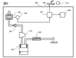
図5は、実施例2に係る圧縮機の構成の一例を示す図である。
本実施例の給油式スクリュー圧縮機200は、圧縮機本体201を有している。圧縮機本体201の吸込み流路には、周囲空気を濾過して圧縮機本体201に供給するための吸込みフィルター202が取付けられており、この吸込みフィルター202の下流側には吸込み絞り弁203が形成されている。
吸込みフィルター202には吸込みフィルター202内の圧力を計測する圧力検出器206が取付けられている。圧力検出器206が検出した圧力は、制御装置207に入力される。制御装置207に入力された入力値は制御装置207によって演算処理が行われ、処理に応じた内容とメンテナンスまでの残り運転時間などのメッセージが表示部208に表示される。
なお、制御装置207は、アンテナ209を介してネットワーククラウド210と通信可能に接続されていても良い。本実施例では、演算処理や、処理に応じた表示は制御装置207及び表示部208で実行する例を説明するが、アンテナ209を介して、ネットワーククラウド210と通信可能に接続し、演算処理や表示内容の指示をネットワーククラウド210上のサーバ300(図2)等で実行し、表示部208に表示させるように構成してもよく、サーバ300(図2)の表示部に表示するようにしてもよい。通信手段は、図1では一例としてアンテナ209としたが、有線または無線の他の通信手段であっても良い。
圧縮機本体201の吐出側には圧縮空気と油の気液混合気体を分離する油分離タンク204が設けられ、油分離タンク204の下流側には圧縮空気を冷却するためのアフタークーラ205が設けられている。
制御装置207には、図示しないが電解コンデンサが組み込まれている。
本実施例の給油式スクリュー圧縮機200において、部品の状態を把握し、メンテナンス時期を推定する例を以下に説明する。
図6は、実施例2の部品の消耗度Fと期間tとの関係の一例を示すグラフである。本実施例のメンテナンス対象部品は、吸込みフィルター202である。
図6では、給油式スクリュー圧縮機200の導入日を基準日とし、基準日から半年が経過したものとする。
吸込みフィルター202は、TBM部品とした場合通常1年毎のメンテナンスが必要な部品であるが、CBM部品として期間Δtにおける吸込みフィルター202の消耗度ΔFによりメンテナンス時期を推定することが可能である。吸込みフィルター202の消耗度は主に吸込みフィルターの目詰まりに依存する。
吸込みフィルター202の消耗度ΔFは、圧力検出器206で検出される吸込みフィルター202内の圧力である吸入圧力PSの低下から算出することができる。吸込みフィルター202の消耗度ΔFの算出方法を以下に示す。
圧力検出器206から検出される吸入圧力PSが基準日から現在までの半年間で-1.5kPaから-3.5kPaに変化したとすると、制御装置207は吸入圧力低下値ΔPS=-3.5-(-1.5)=-2と演算する。
次に、メンテナンスが必要な吸入圧力低下値ΔPSCを-4とすると、制御装置207は消耗度ΔF=ΔPS/ΔPSC=-2/-4=0.5と演算する。メンテナンスが必要な吸入圧力低下値ΔPSCは、制御装置207に予め登録されている。基準日から半年経過したことから、制御装置207は期間Δt=0.5と演算する。
制御装置207の演算結果から吸込みフィルター202のメンテナンス時期を推定する方法を図6のグラフを基に説明する。グラフの縦軸は消耗度F、横軸は期間t、実線はΔF/Δtを示し、吸込みフィルター202のメンテナンスが必要な消耗度を1、吸込みフィルター202が破損に至る消耗度を1.2とする。
図6に制御装置207が演算した消耗度ΔFと期間Δtの関係を点線で示す。図6の点線から、消耗度Fが1に達するのは、基準日から1年以内であることが推定される。制御装置207は、図6のグラフを基にメンテナンスまでの残り運転時間を算出し、表示部208にメッセージを表示する。
図7は、実施例2の表示部208に表示されるメッセージの一例を示す図である。図7に示すように、MSG211には、例えば、部品名「吸込みフィルター」、メンテナンスまでの残り運転時間「4000h」、メンテナンス時期を延長するためのユーザへの作業指示「清掃、または周囲環境改善」などが表示される。ユーザへの作業指示は、部品毎に制御装置207に予め登録されている。
ユーザは、MSG211を確認することによって、基準日から1年後のメンテナンスを待たずにメンテナンス実施が必要と判断することができる。これにより、部品の状態に応じて適切な時期にメンテナンスを実施することができる。
次に、ユーザが、MSG211の作業指示に従って、周囲環境改善、部品の清掃、設定圧力の変更、運転方式の変更等のメンテナンス時期を延長するための作業を実施した場合の期間Δtにおける吸込みフィルター202の消耗度ΔFの算出方法を以下に示す。
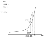
図8は、実施例2の部品の消耗度Fと期間tとの関係の一例を示すグラフである。
図8では、給油式スクリュー圧縮機200の導入日から半年後を基準日とし、基準日から半年が経過したものとする。
ユーザが基準日以降に吸込みフィルター202の清掃、または給油式スクリュー圧縮機200の周囲環境改善を実施したことにより、圧力検出器206から検出される吸入圧力PSが基準日から現在までの半年間で-3.5kPaから-5kPaに変化したとすると、制御装置207は吸入圧力低下値ΔPS=-5-(-3.5)=-1.5と演算する。
次に、メンテナンスが必要な吸入圧力低下値ΔPSCを-4とすると、制御装置207は消耗度ΔF=ΔPS/ΔPSC=-1.5/-4=0.375と演算する。メンテナンスが必要な吸入圧力低下値ΔPSCは、制御装置207に予め登録されている。基準日から半年経過したことから、制御装置207は期間Δt=0.5と演算する。
制御装置207の演算結果から吸込みフィルター202のメンテナンス時期を推定する方法を図8のグラフを基に説明する。グラフの縦軸は消耗度F、横軸は期間t、実線はΔF/Δtを示し、吸込みフィルター202のメンテナンスが必要な消耗度を1、吸込みフィルター202が破損に至る消耗度を1.2とする。
図8に制御装置207が演算した消耗度ΔFと期間Δtの関係を点線で示す。図8の点線から、消耗度Fが1に達するのは導入日から1年後以降となることが推定される。制御装置207は、図8のグラフを基にメンテナンスまでの残り運転時間を算出し、表示部208にメッセージを表示する。
図9は、実施例2の表示部208に表示されるメッセージの一例を示す図である。図9に示すように、MSG212には、例えば、部品名「吸込みフィルター」、メンテナンスまでの残り運転時間「8000h」、メンテナンス時期を延長するためのユーザへの作業指示「清掃、または周囲環境改善」などが表示される。ユーザへの作業指示は、部品毎に制御装置207に予め登録されている。
ユーザは、MSG211を確認することによって、導入日から1年後の通常のメンテナンスを実施すればよいと判断することができる。これにより、メンテナンス回数を削減し、メンテナンス費用を軽減することができる。
なお、本実施例では、演算処理や、処理に応じた表示は制御装置207及び表示部208で実行する例を説明するが、アンテナ209を介して、ネットワーククラウド210と通信可能に接続し、演算処理や表示内容の指示をネットワーククラウド210上のサーバ300(図2)等で実行し、表示部208に表示させるように構成してもよく、サーバ300(図2)の表示部に表示するようにしてもよい。
この場合、制御装置207は、圧力検出器206から検出される吸入圧力PSをアンテナ209を介してサーバ300へ送信する。CPU201は、上記の制御装置207と同様の演算を行い、MSG211を表示部208に表示する。また、CPU201は、サーバ300の表示部にもMSG211を表示しても良い。
本実施例によれば、制御装置207は、圧力検出器206から検出される吸入圧力PSに基づいて吸込みフィルター202のメンテナンス時期を推定し、メンテナンスまでの残り運転時間を表示部208に表示するので、気体圧縮機のCBM部品のメンテナンス時期を推定し管理することができる。
また、制御装置207は、メンテナンス時期を延長するためのユーザへの作業指示を表示部208に表示するので、ユーザが作業を実施することにより、メンテナンス回数を削減し、メンテナンス費用を軽減することができる。
実施例3に係る圧縮機の構成は、図5と同様である。
図10は、実施例3の部品の消耗度Fと期間tとの関係の一例を示すグラフである。本実施例のメンテナンス対象部品は、制御装置207に組み込まれている電解コンデンサである。
図10では、給油式スクリュー圧縮機200の導入日を基準日とし、基準日から8年が経過したものとする。
電解コンデンサは、TBM部品とした場合通常8年毎のメンテナンスが必要な部品であるが、CBM部品として期間Δtにおける電解コンデンサの消耗度ΔFによりメンテナンス時期を推定することが可能である。
電解コンデンサの消耗度は主に通電時間に依存するため、電解コンデンサの消耗度ΔFは、制御装置207に記録される電解コンデンサの通電時間tEから算出することができる。電解コンデンサの消耗度ΔFの算出方法を以下に示す。
制御装置207に記録される通電時間tEは、給油式スクリュー圧縮機200の運転時間に比例し、基準日から現在までの通電時間を42000時間とすると、制御装置207は通電時間ΔtE=42000と演算する。
次に、メンテナンスが必要な通電時間ΔtECを48000とすると、制御装置207は消耗度ΔF=ΔtE/ΔtEC=42000/48000=0.875と演算する。メンテナンスが必要な通電時間ΔtECは、制御装置207に予め登録されている。基準日から8年経過したことから、制御装置207は期間Δt=8と演算する。
制御装置207の演算結果から電解コンデンサのメンテナンス時期を推定する方法を図10のグラフを基に説明する。グラフの縦軸は消耗度F、横軸は期間t、実線はΔF/Δtを示し、電解コンデンサのメンテナンスが必要な消耗度を1、電解コンデンサが破損に至る消耗度を1.2とする。
図10に制御装置207が演算した消耗度ΔFと期間Δtの関係を点線で示す。図10の点線から、消耗度Fが1に達するのは、基準日から9年後以降であることが推定される。制御装置207は、図10のグラフを基にメンテナンスまでの残り運転時間を算出し、表示部208にメッセージを表示する。
図11は、実施例3の表示部208に表示されるメッセージの一例を示す図である。図11に示すように、MSG213には、例えば、部品名「電解コンデンサ」、メンテナンスまでの残り運転時間「12000h」、メンテナンス時期を延長するためのユーザへの作業指示「周囲環境改善」などが表示される。ユーザへの作業指示は、部品毎に制御装置207に予め登録されている。
ユーザは、MSG213を確認することによって、基準日から8年後のメンテナンスを見送り、9年後にメンテナンス実施を延長可能と判断することができる。これにより、メンテナンス回数を削減し、メンテナンス費用を軽減することができる。
なお、本実施例では、演算処理や、処理に応じた表示は制御装置207及び表示部208で実行する例を説明するが、アンテナ209を介して、ネットワーククラウド210と通信可能に接続し、演算処理や表示内容の指示をネットワーククラウド210上のサーバ300(図2)等で実行し、表示部208に表示させるように構成してもよく、サーバ300(図2)の表示部に表示するようにしてもよい。
この場合、制御装置207は、電解コンデンサの通電時間tEをアンテナ209を介してサーバ300へ送信する。CPU201は、上記の制御装置207と同様の演算を行い、MSG213を表示部208に表示する。また、CPU201は、サーバ300の表示部にもMSG213を表示しても良い。
本実施例によれば、制御装置207は、電解コンデンサの通電時間tEに基づいて電解コンデンサのメンテナンス時期を推定し、メンテナンスまでの残り運転時間を表示部208に表示するので、気体圧縮機のCBM部品のメンテナンス時期を推定し管理することができる。
上記実施例1~3では、メンテナンス対象部品として、インタークーラ、吸込みフィルター、電解コンデンサを例に説明したが、これに限定されるものではなく、本発明は他の部品にも適用可能である。
なお、本発明は上記した実施例に限定されるものではなく、様々な変形例が含まれる。例えば、上記した実施例は本発明を分かりやすく説明するために詳細に説明したものであり、必ずしも説明した全ての構成を備えるものに限定されるものではない。また、ある実施例の構成の一部を他の実施例の構成に置き換えることが可能であり、また、ある実施例の構成に他の実施例の構成を加えることも可能である。また、各実施例の構成の一部について、他の構成の追加・削除・置換をすることが可能である。
100…オイルフリースクリュー圧縮機、101…低圧段圧縮機本体、102…高圧段圧縮機本体、103…フィルター、103A…吸込み口、104…インタークーラ、105…空気配管、106…空気配管、107…逆止弁、108…アフタークーラ、109…空気配管、110…低圧段放気配管、111…低圧段放気配管、112…低圧段放気二方弁、113…低圧段放気二方弁、114…高圧段放気配管、115…高圧段放気配管、116…高圧段放気二方弁、117…高圧段放気二方弁、118…圧力検出器、119…制御装置、120…吐出空気配管、121…圧力検出器、122…温度検出器、123…表示部、124…アンテナ、125…ネットワーククラウド、126…吸込み絞り弁、127…MSG、200…給油式スクリュー圧縮機、201…圧縮機本体、202…吸込みフィルター、203…吸込み絞り弁、204…油分離タンク、205…アフタークーラ、206…圧力検出器、207…制御装置、208…表示部、209…アンテナ、210…ネットワーククラウド、211、212、213…MSG
Claims (12)
- 空気を圧縮する気体圧縮機において、
前記気体圧縮機の部品の状態を取得する取得部と、
前記状態に基づいて前記部品のメンテナンス時期を推定する処理部と、
表示部とを備え、
前記処理部は、
前記推定したメンテナンス時期を前記表示部に表示する気体圧縮機。 - 請求項1記載の気体圧縮機において、
前記処理部は、
前記部品のメンテナンス時期を延長するためのユーザへの作業指示を前記表示部に表示する気体圧縮機。 - 請求項2記載の気体圧縮機において、
前記処理部は、
基準日から現在までの前記部品の状態の変化に基づいて前記メンテナンス時期を推定する気体圧縮機。 - 請求項2記載の気体圧縮機において、
前記処理部は、
基準日から現在までの前記部品の使用時間に基づいて前記メンテナンス時期を推定する気体圧縮機。 - 空気を圧縮する気体圧縮機の部品保守管理方法において、
前記気体圧縮機の部品の状態を取得し、
前記状態に基づいて前記部品のメンテナンス時期を推定し、
前記推定したメンテナンス時期を表示部に表示する部品保守管理方法。 - 請求項5記載の部品保守管理方法において、
前記部品のメンテナンス時期を延長するためのユーザへの作業指示を前記表示部に表示する部品保守管理方法。 - 請求項6記載の部品保守管理方法において、
基準日から現在までの前記部品の状態の変化に基づいて前記メンテナンス時期を推定する部品保守管理方法。 - 請求項6記載の部品保守管理方法において、
基準日から現在までの前記部品の使用時間に基づいて前記メンテナンス時期を推定する部品保守管理方法。 - 空気を圧縮する気体圧縮機と、前記気体圧縮機と通信可能に接続されたサーバとを備える部品保守管理システムにおいて、
前記気体圧縮機は、
前記気体圧縮機の部品の状態を取得する取得部を備え、
前記サーバは、
前記状態に基づいて前記部品のメンテナンス時期を推定する処理部を備え、
前記気体圧縮機及び前記サーバの少なくとも一方は、表示部を備え、
前記処理部は、
前記推定したメンテナンス時期を前記表示部に表示する部品保守管理システム。 - 請求項9記載の部品保守管理システムにおいて、
前記処理部は、
前記部品のメンテナンス時期を延長するためのユーザへの作業指示を前記表示部に表示する部品保守管理システム。 - 請求項10記載の部品保守管理システムにおいて、
前記処理部は、
基準日から現在までの前記部品の状態の変化に基づいて前記メンテナンス時期を推定する部品保守管理システム。 - 請求項10記載の部品保守管理システムにおいて、
前記処理部は、
基準日から現在までの前記部品の使用時間に基づいて前記メンテナンス時期を推定する部品保守管理システム。
Priority Applications (2)
| Application Number | Priority Date | Filing Date | Title |
|---|---|---|---|
| PCT/JP2023/029943 WO2025041216A1 (ja) | 2023-08-21 | 2023-08-21 | 気体圧縮機、及びその部品保守管理方法、並びに部品保守管理システム |
| JP2025541178A JPWO2025041216A1 (ja) | 2023-08-21 | 2023-08-21 |
Applications Claiming Priority (1)
| Application Number | Priority Date | Filing Date | Title |
|---|---|---|---|
| PCT/JP2023/029943 WO2025041216A1 (ja) | 2023-08-21 | 2023-08-21 | 気体圧縮機、及びその部品保守管理方法、並びに部品保守管理システム |
Publications (1)
| Publication Number | Publication Date |
|---|---|
| WO2025041216A1 true WO2025041216A1 (ja) | 2025-02-27 |
Family
ID=94731701
Family Applications (1)
| Application Number | Title | Priority Date | Filing Date |
|---|---|---|---|
| PCT/JP2023/029943 Pending WO2025041216A1 (ja) | 2023-08-21 | 2023-08-21 | 気体圧縮機、及びその部品保守管理方法、並びに部品保守管理システム |
Country Status (2)
| Country | Link |
|---|---|
| JP (1) | JPWO2025041216A1 (ja) |
| WO (1) | WO2025041216A1 (ja) |
Citations (2)
| Publication number | Priority date | Publication date | Assignee | Title |
|---|---|---|---|---|
| JP2003091313A (ja) * | 2001-09-17 | 2003-03-28 | Hitachi Ltd | 圧縮機の遠隔監視システム |
| WO2020066629A1 (ja) * | 2018-09-28 | 2020-04-02 | 株式会社日立産機システム | 気体圧縮機 |
-
2023
- 2023-08-21 WO PCT/JP2023/029943 patent/WO2025041216A1/ja active Pending
- 2023-08-21 JP JP2025541178A patent/JPWO2025041216A1/ja active Pending
Patent Citations (2)
| Publication number | Priority date | Publication date | Assignee | Title |
|---|---|---|---|---|
| JP2003091313A (ja) * | 2001-09-17 | 2003-03-28 | Hitachi Ltd | 圧縮機の遠隔監視システム |
| WO2020066629A1 (ja) * | 2018-09-28 | 2020-04-02 | 株式会社日立産機システム | 気体圧縮機 |
Also Published As
| Publication number | Publication date |
|---|---|
| JPWO2025041216A1 (ja) | 2025-02-27 |
Similar Documents
| Publication | Publication Date | Title |
|---|---|---|
| US10401879B2 (en) | Topological connectivity and relative distances from temporal sensor measurements of physical delivery system | |
| CN112005069B (zh) | 冷冻干燥处理和装备健康状况监测 | |
| CN103793752B (zh) | 一种基于退化建模的设备失效次数预测方法 | |
| EP3598258B1 (en) | Risk assessment device, risk assessment system, risk assessment method, and risk assessment program | |
| US9652728B2 (en) | Methods and systems for generating a business process control chart for monitoring building processes | |
| US20110106747A1 (en) | Turbine life assessment and inspection system and methods | |
| CN114353854A (zh) | 用于在线定位异常传感器的方法、设备和介质 | |
| CN109344983A (zh) | 故障检测方法、装置及计算机可读存储介质 | |
| US20140074867A1 (en) | Methods and systems for evaluating the performance of building processes | |
| WO2017077970A1 (ja) | 真空ポンプの判断システム、および真空ポンプ | |
| KR102693299B1 (ko) | 청정도 자동 제어 파티클 카운터 및 모니터링 시스템 | |
| WO2025041216A1 (ja) | 気体圧縮機、及びその部品保守管理方法、並びに部品保守管理システム | |
| US10942508B2 (en) | Risk assessment device, risk assessment system, risk assessment method, risk assessment program, and data structure | |
| US20090120111A1 (en) | Remote Diagnostics and Prognostics for Refrigerant Systems | |
| CN115307669A (zh) | 用于检测被测系统的异常传感器的方法、设备和介质 | |
| CN104160152A (zh) | 空气压缩机的监视系统 | |
| CN118959401B (zh) | 一种电液比例伺服阀突发性故障的实时诊断方法、设备、介质及产品 | |
| US20240151230A1 (en) | Method for detecting and monitoring condensate in an oil system of an oil-injected compressor or vacuum pump | |
| JP2003131726A (ja) | エネルギ消費量監視方法及び監視システム | |
| CN117786352A (zh) | 滤清器滤芯寿命预测方法及设备 | |
| CN109766243A (zh) | 一种基于幂函数的多核主机性能监控方法 | |
| JP6482742B1 (ja) | リスク評価装置、リスク評価システム、リスク評価方法、及び、リスク評価プログラム | |
| US20130124256A1 (en) | Method and system for monitoring plant assets | |
| TWI854848B (zh) | 監控裝置、監控方法及其電腦程式產品 | |
| WO2025120929A1 (ja) | 機器状態診断装置及び機器状態診断方法 |
Legal Events
| Date | Code | Title | Description |
|---|---|---|---|
| 121 | Ep: the epo has been informed by wipo that ep was designated in this application |
Ref document number: 23949677 Country of ref document: EP Kind code of ref document: A1 |
|
| ENP | Entry into the national phase |
Ref document number: 2025541178 Country of ref document: JP Kind code of ref document: A |
|
| WWE | Wipo information: entry into national phase |
Ref document number: 2025541178 Country of ref document: JP |
|
| NENP | Non-entry into the national phase |
Ref country code: DE |