WO2025041209A1 - 無線装置及び制御方法 - Google Patents
無線装置及び制御方法 Download PDFInfo
- Publication number
- WO2025041209A1 WO2025041209A1 PCT/JP2023/029897 JP2023029897W WO2025041209A1 WO 2025041209 A1 WO2025041209 A1 WO 2025041209A1 JP 2023029897 W JP2023029897 W JP 2023029897W WO 2025041209 A1 WO2025041209 A1 WO 2025041209A1
- Authority
- WO
- WIPO (PCT)
- Prior art keywords
- ris
- information
- wireless device
- codeword
- signal
- Prior art date
- Legal status (The legal status is an assumption and is not a legal conclusion. Google has not performed a legal analysis and makes no representation as to the accuracy of the status listed.)
- Pending
Links
Images


Classifications
-
- H—ELECTRICITY
- H04—ELECTRIC COMMUNICATION TECHNIQUE
- H04B—TRANSMISSION
- H04B7/00—Radio transmission systems, i.e. using radiation field
- H04B7/02—Diversity systems; Multi-antenna system, i.e. transmission or reception using multiple antennas
- H04B7/04—Diversity systems; Multi-antenna system, i.e. transmission or reception using multiple antennas using two or more spaced independent antennas
- H04B7/0413—MIMO systems
- H04B7/0456—Selection of precoding matrices or codebooks, e.g. using matrices antenna weighting
-
- H—ELECTRICITY
- H04—ELECTRIC COMMUNICATION TECHNIQUE
- H04B—TRANSMISSION
- H04B7/00—Radio transmission systems, i.e. using radiation field
- H04B7/02—Diversity systems; Multi-antenna system, i.e. transmission or reception using multiple antennas
- H04B7/04—Diversity systems; Multi-antenna system, i.e. transmission or reception using multiple antennas using two or more spaced independent antennas
- H04B7/06—Diversity systems; Multi-antenna system, i.e. transmission or reception using multiple antennas using two or more spaced independent antennas at the transmitting station
Definitions
- This disclosure relates to a wireless device and a control method.
- the 3rd Generation Partnership Project (3GPP) is developing specifications for the 5th generation mobile communication system (5G, also known as New Radio (NR) or Next Generation (NG)) and is also developing specifications for the next generation, known as Beyond 5G, 5G Evolution or 6G.
- 5G also known as New Radio (NR) or Next Generation (NG)
- NG Next Generation
- Radio base stations which may be called simply base stations
- RIS Reconfigurable Intelligent Surface
- One aspect of the present disclosure provides a wireless device and a control method that can perform control to generate an appropriate beam according to the coverage area.
- a wireless device includes a control unit that determines a code word based on a geometric relationship between the wireless device and an area covered by the wireless device, and applies the code word to generate a beam that covers the area, and a communication unit that outputs a signal using the beam.
- FIG. 1 is a diagram illustrating an example of a wireless communication system according to an embodiment of the present disclosure.
- FIG. 2 illustrates an example of a distant user in the high frequency band.
- FIG. 1 illustrates an example of a non-line-of-sight user in the high frequency band.
- FIG. 1 is a diagram showing an example of communication using the configuration of an NCR.
- FIG. 1 is a diagram showing an example of communication using a RIS.
- FIG. 1 illustrates an example of a system architecture including a RIS. This figure shows an example of the near field (NF) and far field (FF) of a RIS.
- FIG. 1 illustrates an example of DFT-based beamforming (BF).
- FIG. 1 illustrates an example of beam focusing with optimal phase.
- FIG. 1 illustrates an example of beam focusing with near field (NF) steering vectors.
- FIG. 13 is a diagram illustrating an example of a precoder according to Example 1-1-1.
- FIG. 13 is a diagram illustrating an example of a reference point.
- FIG. 13 is a diagram illustrating an example of a precoder according to Example 1-1-2.
- FIG. 2 illustrates an example of a uniform grid in Cartesian coordinates.
- FIG. 11 is a diagram illustrating a first example of calculation of a focal position.
- FIG. 11 is a diagram illustrating a second example of calculation of a focal position.
- FIG. 13 is a diagram showing an example of a generated wide beam.
- FIG. 1 is a diagram illustrating an example of multi-wide beam generation.
- FIG. 13 is a diagram showing an example of Proposal 3.
- a diagram showing a first example of use case 1. A diagram showing a second example of use case 1.
- FIG. 1 is a diagram showing Alt. 1 of a second example of use case 1.
- FIG. 2 is a diagram showing Alt. 2 of a second example of use case 1.
- FIG. 2 is a block diagram showing an example of a configuration of a base station according to an embodiment of the present disclosure.
- FIG. 2 is a block diagram showing an example of a configuration of a terminal according to an embodiment of the present disclosure.
- FIG. 1 is a block diagram showing an example of a configuration of a wireless device according to an embodiment of the present disclosure.
- FIG. 2 is a diagram illustrating an example of a hardware configuration of a base station, a terminal, and a wireless device according to an embodiment of the present disclosure.
- FIG. 1 is a diagram illustrating an example of a configuration of a vehicle.
- existing technologies are used as appropriate.
- the existing technologies are, for example, existing LTE or existing NR, but are not limited to existing LTE and NR.
- SS Synchronization signal
- PSS Primary SS
- SSS Secondary SS
- PBCH Physical broadcast channel
- PRACH Physical random access channel
- PDCCH Physical Downlink Control Channel
- PDSCH Physical Downlink Shared Channel
- PUCCH Physical Uplink Control Channel
- PUSCH Physical Uplink Shared Channel
- NR corresponds to NR-SS, NR-PSS, NR-SSS, NR-PBCH, NR-PRACH, etc.
- NR- even if a signal is used in NR, it is not necessarily specified as "NR-".
- the duplex method may be a TDD (Time Division Duplex) method, an FDD (Frequency Division Duplex) method, or another method (e.g., Flexible Duplex, etc.).
- TDD Time Division Duplex
- FDD Frequency Division Duplex
- another method e.g., Flexible Duplex, etc.
- “configuring" wireless parameters and the like may mean that predetermined values are pre-configured, or that wireless parameters notified from a base station or terminal are configured.
- ⁇ Wireless communication system> 1 is a diagram illustrating an example of a wireless communication system 10 according to an embodiment of the present disclosure.
- the wireless communication system 10 is a wireless communication system conforming to 5G NR or 6G NR, and includes a Next Generation-Radio Access Network 20 (hereinafter, NG-RAN 20) and a terminal 200 (hereinafter, also referred to as UE (User Equipment) 200).
- NG-RAN 20 Next Generation-Radio Access Network 20
- UE User Equipment
- the wireless communication system 10 may be a wireless communication system conforming to a method called Beyond 5G, 5G Evolution, or 6G.
- NG-RAN 20 includes a base station 100 (hereinafter also referred to as gNB 100). Note that the number of gNBs and UEs is not limited to the example shown in FIG. 1.
- NG-RAN 20 actually includes multiple NG-RAN nodes, specifically, gNBs (or ng-eNBs), and is connected to a core network conforming to 5G or 6G.
- gNBs or ng-eNBs
- NG-RAN 20 and the core network may simply be expressed as a "network.”
- gNB may be read as a network (NW).
- the gNB 100 is, as an example, a base station conforming to 5G or 6G and performs wireless communication conforming to 5G or 6G with the UE 200.
- a radio device 300 that transfers signals between the gNB 100 and the UE 200 is shown.
- the radio device 300 may be referred to as a RIS (Reconfigurable Intelligent Surface).
- the wireless device 300 performs a forwarding operation to forward, for example, a signal transmitted from the gNB 100 to the UE 200.
- the wireless device 300 may also perform a forwarding operation to forward a signal transmitted from the UE 200 to the gNB 100.
- forward may be replaced with “relay.”
- operation may be replaced with “processing,” “control,” etc.
- the RIS which is an example of the wireless device 300 being considered in NR, will be described below.
- the gNB 100 and UE 200 may support MIMO (Multiple-Input Multiple-Output), which generates more directional beams by controlling radio signals transmitted from multiple antenna elements, carrier aggregation (CA: Carrier Aggregation), which bundles and uses multiple component carriers (CC: Component Carriers), and dual connectivity (DC: Dual Connectivity), which communicates between the UE and each of two NG-RAN nodes.
- MIMO Multiple-Input Multiple-Output
- CA Carrier Aggregation
- CC Component Carriers
- DC Dual Connectivity
- the wireless communication system 10 may be compatible with a plurality of frequency ranges (FR).
- the wireless communication system 10 may be compatible with FR1 and FR2.
- the frequency bands of each FR are, for example, as follows: ⁇ FR1: 410MHz to 7.125GHz ⁇ FR2: 24.25GHz to 52.6GHz
- FR1 may use a sub-carrier spacing (SCS) of 15 kHz, 30 kHz or 60 kHz, and a bandwidth (BW) of 5 to 100 MHz.
- FR2 is a higher frequency than FR1, and may use an SCS of 60 kHz or 120 kHz (which may include 240 kHz), and a bandwidth (BW) of 50 to 400 MHz.
- SCS may also be interpreted as numerology. Numerology is defined in 3GPP TS 38.300 and corresponds to one subcarrier spacing in the frequency domain.
- the wireless communication system 10 may support a higher frequency band than the FR2 frequency band. Specifically, the wireless communication system 10 may support a frequency band exceeding 52.6 GHz up to 114.25 GHz. Such a high frequency band may be referred to as "FR2x" for convenience.
- FR2x frequency band exceeding 52.6 GHz
- CP-OFDM Cyclic Prefix - Orthogonal Frequency Division Multiplexing
- DFT-S-OFDM Discrete Fourier Transform - Spread - Orthogonal Frequency Division Multiplexing
- the time direction (t) may be referred to as the time domain, symbol period, or symbol time, etc.
- the frequency direction may be referred to as the frequency domain, resource block, subcarrier, bandwidth part (BWP), etc.
- the gNB100 transmits control information, configuration information, etc. of the gNB100 to the UE200 as a downlink (DL) signal.
- DL downlink
- gNB100 receives control information, data signals, information regarding the processing capabilities of UE200 (terminal capabilities (information); for example, UE capability), etc., from UE200 as uplink (UL) signals.
- the wireless device 300 performs a forwarding operation to forward the DL signal to the UE 200.
- the wireless device 300 also performs a forwarding operation to forward the UL signal to the gNB 100.
- the UL signal that the gNB 100 receives from the UE 200 and/or the DL signal that the UE 200 receives from the gNB 100 may be a signal forwarded by the wireless device 300.
- UE200 is a communication device equipped with wireless communication capabilities, such as a smartphone, mobile phone, tablet, wearable device, or M2M (Machine-to-Machine) communication module.
- wireless communication capabilities such as a smartphone, mobile phone, tablet, wearable device, or M2M (Machine-to-Machine) communication module.
- UE200 receives control signals or data signals from gNB100 on DL and transmits control signals or data signals to gNB100 on UL to utilize various communication services provided by wireless communication system 10.
- UE200 also receives various reference signals transmitted from gNB100 and performs measurement of propagation path quality based on the reception results of the reference signals.
- Channels used to transmit DL signals include, for example, data channels and control channels.
- the data channel may include a physical downlink shared channel (PDSCH)
- the control channel may include a physical downlink control channel (PDCCH).
- PDSCH is an example of a downlink shared channel
- PDCCH is an example of a downlink control channel.
- PDCCH may be interpreted as downlink control information (DCI), control information, etc. transmitted in PDCCH.
- the reference signals included in the DL signal may include, for example, at least one of DMRS (Demodulation Reference Signal), PTRS (Phase Tracking Reference Signal), CSI-RS (Channel State Information - Reference Signal), SRS (Sounding Reference Signal), and PRS (Positioning Reference Signal) for position information.
- DMRS Demodulation Reference Signal
- PTRS Phase Tracking Reference Signal
- CSI-RS Channel State Information - Reference Signal
- SRS Sounding Reference Signal
- PRS Positioning Reference Signal
- Channels used to transmit UL signals include, for example, data channels and control channels.
- the data channel may include a physical uplink shared channel (PUSCH)
- the control channel may include a physical uplink control channel (PUCCH).
- PUSCH is an example of an uplink shared channel
- PUCCH is an example of an uplink control channel.
- the shared channel may be called a data channel.
- PUSCH or PUCCH may be interpreted as uplink control information (UCI), control information, etc. transmitted in PUSCH or PUCCH.
- the reference signal included in the UL signal may include, for example, at least one of DMRS, PTRS, CSI-RS, SRSRS, and PRS for location information.
- reference signals such as DMRS and PTRS are used to demodulate the UL data signal and are transmitted using the PUSCH.
- NR MIMO NR MIMO
- LOS-MIMO a very large bandwidth is required to achieve a data rate of 100 Gbps, which is difficult to secure.
- LOS-MIMO schemes that have already been considered require fixed transmitting and receiving positions, making them unsuitable for access links or requiring too large array sizes.
- the RIS may control the direction of the reflected signal or the direction of the transmitted (refracted) signal.
- reflection, transmission, and refraction may be interpreted as interchangeable.
- reflection, transmission, and refraction of a signal at a RIS may be understood as the RIS receiving a signal transmitted from a specific direction and transmitting (or) a signal in the same direction as the specific direction or in a direction different from the specific direction.
- the signal transmitted by the RIS may be the same signal as the signal received by the RIS, or may be a signal received by the RIS that has been subjected to specific processing.
- forwarding processing at a RIS may be understood as processing in which at least one of reflection, transmission, and refraction occurs at the RIS.
- RIS can provide beam gain with narrowband beams, an increase in the number of RIS beams (beams reflected/refracted by the RIS) is required.
- the RIS may be installed on objects such as buildings.
- FIG. 3A is a diagram showing an example of communication using the NCR configuration.
- the NCR may include an NCR-mobile termination (MT) and an NCR-forwarding (Fwd).
- the NCR-MT communicates with the BS (gNB) via a control link.
- gNB BS
- Communication between the NCR-MT and the BS may include at least one of receiving configuration/instruction/control information from the BS and sending requests/reports/responses to the BS.
- the NCR-Fwd relays communications between the BS and the UE by relaying/amplifying from the backhaul link to the access link and from the access link to the backhaul link.
- FIG. 3B is a diagram showing an example of communication using a RIS.
- the RIS relays communication between the BS and the UE by controlling the reflection angle in at least one of the reflection from the backhaul link to the access link and the reflection from the access link to the backhaul link.
- FIG. 4 is a diagram showing an example of a system architecture including a RIS.
- the system architecture including a RIS will be described below with reference to Fig. 4, but this is merely an example.
- a system architecture including a RIS may include multiple (e.g., two) design phases.
- a system architecture including a RIS may include an aperture pre-adaptation phase.
- UE positioning may be performed first.
- the UE may report information about the UE's position/attitude to the network (NW).
- the NW base station
- the NW may estimate information about the UE's position/attitude based on a signal (e.g., UL RS) transmitted from the UE.
- UE positioning during the aperture pre-adaptation phase may be omitted.
- pre-adaptation of the aperture e.g., antenna elements
- pre-adaptation of the aperture e.g., antenna elements
- aperture adaptation may mean determining/determining/selecting which antenna elements/arrays to use.
- pre-adaptation of the BS aperture e.g., antenna elements
- the system architecture including the RIS may also include a beamforming phase.
- the beamforming phase may, for example, follow an aperture pre-adaptation phase.
- beamforming may first be performed at the BS.
- Beamforming may then be performed in the RIS during the beamforming phase.
- reception by the UE may occur in the beamforming phase.
- the UE may use a CSI reception (CSIR) based MIMO receiver.
- CTR CSI reception
- UE reception during the beamforming phase may be omitted.
- FIG. 5 is a diagram showing an example of the near field (NF) and far field (FF) of a RIS.
- FIG. 5 illustrates an example of a RIS array, radio wave propagation in the near field for the RIS array, and radio wave propagation in the far field.
- the RIS array may be regarded as an example of a surface in the RIS that transmits signals or a surface that radiates radio waves.
- the near field may also be replaced with a near distance.
- the far field may also be replaced with a far distance.
- a large aperture of the RIS exhibits certain characteristics that increase the range of the near field.
- a large aperture of the RIS increases the range of the near field because the boundary of the near field (e.g., the boundary between the near field and the far field) is proportional to the square of D, where D indicates the size associated with the aperture of the RIS.
- the boundary of the near field is inversely proportional to the wavelength ⁇ , so the shorter the wavelength, i.e., the higher the frequency, the larger the range of the near field.
- the phase delays for the various elements of the RIS become distinguishable. As a result, the assumption of a plane wavefront is not valid and spherical wavefronts must be considered.
- the radio waves emitted from each element of the RIS are assumed to be plane waves, but in the near field region, the wavefronts of the radio waves arising from each element are spherical.
- the beamforming method may be DFT-based beamforming (BF), beamfocusing with optimum phase, and beamfocusing with near-field (NF) steering vector.
- BF DFT-based beamforming
- NF near-field
- DFT-based BF may be used primarily for transmitting signals to terminals at long distances.
- DFT-based BF may use a precoder (matrix) based on angle-dependent linear phase.
- Figure 6A shows an example of DFT-based beamforming (BF). Note that Figure 6A shows an example of a uniform linear array. In this example, xn is the distance from the array center to element n in the array and the angle of the beam with respect to the axis normal to the array.
- Beam focusing with optimal phase may be used primarily for transmitting signals to terminals in close range. Beam focusing with optimal phase may use a precoder (matrix) based on position (distance)-dependent non-linear phase.
- Figure 6B shows an example of beam focusing with optimal phase. Note that Figure 6B shows an example of a uniform linear array.
- DF is the focal length and x' is the distance from the axis perpendicular to the array to the focal point.
- Beam focusing with short-range steering vectors may be used primarily for transmitting signals to short-range terminals. Beam focusing with short-range steering vectors may use a precoder (matrix) based on angle- & position (distance)-dependent quadratic phase.
- Figure 6C shows an example of beam focusing with a near field (NF) steering vector. Note that Figure 6C shows an example of a uniform linear array. In this example, D is the distance from the center of the array to the focal point, and ⁇ is the angle from an axis normal to the array to a line connecting the array center and the focal point.
- NF near field
- DFT codebooks Traditional codebooks for far-field beamforming, such as DFT codebooks, cannot be directly applied to the near-field due to a mismatch with the near-field channel. If DFT codebooks were applied to near-field beamforming, it could cause severe SNR loss.
- focused beamforming such as ring-type codebooks (RTC), which are a near-field form of the coherent beamformer, does not have the near-field limitation.
- RIS is adopted for data channel transmission
- the RTC described above generates a UE-specific focused beam, enabling high-speed transmission.
- Figure 7 is a diagram showing an example of SSB forwarding with RIS applied.
- Figure 7 shows that of SSBs #0 to #4 transmitted by the gNB, the RIS forwards SSBs #2 to #4.
- the RIS When the RIS transmits a control channel (e.g., SSB, etc.), it is considered to expand the beam to transmit the data.
- a control channel e.g., SSB, etc.
- ⁇ Existing methods> The following describes an existing method of SSB transmission by a RIS.
- the RIS utilizes multiple narrow beams to transmit the SSB transmitted by the gNB. Therefore, the existing method requires a significant allocation of SSB resources or a significant change to the SSB scheme.
- Typical existing beam expansion techniques can be categorized into numerical optimization algorithm-based techniques, aperture adjustment-based techniques, logical subarray division-based techniques, and wide-area illumination approaches.
- the beamforming gain of the array is reduced due to the aperture adjustment.
- technologies based on logical subarray division can result in large variations in beamforming gain across the entire area.
- the first example concerns codebook/precoder design.
- the codebook/precoder may be a codebook/precoder for short distance (NF) or a codebook/precoder for long distance (FF).
- a short distance may mean a distance less than (or equal to) a particular threshold.
- a long distance may mean a distance greater than (or equal to) a particular threshold.
- the RIS may receive information for the precoder/codebook from the NW.
- the information may be, for example, information about the location of another node (e.g., a UE/NW node).
- the information about the location may be, for example, at least one of information about angle and information about distance.
- the first example is broadly divided into examples 1-1 and 1-2.
- Example 1-1 or example 1-2 may be applied, or a combination of examples 1-1 and 1-2 may be applied.
- Example 1-1 relates to a specific codebook/precoder design.
- Example 1-1 is broadly divided into Examples 1-1-1 to 1-1-4. Any of Examples 1-1-1 to 1-1-4 may be applied, or at least two of Examples 1-1-1 to 1-1-4 may be applied in combination.
- the precoder may be calculated, for example, as the output of a specific multiplication of multiple different precoders/matrices.
- codebook precoder
- codeword matrix
- term term, vector, and element
- the precoder in the RIS may be a precoder that provides decoupling of the angle-dependent and distance (position)-dependent terms.
- Example 1-1-1 may be used, for example, for beamforming/focusing of NCR including RIS (RIS-NCR).
- the precoder in RIS may be calculated, for example, by the product (e.g., Hadamard product, e.g., element-wise product) of a distance-dependent precoder/matrix (e.g., WRing) and an angle-dependent precoder/matrix (e.g., WDFT).
- product e.g., Hadamard product, e.g., element-wise product
- a distance-dependent precoder/matrix e.g., WRing
- an angle-dependent precoder/matrix e.g., WDFT
- the precoder may be calculated using Equation 1 below.
- D F may be the axial distance between the array and the focal position.
- phase shift associated with the distance-dependent precoder may be referred to as a ring-type phase distribution.
- codebook associated with the distance-dependent precoder may be referred to as a ring-type codebook (RTC).
- FIG. 8 is a diagram showing an example of a precoder according to Example 1-1-1.
- a precoder according to Example 1-1-1.
- FIG. 8 an example of a uniform and linear array is shown.
- first, beam focusing at the boresight is performed.
- the above-mentioned distance-dependent precoder may be used for the beam focusing.
- k is an index corresponding to the phase in the DFT.
- the focal position is then shifted by the DFT vector.
- the above-mentioned angle-dependent precoder may be used for this shifting.
- Example 1-1-1 by using angle-dependent terms and distance (position)-dependent terms, it is possible to transmit signals appropriately to targets at long and short distances, and it is also easy to implement.
- the precoder in the RIS may be a precoder that utilizes piecewise linear approximation with DFT vectors.
- the precoder may be a precoder that includes terms for each subarray (one or more arrays) and distance (position) dependent terms.
- Example 1-1-2 may be used, for example, for beamforming/focusing of an NCR including a RIS (RIS-NCR) and/or coherent transmission of multiple panels (e.g., widely spaced panels).
- RIS-NCR RIS-NCR
- panels e.g., widely spaced panels
- Example 1-1-2 is suitable for subarray-based RIS-NCR.
- the precoder in the RIS may be calculated, for example, by the product (e.g., the Hadamard product (e.g., element-wise product)) of a precoder for each subarray (one or more arrays) and an angle-dependent precoder.
- the product e.g., the Hadamard product (e.g., element-wise product)
- the angle-dependent precoder may be calculated, for example, by the product (e.g., the Hadamard product (e.g., element-wise product) of a precoder for each subarray (one or more arrays) and an angle-dependent precoder.
- the precoder for each subarray may be expressed, for example, as the product of the phase offset for each subarray and the angular offset of the subarray.
- the precoder may be calculated using Equation 2 below.
- ⁇ (i,j) PO may indicate the phase offset of subarray (i,j), which may be quantized with specific bits (e.g., b bits) that may take on specific values (e.g., values from 0 to 2 ⁇ ), and W (i,j) AO may indicate the angle offset of subarray (i,j).
- W(i,j)AO may be calculated based on the dot product of the vector from the array reference point to the reference point of subarray (i,j) and the vector from the reference point of subarray (i,j) to antenna element (m,n) in subarray (i,j).
- W (i,j) AO may be calculated by the following Equation 3.
- D may be the distance from the array (e.g., the array reference point) to the target (e.g., the UE)
- r (i,j) SA may denote the vector from the array reference point to the subarray (i,j) reference point
- r (m,n) AE may denote the vector from the subarray (i,j) reference point to the antenna element (m,n) in subarray (i,j) (see FIG. 9).
- FIG. 10 is a diagram showing an example of a precoder according to Example 1-1-2.
- FIG. 10 shows an example of a uniform and linear array.
- focusing of the beam direction is performed for multiple arrays (each subarray) using phase offsets (step 1).
- phase offsets step 1
- a precoder based on the above-mentioned phase offset and angle offset may be used.
- the focal position is then shifted by the DFT vector (step 2).
- the above-mentioned angle-dependent precoder may be used for this shifting.
- Example 1-1-2 by using terms for each subarray (one or more arrays) and distance (position) dependent terms, it is possible to transmit signals appropriately to targets at long and short distances.
- the precoder in the RIS may be a precoder in which a term relating to short distance and a term relating to long distance are utilized.
- Example 1-1-3 may be used, for example, to acquire CSI in either or both of FF and NF (not limited to FF and NF), or may be used for localization/sensing of NF.
- the precoder in the RIS may be calculated, for example, by multiplying a first precoder by a second precoder (e.g., a Kronecker product, e.g., an element-wise product).
- the first/second precoder may include a term corresponding to a long distance (or angle dependency) and a term corresponding to a short distance (or distance dependency).
- the precoder in this example may be applied in a uniform planar array.
- the precoder W may be expressed by the following Equation 4.
- W is expressed as the Kronecker product of the first precoder W N_1, O_1, k_1, D, L_1 and the second precoder W N_2, O_2, k_2, D, L_2 .
- N_1 represents “N 1 ".
- Other notations besides “N_1” may also be expressed in the same way as “N_1”.
- W N_i, O_i, k_i, D, L_i may be expressed, for example, by the following Equation 5.
- the number of antenna elements (scattering elements) N i in the i-th axial direction in the RIS array and the oversampling number O i in the i-th axial direction may be the same as the NR DFT-based codebook defined in the existing NR.
- k i may be a codeword index
- k′ may represent a quadratic term.
- d RP -d 0 may represent the distance between a particular antenna element (eg, antenna element #0) and a reference point, and ⁇ d may represent the antenna element spacing.
- NRP may be 0 if the bottom left most element of the array is taken as the reference point.
- N RP may be calculated as N i ⁇ 1.
- D may represent the normalized distance between the reference point and the focal length.
- D may be calculated as (focal length)/ ⁇ .
- L may be a value related to the normalized equivalent aperture. L may be calculated, for example, as ON ⁇ d/ ⁇ .
- the precoder in the RIS may be a precoder that is used for the access link (between the UE and the RIS) and a precoder for the backhaul link (between the BS and the RIS).
- the precoder may be a precoder that includes terms for each subarray (one or more arrays) and distance (position) dependent terms.
- Example 1-1-4 may be used, for example, for beamforming/focusing of NCR including RIS (RIS-NCR) of the backhaul link/access link, and/or cascaded LoS-MIMO (e.g., LoS-MIMO requiring joint focal points indication).
- RIS-NCR RIS-NCR
- LoS-MIMO e.g., LoS-MIMO requiring joint focal points indication
- the precoder in the RIS may be calculated, for example, by the product (e.g., the Hadamard product (e.g., element-wise product)) of the precoder for the access link and the precoder for the backhaul link.
- the product e.g., the Hadamard product (e.g., element-wise product)
- the precoder may be calculated using the following Equation 6.
- W AC may indicate a precoder of a beam (access beam, beam for UE) in an access link of the RIS-NCR
- W BH may indicate a precoder of a beam (backhaul beam, beam for BS) in a backhaul link of the RIS-NCR.
- At least one of W AC and W BH may be, for example, a precoder calculated by at least one of the methods described in Examples 1-1-1 to 1-1-3 above.
- the focal lengths of W AC and W BH may be selected/determined independently or jointly.
- the focal lengths of W AC and W BH may be selected/determined in a conjugate symmetric manner.
- Example 1-1-4 it is possible to appropriately design the precoder/codebook not only for the access link but also for the backhaul link.
- L may be a parameter related to an aperture (e.g., an antenna element). L may be reported as a capability of the RIS-NCR (NCR-MT).
- L may be reported by the RIS, for example, as antenna number/spacing in n dimensions (e.g., n is 2).
- L may be reported by the RIS, for example, as the length of a side of the RIS (e.g., antenna number x antenna spacing).
- Ni , Oi , kj , kip , and Di may be parameters related to the codebooks of the access link/backhaul link.
- Ni and Oi may be associated with a codebook of the RIS, which may be preset for the RIS or may be predefined in a specification.
- N i and O i may be determined based on reports of the capabilities of the RIS or may be determined independently of the dimensionality of the RIS.
- the k i may be associated with a codebook of the RIS, which may be indicated to the RIS.
- the kip may be calculated at the RIS based on specific settings/instructions for the RIS.
- D1 may be preconfigured by the BS for the RIS, and D2 may be instructed by the BS for the RIS.
- D1 and D2 may be commanded by the BS (using a compound CW).
- D1 may be preconfigured by the BS for the RIS, and D2 may be measured by the RIS.
- D1 and D2 may be measured by RIS.
- logarithmic quantization may be used in determining D1 and D2 .
- NRP may be a parameter related to the reference point of the RIS.
- NRP may be, for example, a parameter related to the offset of the reference point of the RIS.
- the NRP may be associated with a codebook of the RIS, which may be indicated to the RIS.
- a RIS reference point may refer to a specific location.
- the reference point for the RIS may be the location of an antenna/subarray at a particular location (e.g., bottom-left extreme).
- the reference point for the RIS may be the location of the center point of the RIS, which is suitable for a single large RIS or multiple separate sub-arrays.
- the RIS reference point may be reported by the RIS.
- the RIS reference point may be determined according to the reference point reported by the RIS.
- Parameters indicating an adaptation (aperture adaptation) mode may be defined. These parameters may be used for aperture control of the RIS.
- the parameter indicating the adaptation mode may be associated with a codebook of the RIS.
- the codebook of the RIS may be indicated to the RIS.
- Parameters may be defined that indicate the shape/size of the RIS. These parameters may be used to control the aperture of the RIS.
- the parameters indicating the shape/size of the RIS may be associated with a codebook of the RIS.
- the codebook of the RIS may be indicated to the RIS.
- the parameters may be indicated by a bitmap.
- the parameters may also be indicated by the direction and length of two sides of the aperture forming a parallelogram.
- the parameters may also be indicated by the arrangement of the subarrays (e.g., direction/spacing/subarray number/subarray size).
- the parameters may also be indicated by at least one of the direction/length of two sides of the aperture forming a parallelogram (which may be called the general mode), the subarray number (sampling rate), and the subarray size.
- a parameter may be specified indicating the roll-off factor.
- Parameters for conjugate symmetric RTC may be defined.
- the parameters may be parameters for a reference point for the UE's location.
- the reference point for the UE's location may, for example, refer to an antenna port of a particular UE (e.g., antenna port #0).
- the reference point for the UE's location may refer, for example, to a specific (e.g., central) UE array established by the BS.
- Example 1-2 describes quantization of angle (angle information) and distance (distance information) in codebook notification (to NW/RIS-NCR).
- Example 1-2 is broadly divided into Examples 1-2-1 and 1-2-2. Either of Examples 1-2-1 and 1-2-2 below may be applied, or Examples 1-2-1 and 1-2-2 below may be applied in combination.
- the NW may transmit angle information/distance information regarding the codebook/precoder quantized using at least one of examples 1-2-1 and 1-2-2 to the RIS-NCR (or NW).
- linear quantization may be used for distance. Using linear quantization makes it easier to implement in the device.
- logarithmic quantization may be used for distance. Using logarithmic quantization makes it possible to perform appropriate quantization regardless of whether the distance between the devices is long or short.
- Quantization of the distance may be performed using Equation 7 below.
- the range of NF may be related to the array area.
- the range of NF may be (approximately) proportional to the array area.
- the quantization of angles and distances may use a uniform grid in Cartesian coordinates (angles and distances may be quantized on a uniform grid). In this case, it is suitable for use in localization/position-based beam focusing.
- quantization of angles and distances may use a non-uniform grid in spherical coordinates (angles and distances may be quantized on a non-uniform grid). This is favorable in terms of aperture/NF range at boresight, and allows for more uniform coverage and fewer beams by using wider beams at close range.
- FIG. 11 shows an example of a uniform grid in Cartesian coordinates.
- RIS-NCR uniform grid in Cartesian coordinates for RIS
- (x gi , y gi , z gi ) may denote the center coordinates of the i-th grid obtained from the grid index i.
- the uniform grid RTC may be calculated according to at least one of the following options 1 and 2:
- the RTC using a uniform grid may be calculated using Equation 9 below (option 1).
- the RTC using a uniform grid may be calculated using Equation 10 below (option 2).
- ⁇ may represent the azimuth angle and ⁇ may represent the elevation angle.
- ⁇ and ⁇ may be obtained by a specific coordinate transformation.
- the angle (angle information) and distance (distance information) can be appropriately quantized in the codebook notification.
- the second example is broadly divided into examples 2-1 and 2-2.
- the following examples 2-1 or 2-2 may be applied, or the following examples 2-1 and 2-2 may be applied in combination.
- the RIS-NCR may receive information (setting information) related to the control of apertures (e.g., antenna elements) from the NW. Based on the information, the RIS-NCR may determine the aperture/antenna element to be used for signals destined for the terminal.
- information setting information
- the RIS-NCR may determine the aperture/antenna element to be used for signals destined for the terminal.
- the RIS may select/decide/determine which aperture to use from among the apertures included in the RIS.
- Example 2-1 is broadly divided into Examples 2-1-1 and 2-1-2. The following Examples 2-1-1 or 2-1-2 may be applied, or the following Examples 2-1-1 and 2-1-2 may be applied in combination.
- Unnecessary RIS elements e.g., antenna elements
- Information regarding this setting may be included in information regarding aperture control received from the NW.
- Beamforming and aperture adaptation may also be used in combination.
- the beamforming information may include, for example, information regarding the beamforming vector of the RIS.
- the (desired, actually used) aperture may be represented by a value (e.g., an aperture function) indicating the on/off state of each RIS element.
- the (desired, actually used) aperture may be applied to the beamforming vector of that RIS.
- a value (e.g., an aperture function) corresponding to a RIS element when a value (e.g., an aperture function) corresponding to a RIS element is a first value (e.g., 0), the RIS element may be in an off state. Also, when a value (e.g., an aperture function) corresponding to a RIS element is a second value (e.g., 1), the RIS element may be in an on state.
- Aperture adaptation may be used to control the beam shape (e.g., at least one of the beam width, side lobes, main lobe, and focal spot shape/size).
- Example 2-2 aperture control in RIS (RIS-NCR) will be described.
- Example 2-2 is broadly divided into Examples 2-2-1 and 2-2-2.
- the following Examples 2-2-1 or 2-2-2 may be applied, or the following Examples 2-2-1 and 2-2-2 may be applied in combination.
- a mode for the aperture of the RIS-NCR may be defined.
- the RIS-NCR may determine the aperture to use based on the mode.
- the mode may include, for example, first to third modes.
- the first mode may be a mode in which some/all of the elements of the RIS are used in a square shape.
- the first mode may be called, for example, a fallback mode.
- the second mode may be, for example, a mode in which some of the RIS elements are used in a parallelogram (diamond) shape.
- the second mode may be, for example, called a semi-continuous mode.
- the third mode may be a mode in which only a specific RIS is used among the RIS elements.
- the specific RIS may be determined by selecting a portion of the RIS elements in a parallelogram (diamond) shape.
- the third mode may be called, for example, a discrete mode.
- Example 2-2-2> The shape/size of the aperture of the RIS-NCR to be used may be instructed in a specific manner, and information regarding the instruction may be included in the information regarding aperture control received from the NW.
- the shape/size of the aperture of the RIS-NCR used may be determined by a bitmap/parameter indicating the on/off state of the RIS elements used.
- the shape/size of the aperture in the second/third modes may be indicated in a specific manner.
- the specific manner may be based on the length and angle of two sides relative to a specific point (e.g., a reference point) of the RIS element (selected RIS element).
- the size/number of subarrays to be used may additionally be indicated.
- the RIS elements/apertures to be used can be appropriately determined/selected.
- the first issue is that the RIS has a large aperture, which narrows the beam width of UE-specific beamforming, making it difficult to effectively cover a wide area.
- a significant allocation of SSB resources will be required, or a significant change will be required to the SSB scheme. If the allocation of SSB resources increases, the allocation of resources to other channels (or signals) will decrease in comparison, leading to a decrease in the throughput of the entire system and a decrease in the efficiency of resource utilization. If a significant change is made to the SSB scheme, it will also require a significant change in the gNB and/or UE, making it difficult to maintain compatibility between versions, etc.
- existing schemes require a significant number of SSBs to be available for the gNB to send to the RIS for forwarding, while the total availability of SSBs (e.g., the number of available SSB resources) is limited. For example, in the case of a RIS with a size of 0.64m x 0.64m and operating at 30GHz covering a range of ⁇ 45° including near and far fields, approximately 300 narrow beams are required. Note that in this case, the 3dB beamwidth of the narrow beams is 0.79°.
- the beam width of the UE-specific beam specified by the codebook is very narrow, it is difficult to cover the area directly, and when the RIS transmits SSB using a narrow beam, a significant portion of the limited SSB resources is consumed. In view of this, in this embodiment, the generation of a wide beam is considered.
- a codebook-based instruction method for generating a wide beam of a RIS is described. Also, in this embodiment, a method for transmitting a control channel based on a wide beam is described, by way of example.
- an "instruction” for a certain function may indicate information for performing that function (or operation), or may indicate an operation such as transmitting (or notifying) information for performing that function (or operation).
- "instruction” may be replaced with an indication, indicator, information, parameter, etc.
- a beam instruction may indicate information for performing beam control, or may indicate an operation such as transmitting (or notifying) information for performing beam control.
- the following proposal describes the generation of a wide beam in the near field based on the selection of control information for beam generation.
- the control information for beam generation can be, for example, a code word included in the RTC (hereinafter referred to as RTC code word).
- RTC code word a code word included in the RTC
- the RTC enables wide beam generation without requiring additional special code word generation.
- the RIS can generate wide beams of any shape.
- the codeword selection may be based on the geometric relationship between the RIS and the target area.
- the RTC codeword may be selected based on at least one of three parameters: the dimension of the target area, the angle, and the distance between the center of the target area and the center of the RIS array.
- Proposal 1 describes near-field wide beam generation based on RTC codeword selection.
- the focal position corresponding to the wide beam is determined based on the geometric optics principle.
- the focal position is calculated based on the geometric relationship between the RIS and the target area.
- the focal position may be referred to below as the focal position or focal point.
- FIG. 12A is a diagram showing a first example of calculation of the focal position.
- FIG. 12B is a diagram showing a second example of calculation of the focal position.
- surface D indicates the surface of the RIS array
- surface L indicates the target area.
- the RIS array may be an example of a radiation surface from which a signal (or radio wave) from the RIS is emitted.
- Distance d indicates the distance between the center of surface D and the center of surface L.
- Angle ⁇ indicates the angle between surface D and a surface perpendicular to the line connecting the center of surface D and the center of surface L.
- Angle ⁇ indicates the angle between surface L and a surface perpendicular to the line connecting the center of surface D and the center of surface L.
- FIG. 12A is a diagram showing a first example of calculation of the focal position.
- FIG. 12B is a diagram showing a second example of calculation of the focal position.
- surface D indicates the surface of the RIS array
- surface L indicates the target area.
- distance F indicates the distance between the center of surface D and the actual focal position P
- distance F indicates the distance between the center of surface D and the virtual focal position P.
- the distance F between the focal position and the RIS array i.e., surface D
- the focal length may be referred to as the focal length.
- the actual focal position may be calculated as the focal position.
- the distance F from the center of the surface D to the focal position P is expressed by the formula (12).
- the position that is perpendicular to the center of surface D (i.e., the center of the RIS array) and a distance F in the direction of surface L (i.e., the direction of the target area) is determined to be the actual focal position.
- the focal position is calculated based on an example of the geometric relationship between the RIS array and the target area, such as the position and size of the RIS array, the position and size of the target area, and an angle difference determined by the positional relationship between the RIS array and the target area.
- a virtual focal position may be calculated as the focal position.
- a distance F from the center of a surface D to a focal position P is expressed by equation (13).
- a position that is a distance F away vertically from the center of surface D (i.e., the center of the RIS array) in the opposite direction to the direction of surface L (i.e., the opposite direction to the direction of the target area) is determined to be the virtual focal position.
- the focal position is calculated based on an example of the geometric relationship between the RIS array and the target area, such as the position and size of the RIS array, the position and size of the target area, and an angle difference determined by the positional relationship between the RIS array and the target area.
- Whether to calculate the actual focal position or the virtual focal position may be stipulated by the specifications, or may be determined by an instruction from the network. Whether to calculate the actual focal position or the virtual focal position may be dynamically switched or may be fixed.
- an RTC codeword is selected according to (based on) the calculated focal position. For example, an RTC codeword is selected that achieves radio wave emission with a focal point that coincides with (or is close to) the calculated focal position. Note that instead of selecting an RTC codeword according to the focal position, an RTC codeword may be selected according to the focal distance F.
- the selection method is not particularly limited.
- focal positions and RTC code words may be associated with each other, and an RTC code word may be selected based on this association.
- information indicating the RTC code word e.g., an index associated with the code word
- the focal position may be quantized, and an RTC code word associated with the quantized focal position may be selected.
- the focal position may be classified into one of a finite number of groups, and an RTC code word corresponding to the classified group may be selected.
- the codeword to be selected may be changed depending on the focal position (or focal length). For example, if the focal position (or focal length) is within a predetermined range, the target area may be determined to be within the near field, and an RTC codeword may be selected. Also, for example, if the focal position (or focal length) is not within a predetermined range, the target area may be determined to be within the far field, and a codeword for beam generation in the far field (e.g., a codeword from a DFT codebook) may be selected.
- a codeword for beam generation in the far field e.g., a codeword from a DFT codebook
- steps 1 and 2 described above may be performed by the RIS, or at least one may be performed by the RIS and the rest may be performed by the network (e.g., gNB).
- the network e.g., gNB
- parameters related to the processes performed by the RIS may be provided by the network.
- both of the two processes may be performed by the network, and the RIS may generate a wide beam in response to instructions from the selected RTC codeword.
- FIG. 12C is a diagram showing an example of a wide beam that is generated.
- FIG. 12C shows that SSB#N transmitted from a gNB is forwarded by a RIS.
- a wide beam that covers a target area can be generated to transmit SSB#N.
- an RTC codeword for a near-field wide beam covering the target area can be appropriately selected.
- the RTC codeword is selected so that the focal position is set between surface D (radiation surface) and surface L (target area), or in the area opposite surface L across surface D. Therefore, a near-field wide beam can be appropriately generated.
- Proposal 2 an example of a method for shaping a wide beam is described.
- the shaping of the wide beam may be a control of the shape of the wide beam based on the shape of the target area covered by the wide beam.
- the generation of a multi-wide beam, the control of the operation mode of the RIS, and a phase mask are described as examples of the shaping of the wide beam.
- Fig. 13 is a diagram showing an example of multi-wide beam generation.
- Fig. 13 shows an example of a RIS that generates beams for two target areas, target area #1 and target area #2.
- step 1 of generating a multi-wide beam the focal position is calculated based on the geometric relationship between the RIS and the target area.
- the method of calculating the focal position may be the same as in Proposal 1 described above. However, in Proposal 2-1, the focal position is calculated for each of the multiple target areas, as shown in FIG. 13.
- the RIS selects multiple RTC codewords for the wide beam according to the target beam shape.
- the RIS selects RTC codeword #1 according to the beam shape covering target area #1 according to focus #1 on target area #1.
- the RIS selects RTC codeword #2 according to the beam shape covering target area #2 according to focus #2 on target area #2.
- one RTC code word for one focus may be selected in the same manner as in Proposal 1 described above.
- step 3 of generating the multi-wide beam the RIS performs complex superposition of the selected codewords to obtain a multi-beam codeword.
- complex superposition of RTC codeword #1 and RTC codeword #2 is performed to obtain a multi-beam codeword.
- the multi-beam codeword may be a codeword that generates multiple beams.
- a codeword that generates multiple wide beams may be referred to as a multi-wide beam codeword.
- n is an integer equal to or greater than 1
- n wide beam codewords may correspond to n target areas or to n focal positions.
- w multi is a multi-beam codeword
- w 1 , . . . , w n are n wide beam codewords (eg, RTC codewords)
- a 1 , . . . , a n are power allocation elements.
- steps 1 to 3 may be performed by the RIS, or at least one may be performed by the RIS and the rest may be performed by the network (e.g., gNB).
- each of the three processes may be performed by the network, and the RIS may generate a multi-wide beam in response to instructions from the selected RTC codeword.
- step 2 an example is shown in which multiple code words corresponding to multiple focal positions are selected, and in step 3, the multiple code words are superimposed to calculate a multi-wide beam code word, but the present disclosure is not limited to this.
- multiple focal positions and one multi-wide beam code word corresponding to the multiple focal positions may be stored in correspondence with each other.
- the multi-wide beam code word is selected based on the correspondence without performing a superimposition calculation process as in step 3.
- the wide beam code word corresponding to one focal position and the multi-wide beam code words corresponding to multiple focal positions may be stored together.
- the wide beam code word (e.g., RTC code word) selected in step 2 and the multi-wide beam code word calculated in step 3 may be switched.
- the code word may be switched between generating a wide beam toward target area #1, generating a wide beam toward target area #2, and generating a multi-wide beam toward both target areas #1 and #2.
- Wide beam shaping may be achieved by selectively modifying the operating mode of one or more elements in the RIS array, for example by switching the operating mode of a particular element from a reflective mode to an absorptive mode.
- the control of the operation mode of the RIS mainly includes the following operation modes: ⁇ Reflection ⁇ Refraction Absorption Scattering Modulation ⁇ Transparent
- Phase mask> Wide beam shaping may be achieved by incorporating random phase masks on a subset of the RIS elements.
- proposals 2-1 to 2-3 may be used in combination or in a switched manner.
- proposal 2-1 may be used to generate a multi-wide beam toward multiple target areas
- proposal 2-2 and/or proposal 2-3 may be used to change the shape of the wide beam based on the shape of the target area.
- Proposal 2 presents three wide beam shaping methods.
- Proposal 3 presents a wide beam shaping method specifically designed for rectangular coverage areas.
- FIG. 14 shows an example of Proposal 3.
- a RIS and a rectangular target area #3 are shown.
- step 1 the RIS aligns two directions (e.g., dimensions) of the RIS to the horizontal and vertical directions of the target area. Then, based on the principles of geometric optics, the focus #1 of the one-dimensional wide beam is calculated for the horizontal direction, and the focus #2 of the one-dimensional wide beam is calculated for the vertical direction.
- two directions e.g., dimensions
- step 2 the wide-beam codeword is obtained by calculating the Kronecker product of the corresponding one-dimensional RTC codeword, as in equation (15).
- Equation (15) w wide denotes a two-dimensional wide beam codeword, w 1 and w 2 denote one-dimensional RTC codewords in the horizontal and vertical directions, respectively, and equation (15) indicates that w wide is obtained by the Kronecker correlation of w 1 and w 2 .
- the target area can be expanded, reduced, or its shape changed, allowing for flexible control of coverage. This makes it possible to suppress unnecessary radiation outside the target area, avoiding interference outside the target area and reducing power consumption.
- Proposal 3 describes a method of wide beam shaping designed for a rectangular coverage area
- Wide beam shaping may be performed for any shape other than a rectangle.
- the shape of the RIS array is rectangular and the target area is square
- wide beam shaping based on the shape of the target area may be performed in a manner similar to Proposal 3.
- the shape of the RIS array is circular and the target area is elliptical
- wide beam shaping based on the shape of the target area may be performed in a manner similar to Proposal 3.
- Proposal 3 and Proposal 2 may be used in combination. For example, by combining Proposal 2-1 and Proposal 3, a wide beam that covers a rectangular target area may be generated for multiple rectangular target areas. Furthermore, by combining Proposal 2-2 or Proposal 2-3 and Proposal 3, a wide beam that covers a target area that is shaped like a rectangle with part of it missing may be generated.
- the focused beam when a focused beam and a wide beam are generated in a RIS array of the same size, the focused beam can achieve a relatively high SNR, and the wide beam can effectively cover a specific area. Therefore, the focused beam is suitable for transmitting a data channel, and the wide beam is suitable for transmitting a control channel.
- the focused beam may be used to transmit channels other than the data channel (e.g., a control channel, a broadcast channel, etc.), and signals other than signals placed in the data channel may be transmitted.
- the wide beam may be used to transmit channels other than the control channel (e.g., a data channel, a broadcast channel, etc.), and signals other than signals placed in the control channel.
- the SNR gain of the wide beam of RIS array #2 is about 3 dB greater than the SNR gain of RIS array #1.
- the SNR gain of the wide beam increases by about 6 dB.
- the SNR gain of the wide beam in coverage area #2 is about 1.5 dB smaller than the SNR gain in coverage area #1.
- the coverage area becomes four times larger the SNR gain of the wide beam decreases by about 3 dB.
- the size of the coverage area, the size of the RIS array, and the SNR gain of the wide beam show a specific relationship. Therefore, depending on at least one of the size of the coverage area, the size of the RIS array, and the SNR gain of the wide beam, the other two may be set. For example, at least one of the size of the coverage area and the size of the RIS array may be set depending on the desired SNR gain, or the size of the RIS array may be set depending on the desired SNR gain and the size of the desired coverage area.
- Methods based on multi-wide beam generation may be used for beam shaping, utilizing the beamforming gain from each of the RIS elements. Beam shaping based on multi-wide beam generation can provide higher gain in the coverage area compared to methods based on operation mode control and phase mask.
- the technique based on controlling the operating mode and phase masking, is easy to implement.
- the RIS may also transmit capability information (e.g., capability) to the gNB indicating whether or not it supports each proposal and each combination of proposals.
- capability information e.g., capability
- RIS-NCR RIS-NCR
- the RIS switches beams between transmitting control channels and transmitting data channels.
- FIG. 15 illustrates a first example of use case 1.
- a wide beam is generated for the transmission of a control channel.
- a UE-specific narrow beam is generated for the transmission of a data channel.
- the coverage area is appropriately adjusted based on UE feedback.
- the UE may provide feedback to the network (e.g., gNB) via UL signals, and the network may provide the feedback to the RIS.
- the UE may provide feedback directly to the RIS.
- the RIS to which the feedback has been provided may adjust its coverage area based on the feedback.
- the UE may provide feedback to the network, and the gNB may determine information to provide to the RIS (e.g., information on the UE's location, information on the target area, codewords, etc.) to adjust the coverage area based on the feedback, and the gNB may provide the determined information to the RIS.
- the wide beam generated based on the approaches presented in Proposal 1 to Proposal 3 effectively covers the target area and is therefore suitable for transmitting control channels.
- the UE-specific narrow beam generated by the RIS using RTC can increase the SNR gain within the near-field region of the RIS. Therefore, by utilizing the narrow beam for data channel transmission, it is possible to achieve a high data rate for the UE.
- the coverage area is adaptively adjusted, for example by utilizing UE feedback information to reduce the coverage area of the wide beam, which allows for a higher wide beam gain for the transmission of the control channel.
- FIG. 16 is a diagram showing a second example of use case 1.
- FIG. 16 shows an example in which the RIS generates a wide beam for the coverage area in which UE#1 and UE#2 are present.
- the RIS switches between wide beams among multiple patterns of wide beams.
- the UE measures the Reference Signal Received Power (RSRP) and provides feedback.
- RSRP Reference Signal Received Power
- the network dynamically adjusts the coverage range of the wide beam based on the feedback.
- the coverage of the wide beam may be switched from a large size to a small size. Based on the UE's feedback on RSRP measurements, the network determines whether the UE is in the current wide beam coverage and dynamically adjusts the coverage.
- Figure 17 is a diagram showing Alt. 1 of a second example of use case 1.
- coverage patterns of four wide beams of different sizes, Pattern #1 to Pattern #4 are shown.
- the RIS first uses the wide beam of Pattern #1, which is the largest of the four, and UEs #1 and #2 measure the RSRP for Pattern #1. Based on the UE feedback, the RIS switches from the wide beam of Pattern #1 to the wide beam of Pattern #2. Similarly, the RIS switches in turn to the wide beam of Pattern #3 and then to the wide beam of Pattern #4, and as a result, Pattern #3 is selected.
- the coverage area may be divided into multiple sub-regions, and the differently shaped wide beams may be switched to scan one or a combination of the multiple sub-regions, where the network determines the presence or absence of a UE in each sub-region based on feedback received from the UE.
- FIG. 18 is a diagram showing Alt. 2 of a second example of use case 1.
- the coverage area is divided into four sub-areas.
- a pattern #1 including sub-area #1 and sub-area #2 and a pattern #2 including sub-area #1 and sub-area #4 are switched. Note that although two patterns are shown in FIG. 18, a pattern other than these patterns may be switched.
- UE #1 which exists in sub-region #1
- UE #2 which exists in sub-region #4
- measure the RSRP for each of multiple patterns patterns #1 and #2 in FIG. 18.
- pattern 1 the measurement result of UE #1 indicates a high RSRP
- the measurement result of UE #2 indicates a low RSRP.
- pattern #2 the measurement results of UE #1 and UE #2 each indicate a high RSRP. Based on feedback from UEs showing such measurement results, the RIS selects pattern #2.
- the beam is switched between transmitting a control channel and transmitting a data channel.
- FIG. 19 is a diagram showing a first example of use case 2.
- a narrow beam generated for transmitting a data channel and a wide beam generated for transmitting a control channel are shown. Note that the example shown in FIG. 19 corresponds to the gNB transmitting a signal via the RIS, rather than the RIS forwarding a signal transmitted from the gNB.
- a wide beam is generated for transmission of a control channel.
- a UE-specific narrow beam is generated for transmission of a data channel.
- an estimation of the SNR gain for the UE-specific narrow beam is achieved by utilizing the measurement of the RSRP for the wide beam.
- the wide beam generated based on the approaches presented in Proposal 1 to Proposal 3 effectively covers the target area and is therefore suitable for transmitting control channels.
- the UE-specific narrow beam generated by the RIS using RTC can increase the SNR gain within the near-field region of the RIS. Therefore, by utilizing the narrow beam for data channel transmission, it is possible to achieve high data rates for the UE.
- step 1 the difference between the average SNR gain in the coverage area and the SNR gain of the UE-specific beam is estimated based on the pattern information of the wide beam.
- step 2 the SNR gain of the data channel is estimated by combining measurement information such as the RSRP of the control channel with the wide beam pattern information.
- steps 1 and 2 described above may be performed by the RIS, or at least one of them may be performed by the RIS and the rest may be performed by the network (e.g., gNB).
- the network e.g., gNB
- Use case 3 describes beam refinement. For example, considering the limited availability of CSI-RS resources, it is impractical to use narrow beams for CSI-RS beam scanning. Instead, a wide beam CSI-RS scanning scheme can be used to effectively utilize the limited CSI-RS resources, thereby improving beam refinement.
- the UE Because the UE knows the patterns associated with each CSI-RS wide beam, it can achieve beam refinement by analyzing measurements such as the RSRP. It can then report the codeword corresponding to the refined beam to the network.
- FIG. 20A is a diagram showing a first example of use case 3.
- FIG. 20B is a diagram showing a second example of use case 3.
- FIG. 20A corresponds to the above-mentioned use case 2 (RIS-aided mega MIMO), and
- FIG. 20B corresponds to an example in which the RIS forwards a signal transmitted from a gNB.
- step 1 of use case 3 the UE performs measurements on the CSI-RS.
- step 2 based on the measurement results, the UE selects a wide beam (hereafter referred to as a CSI-RS wide beam) on which the UE transmits multiple CSI-RS. For example, the UE selects CSI-RS wide beams whose RSRPs are close to each other. Then, the UE identifies the pattern of the target refinement beam as the intersection of the patterns of the selected wide beams.
- the UE reports the codeword corresponding to the refined beam to the network.
- the UE performs measurements on CSI-RS #1 to #3, and selects a wide beam that transmitted CSI-RS #1 and #2 whose RSRPs are close to each other. The UE then identifies the pattern of the target refinement beam as the intersection of the patterns of the wide beams that transmitted CSI-RS #1 and #2. The UE reports the codeword corresponding to the refined beam to the network.
- the RIS can generate a more appropriate wide beam for the UE.
- the following describes the generation of a wide beam by a RIS, the control of the operation mode of the RIS, and the SSB transmission method by the RIS.
- the SSB transmission method by the RIS may be, for example, a method using a wide beam.
- RIS wide beam generation includes coverage area measurement and feedback, beam type indication, and code word indication.
- Controlling the operation mode of the RIS includes matters such as instructing the operation mode.
- the RIS SSB forwarding method includes an instruction for SSB power control.
- the instruction for SSB power control may be, for example, an instruction from the gNB to the RIS.
- the network may determine the coverage area and report geometric information based on UE measurements, where the information measured and reported by the UE may be at least one of the following: RSRP/RSRQ (Reference Signal Received Quality)/RSSI (Received Signal Strength Indicator)/Rx-Tx Time Difference/RTT (Round Trip Time).
- RSRP/RSRQ Reference Signal Received Quality
- RSSI Receiveived Signal Strength Indicator
- Rx-Tx Time Difference/RTT Red Trip Time
- the information reported by the UE may include location information of the UE determined by GPS (Global Positioning System) or the like, and information regarding the relative position between the US and the gNB (or RIS) estimated by the signal received by the UE.
- GPS Global Positioning System
- the signal that the UE measures may be an existing signal, or it may be a signal that is different from the existing signal and indicates the codeword required to generate a wide beam.
- the beam for the data channel may be a narrow beam (or a focused beam), and the beam for the control channel may be a wide beam.
- Beam types are not limited to these.
- a wide beam may be used as a broadcast beam.
- a beam may be selected depending on the type, number, and use of signals included in the channel.
- F may be provided to the RIS using one of the following two options:
- Option 1 “F” is provided directly by the network (e.g., gNB).
- Option 2 The network provides parameters such as D, d, L, ⁇ , and ⁇ shown in Proposal 1.
- the RIS calculates F based on D, d, L, ⁇ , and ⁇ and either Equation (12) or Equation (13) in Proposal 1.
- the parameter values may be provided directly, quantized information on the parameter values may be provided, the parameter values may be converted by a specific calculation and provided, or an index or the like associated with the parameter values may be provided.
- ⁇ RIS wide beam generation> ⁇ Shaping of wide beams: Generation of multi-wide beams in Proposal 2>
- the indication of multiple code words for multi-wide beams may be the same as the indication of code words shown in the first example and/or the second example of the related art.
- "D_2" indicating the distance between the RIS and the UE is replaced with "F” indicating the focal length.
- multiple codewords may be dictated by the network, and the power allocation factor of each codeword may be dictated by the network.
- the RIS may calculate the multi-beam codeword based on equation (14) of Proposal 2.
- the operating mode is instructed for each element in the RIS array or for each group of elements in the RIS array.
- a control signal (or control signaling) instructed from the network to the RIS may include N operating mode instructions for N elements (N is an integer equal to or greater than 1) or a group of elements. Note that there do not have to be N operating mode instructions for N elements or a group of N elements. For example, if N elements are distinguished into K ways (K is an integer equal to or greater than 1 and less than N), there may be K operating mode instructions. Note that a group of elements may include one or more elements.
- one operating mode is specified for a set of elements in the RIS array or a set of groups of elements in the RIS array.
- the set of elements includes zero or more elements.
- the set of groups of elements includes zero or more groups.
- a control signal (or control signaling) specified from the network to the RIS includes an instruction for one operating mode.
- the control signaling specifies a set of elements or a set of groups of elements that corresponds to the specified operating mode.
- an instruction for a first operating mode may correspond to an instruction for a first set of elements or a set of groups of first elements
- an instruction for a second operating mode may correspond to an instruction for a second set of elements or a set of groups of second elements.
- a set of elements or a set of element groups in a RIS array is specified, and a default operating mode is applied to the specified set of elements or set of element groups.
- the number of bits required to indicate the above-mentioned operation modes may depend on the total number of operation modes supported by the capabilities (e.g., capabilities) of the RIS and/or the total number of operation modes pre-configured by the network.
- the number of bits required to indicate the above-mentioned operation modes may vary depending on the total number of operation modes supported by the capabilities (e.g., capabilities) of the RIS and/or the total number of operation modes pre-configured by the network.
- Proposal 2 phase mask> A set of elements or a set of element groups in the RIS array is pointed to by the network, and the RIS applies a random phase to the pointed to set of elements or set of element groups.
- the codeword instruction of Proposal 3 may be the same as the codeword instruction shown in the first and/or second examples of the related art.
- “D_2” indicating the distance between the RIS and the UE is replaced with the focal length.
- RIS operation mode The RIS is deployed to operate in various modes including reflection mode, refraction mode, scattering mode, absorption mode, modulation mode, etc. And, the operation mode of all or specific elements of the RIS needs to be controlled to achieve various objectives such as interference removal, beam shaping, performance enhancement in specific areas (e.g., Intelligent Omni-Surfaces (IOS) etc.).
- IOS Intelligent Omni-Surfaces
- the idle state corresponds to, for example, a scattering mode and/or an absorptive mode
- the operating state corresponds to, for example, a reflective mode, a refractive mode and/or a modulating mode.
- the energy absorbed by the system may be used to power the RIS-MT to avoid potential interference from the RIS.
- a specific signal is defined. Upon detection of the specific signal from the network, the RIS switches from an idle state to an active state. Alternatively, upon detection of the specific signal from the network, the RIS switches from an active state to an idle state.
- the idle instruction or operating mode instruction applies for one or more subsequent time units until a new idle instruction or operating mode instruction is received.
- Option 3 indicates idle or operational state in time units.
- option 4 similar to NCR, if a valid beam or codebook is indicated for the time unit, it is in operational mode, otherwise it is in idle mode.
- This mode may be, for example, Intelligent Omni-Surfaces (IOS).
- IOS Intelligent Omni-Surfaces
- the reflected and refracted power distribution may be commanded by the network.
- this command one of two options may be applied.
- option 1 the power distribution command is applied for the following time units until a new command is received.
- option 2 the power allocation command is given on a time basis.
- Multi-beam instructions For example, it is envisioned that communication and position estimation (eg, positioning) occur simultaneously.
- both the number of beams and the power allocation between the beams are dynamically adjusted based on actual needs.
- communication and position estimation e.g., positioning
- a case in which communication and position estimation are performed simultaneously and a case in which one of communication and position estimation is performed may be switched.
- the RIS for example, modulates the incident signal.
- the RIS may be used to modulate the signal of the incident wave.
- the signal may be modulated and various functions may be possible, such as shaping the signal and encoding information into the incident wave.
- the network may instruct whether the RIS modulates the signal. For this instruction, at least one of two options may be applied. In option 1, the instruction whether the RIS modulates the signal applies to subsequent time units until a new instruction is received. In option 2, the instruction whether the RIS modulates the signal is given in time units.
- RIS SSB transfer method In existing methods, the RIS uses multiple narrow beams to relay the SSB transmitted by the gNB, but these methods typically involve significant allocation of SSB resources or require significant modifications to the SSB method.
- the RIS utilizes a wide beam to transmit SSB resources transmitted by the gNB to the UE.
- the power of the SSB beam transmitted from the base station to the RIS may be adjusted differently than the power of other SSB beams.
- the transmit power of the SSB is given by higher layer parameters (e.g., ss-PBCH-BlockPower).
- the EPRE of the CSI-RS is derived based on ss-PBCH-BlockPower and an offset to the Tx power of the SSB provided by the higher layer parameters.
- the derivation method must be extended if the powers of different SSBs are different from each other.
- the downlink transmission power of the SSBs is then given by a higher layer parameter per SSB or per group of SSBs. At least one of two variations on the provision of this parameter may be applied.
- Variation 1 The EPRE (Energy Per Resource Element) of the first SSB group (e.g. SSBs transmitted directly to the UE) is provided using existing parameters.
- the EPRE of other SSB groups (e.g. SSBs transmitted to the RIS) other than the first SSB group is provided by new parameters.
- the first SSB group here may be the SSB group that is first in the transmission order.
- Variation 2 The EPRE of the first SSB group (e.g. SSBs transmitted directly to the UE) is provided directly using existing parameters.
- the EPRE of other SSB groups other than the first SSB group e.g. SSBs transmitted to the RIS
- the EPRE of the CSI-RS is derived from the power offset given by higher layer parameters and the downlink transmit power of the SSB (SSB DL Tx power).
- the derivation method has to be extended if the powers of different SSBs are different from each other. For example, any of the following three options may be applied as the derivation method:
- Option 1 For CSI-RS, it is dictated by higher layer parameters.
- the EPRE of CSI-RS is derived from the DL transmit power of one of the SSBs.
- Option 2 For CSI-RS EPRE, by default, the DL transmit power of the first SSB or first SSB group is derived from the SSB transmit power provided by existing parameters (e.g., legacy parameters).
- Option 3 For CSI-RS, if QCL is performed on SSB, the EPRE of the CSI-RS is derived from the DL transmit power of the SSB used as the QCL reference RS.
- CSI-RS EPRE and/or CSI-RS power offset for SSB may be provided per CSI-RS or per CSI-RS group.
- the UE needs to support the RTC codebook.
- the RTC codeword for each SSB or CSI-RS resource is indicated to the UE.
- the codeword indication in this case may be similar to the codeword indication in the first and/or second examples of the related technology.
- the UE may be set with "N_1", “N_2", “O_1”, and “O_2” as shown in the first and/or second examples of the related technology (for example, the above-mentioned item “Parameters related to the codebook/precoder").
- the UE may also be indicated with codeword indexes "k_1” and "k_2" for each SSB or CSI-RS resource.
- the UE may also be indicated with "D_2", which indicates the distance between the RIS and the UE, as in the first and/or second examples of the related technology.
- the UE may be indicated with the focal distance F from the RIS to the focal position in the above-mentioned proposal for each SSB or CSI-RS resource.
- the UE reports the RTC codeword of the refined beam identified by the UE. This reporting may use one of the following two options:
- the report includes the indices k_1 and k_2 of the codewords of the refined beams identified by the UE.
- the report includes the index k_1 of the codeword of the refined beam identified by the UE, and k_1. Additionally, the report includes the index of the SSB or CSI-RS and the L1-RSRP/SINR of the SSB or CSI-RS.
- a RIS forwards a signal transmitted by a gNB to a UE has been shown, but the present disclosure is not limited to this.
- the present disclosure may be applied to uplink processing in which a RIS forwards a signal transmitted by a UE to a gNB, or may be applied to processing in which a RIS forwards a signal transmitted by a UE to a UE other than the UE.
- a configuration may be adopted in which a first RIS forwards a signal transmitted by the gNB to a second RIS, and the second RIS forwards the signal to the UE.
- the first RIS may generate multiple beams (for example, the multi-wide beam described above) and forward the signal to multiple second RISs, and each of the multiple second RISs may further forward the signal to the UE.
- A/B and “at least one of A and B” may be interpreted as interchangeable.
- A/B/C may mean “at least one of A, B, and C.”
- Radio Resource Control RRC
- RRC parameters RRC parameters
- RRC messages higher layer parameters, fields, information elements (IEs), settings, etc.
- IEs information elements
- CE Medium Access Control
- update commands activation/deactivation commands, etc.
- the higher layer signaling may be, for example, any one of Radio Resource Control (RRC) signaling, Medium Access Control (MAC) signaling, broadcast information, other messages (e.g., messages from the core network, such as positioning protocols (e.g., NR Positioning Protocol A (NRPPa)/LTE Positioning Protocol (LPP)) messages), or a combination thereof.
- RRC Radio Resource Control
- MAC Medium Access Control
- LPP LTE Positioning Protocol
- MAC signaling may use, for example, a MAC Control Element (MAC CE), a MAC Protocol Data Unit (PDU), etc.
- Broadcast information may be, for example, a Master Information Block (MIB), a System Information Block (SIB), Remaining Minimum System Information (RMSI), Other System Information (OSI), etc.
- MIB Master Information Block
- SIB System Information Block
- RMSI Remaining Minimum System Information
- OSI Other System Information
- the physical layer signaling may be, for example, Downlink Control Information (DCI), Uplink Control Information (UCI), etc.
- DCI Downlink Control Information
- UCI Uplink Control Information
- aperture, antenna array, array, subarray (multiple antenna elements, part of an array), panel, RIS, RIS array, scattering element array, etc. may be interchangeable.
- antenna, antenna element, scattering element, etc. may be interchangeable.
- NCR NCR, RIS, NCR containing RIS, network node, device, IAB, IAB-MT (Mobile Termination), IAB-DU (Distribution Unit), IAB-CU (Central Unit), terminal, base station, relay station, relay device, repeater, reflector, transmittance plate, RIS-NCR, RIS type NCR, extended NCR, etc.
- IAB IAB-MT
- IAB-DU Distribution Unit
- IAB-CU Central Unit
- terminal base station, relay station, relay device, repeater, reflector, transmittance plate
- RIS-NCR RIS type NCR, extended NCR, etc.
- Fig. 21 is a block diagram showing an example of a configuration of a base station 100 according to an embodiment of the present disclosure.
- the base station 100 includes, for example, a transmitting unit 101, a receiving unit 102, and a control unit 103.
- the base station 100 communicates with a terminal 200 (see Fig. 22) wirelessly.
- the transmitting unit 101 and the receiving unit 102 may be collectively referred to as a communication unit.
- the control unit may be referred to as a processing unit, a processor, or the like.
- the transmitting unit 101 transmits a DL signal to the terminal 200.
- the transmitting unit 101 transmits the DL signal under the control of the control unit 103.
- the DL signal may include information indicating scheduling regarding the signal transmission of the terminal 200 (for example, an UL grant), control information of higher layers, etc.
- the transmitting unit 101 transmits various control signals (such as control signals for higher layers), reference signals, data signals, etc., as DL signals to the terminal 200 and/or the wireless device 300.
- the transmitting unit 101 transmits various signals, channels, setting information, control information, etc., described in the above embodiments, as DL signals to the terminal 200.
- the transmitting unit 101 transmits information related to the control of the terminal 200, generated by the control unit 103, to the terminal 200. Also, for example, the transmitting unit 101 transmits information related to the control of the wireless device 300, generated by the control unit 103, to the wireless device 300. Also, the transmitting unit 101 transmits a data signal generated by the control unit 103 to the terminal 200.
- the receiving unit 102 receives the UL signal transmitted from the terminal 200.
- the receiving unit 102 receives the UL signal under the control of the control unit 103.
- the receiving unit 102 may also receive the UL signal transmitted from the wireless device 300.
- the receiving unit 102 receives, as UL signals, signals including terminal capability information (e.g., UE capability) of the terminal 200, various control signals, reference signals, data signals, etc. from the terminal 200.
- the receiving unit 102 may also receive signals including capability information (e.g., capability) of the wireless device 300.
- the control unit 103 controls the overall (communication) operation of the base station 100, including the transmission processing in the transmission unit 101 and the reception processing in the reception unit 102.
- control unit 103 acquires information such as data and control information from the upper layer and outputs it to the transmission unit 101.
- the control unit 103 also outputs data and control information received from the reception unit 102 to the upper layer.
- control unit 103 allocates resources to be used for transmitting and receiving DL signals and/or resources to be used for transmitting and receiving UL signals based on a signal (e.g., data and control information, etc.) received from the terminal 200 and/or data and control information, etc. acquired from a higher layer. Information regarding the allocated resources may be included in the control information transmitted to the terminal 200.
- a signal e.g., data and control information, etc.
- Information regarding the allocated resources may be included in the control information transmitted to the terminal 200.
- the control unit 103 performs operations other than the transmission and reception described in the above embodiment (note that these operations may be performed by the transmission unit 101 and/or the reception unit 102).
- the control unit 103 may also generate control information related to the forwarding operation of the wireless device 300.
- the control unit 103 may transmit instructions (e.g., control information) related to communication control of the wireless device 300 via the transmission unit 101.
- FIG. 22 is a block diagram showing an example of the configuration of a terminal 200 according to an embodiment of the present disclosure.
- the terminal 200 includes, for example, a receiving unit 201, a transmitting unit 202, and a control unit 203.
- the terminal 200 communicates with, for example, a base station 100 (see FIG. 21) wirelessly.
- the receiving unit 201 and the transmitting unit 202 may be collectively referred to as a communication unit.
- the receiving unit 201 receives a DL signal transmitted from the base station 100.
- the receiving unit 201 receives the DL signal under the control of the control unit 203.
- the receiving unit 201 receives various control signals, reference signals, data signals, etc., as DL signals from the base station 100.
- the receiving unit 201 receives various signals, channels, setting information, control information, etc., described in the above embodiments, as DL signals from the base station 100.
- the receiving unit 201 receives a signal from the base station 100.
- the transmitting unit 202 transmits the UL signal to the base station 100.
- the transmitting unit 202 transmits the UL signal under the control of the control unit 203.
- the transmitter 202 transmits, as UL signals, signals including information about the processing capabilities of the terminal 200, various control signals, reference signals, data signals, etc. to the base station 100.
- the control unit 203 controls the overall (communication) operation of the terminal 200, including the reception processing in the receiving unit 201 and the transmission processing in the transmitting unit 202.
- control unit 203 acquires information such as data and control information from a higher layer and outputs it to the transmission unit 202.
- the control unit 203 also outputs, for example, data and control information received from the reception unit 201 to the higher layer.
- the control unit 203 performs operations other than the transmission and reception described in the above embodiment (note that these operations may be performed by the receiving unit 201 and/or the transmitting unit 202).
- the signal that the terminal 200 receives from the base station 100 may be a signal transmitted directly from the base station 100, or may be a signal transmitted from the base station 100 and forwarded by the wireless device 300.
- the signal that the terminal 200 transmits to the base station 100 may be received directly by the base station 100, or may be forwarded by the wireless device 300 and received by the base station 100. In this case, the terminal 200 does not need to recognize whether the signal was forwarded by the wireless device 300 or not.
- FIG. 23 is a block diagram showing an example of the configuration of a wireless device 300 according to an embodiment of the present disclosure.
- the wireless device 300 corresponds to an example of a RIS.
- the wireless device 300 includes, for example, a receiving unit 301, a transmitting unit 302, and a control unit 303.
- the wireless relay device 300 communicates wirelessly with, for example, a base station 100 (see FIG. 21) and a terminal 200 (see FIG. 22).
- the receiving unit 301 and the transmitting unit 302 may be collectively referred to as a communication unit.
- the communication unit has a radiation surface (for example, a RIS array) that emits radio waves, and may transmit a signal from the radiation surface or receive a signal at the radiation surface.
- a radiation surface for example, a RIS array
- the receiving unit 301 receives a DL signal transmitted from the base station 100.
- the receiving unit 301 also receives a UL signal transmitted from the terminal 200.
- the receiving unit 301 receives DL signals and UL signals under the control of the control unit 303.
- the received signals may include signals addressed to the base station 100, signals addressed to the terminal 200, and signals addressed to the wireless device 300.
- the receiving unit 301 receives a signal (e.g., a signal unique to the terminal 200) transmitted from the base station 100 to the terminal 200.
- the forwarding process may include at least one of a process of transmitting a signal addressed to the terminal 200 received from the base station 100 to the terminal 200 and a process of receiving a signal addressed to the base station 100 from the terminal 200.
- the transmitting unit 302 transmits to the base station 100 a UL signal addressed to the base station 100 that is received from the terminal 200.
- the transmitting unit 302 also transmits to the terminal 200 a DL signal addressed to the terminal 200 that is received from the base station 100.
- the transmitting unit 302 transmits a UL signal under the control of the control unit 303.
- the transmitting unit 302 transfers a signal addressed to the terminal 200 that is received from the base station 100 to the terminal 200.
- the control unit 303 controls the overall (communication) operation of the wireless device 300, including the reception processing in the receiving unit 301 and the transmission processing in the transmitting unit 302.
- control unit 303 For example, the control unit 303 generates a beam to be used by the transmission unit 302.
- the control unit 303 uses the acquired information about the target area (the area covered by the wireless device 300) to select (determine) a code word based on the geometric relationship between the wireless device 300 and the target area (for example, the focal position or focal length).
- the control unit 303 then applies the determined code word to control the generation of the beam.
- the control unit 303 performs operations other than the transmission and reception described in the above embodiment (note that these operations may be performed by the receiving unit 301 and/or the transmitting unit 302).
- the wireless device 300 in this disclosure may be an example of a communication device.
- the wireless device 300 in this disclosure may also be called by other names such as a forwarding device or a relay device.
- the wireless device 300 in this disclosure may also be replaced with a terminal 200 (e.g., UE).
- the wireless device 300 may be considered as a terminal 200 having a forwarding function (or relay function).
- the above-mentioned wireless device (e.g., RIS) 300 includes a control unit 303 that determines a code word based on the geometric relationship between the wireless device 300 and the area covered by the wireless device 300 and applies the code word to generate a beam that covers the area, and a communication unit that outputs a signal using the beam.
- a control unit 303 that determines a code word based on the geometric relationship between the wireless device 300 and the area covered by the wireless device 300 and applies the code word to generate a beam that covers the area
- a communication unit that outputs a signal using the beam.
- control unit 303 determines the focal position based on the geometric relationship between the radiation surface of the communication unit (transmitter 302 and/or receiver 301) and the area, and determines the code word that is focused on the focal position.
- the control unit 303 determines the focal position based on the geometric relationship between each of the multiple areas and the radiation surface, determines an area code word that is in focus at the focal position corresponding to each of the multiple areas, and determines the code word by performing specific calculation processing on the area code word corresponding to each of the multiple areas.
- the communication unit has multiple antenna elements arranged on a plane, and the control unit 303 switches the setting of at least one of the antenna elements depending on the mode in which the wireless device 300 operates.
- control unit 303 determines the code word based on the shape of the area.
- each functional block may be realized using one device that is physically or logically coupled, or may be realized using two or more devices that are physically or logically separated and directly or indirectly connected (for example, using wires, wirelessly, etc.).
- the functional blocks may be realized by combining the one device or the multiple devices with software.
- Functions include, but are not limited to, judgement, determination, judgment, calculation, computation, processing, derivation, investigation, search, confirmation, reception, transmission, output, access, resolution, selection, election, establishment, comparison, assumption, expectation, regard, broadcasting, notifying, communicating, forwarding, configuring, reconfiguring, allocating, mapping, and assignment.
- a functional block (component) that performs the transmission function is called a transmitting unit or transmitter.
- a base station, a terminal, a wireless device, etc. in one embodiment of the present disclosure may function as a computer that performs processing of the wireless communication method of the present disclosure.
- FIG. 24 is a diagram showing an example of the hardware configuration of a base station, a terminal, and a wireless device in one embodiment of the present disclosure.
- the above-mentioned base station 100, terminal 200, and wireless device 300 may be physically configured as a computer device including a processor 1001, a memory 1002, a storage 1003, a communication device 1004, an input device 1005, an output device 1006, a bus 1007, etc.
- the term "apparatus” can be interpreted as a circuit, device, unit, etc.
- the hardware configurations of the base station 100, the terminal 200, and the wireless device 300 may be configured to include one or more of the devices shown in the figures, or may be configured to exclude some of the devices.
- the functions of the base station 100, the terminal 200, and the wireless device 300 are realized by loading specific software (programs) onto hardware such as the processor 1001 and memory 1002, causing the processor 1001 to perform calculations, control communications by the communication device 1004, and control at least one of the reading and writing of data in the memory 1002 and the storage 1003.
- the processor 1001 for example, operates an operating system to control the entire computer.
- the processor 1001 may be configured as a central processing unit (CPU) including an interface with peripheral devices, a control device, an arithmetic unit, registers, etc.
- CPU central processing unit
- control unit 103, control unit 203, and control unit 303, etc. may be realized by the processor 1001.
- the processor 1001 also reads out programs (program codes), software modules, data, etc. from at least one of the storage 1003 and the communication device 1004 into the memory 1002, and executes various processes according to these.
- the programs used are those that cause a computer to execute at least some of the operations described in the above-mentioned embodiments.
- the control unit 203 of the terminal 200 may be implemented by a control program stored in the memory 1002 and running on the processor 1001, and similar implementations may be made for other functional blocks.
- the above-mentioned various processes have been described as being executed by one processor 1001, they may be executed simultaneously or sequentially by two or more processors 1001.
- the processor 1001 may be implemented by one or more chips.
- the programs may be transmitted from a network via a telecommunications line.
- Memory 1002 is a computer-readable recording medium and may be composed of at least one of, for example, ROM (Read Only Memory), EPROM (Erasable Programmable ROM), EEPROM (Electrically Erasable Programmable ROM), RAM (Random Access Memory), etc. Memory 1002 may also be called a register, cache, main memory, etc. Memory 1002 can store executable programs (program codes), software modules, etc. for implementing a wireless communication method relating to one embodiment of the present disclosure.
- ROM Read Only Memory
- EPROM Erasable Programmable ROM
- EEPROM Electrical Erasable Programmable ROM
- RAM Random Access Memory
- Memory 1002 may also be called a register, cache, main memory, etc.
- Memory 1002 can store executable programs (program codes), software modules, etc. for implementing a wireless communication method relating to one embodiment of the present disclosure.
- Storage 1003 is a computer-readable recording medium, and may be, for example, at least one of an optical disk such as a CD-ROM (Compact Disc ROM), a hard disk drive, a flexible disk, a magneto-optical disk (e.g., a compact disk, a digital versatile disk, a Blu-ray (registered trademark) disk), a smart card, a flash memory (e.g., a card, a stick, a key drive), a floppy (registered trademark) disk, a magnetic strip, etc.
- Storage 1003 may also be referred to as an auxiliary storage device.
- the above-mentioned storage medium may be, for example, a database, a server, or other suitable medium including at least one of memory 1002 and storage 1003.
- the communication device 1004 is hardware (transmitting/receiving device) for communicating between computers via at least one of a wired network and a wireless network, and is also referred to as, for example, a network device, a network controller, a network card, or a communication module.
- the communication device 1004 may be configured to include a high-frequency switch, a duplexer, a filter, a frequency synthesizer, etc., to realize, for example, at least one of Frequency Division Duplex (FDD) and Time Division Duplex (TDD).
- FDD Frequency Division Duplex
- TDD Time Division Duplex
- the above-mentioned transmitting unit 101, receiving unit 102, receiving unit 201, transmitting unit 202, receiving unit 301, and transmitting unit 302 may be realized by the communication device 1004.
- the input device 1005 is an input device (e.g., a keyboard, a mouse, a microphone, a switch, a button, a sensor, etc.) that accepts input from the outside.
- the output device 1006 is an output device (e.g., a display, a speaker, an LED lamp, etc.) that performs output to the outside. Note that the input device 1005 and the output device 1006 may be integrated into one structure (e.g., a touch panel).
- each device such as the processor 1001 and memory 1002 is connected by a bus 1007 for communicating information.
- the bus 1007 may be configured using a single bus, or may be configured using different buses between each device.
- the base station 100, the terminal 200, and the wireless device 300 may be configured to include hardware such as a microprocessor, a digital signal processor (DSP), an application specific integrated circuit (ASIC), a programmable logic device (PLD), or a field programmable gate array (FPGA), and some or all of the functional blocks may be realized by the hardware.
- the processor 1001 may be implemented using at least one of these pieces of hardware.
- the notification of information is not limited to the embodiment described in the present disclosure, and may be performed using other methods.
- the notification of information may be performed by physical layer signaling (e.g., Downlink Control Information (DCI), Uplink Control Information (UCI)), higher layer signaling (e.g., Radio Resource Control (RRC) signaling, Medium Access Control (MAC) signaling, broadcast information (Master Information Block (MIB), System Information Block (SIB)), other signals, or combinations thereof.
- the RRC signaling may be called an RRC message, and may be, for example, an RRC Connection Setup message, an RRC Connection Reconfiguration message, or the like.
- LTE Long Term Evolution
- LTE-A LTE-Advanced
- SUPER 3G IMT-Advanced
- 4th generation mobile communication system 4th generation mobile communication system
- 5th generation mobile communication system 5G
- 6th generation mobile communication system 6th generation mobile communication system
- xth generation mobile communication system xG (x is, for example, an integer or a decimal)
- Future Radio Access FAA
- new Radio NR
- New radio access NX
- Future generation radio access Future generation radio access
- W-CDMA registered trademark
- GSM registered trademark
- UMB Ultra Mobile Broadband
- IEEE 802.11 Wi-Fi (registered trademark)
- IEEE 802.16 WiMAX (registered trademark)
- IEEE 802.17 WiMAX (registered trademark)
- IEEE 802.19 WiMAX (registered trademark)
- IEEE 802.20 WiMAX (registered trademark)
- IEEE 802.21 WiMAX (registered trademark)
- a specific operation performed by a base station may be performed by its upper node in some cases.
- various operations performed for communication with a terminal may be performed by at least one of the base station and other network nodes other than the base station (e.g., MME or S-GW, etc., but are not limited to these).
- MME Mobility Management Entity
- S-GW Serving Mobility Management Entity
- the above example illustrates a case where there is one other network node other than the base station, it may be a combination of multiple other network nodes (e.g., MME and S-GW).
- Information, etc. may be output from a higher layer (or a lower layer) to a lower layer (or a higher layer).
- Information may be input/output via multiple network nodes.
- the input and output information may be stored in a specific location (e.g., memory) or may be managed using a management table.
- the input and output information may be overwritten, updated, or added.
- the output information may be deleted.
- the input information may be transmitted to another device.
- the determination may be based on a value represented by one bit (0 or 1), a Boolean value (true or false), or a numerical comparison (e.g., comparison with a predetermined value).
- notification of predetermined information is not limited to being done explicitly, but may be done implicitly (e.g., not notifying the predetermined information).
- Software shall be construed broadly to mean instructions, instruction sets, code, code segments, program code, programs, subprograms, software modules, applications, software applications, software packages, routines, subroutines, objects, executable files, threads of execution, procedures, functions, etc., whether referred to as software, firmware, middleware, microcode, hardware description language, or otherwise.
- software, instructions, information, etc. may be transmitted and received via a transmission medium.
- a transmission medium such as coaxial cable, fiber optic cable, twisted pair, Digital Subscriber Line (DSL)), and/or wireless technologies (such as infrared, microwave), then at least one of these wired and wireless technologies is included within the definition of a transmission medium.
- wired technologies such as coaxial cable, fiber optic cable, twisted pair, Digital Subscriber Line (DSL)
- wireless technologies such as infrared, microwave
- the information, signals, etc. described in this disclosure may be represented using any of a variety of different technologies.
- the data, instructions, commands, information, signals, bits, symbols, chips, etc. that may be referred to throughout the above description may be represented by voltages, currents, electromagnetic waves, magnetic fields or magnetic particles, optical fields or photons, or any combination thereof.
- At least one of the channel and the symbol may be a signal (signaling).
- the signal may be a message.
- a component carrier (CC) may be called a carrier frequency, a cell, a frequency carrier, etc.
- the information, parameters, etc. described in the present disclosure may be represented using absolute values, may be represented using relative values from a predetermined value, or may be represented using other corresponding information.
- a radio resource may be indicated by an index.
- the names used for the parameters described above are not intended to be limiting in any way. Furthermore, the formulas etc. using these parameters may differ from those explicitly disclosed in this disclosure.
- the various channels (e.g., PUCCH, PDCCH, etc.) and information elements may be identified by any suitable names, and therefore the various names assigned to these various channels and information elements are not intended to be limiting in any way.
- Base station BS
- radio base station fixed station
- NodeB NodeB
- eNodeB eNodeB
- gNodeB gNodeB
- a base station may also be referred to by terms such as a macro cell, a small cell, a femto cell, a pico cell, etc.
- a base station can accommodate one or more (e.g., three) cells.
- a base station accommodates multiple cells, the entire coverage area of the base station can be divided into multiple smaller areas, and each smaller area can also provide communication services by a base station subsystem (e.g., a small indoor base station (RRH: Remote Radio Head).
- RRH Remote Radio Head
- the term "cell” or “sector” refers to a part or the entire coverage area of at least one of the base station and base station subsystems that provide communication services in this coverage.
- MS Mobile Station
- UE User Equipment
- a mobile station may also be referred to by those skilled in the art as a subscriber station, mobile unit, subscriber unit, wireless unit, remote unit, mobile device, wireless device, wireless communication device, remote device, mobile subscriber station, access terminal, mobile terminal, wireless terminal, remote terminal, handset, user agent, mobile client, client, or some other suitable terminology.
- At least one of the base station and the mobile station may be called a transmitting device, a receiving device, a communication device, etc.
- At least one of the base station and the mobile station may be a device mounted on a moving object, the moving object itself, etc.
- the moving object refers to an object that can move, and the moving speed is arbitrary. It also naturally includes the case where the moving object is stopped.
- the moving object includes, but is not limited to, for example, a vehicle, a transport vehicle, an automobile, a motorcycle, a bicycle, a connected car, an excavator, a bulldozer, a wheel loader, a dump truck, a forklift, a train, a bus, a handcar, a rickshaw, a ship and other watercraft, an airplane, a rocket, an artificial satellite, a drone (registered trademark), a multicopter, a quadcopter, a balloon, and objects mounted thereon.
- the moving object may also be a moving object that runs autonomously based on an operation command.
- At least one of the base station and the mobile station may be a device that does not necessarily move during communication operations.
- at least one of the base station and the mobile station may be an IoT (Internet of Things) device such as a sensor.
- IoT Internet of Things
- the base station in the present disclosure may be read as a terminal.
- the embodiment of the present disclosure may be applied to a configuration in which communication between a base station and a terminal is replaced with communication between multiple terminals (which may be called, for example, D2D (Device-to-Device) or V2X (Vehicle-to-Everything)).
- the terminal 200 and the wireless device 300 may be configured to have the functions of the base station 100 described above.
- terms such as "uplink” and “downlink” may be read as terms corresponding to communication between terminals (for example, "side”).
- the uplink channel, the downlink channel, etc. may be read as a side channel.
- the terminal in this disclosure may be interpreted as a base station.
- the base station 100 and relay station 300 may be configured to have the functions of the terminal 20 described above.
- FIG. 25 shows an example configuration of a vehicle 2001.
- the vehicle 2001 includes a drive unit 2002, a steering unit 2003, an accelerator pedal 2004, a brake pedal 2005, a shift lever 2006, front wheels 2007, rear wheels 2008, an axle 2009, an electronic control unit 2010, various sensors 2021-2029, an information service unit 2012, and a communication module 2013.
- a communication device mounted on the vehicle 2001 and may be applied to the communication module 2013, for example.
- the drive unit 2002 is composed of, for example, an engine, a motor, or a hybrid of an engine and a motor.
- the steering unit 2003 includes at least a steering wheel (also called a handlebar), and is configured to steer at least one of the front wheels and the rear wheels based on the operation of the steering wheel operated by the user.
- the electronic control unit 2010 is composed of a microprocessor 2031, memory (ROM, RAM) 2032, and a communication port (IO port) 2033. Signals are input to the electronic control unit 2010 from various sensors 2021 to 2029 provided in the vehicle 2001.
- the electronic control unit 2010 may also be called an ECU (Electronic Control Unit).
- Signals from the various sensors 2021-2029 include a current signal from a current sensor 2021 that senses the motor current, a front and rear wheel rotation speed signal obtained by a rotation speed sensor 2022, a front and rear wheel air pressure signal obtained by an air pressure sensor 2023, a vehicle speed signal obtained by a vehicle speed sensor 2024, an acceleration signal obtained by an acceleration sensor 2025, an accelerator pedal depression amount signal obtained by an accelerator pedal sensor 2029, a brake pedal depression amount signal obtained by a brake pedal sensor 2026, a shift lever operation signal obtained by a shift lever sensor 2027, and a detection signal for detecting obstacles, vehicles, pedestrians, etc. obtained by an object detection sensor 2028.
- the information service unit 2012 is composed of various devices, such as a car navigation system, an audio system, speakers, a television, and a radio, for providing (outputting) various information such as driving information, traffic information, and entertainment information, and one or more ECUs for controlling these devices.
- the information service unit 2012 uses information acquired from external devices via the communication module 2013, etc., to provide various multimedia information and multimedia services to the occupants of the vehicle 2001.
- the information service unit 2012 may include input devices (e.g., a keyboard, a mouse, a microphone, a switch, a button, a sensor, a touch panel, etc.) that accept input from the outside, and may also include output devices (e.g., a display, a speaker, an LED lamp, a touch panel, etc.) that perform output to the outside.
- input devices e.g., a keyboard, a mouse, a microphone, a switch, a button, a sensor, a touch panel, etc.
- output devices e.g., a display, a speaker, an LED lamp, a touch panel, etc.
- the driving assistance system unit 2030 is composed of various devices that provide functions for preventing accidents and reducing the driving burden on the driver, such as a millimeter wave radar, LiDAR (Light Detection and Ranging), a camera, a positioning locator (e.g., GNSS, etc.), map information (e.g., high definition (HD) maps, autonomous vehicle (AV) maps, etc.), a gyro system (e.g., IMU (Inertial Measurement Unit), INS (Inertial Navigation System), etc.), AI (Artificial Intelligence) chip, and an AI processor, as well as one or more ECUs that control these devices.
- the driving assistance system unit 2030 transmits and receives various information via the communication module 2013 to realize driving assistance functions or autonomous driving functions.
- the communication module 2013 can communicate with the microprocessor 2031 and components of the vehicle 2001 via the communication port.
- the communication module 2013 transmits and receives data via the communication port 2033 between the drive unit 2002, steering unit 2003, accelerator pedal 2004, brake pedal 2005, shift lever 2006, front wheels 2007, rear wheels 2008, axle 2009, microprocessor 2031 and memory (ROM, RAM) 2032 in the electronic control unit 2010, and sensors 2021 to 29, which are provided on the vehicle 2001.
- the communication module 2013 is a communication device that can be controlled by the microprocessor 2031 of the electronic control unit 2010 and can communicate with an external device. For example, it transmits and receives various information to and from the external device via wireless communication.
- the communication module 2013 may be located either inside or outside the electronic control unit 2010.
- the external device may be, for example, a base station, a mobile station, etc.
- the communication module 2013 may transmit at least one of the signals from the various sensors 2021-2029 described above input to the electronic control unit 2010, information obtained based on the signals, and information based on input from the outside (user) obtained via the information service unit 2012 to an external device via wireless communication.
- the electronic control unit 2010, the various sensors 2021-2029, the information service unit 2012, etc. may be referred to as input units that accept input.
- the PUSCH transmitted by the communication module 2013 may include information based on the above input.
- the communication module 2013 receives various information (traffic information, signal information, vehicle distance information, etc.) transmitted from an external device, and displays it on the information service unit 2012 provided in the vehicle 2001.
- the information service unit 2012 may be called an output unit that outputs information (for example, outputs information to a device such as a display or speaker based on the PDSCH (or data/information decoded from the PDSCH) received by the communication module 2013).
- the communication module 2013 also stores various information received from external devices in memory 2032 that can be used by the microprocessor 2031. Based on the information stored in memory 2032, the microprocessor 2031 may control the drive unit 2002, steering unit 2003, accelerator pedal 2004, brake pedal 2005, shift lever 2006, front wheels 2007, rear wheels 2008, axles 2009, sensors 2021 to 2029, and the like provided on the vehicle 2001.
- determining and “determining” as used in this disclosure may encompass a wide variety of actions. “Determining” and “determining” may include, for example, judging, calculating, computing, processing, deriving, investigating, looking up, searching, inquiring (e.g., searching in a table, database, or other data structure), ascertaining, and the like. “Determining” and “determining” may also include receiving (e.g., receiving information), transmitting (e.g., sending information), input, output, accessing (e.g., accessing data in a memory), and the like. “Determining” and “determining” may also include resolving, selecting, choosing, establishing, comparing, and the like. In other words, “judgment” and “decision” can include regarding some action as having been “judged” or “decided.” Also, “judgment (decision)” may be interpreted as “assuming,””expecting,””considering,” etc.
- connection refers to any direct or indirect connection or coupling between two or more elements, and may include the presence of one or more intermediate elements between two elements that are “connected” or “coupled” to each other.
- the coupling or connection between elements may be physical, logical, or a combination thereof.
- “connected” may be read as "access”.
- two elements may be considered to be “connected” or “coupled” to each other using at least one of one or more wires, cables, and printed electrical connections, as well as electromagnetic energy having wavelengths in the radio frequency range, microwave range, and optical (both visible and invisible) range, as some non-limiting and non-exhaustive examples.
- the reference signal may be abbreviated as RS (Reference Signal) or may be called a pilot depending on the applicable standard.
- a radio frame may be composed of one or more frames in the time domain. Each of the one or more frames in the time domain may be called a subframe. A subframe may further be composed of one or more slots in the time domain. A subframe may have a fixed time length (e.g., 1 ms) that is independent of numerology.
- Numerology may be a communication parameter that applies to at least one of the transmission and reception of a signal or channel. Numerology may indicate, for example, at least one of the following: Subcarrier Spacing (SCS), bandwidth, symbol length, cyclic prefix length, Transmission Time Interval (TTI), number of symbols per TTI, radio frame structure, a particular filtering process performed by the transceiver in the frequency domain, a particular windowing process performed by the transceiver in the time domain, etc.
- SCS Subcarrier Spacing
- TTI Transmission Time Interval
- radio frame structure a particular filtering process performed by the transceiver in the frequency domain, a particular windowing process performed by the transceiver in the time domain, etc.
- a slot may consist of one or more symbols in the time domain (such as OFDM (Orthogonal Frequency Division Multiplexing) symbols, SC-FDMA (Single Carrier Frequency Division Multiple Access) symbols, etc.).
- a slot may be a time unit based on numerology.
- a slot may include multiple minislots. Each minislot may consist of one or multiple symbols in the time domain. A minislot may also be called a subslot. A minislot may consist of fewer symbols than a slot.
- a PDSCH (or PUSCH) transmitted in a time unit larger than a minislot may be called PDSCH (or PUSCH) mapping type A.
- a PDSCH (or PUSCH) transmitted using a minislot may be called PDSCH (or PUSCH) mapping type B.
- Radio frame, subframe, slot, minislot, and symbol all represent time units for transmitting signals. Radio frame, subframe, slot, minislot, and symbol may each be referred to by a different name that corresponds to the radio frame, subframe, slot, minislot, and symbol.
- one subframe may be called a Transmission Time Interval (TTI)
- TTI Transmission Time Interval
- multiple consecutive subframes may be called a TTI
- one slot or one minislot may be called a TTI.
- at least one of the subframe and the TTI may be a subframe (1 ms) in existing LTE, a period shorter than 1 ms (e.g., 1-13 symbols), or a period longer than 1 ms.
- the unit representing the TTI may be called a slot, minislot, etc., instead of a subframe.
- TTI refers to, for example, the smallest time unit for scheduling in wireless communication.
- a base station schedules each user terminal by allocating radio resources (such as frequency bandwidth and transmission power that can be used by each user terminal) in TTI units.
- radio resources such as frequency bandwidth and transmission power that can be used by each user terminal
- the TTI may be a transmission time unit for a channel-coded data packet (transport block), a code block, a code word, etc., or may be a processing unit for scheduling, link adaptation, etc.
- the time interval e.g., the number of symbols
- the time interval in which a transport block, a code block, a code word, etc. is actually mapped may be shorter than the TTI.
- one or more TTIs may be the minimum time unit of scheduling.
- the number of slots (minislots) that constitute the minimum time unit of scheduling may be controlled.
- a TTI having a time length of 1 ms may be referred to as a normal TTI (TTI in LTE Rel. 8-12), normal TTI, long TTI, normal subframe, normal subframe, long subframe, slot, etc.
- TTI shorter than a normal TTI may be referred to as a shortened TTI, short TTI, partial or fractional TTI, shortened subframe, short subframe, minislot, subslot, slot, etc.
- a long TTI (e.g., a normal TTI, a subframe, etc.) may be interpreted as a TTI having a time length of more than 1 ms
- a short TTI e.g., a shortened TTI, etc.
- TTI length shorter than the TTI length of a long TTI and equal to or greater than 1 ms.
- a resource block is a resource allocation unit in the time domain and frequency domain, and may include one or more consecutive subcarriers in the frequency domain.
- the number of subcarriers included in an RB may be the same regardless of the numerology, and may be, for example, 12.
- the number of subcarriers included in an RB may be determined based on the numerology.
- the time domain of an RB may include one or more symbols and may be one slot, one minislot, one subframe, or one TTI in length.
- One TTI, one subframe, etc. may each be composed of one or more resource blocks.
- one or more RBs may also be referred to as a physical resource block (PRB), a sub-carrier group (SCG), a resource element group (REG), a PRB pair, an RB pair, etc.
- PRB physical resource block
- SCG sub-carrier group
- REG resource element group
- PRB pair an RB pair, etc.
- a resource block may be composed of one or more resource elements (REs).
- REs resource elements
- one RE may be a radio resource area of one subcarrier and one symbol.
- a Bandwidth Part which may also be referred to as a partial bandwidth, may represent a subset of contiguous common resource blocks (RBs) for a given numerology on a given carrier, where the common RBs may be identified by an index of the RB relative to a common reference point of the carrier.
- PRBs may be defined in a BWP and numbered within the BWP.
- the BWP may include a BWP for UL (UL BWP) and a BWP for DL (DL BWP).
- UL BWP UL BWP
- DL BWP DL BWP
- One or more BWPs may be configured for a UE within one carrier.
- At least one of the configured BWPs may be active, and the UE may not expect to transmit or receive a given signal/channel outside the active BWP.
- BWP bitmap
- radio frames, subframes, slots, minislots, and symbols are merely examples.
- the number of subframes included in a radio frame, the number of slots per subframe or radio frame, the number of minislots included in a slot, the number of symbols and RBs included in a slot or minislot, the number of subcarriers included in an RB, as well as the number of symbols in a TTI, the symbol length, and the cyclic prefix (CP) length can be changed in various ways.
- the "maximum transmit power” in this disclosure may mean the maximum value of transmit power, may mean the nominal UE maximum transmit power, or may mean the rated UE maximum transmit power.
- One aspect of the present disclosure is useful in wireless communication systems.
- Wireless communication system 20 NG-RAN 100 base station (gNB) 200 Terminal (UE) 300 Radio equipment (RIS) 101, 202, 302 Transmitter 102, 201, 301 Receiving unit 103, 203, 303 Control unit 1001 Processor 1002 Memory 1003 Storage 1004 Communication device 1005 Input device 1006 Output device 1007 Bus
Landscapes
- Engineering & Computer Science (AREA)
- Computer Networks & Wireless Communication (AREA)
- Signal Processing (AREA)
- Mobile Radio Communication Systems (AREA)
Abstract
無線装置は、無線装置と、無線装置がカバーするエリアとの間の幾何学的な関係に基づいて、コードワードを決定し、コードワードを適用してエリアをカバーするビームを生成する制御部とビームを用いて、信号を出力する通信部と、を備える。
Description
本開示は、無線装置及び制御方法に関する。
3rd Generation Partnership Project(3GPP)は、5th generation mobile communication system(5G、New Radio(NR)又はNext Generation(NG)とも呼ばれる)を仕様化し、さらに、Beyond 5G、5G Evolution又は6Gと呼ばれる次世代の仕様化も進めている。
NRでは、ユーザ端末(UE(User Equipment)又は単に端末と呼ばれてもよい)と無線基地局(単に基地局と呼ばれてもよい)の他に、より高いデータレートと広範囲なカバレッジの拡張を実現するためにRIS(Reconfigurable Intelligent Surface)等の無線装置を導入することが検討されている(例えば、特許文献1参照)。
しかしながら、導入が検討されている無線装置において、カバーする範囲に応じた適切なビームを生成する制御については検討の余地がある。
本開示の一態様は、カバーする範囲に応じた適切なビームを生成する制御を行うことができる無線装置及び制御方法を提供する。
本開示の一態様に係る無線装置は、無線装置であって、前記無線装置と、前記無線装置がカバーするエリアとの間の幾何学的な関係に基づいて、コードワードを決定し、前記コードワードを適用して前記エリアをカバーするビームを生成する制御部と、前記ビームを用いて、信号を出力する通信部と、を備える。
以下、本開示の一態様に係る実施の形態を、図面を参照して説明する。なお、以下で説明する実施の形態は一例であり、本開示が適用される実施の形態は、以下の実施の形態に限られない。
本開示の実施の形態の無線通信システムの動作にあたっては、適宜、既存技術が使用される。ただし、当該既存技術は、例えば既存のLTE又は既存のNRであるが、既存のLTE、NRに限られない。
また、以下で説明する本開示の実施の形態では、既存のLTE又はNRで使用されているSS(Synchronization signal)、PSS(Primary SS)、SSS(Secondary SS)、PBCH(Physical broadcast channel)、PRACH(Physical random access channel)、PDCCH(Physical Downlink Control Channel)、PDSCH(Physical Downlink Shared Channel)、PUCCH(Physical Uplink Control Channel)、PUSCH(Physical Uplink Shared Channel)等の用語を使用する。これは記載の便宜上のためであり、これらと同様の信号、機能等が他の名称で呼ばれてもよい。また、NRにおける上述の用語は、NR-SS、NR-PSS、NR-SSS、NR-PBCH、NR-PRACH等に対応する。ただし、NRに使用される信号であっても、必ずしも「NR-」と明記しない。
また、本開示の実施の形態において、複信(Duplex)方式は、TDD(Time Division Duplex)方式でもよいし、FDD(Frequency Division Duplex)方式でもよいし、又はそれ以外(例えば、Flexible Duplex等)の方式でもよい。
また、本開示の実施の形態において、無線パラメータ等が「設定される(Configure)」とは、所定の値が予め設定(Pre-configure)されることであってもよいし、基地局又は端末から通知される無線パラメータが設定されることであってもよい。
<無線通信システム>
図1は、本開示の実施の形態に係る無線通信システム10の一例を示す図である。無線通信システム10は、5G NR又は6G NRに従った無線通信システムであり、Next Generation-Radio Access Network20(以下、NG-RAN20)と、端末200(以下、UE(User Equipment)200とも記載する)と、を含む。
図1は、本開示の実施の形態に係る無線通信システム10の一例を示す図である。無線通信システム10は、5G NR又は6G NRに従った無線通信システムであり、Next Generation-Radio Access Network20(以下、NG-RAN20)と、端末200(以下、UE(User Equipment)200とも記載する)と、を含む。
なお、無線通信システム10は、Beyond 5G、5G Evolution又は6Gと呼ばれる方式に従った無線通信システムであってもよい。
NG-RAN20は、基地局100(以下、gNB100とも記載する)を含む。なお、gNB及びUEの数は、図1に示す例に限定されない。
NG-RAN20は、実際には複数のNG-RANノード、具体的には、gNB(又はng-eNB)を含み、5G又は6Gに従ったコアネットワークと接続される。なお、NG-RAN20及びコアネットワークは、単に「ネットワーク」と表現されてもよい。また、以下において、gNBは、ネットワーク(NW)で読み替えられてもよい。
gNB100は、一例として、5G又は6Gに従った基地局であり、5G又は6Gに従った無線通信をUE200と実行する。
また、図1に示す例では、gNB100とUE200との間に、信号の転送を行う無線装置300が示されている。以下では、無線装置300は、RIS(Reconfigurable Intelligent Surface)と称される場合がある。
無線装置300は、例えば、gNB100から送信された信号をUE200に向けて転送する転送動作を行う。また、無線装置300は、UE200から送信された信号をgNB100に向けて転送する転送動作を行ってもよい。なお、「転送(forward)」は、「中継」に置き換えられてもよい。また、「動作」は、「処理」、「制御」等に置き換えられてもよい。また、NRにおいて検討されている無線装置300の一例であるRISについては、以下で説明する。
gNB100及びUE200は、複数のアンテナ素子から送信される無線信号を制御することによって、より指向性の高いビームを生成するMIMO(Multiple-Input Multiple-Output)、複数のコンポーネントキャリア(CC:Component Carrier)を束ねて用いるキャリアアグリゲーション(CA:Carrier Aggregation)、及び、UEと2つのNG-RANノードそれぞれとの間において通信を行うデュアルコネクティビティ(DC:Dual Connectivity)等に対応してよい。
また、無線通信システム10は、複数の周波数レンジ(FR)に対応してよい。無線通信システム10は、FR1及びFR2に対応してよい。各FRの周波数帯は、例えば、以下のとおりである。
・FR1:410MHz~7.125GHz
・FR2:24.25GHz~52.6GHz
・FR1:410MHz~7.125GHz
・FR2:24.25GHz~52.6GHz
FR1では、15kHz、30kHz又は60kHzのサブキャリア間隔(SCS:Sub-Carrier Spacing)が用いられ、5~100MHzの帯域幅(BW:Bandwidth)が用いられてもよい。FR2は、FR1よりも高周波数であり、60kHz又は120kHz(240kHzが含まれてもよい)のSCSが用いられ、50~400MHzの帯域幅(BW)が用いられてもよい。
なお、SCSは、ニューメロロジー(numerology)と解釈されてもよい。ニューメロロジーは、3GPP TS 38.300において定義されており、周波数ドメインにおける1つのサブキャリア間隔と対応する。
さらに、無線通信システム10は、FR2の周波数帯よりも高周波数帯に対応してもよい。具体的には、無線通信システム10は、52.6GHzを超え、114.25GHzまでの周波数帯に対応してもよい。このような高周波数帯は、便宜上「FR2x」と呼ばれてもよい。52.6GHzを超える帯域を用いる場合、より大きなSCSを有するCP-OFDM(Cyclic Prefix - Orthogonal Frequency Division Multiplexing)/DFT-S-OFDM(Discrete Fourier Transform - Spread - Orthogonal Frequency Division Multiplexing)を適用してもよい。
時間方向(t)は、時間領域、シンボル期間又はシンボル時間等と呼ばれてもよい。また、周波数方向は、周波数領域、リソースブロック、サブキャリア、バンド幅部分(BWP:Bandwidth Part)等と呼ばれてもよい。
gNB100は、下りリンク(DL:Downlink)信号として、gNB100の制御情報、設定情報等をUE200へ送信する。
また、例えば、gNB100は、上りリンク(UL:Uplink)信号として、UE200から、制御情報、データ信号、UE200の処理能力に関する情報(端末能力(情報);例えば、UE capability)等を受信する。
無線装置300は、DL信号を、UE200へ転送する転送動作を行う。また、無線装置300は、UL信号を、gNB100へ転送する転送動作を行う。なお、以下では、gNB100がUE200から受信するUL信号及び/又はUE200がgNB100から受信するDL信号は、無線装置300によって転送された信号であってもよい。
UE200は、スマートフォン、携帯電話機、タブレット、ウェアラブル端末、M2M(Machine-to-Machine)用通信モジュール等の、無線通信機能を備えた通信装置である。
UE200は、DLで制御信号又はデータ信号をgNB100から受信し、ULで制御信号又はデータ信号をgNB100へ送信することで、無線通信システム10により提供される各種通信サービスを利用する。また、UE200は、gNB100から送信される各種の参照信号を受信し、当該参照信号の受信結果に基づいて伝搬路品質の測定を実行する。
DL信号の送信に使用されるチャネルには、例えば、データチャネル及び制御チャネルが含まれる。例えば、データチャネルには、物理下りリンク共有チャネル(PDSCH:Physical Downlink Shared Channel)が含まれてよく、制御チャネルには、物理下りリンク制御チャネル(PDCCH:Physical Downlink Control Channel)が含まれてよい。例えば、gNB100は、UE200に対して、PDCCHを用いて制御情報を送信し、PDSCHを用いてDLのデータ信号を送信する。なお、PDSCHは下りリンク共有チャネルの一例であり、PDCCHは下りリンク制御チャネルの一例である。なお、PDCCHは、PDCCHにおいて送信される下りリンク制御情報(DCI:Downlink Control Information)、制御情報等で読み替えられてもよい。
DL信号に含まれる参照信号には、例えば、DMRS(Demodulation Reference Signal)、PTRS(Phase Tracking Reference Signal)、CSI-RS(Channel State Information - Reference Signal)、SRS(Sounding Reference Signal)及び位置情報用のPRS(Positioning Reference Signal)のうちの少なくとも1つが含まれてよい。例えば、DMRS、PTRS等の参照信号は、DLのデータ信号の復調に使用され、PDSCHを用いて送信される。
UL信号の送信に使用されるチャネルには、例えば、データチャネル及び制御チャネルが含まれる。例えば、データチャネルには、物理上りリンク共有チャネル(PUSCH:Physical Uplink Shared Channel)が含まれてよく、制御チャネルには、物理上りリンク制御チャネル(PUCCH:Physical Uplink Control Channel)が含まれてよい。例えば、UE200は、PUCCHを用いて制御情報を送信し、PUSCHを用いてULのデータ信号を送信する。なお、PUSCHは上りリンク共有チャネルの一例であり、PUCCHは上りリンク制御チャネルの一例である。共有チャネルはデータチャネルと呼ばれてもよい。なお、PUSCH又はPUCCHは、PUSCH又はPUCCHにおいて送信される上りリンク制御情報(UCI:Uplink Control Information)、制御情報等で読み替えられてもよい。
UL信号に含まれる参照信号には、例えば、DMRS、PTRS、CSI-RS、SRSRS及び位置情報用のPRSのうちの少なくとも1つが含まれてよい。例えば、DMRS、PTRS等の参照信号は、ULのデータ信号の復調に使用され、PUSCHを用いて送信される。
<サブテラヘルツ波の利用>
将来の無線通信システム(例えば、6G以降)では、容量、カバレッジ、消費電力、その他の側面に関する厳しい要件が導入されている。既存のシステム(例えば、NR Rel.15/16/17)より高周波数帯域であるサブテラヘルツ(例えば、100GHzから300GHz)の帯域(スペクトラム)を利用して、十分なカバレッジを維持しながら100Gbpsのデータレートを実現することが検討されている。
将来の無線通信システム(例えば、6G以降)では、容量、カバレッジ、消費電力、その他の側面に関する厳しい要件が導入されている。既存のシステム(例えば、NR Rel.15/16/17)より高周波数帯域であるサブテラヘルツ(例えば、100GHzから300GHz)の帯域(スペクトラム)を利用して、十分なカバレッジを維持しながら100Gbpsのデータレートを実現することが検討されている。
その中で、100GHz、100Gbps、100m(のカバレッジ)を目標に、アクセスリンクに適した見通し内(line of sight(LOS))-MIMO(Multi Input Multi Output)の伝送方式を設計することが検討されている。
図2Aは、高周波数帯域における遠方のユーザの一例を示す図である。図2Aに示す例において、遠方のユーザに対しては、メガMIMOの基地局(BS)のサイズに制限があるため、正規直交伝送(Orthonormal transmission)はできない。
図2Bは、高周波数帯域における見通し外のユーザの一例を示す図である。見通し外(non-line of sight(NLOS))のユーザに対しては、ブロッケージ(例えば、建造物等)により効率的なLOS-MIMO伝送はできない。
既存のNRのMIMO(NR MIMO)では、LOS-MIMOはサポートされていない。既存のNRでは、100Gbpsのデータレートを達成するためには非常に大きな帯域幅を必要とし、その確保は困難である。
NR MIMOでは、LOSのチャネルにおいて偏波方向ごとにランク1の送信のみをサポートするアンテナ遠距離(antenna far-field)用に設計されている。二重偏波を利用することで、当該ランク2の多重が可能になるが、それ以上のランクは利用できない。100Gbpsを達成するためには、数十GHzの帯域幅が必要であるが、実用的なシステムにおいてこれを達成することは困難であり、RFコンポーネントにおいて要求が高い。
既に検討されているLOS-MIMOスキームは、送受信位置を固定する必要があるため、アクセスリンクに適さない、又は、必要なアレイサイズが大きすぎてしまう。
そのため、固定式の大間隔のアンテナアレイ、OAM(軌道角運動量(Orbital Angular Momentum))-MIMO、RIS(Reconfigurable Intelligent Surface)を利用したメガMIMO(RIS-aided Mega MIMO)等の導入が検討されている。
上述したサブテラヘルツ波の例に限らず、RISは、ネットワーク展開の新しいデバイスとして、その柔軟でコスト効率の高いアプローチにより大きな注目を集めている。RISは、非常に高いデータレートと広範囲なカバレッジ拡張の達成を可能にし、6Gの無線ネットワークのトポロジ内で有望な技術として検討されている。例えば、リリース19(Rel.19)では、RISに関する検討が進められている。
<RIS(Reconfigurable Intelligent Surface)>
RISは、バックホールリンクからアクセスリンクへの反射と、アクセスリンクからバックホールリンクへの反射と、の少なくとも1つにおいて、反射角を制御することによって、BSとUEの間の通信の中継を行う。RISは、Integrated Access and Backhaul(IAB)、RFレピータ、NCR(Network-controlled Repeater)等の新しいタイプのネットワーク(NW)ノードと比較して、柔軟かつコスト効率の高いアプローチでのネットワーク展開を行うための無線装置の一例である。
RISは、バックホールリンクからアクセスリンクへの反射と、アクセスリンクからバックホールリンクへの反射と、の少なくとも1つにおいて、反射角を制御することによって、BSとUEの間の通信の中継を行う。RISは、Integrated Access and Backhaul(IAB)、RFレピータ、NCR(Network-controlled Repeater)等の新しいタイプのネットワーク(NW)ノードと比較して、柔軟かつコスト効率の高いアプローチでのネットワーク展開を行うための無線装置の一例である。
RISは、再設定可能な複数の散乱要素(scattering components)によって構成されてもよい。以下、この散乱要素は、エレメント、または、アンテナエレメントと称される場合がある。
RISによって、反射信号の方向が制御されてもよいし、透過(屈折)信号の方向が制御されてもよい。
なお、本開示において、反射、透過、屈折は、互いに読み替えられてもよい。また、本開示において、RISにおける信号の反射、透過、屈折は、RISが、特定の方向から送信された信号を受信し、特定の方向と同じ方向、又は、特定の方向と異なる方向に信号を送信(又は)することと捉えてもよい。この場合、RISが送信する信号は、RISが受信した信号と同じ信号であってもよいし、RISが受信した信号に特定の処理が施された信号であってもよい。また、本開示においてRISにおける転送処理は、RISにおいて、反射、透過、及び、屈折の少なくとも1つが生じる処理と捉えてもよい。
NCRが中継する信号を増幅するのに対し、RISにはRFアンプが不要であってもよい。これにより、消費電力を低減することができる。
RISは、狭帯域のビームによるビームゲインを得ることができる一方、RISビーム(RISによって反射/屈折されるビーム)の数の増加が必要とされる。
RISは、ターゲット周波数以外の信号を反射/屈折してもよい。
RISには、液晶、金属、半導体等の材料が用いられてもよい。例えば、液晶を用いたRISでは、半導体と比較してビームスイープ速度が遅く、現在のビームスイープ動作には不向きであると考えられる。
RISは、その薄く柔軟な形状から、建物等の物体に設置されてもよい。
図3Aは、NCRの構成を利用した通信の一例を示す図である。NCRは、NCR-mobile termination(MT)と、NCR-forwarding(Fwd)と、を含んでもよい。NCR-MTは、コントロールリンクを介してBS(gNB)との通信を行う。
NCR-MTとBSとの通信は、BSから設定/指示/制御情報を受信することと、BSへ要求/報告/応答を送信することと、の少なくとも1つを含んでもよい。NCR-Fwdは、バックホールリンクからアクセスリンクへの中継/増幅と、アクセスリンクからバックホールリンクへの中継/増幅を行うことによって、BSとUEの間の通信の中継を行う。
図3Bは、RISを利用した通信の一例を示す図である。RISは、バックホールリンクからアクセスリンクへの反射と、アクセスリンクからバックホールリンクへの反射と、の少なくとも1つにおいて、反射角を制御することによって、BSとUEの間の通信の中継を行う。
<RISを含むシステムアーキテクチャ>
図4は、RISを含むシステムアーキテクチャの一例を示す図である。以下図4を用いて、RISを含むシステムアーキテクチャについて説明するが、これらはあくまで一例である。
図4は、RISを含むシステムアーキテクチャの一例を示す図である。以下図4を用いて、RISを含むシステムアーキテクチャについて説明するが、これらはあくまで一例である。
RISを含むシステムアーキテクチャは、複数(例えば、2つ)の設計フェーズを含んでもよい。
例えば、RISを含むシステムアーキテクチャは、アパチャー(aperture)事前アダプテーション(pre-adaptation)フェーズを含んでもよい。
アパチャー事前アダプテーションフェーズでは、まず、UEの測位(positioning)が行われてもよい。UEの測位において、UEは、UEの位置/姿勢(attitude)に関する情報を、ネットワーク(NW)に報告してもよい。また、UEの測位において、NW(基地局)が、UEから送信される信号(例えば、UL RS)に基づいて、UEの位置/姿勢に関する情報を推定してもよい。
なお、アパチャー事前アダプテーションフェーズにおけるUEの測位は省略されてもよい。
次いで、アパチャー事前アダプテーションフェーズにおいて、RISのアパチャー(例えば、アンテナ素子)の事前アダプテーションが行われてもよい。
本開示において、アパチャーアダプテーションとは、使用するアンテナ素子/アレイを決定/判断/選択することを意味してもよい。
次いで、アパチャー事前アダプテーションフェーズにおいて、BSのアパチャー(例えば、アンテナ素子)の事前アダプテーションが行われてもよい。
また、RISを含むシステムアーキテクチャは、ビームフォーミングフェーズを含んでもよい。
ビームフォーミングフェーズは、例えば、アパチャー事前アダプテーションフェーズに次いで行われてもよい。
ビームフォーミングフェーズでは、まず、BSにおけるビームフォーミングが行われてもよい。
次いで、ビームフォーミングフェーズにおいて、RISにおけるビームフォーミングが行われてもよい。
次いで、ビームフォーミングフェーズにおいて、UEによる受信が行われてもよい。UEは、CSI受信(CSIR)ベースのMIMOレシーバを用いてもよい。
なお、ビームフォーミングフェーズにおけるUEの受信は省略されてもよい。
<遠方界及び近傍界のビームフォーミング方法>
図5は、RISの近傍界(near field(NF))と、遠方界(far field(FF))の一例を示す図である。図5には、RISアレイと、RISアレイに対する近傍界での電波伝搬の様子と、遠方界での電波伝搬の様子とが例示される。なお、RISアレイは、RISにおいて、信号を送信する面、又は、電波を放射する面の一例と捉えてよい。また、近傍界は、近距離と置き換えられてもよい。また、遠方界は、遠距離と置き換えられてもよい。
図5は、RISの近傍界(near field(NF))と、遠方界(far field(FF))の一例を示す図である。図5には、RISアレイと、RISアレイに対する近傍界での電波伝搬の様子と、遠方界での電波伝搬の様子とが例示される。なお、RISアレイは、RISにおいて、信号を送信する面、又は、電波を放射する面の一例と捉えてよい。また、近傍界は、近距離と置き換えられてもよい。また、遠方界は、遠距離と置き換えられてもよい。
RISの大きなアパチャー(aperture)は、近傍界の範囲を拡大する特定の特性を示す。例えば、図5に示すように、RISのアパチャーに関連するサイズを示すDに対して、近傍界の境界(例えば、近傍界と遠方界との間の境界)は、Dの2乗に比例するため、RISの大きなアパチャーは、近傍界の範囲を拡大する。また、近傍界の境界は、波長λに反比例するため、波長が短いほど、つまり、周波数が高いほど、近傍界の範囲が拡大する。この近傍界の領域内では、RISのさまざまなエレメントに対する位相遅延が区別可能になる。結果として、平面波面の仮定は有効ではなく、球面波面の考慮が必要になる。図5に示すように、遠方界の領域内では、RISの各エレメントから放射された電波が平面波と仮定されるが、近傍界の領域内では、各エレメントから生じた電波の波面は、球面となる。
既存の遠方界(far-field(FF))及に近傍界(near-field(NF))のビームフォーミング(beamforming)方法として複数の方法が検討されている。
例えば、当該ビームフォーミング方法は、DFTベース(DFT-based)のビームフォーミング(BF)、最適位相(optimum phase)を伴うビームフォーカシング(beamfocusing)、及び、近距離(NF)のステアリングベクトルを伴うビームフォーカシングであってもよい。
DFTベースのBFは、主に遠距離の端末に対する信号の伝送に用いられてもよい。DFTベースのBFは、角度依存の線形位相(angle-dependent linear phase)に基づくプリコーダ(行列)が用いられてもよい。
図6Aは、DFTベースのビームフォーミング(BF)の一例を示す図である。なお、図6Aは、一様かつ線形のアレイの例を示している。この例において、xnは、アレイ中心からアレイ内の素子nまでの距離であり、アレイに垂直な軸に対するビームの角度である。
最適位相を伴うビームフォーカシングは、主に近距離の端末に対する信号の伝送に用いられてもよい。最適位相を伴うビームフォーカシングは、位置(距離)依存の非線形位相(position(distance)-dependent non-linear phase)に基づくプリコーダ(行列)が用いられてもよい。
図6Bは、最適位相を伴うビームフォーカシングの一例を示す図である。なお、図6Bは、一様かつ線形のアレイの例を示している。この例において、DFは、焦点距離であり、x’はアレイに垂直な軸から焦点までの距離である。
近距離のステアリングベクトルを伴うビームフォーカシング主に近距離の端末に対する信号の伝送に用いられてもよい。近距離のステアリングベクトルを伴うビームフォーカシングは、角度及び位置(距離)依存の二次位相(angle- & position(distance)-dependent quadratic phase)に基づくプリコーダ(行列)が用いられてもよい。
図6Cは、近距離(NF)のステアリングベクトルを伴うビームフォーカシングの一例を示す図である。なお、図6Cは、一様かつ線形のアレイの例を示している。この例において、Dは、アレイの中心から焦点までの距離であり、ωは、アレイに垂直な軸から、アレイ中心及び焦点を結ぶ直線までの角度である。
DFTコードブックなどの遠方界のビームフォーミング用の従来のコードブックは、近傍界のチャネルとのミスマッチであるため、近傍界に直接適用できない。仮に、DFTコードブックを近傍界のビームフォーミングに適用した場合、深刻なSNRの損失を引き起こす可能性がある。一方で、コヒーレントビームフォーマーの近傍界での形式であるリング型コードブック(ring-type codebook(RTC))などの集束ビームフォーミングには、近傍界に適用できないといった制限がない。
例えば、データチャネルの転送にRISを採用し、上述したようなRTCがUE固有の集束ビーム(UE-specific focused beam)を生成し、高速伝送を可能にする。
一方で、制御チャネル(例えば、SSB(Synchronization Signal Block)等)の転送にRISを採用することが検討される。
図7は、RISを適用したSSBの転送の一例を示す図である。図7には、gNBが送信したSSB#0~#4のうち、RISがSSB#2~#4を転送することが示される。
RISが制御チャネル(例えば、SSB等)を転送する場合には、ビームを拡大して転送を行うことが検討される。
ここで、RISによるSSBの転送の既存の方法、及び、既存のRISのビーム拡大技術について説明する。
<既存の方法>
以下では、RISによるSSBの転送の既存の方法について説明する。既存の方法では、RISは、多数のナロービームを利用して、gNBによって送信されたSSBを転送する。そのため、既存の方法では、SSBリソースの大幅な割り当てを必要とするか、あるいは、SSBのスキームへの大幅な変更を必要とする。
以下では、RISによるSSBの転送の既存の方法について説明する。既存の方法では、RISは、多数のナロービームを利用して、gNBによって送信されたSSBを転送する。そのため、既存の方法では、SSBリソースの大幅な割り当てを必要とするか、あるいは、SSBのスキームへの大幅な変更を必要とする。
既存の典型的なビーム拡大技術は、数値最適化アルゴリズムをベースにした技術、アパチャーの調整をベースとした技術、論理的なサブアレイの分割をベースとした技術、および、広域の照明のアプローチに分類される。
例えば、数値最適化アルゴリズムをベースとした技術では、アルゴリズムが複雑であるために、処理が複雑化してしまう。そのため、現実的な時間でビームフォーミングを達成することが困難である。
また、例えば、高域な照明のアプローチでは、実際のカバレッジの要件に応じてRISのワイドビームのパターンのシェイピングを正確に制御することが困難である。
また、例えば、アパチャーの調整をベースとした技術では、アパチャーの調整のために、アレイのビームフォーミングのゲインが低減してしまう。
また、例えば、論理的なサブアレイの分割をベースとした技術では、エリア全体のビームフォーミングゲインが大幅に変動してしまう。
ここで、アパチャーの調整及び論理的なサブアレイの分割を含むRISに関する関連技術の例を説明する。
<関連技術の第1の例>
第1の例は、コードブック/プリコーダ設計に関する。
第1の例は、コードブック/プリコーダ設計に関する。
当該コードブック/プリコーダは、近距離(NF)向けのコードブック/プリコーダであってもよいし、遠距離(FF)向けのコードブック/プリコーダであってもよい。
本開示において、近距離とは、特定の閾値より小さい(又は、以下)の距離を意味してもよい。本開示において、遠距離とは、特定の閾値より大きい(又は、以上)の距離を意味してもよい。
RIS(RIS-NCR)は、当該プリコーダ/コードブック用の情報をNWから受信してもよい。当該情報は、例えば、他のノード(例えば、UE/NWノード)の位置に関する情報であってもよい。当該位置に関する情報は、例えば、角度に関する情報、距離に関する情報、の少なくとも一方であってもよい。
第1の例は、例1-1及び1-2に大別される。例1-1又は例1-2が適用されてもよいし、例1-1及び例1-2が組み合わされて適用されてもよい。
<例1-1>
例1-1は、具体的なコードブック/プリコーダの設計に関する。
例1-1は、具体的なコードブック/プリコーダの設計に関する。
例1-1は、例1-1-1から1-1-4に大別される。例1-1-1から例1-1-4のいずれかが適用されてもよいし、例1-1-1から例1-1-4の少なくとも2つが組み合わされて適用されてもよい。
当該プリコーダは、例えば、異なる複数のプリコーダ/行列について特定の乗算を行った出力として算出されてもよい。
本開示において、コードブック、プリコーダ、コードワード、行列、項、ベクトル、要素、は互いに読み替えられてもよい。
<例1-1-1>
RISにおけるプリコーダは、角度依存項及び距離(位置)依存項のデカップリングを行うプリコーダであってもよい。
RISにおけるプリコーダは、角度依存項及び距離(位置)依存項のデカップリングを行うプリコーダであってもよい。
例1-1-1は、例えば、RISを含むNCR(RIS-NCR)のビームフォーミング/フォーカシングに用いられてもよい。
RISにおけるプリコーダは、例えば、距離依存のプリコーダ/行列(例えば、WRing)と角度依存のプリコーダ/行列(例えば、WDFT)との積(例えば、アダマール積(Hadamard product、例えば、要素ごとの積))で算出されてもよい。
例えば、当該プリコーダは、以下の式1で算出されてもよい。
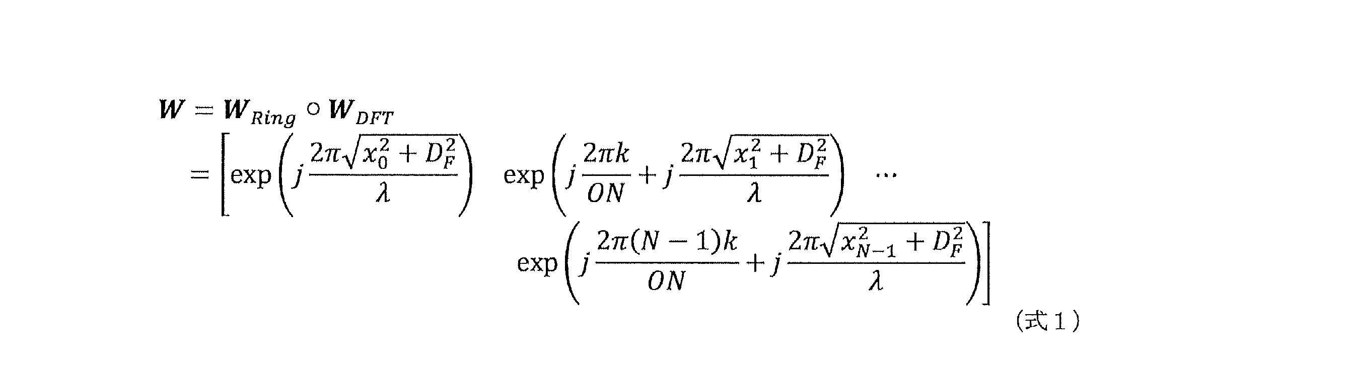
ここで、DFは、アレイと焦点位置の軸方向距離であってもよい。
なお、本開示において、距離依存のプリコーダに係る位相のシフトは、リングタイプ(Ring-Type)位相分布と呼ばれてもよい。また、本開示において、距離依存のプリコーダに係るコードブックは、リングタイプコードブック(Ring-type codebook(RTC))と呼ばれてもよい。
図8は、例1-1-1に係るプリコーダの一例を示す図である。図8では、一様かつ線形のアレイの例が示される。図8に示す例では、まず、ボアサイトにおけるビームフォーカシングが行われる。当該ビームフォーカシングには、上述の距離依存のプリコーダが利用されてもよい。kは、DFTにおいて位相に対応するインデックスである。
図8に示す例において、次いで、DFTベクトルによる焦点位置のシフティングが行われる。当該シフティングには、上述の角度依存のプリコーダが利用されてもよい。
例1-1-1によれば、角度依存項及び距離(位置)依存項を利用することで、遠距離及び近距離の対象に対して適切に信号を送信することができるうえ、実装観点でも容易である。
<例1-1-2>
RISにおけるプリコーダは、DFTベクトルによる区分的線形近似法(piecewise linear approximation with DFT vectors)が利用されるプリコーダであってもよい。
RISにおけるプリコーダは、DFTベクトルによる区分的線形近似法(piecewise linear approximation with DFT vectors)が利用されるプリコーダであってもよい。
例えば、当該プリコーダは、サブアレイ(1つ以上のアレイ)ごとの項及び距離(位置)依存項を含むプリコーダであってもよい。
例1-1-2は、例えば、RISを含むNCR(RIS-NCR)のビームフォーミング/フォーカシング、及び、複数のパネル(例えば、広い間隔で配置されるパネル)のコヒーレント送信、の少なくとも一方に用いられてもよい。
また、例1-1-2は、サブアレイベースのRIS-NCRに適している。
RISにおけるプリコーダは、例えば、サブアレイ(1つ以上のアレイ)ごとのプリコーダと角度依存のプリコーダとの積(例えば、アダマール積(Hadamard product、例えば、要素ごとの積))で算出されてもよい。
サブアレイ(1つ以上のアレイ)ごとのプリコーダは、例えば、サブアレイごとの位相オフセットと、サブアレイの角度オフセットとの積で表されてもよい。
例えば、当該プリコーダは、以下の式2で算出されてもよい。
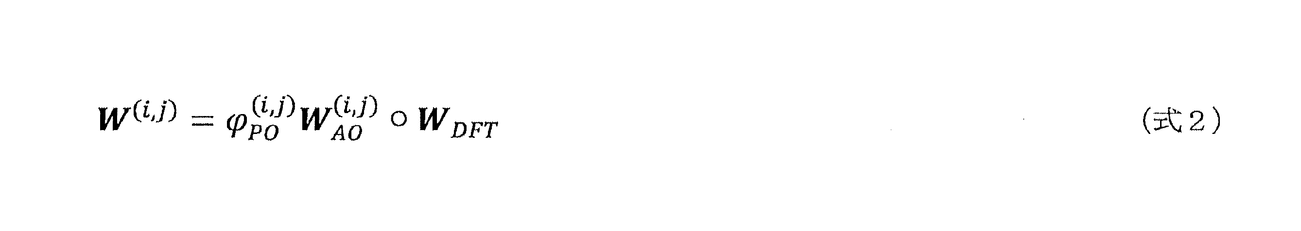
ここで、φ(i,j)
POは、サブアレイ(i,j)の位相オフセットを示してもよい。サブアレイ(i,j)の位相オフセットは、特定の値(例えば、0から2πの値)を取り得る特定のビット(例えば、bビット)で量子化されてもよい。また、W(i,j)
AOは、サブアレイ(i,j)の角度オフセットを示してもよい。
W(i,j)AOは、アレイの参照ポイントからサブアレイ(i,j)の参照ポイントまでのベクトルと、サブアレイ(i,j)の参照ポイントからサブアレイ(i,j)におけるアンテナエレメント(m,n)までのベクトルの内積に基づいて算出されてもよい。
例えば、W(i,j)
AOは、以下の式3で算出されてもよい。
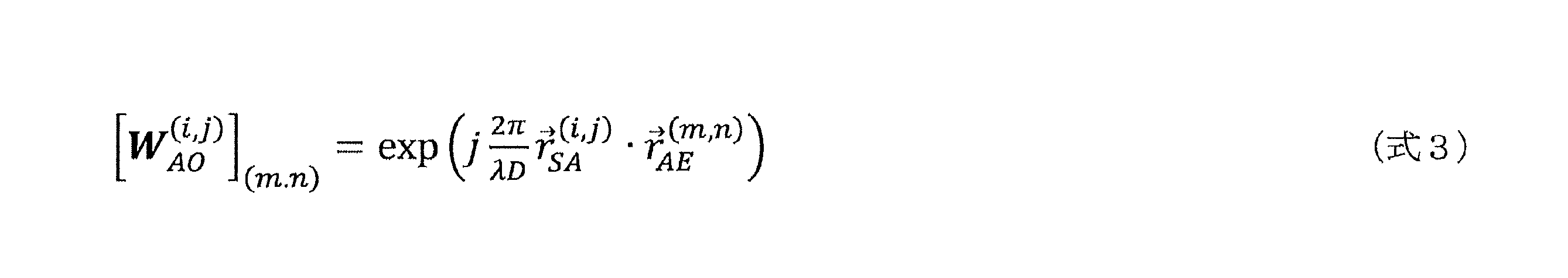
ここで、Dはアレイ(例えば、アレイの参照ポイント)から対象(例えば、UE)までの距離であってもよい。また、r(i,j)
SAはアレイの参照ポイントからサブアレイ(i,j)の参照ポイントまでのベクトルを示し、r(m,n)
AEはサブアレイ(i,j)の参照ポイントからサブアレイ(i,j)におけるアンテナエレメント(m,n)までのベクトルを示してもよい(図9参照)。
図10は、例1-1-2に係るプリコーダの一例を示す図である。図10では、一様かつ線形のアレイの例が示される。図8に示す例では、まず、複数のアレイ(サブアレイごと)について位相オフセットによるビーム方向のフォーカシングが行われる(ステップ1)。当該ビームフォーカシングには、上述の位相オフセット及び角度オフセットに基づくプリコーダが利用されてもよい。
図10に示す例において、次いで、DFTベクトルによる焦点位置のシフティングが行われる(ステップ2)。当該シフティングには、上述の角度依存のプリコーダが利用されてもよい。
例1-1-2によれば、サブアレイ(1つ以上のアレイ)ごとの項及び距離(位置)依存項を利用することで、遠距離及び近距離の対象に対して適切に信号を送信することができる。
<例1-1-3>
RISにおけるプリコーダは、近距離に関する項と遠距離に関する項とが利用されるプリコーダであってもよい。
RISにおけるプリコーダは、近距離に関する項と遠距離に関する項とが利用されるプリコーダであってもよい。
例1-1-3は、例えば、FF及びNFのいずれか又は両方(FF及びNFに限られない)におけるCSIの取得に用いられてもよいし、NFのローカライゼーション/センシングに用いられてもよい。
RISにおけるプリコーダは、例えば、第1のプリコーダと第2のプリコーダとの積(例えば、クロネッカ積(Kronecker product、例えば、要素ごとの積))で算出されてもよい。当該第1/第2のプリコーダは、遠距離(又は、角度依存)に対応する項と、近距離(又は、距離依存)に対応する項と、を含んでもよい。
本例におけるプリコーダは、均一平面アレイ(uniform planar array)において適用されてもよい。
例えば、当該プリコーダWは、以下の式4で表されてもよい。

ここで、Wは、第1のプリコーダであるWN_1,O_1,k_1,D,L_1と第2のプリコーダであるWN_2,O_2,k_2,D,L_2とのクロネッカ積で表される。なお、「N_1」は、「N1」を表す。「N_1」以外の他の表記についても、「N_1」と同様に表す場合がある。
WN_i,O_i,k_i,D,L_iは、例えば、以下の式5で表されてもよい。
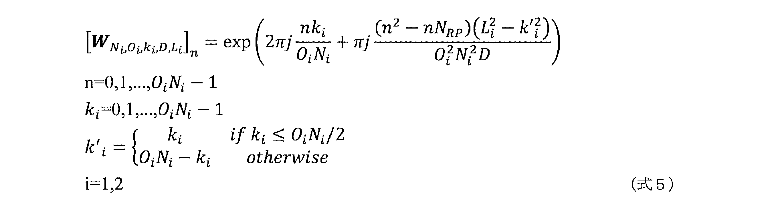
ここで、RISアレイにおけるi番目の軸方向のアンテナ素子(散乱要素)数Niとi番目の軸方向のオーバーサンプリング数Oiとは、既存のNRで規定されるNR DFTベースのコードブックと同じであってもよい。i=1はx軸方向(水平方向)に対応してもよい。i=2はz軸方向(垂直方向)に対応してもよい。また、kiは、コードワードインデックスであり、k’は2次項を表してもよい。
また、NRPは、RISアレイの参照ポイントに依存する値であってもよい。例えば、NRPは、NRP=2(dRP-d0)/Δdで算出されてもよい。
例えば、dRP-d0は特定のアンテナ素子(例えば、アンテナ素子#0)と参照ポイントとの距離を示し、Δdはアンテナ素子間隔を示してもよい。
例えば、アレイの最も左下の素子を参照ポイントとする場合、NRPは0であってもよい。
例えば、アレイの中心座標を参照ポイントとする場合、NRPはNi-1で算出されてもよい。
Dは、参照ポイントと焦点距離との正規化された距離を示してもよい。例えば、Dは、(焦点距離(focal length))/λで算出されてもよい。
Lは、正規化された等価のアパチャー(equivalent aperture)に関する値であってもよい。Lは、例えば、ON・Δd/λで算出されてもよい。
<例1-1-4>
RISにおけるプリコーダは、アクセスリンク(UE及びRIS間)に関するプリコーダとバックホールリンク(BS及びRIS間)に関するプリコーダとが利用されるプリコーダであってもよい。
RISにおけるプリコーダは、アクセスリンク(UE及びRIS間)に関するプリコーダとバックホールリンク(BS及びRIS間)に関するプリコーダとが利用されるプリコーダであってもよい。
例えば、当該プリコーダは、サブアレイ(1つ以上のアレイ)ごとの項及び距離(位置)依存項を含むプリコーダであってもよい。
例1-1-4は、例えば、バックホールリンク/アクセスリンクのRISを含むNCR(RIS-NCR)のビームフォーミング/フォーカシング、及び、カスケードされたLoS-MIMO(例えば、ジョイント焦点指示(joint focal points indication)を要するLoS-MIMO)、の少なくとも一方に用いられてもよい。
RISにおけるプリコーダは、例えば、アクセスリンクに関するプリコーダとバックホールリンクに関するプリコーダとの積(例えば、アダマール積(Hadamard product、例えば、要素ごとの積))で算出されてもよい。
例えば、当該プリコーダは、以下の式6で算出されてもよい。
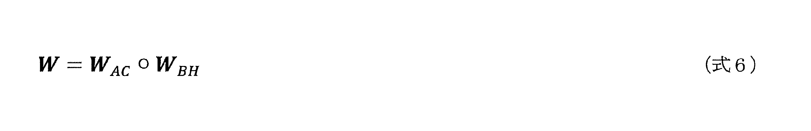
ここで、WACは、RIS-NCRのアクセスリンクにおけるビーム(アクセスビーム、UE向けのビーム)のプリコーダを示してもよい。また、WBHは、RIS-NCRのバックホールリンクにおけるビーム(バックホールビーム、BS向けのビーム)のプリコーダを示してもよい。
WAC及びWBHの少なくとも一方は、例えば、上記例1-1-1から1-1-3に記載される少なくとも1つの方法によって算出されたプリコーダであってもよい。
WAC及びWBHの焦点距離は、それぞれ独立して選択/決定されてもよいし、同時に(jointlyに)選択/決定されてもよい。例えば、WAC及びWBHの焦点距離は、共役対称に選択/決定されてもよい。
例1-1-4によれば、アクセスリンクだけでなく、バックホールリンクにおけるプリコーダ/コードブックの設計を適切に行うことができる。
<コードブック/プリコーダに係る各パラメータ>
以下では、上述の例1-1における各数式のパラメータについて説明する。
以下では、上述の例1-1における各数式のパラメータについて説明する。
Lは、アパチャー(例えば、アンテナ素子)に関するパラメータであってもよい。当該Lは、RIS-NCR(NCR-MT)の能力として報告されてもよい。
Lは、例えば、n次元(例えば、nは2)におけるアンテナ番号(数)/間隔としてRISによって報告されてもよい。
Lは、例えば、RISの辺の長さ(例えば、アンテナ番号×アンテナ間隔)としてRISによって報告されてもよい。
Ni、Oi、ki、kip、Di(i=1又は2)は、アクセスリンク/バックホールリンクのコードブックに関するパラメータであってもよい。
Ni及びOiは、RISのコードブックに関連してもよい。当該RISのコードブックは予めRISに対し設定されてもよいし、仕様で予め規定されてもよい。
Ni及びOiは、RISの能力に関する報告に基づいて決定されてもよいし、RISの次元とは無関係に決定されてもよい。
kiは、RISのコードブックに関連してもよい。当該RISのコードブックはRISに対し指示されてもよい。
kipは、RISに対する特定の設定/指示に基づいてRISにおいて算出されてもよい。
Di(例えば、i=1)はBSとRIS間の距離に関するパラメータであってもよい。Di(例えば、i=2)はUEとRIS間の距離に関するパラメータであってもよい。
例えば、D1は、RISに対しBSによって予め設定されてもよいし、D2は、RISに対しBSによって指示されてもよい。
例えば、D1及びD2は、BSによって(単一のCW(compound CW)を用いて)指示されてもよい。
例えば、D1は、RISに対しBSによって予め設定されてもよいし、D2は、RISによって測定されてもよい。
例えば、D1及びD2は、RISによって測定されてもよい。
例えば、D1及びD2の決定に、対数量子化(logarithmicquantization)が用いられてもよい。
NRPは、RISの参照ポイントに関するパラメータであってもよい。NRPは、例えば、RISの参照ポイントのオフセットに関するパラメータであってもよい。
NRPは、RISのコードブックに関連してもよい。当該RISのコードブックはRISに対し指示されてもよい。
RISの参照ポイントは、特定の位置を意味してもよい。
例えば、RISの参照ポイントは、特定の位置(例えば、最も左下)のアンテナ/サブアレイの位置であってもよい。
例えば、RISの参照ポイントは、RISの中心点の位置であってもよい。この場合、単一の大型RIS、又は、複数の分離したサブアレイに適している。
例えば、RISの参照ポイントが、RISが報告してもよい。RISの参照ポイントは、RISによって報告される参照ポイントに従って決定されてもよい。
アダプテーション(アパチャーアダプテーション)モードを示すパラメータが規定されてもよい。当該パラメータは、RISのアパチャー制御に用いられてもよい。
アダプテーションモードを示すパラメータは、RISのコードブックと関連してもよい。当該RISのコードブックは、RISに対して指示されてもよい。
RISの形状/サイズを示すパラメータが規定されてもよい。当該パラメータは、RISのアパチャー制御に用いられてもよい。
RISの形状/サイズを示すパラメータは、RISのコードブックと関連してもよい。当該RISのコードブックは、RISに対して指示されてもよい。
当該パラメータは、ビットマップで指示されてもよい。また、当該パラメータは、平行四辺形を形成するアパチャーの2辺の方向及び長さによって指示されてもよい。また、当該パラメータは、サブアレイの配置(例えば、方向/間隔/サブアレイ番号/サブアレイの大きさ)によって指示されてもよい。また、当該パラメータは、平行四辺形を形成するアパチャーの2辺の方向/長さ(general modeと呼ばれてもよい)、サブアレイ番号(サンプリングレート)、及び、サブアレイサイズ、の少なくとも1つによって指示されてもよい。
ロールオフファクタを示すパラメータが規定されてもよい。
共役対称(conjugate symmetric)のRTCに関するパラメータが規定されてもよい。当該パラメータは、UEの位置に関する参照ポイントに関するパラメータであってもよい。
UEの位置に関する参照ポイントは、例えば、特定のUEのアンテナポート(例えば、アンテナポート#0)を意味してもよい。
UEの位置に関する参照ポイントは、例えば、BSによって設定された特定の(例えば、中心の)UEアレイを意味してもよい。
<例1-2>
例1-2では、(NW/RIS-NCRに対する)コードブックの通知における、角度(角度情報)及び距離(距離情報)についての量子化について説明する。
例1-2では、(NW/RIS-NCRに対する)コードブックの通知における、角度(角度情報)及び距離(距離情報)についての量子化について説明する。
例1-2は、例1-2-1及び1-2-2に大別される。下記例1-2-1及び1-2-2のいずれかが適用されてもよいし、下記例1-2-1及び1-2-2が組み合わされて適用されてもよい。
NW(又は、RIS-NCR)は、RIS-NCR(又は、NW)に対し、例1-2-1及び1-2-2の少なくとも一方を用いて量子化されたコードブック/プリコーダに関する角度情報/距離情報を送信してもよい。
<例1-2-1>
角度に関する量子化と、距離に関する量子化と、が別々に(独立して)行われてもよい。
角度に関する量子化と、距離に関する量子化と、が別々に(独立して)行われてもよい。
角度については、特定の量子化方法が用いられてもよい。当該特定の量子化方法は、例えば、DFTベース(DFT-based)の量子化方法であってもよい。角度の量子化についてDFTベースを用いることで、FF及びNFについて統一した設計に適し量子化を行うことができる。
例えば、距離については、線形量子化が用いられてもよい。線形量子化を用いることで、装置における実装が容易となる。例えば、距離については、対数量子化が用いられてもよい。対数量子化を用いることで、装置間の距離が遠距離/近距離に関わらず、適切な量子化を行うことができる。
距離についての量子化は、以下の式7を用いて行われてもよい。

本開示において、NFの範囲は、アレイ面積と関連してもよい。例えば、NFの範囲は、アレイ面積と(ほぼ)比例してもよい。
<例1-2-2>
角度に関する量子化と、距離に関する量子化と、がジョイントして行われてもよい。
角度に関する量子化と、距離に関する量子化と、がジョイントして行われてもよい。
例えば、角度及び距離に関する量子化は、直交座標(Cartesiancoordinates)における一様な(uniform)グリッドを用いてもよい(角度及び距離は、一様なグリッド上に量子化されてもよい)。この場合、ローカライゼーション/ポジションベースのビームフォーカシングにおいて好適に利用できる。
例えば、角度及び距離に関する量子化は、球面座標(sphericalcoordinates)における非一様な(non-uniform)グリッドを用いてもよい(角度及び距離は、非一様なグリッド上に量子化されてもよい)。この場合、ボアサイトにおけるアパチャー/NFレンジ観点で好適であるとともに、近距離においてより広いビームを使用することで、より均一なカバレッジとビーム数の削減とを実現することができる。
例えば、角度及び距離に関する量子化は、以下の式8を用いて行われてもよい。
図11は、直交座標における一様なグリッドの一例を示す図である。図11に示す例では、RIS(RIS-NCR)に対する直交座標の一様なグリッドが示される。
図11において、(xgi,ygi,zgi)は、グリッドインデックスiから得られたi番目のグリッドの中心座標を示してもよい。
一様な(uniform)グリッドを用いるRTC(uniform grid RTC)は、以下の選択肢1及び2の少なくともいずれかによって算出されてもよい。
一様なグリッドを用いるRTCは、以下の式9を用いて算出されてもよい(選択肢1)。

一様なグリッドを用いるRTCは、以下の式10を用いて算出されてもよい(選択肢2)。
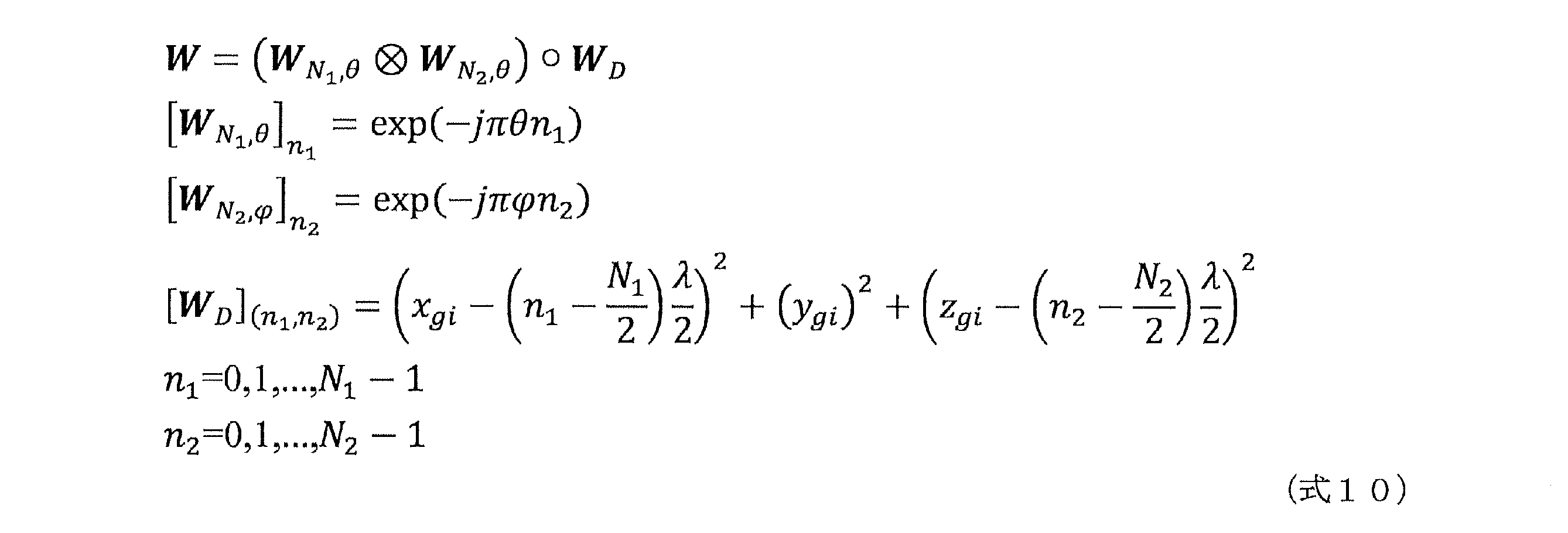
ここで、上記θは以下の式11を用いて算出されてもよい。
ここで、μは方位角、νは仰角、のそれぞれを表してもよい。μ及びνは、特定の座標変換によって得られてもよい。
例1-2によれば、コードブックの通知における、角度(角度情報)及び距離(距離情報)についての量子化を適切に行うことができる。
<関連技術の第2の例>
第2の例は、RISにおけるアパチャーのアダプテーションに関する。
第2の例は、RISにおけるアパチャーのアダプテーションに関する。
第2の例は、例2-1及び2-2に大別される。下記例2-1又は2-2が適用されてもよいし、下記例2-1及び2-2が組み合わされて適用されてもよい。
RIS-NCRは、NWから、アパチャー(例えば、アンテナ素子)の制御に関する情報(設定情報)を受信してもよい。RIS-NCRは、当該情報に基づいて、端末向けの信号に用いるアパチャー/アンテナ素子を決定してもよい。
<例2-1>
RIS(RIS-NCR)は、RISに含まれるアパチャーのうち、使用するアパチャーを選択/決定/判断してもよい。
RIS(RIS-NCR)は、RISに含まれるアパチャーのうち、使用するアパチャーを選択/決定/判断してもよい。
例2-1は、例2-1-1及び2-1-2に大別される。下記例2-1-1又は2-1-2が適用されてもよいし、下記例2-1-1及び2-1-2が組み合わされて適用されてもよい。
<例2-1-1>不要なRISの素子(例えば、アンテナ素子)がオフに設定されてもよい。当該設定に関する情報は、NWから受信するアパチャーの制御に関する情報に含まれてもよい。
不要なRISの素子は、入射信号を散乱(又は、反射/屈折)しないよう構成されてもよい。また、不要なRISの素子は、入射信号を拡散、又は、ランダムに散乱(又は、反射/屈折)するよう構成されてもよい。
<例2-1-2>
ビームフォーミングとアパチャーアダプテーションが組み合わされて用いられてもよい。
ビームフォーミングとアパチャーアダプテーションが組み合わされて用いられてもよい。
当該ビームフォーミングに関する情報は、例えば、RISのビームフォーミングベクトルに関する情報を含んでもよい。
例えば、(所望の(desired)、実際に使用される)アパチャーは、各RIS素子のオン/オフ状態を示す値(例えば、アパチャー関数)で表されてもよい。加えて、(所望の(desired)、実際に使用される)アパチャーは、当該RISのビームフォーミングベクトルに適用されてもよい。
例えば、RIS素子に対応する値(例えば、アパチャー関数)が第1の値(例えば、0)の場合、当該RIS素子はオフ状態とすることを示してもよい。また、例えば、RIS素子に対応する値(例えば、アパチャー関数)が第2の値(例えば、1)の場合、当該RIS素子はオン状態とすることを示してもよい。
アパチャーアダプテーションは、ビーム形状(例えば、ビーム幅、サイドローブ、メインローブ、及び、焦点の形状/サイズの少なくとも1つ)を制御するために用いられてもよい。
<例2-2>
例2-2では、RIS(RIS-NCR)におけるアパチャーの制御について説明する。
例2-2では、RIS(RIS-NCR)におけるアパチャーの制御について説明する。
例2-2は、例2-2-1及び2-2-2に大別される。下記の例2-2-1又は2-2-2が適用されてもよいし、下記の例2-2-1及び2-2-2が組み合わされて適用されてもよい。
<例2-2-1>
RIS-NCRのアパチャーに関するモードが規定されてもよい。
RIS-NCRのアパチャーに関するモードが規定されてもよい。
RIS-NCRは、当該モードに基づいて、使用するアパチャーを判断してもよい。当該モードは、例えば、第1から第3のモードを含んでもよい。
第1のモードは、RISの素子の一部/全部を正方形状に使用するモードであってもよい。第1のモードは、例えば、フォールバックモードと呼ばれてもよい。
第2のモードは、例えば、RISの素子の一部を平行四辺形(ひし形)状に使用するモードであってもよい。第2のモードは、例えば、半連続モード(semi-continuous mode)と呼ばれてもよい。
第3のモードは、RISの素子のうち、特定のRISのみを使用するモードであってもよい。当該特定のRISは、RISの素子の一部を平行四辺形(ひし形)状に選択し、その中から決定されてもよい。第3のモードは、例えば、離散的モード(discrete mode)と呼ばれてもよい。
<例2-2-2>
使用されるRIS-NCRのアパチャーの形状/サイズが特定の方法によって指示されてもよい。当該指示に関する情報は、NWから受信するアパチャーの制御に関する情報に含まれてもよい。
使用されるRIS-NCRのアパチャーの形状/サイズが特定の方法によって指示されてもよい。当該指示に関する情報は、NWから受信するアパチャーの制御に関する情報に含まれてもよい。
例えば、使用されるRISの素子のオン/オフ状態を示すビットマップ/パラメータによって、使用されるRIS-NCRのアパチャーの形状/サイズが決定されてもよい。
上記第2/第3のモードにおけるアパチャー(例えば、平行四辺形(ひし形)状のアパチャー)の形状/サイズが、特定の方法で示されてもよい。当該特定の方法は、例えば、RISの素子(選択されるRISの素子)の特定のポイント(例えば、参照ポイント)を基準とする2辺の長さ及び角度に基づく方法であってもよい。
上記第3のモードでは、使用されるサブアレイのサイズ/個数を追加で示されてもよい。
以上第2の例によれば、使用するRISの素子/アパチャーを適切に決定/選択することができる。
<本実施の形態の検討事項>
制御チャネル(例えば、SSB等)を転送する場合、以下の2つの検討事項が生じる事で、コードブックから生成されたUE固有のビームが非実用的となり、採用が困難となる。
制御チャネル(例えば、SSB等)を転送する場合、以下の2つの検討事項が生じる事で、コードブックから生成されたUE固有のビームが非実用的となり、採用が困難となる。
1つ目は、RISのアパチャー(aperture)は大きいため、UE固有のビームフォーミング(UE-specific beamforming)のビーム幅が狭くなり、広いエリアを効果的にカバーすることが困難となるという事項である。
広いエリアを効果的にカバーできない場合、上述した既存の方法のように、SSBリソースの大幅な割り当てを必要とするか、あるいは、SSBのスキームへの大幅な変更が必要となってしまう。SSBリソースの割り当てが増大した場合、相対的に、他のチャネル(又は信号)へのリソースの割り当てが減少してしまい、システム全体のスループットの低下、リソースの利用効率の低下につながってしまう。SSBのスキームへの大幅な変更が生じた場合、gNB及び/又はUEにおいても、大幅な変更が生じてしまうために、バージョンの間等での互換性を保つことが困難となってしまう。
2つ目は、既存のスキームでは、gNBが転送のためにRISに対して送るために、かなりの数のSSBを利用する必要がある一方で、SSBの合計の可用性(例えば、SSBの使用可能なリソースの数等)は制限されるという事項である。例えば、0.64m四方のサイズを有し、30GHzにて使用されるRISが、近傍界及び遠方界を含む±45°の範囲をカバーするケースでは、おおよそ、300個のナロービーム(narrow beam)が要求される。なお、この場合、ナロービームの3dBのビーム幅が0.79°である。
例えば、SSBを利用する数が増加した場合、相対的に、他のチャネル(又は信号)へのリソースの割り当てが減少してしまい、システム全体のスループットの低下、リソースの利用効率の低下につながってしまう。また、SSBの合計の制限を変更(例えば、緩和)することが考えられるが、そのような制限を変更した場合、gNB及び/又はUEにおいても、変更が生じてしまうために、バージョンの間等での互換性を保つことが困難となってしまう。
このように、コードブックによって指示されるUE固有のビームのビーム幅が、非常に狭いため、エリアを直接カバーするのは困難であるという事項と、RISがナロービームを使用してSSBを転送する場合、限られたSSBリソースのかなりの部分が消費されてしまうという事項とを鑑み、本実施の形態では、ワイドビーム(wide beam)の生成を検討する。
例えば、本実施の形態では、RISのワイドビーム生成のためのコードブックベースの指示方法を説明する。また、本実施の形態では、例示的に、ワイドビームに基づいて制御チャネルの転送方法を説明する。
なお、或る機能(又は動作)の「指示」は、当該機能(又は動作)を行うための情報を示してもよいし、当該機能(又は動作)を行うための情報の送信(又は通知)等の動作を示してもよい。なお、「指示」は、インジケーション、インジケータ、情報、パラメータ等に置き換えられてもよい。例えば、ビーム指示は、ビーム制御を行うための情報を示してもよいし、ビーム制御を行うための情報の送信(又は通知)等の動作を示してもよい。
<提案の概要>
以下の提案では、ビーム生成に関する制御情報の選択に基づく、近傍界でのワイドビームの生成を説明する。ビーム生成に関する制御情報とは、例えば、RTCの中に含まれるコードワード(以下、RTCコードワードと記載する)であってよい。RTCは、追加の特殊なコードワード生成を必要とせずに、ワイドビーム生成を可能にする。また、RISによりあらゆる形状のワイドビームを生成できる。
以下の提案では、ビーム生成に関する制御情報の選択に基づく、近傍界でのワイドビームの生成を説明する。ビーム生成に関する制御情報とは、例えば、RTCの中に含まれるコードワード(以下、RTCコードワードと記載する)であってよい。RTCは、追加の特殊なコードワード生成を必要とせずに、ワイドビーム生成を可能にする。また、RISによりあらゆる形状のワイドビームを生成できる。
近傍界でのワイドビーム生成のためのRTCコードワード選択のメカニズムとして、コードワード選択は、RISとターゲットエリアとの間の幾何学的関係(geometric relationship)に基づいて行われてよい。例えば、ターゲットエリアの寸法(dimension)、角度、及び、ターゲットエリアの中心とRISアレイの中心との間の距離の3つのパラメータのうち少なくとも1つによって、RTCコードワードが選択されてよい。
<提案1:コードワード選択>
提案1では、RTCコードワード選択に基づく近傍界ワイドビーム生成を説明する。例示的に、幾何光学原理(geometric optics principle)に基づいて、ワイドビームに対応する焦点位置が決定される。
提案1では、RTCコードワード選択に基づく近傍界ワイドビーム生成を説明する。例示的に、幾何光学原理(geometric optics principle)に基づいて、ワイドビームに対応する焦点位置が決定される。
コードワード選択のステップ1では、RISとターゲットエリアとの間の幾何学的関係に基づいて焦点の位置が算出される。焦点の位置は、以下では、焦点位置または焦点と記載される場合がある。
図12Aは、焦点位置の算出の第1の例を示す図である。図12Bは、焦点位置の算出の第2の例を示す図である。図12A、図12Bにおいて、面Dは、RISアレイの面を示し、面Lはターゲットエリアを示す。なお、RISアレイは、RISからの信号(又は電波)が放射される放射面の一例であってよい。距離dは、面Dの中心及び面Lの中心の間の距離を示す。角度αは、面Dと、面Dの中心及び面Lの中心を結ぶ直線に対して垂直な面との間の角度を示す。角度βは、面Lと、面Dの中心及び面Lの中心を結ぶ直線に対して垂直な面との間の角度を示す。また、図12Aにおいて、距離Fは、面Dの中心と実際の焦点位置Pとの間の距離を示し、図12Bにおいて、距離Fは、面Dの中心と仮想の焦点位置Pとの間の距離を示す。以下、焦点位置とRISアレイ(つまり、面D)との間の距離Fは、焦点距離と称される場合がある。
図12Aに示すように、焦点位置として、実際の焦点位置が算出されてもよい。図12Aの場合、面Dの中心から焦点位置Pまでの距離Fは、式(12)によって表される。
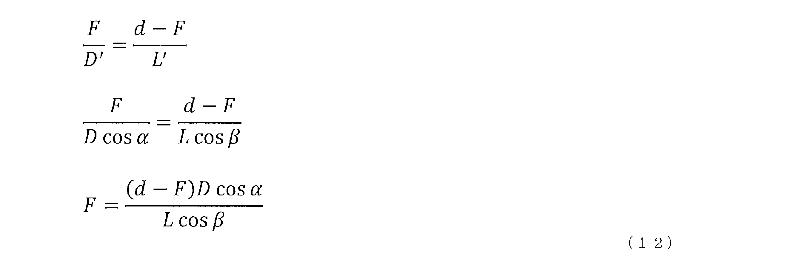
そして、距離Fが算出された場合、面Dの中心(つまり、RISアレイの中心)から垂直に、面Lの方向(つまり、ターゲットエリアの方向)に距離F離れた位置が、実際の焦点位置に決定される。
式(12)に表されるように、RISアレイとターゲットエリアとの間の幾何学的関係の例として、RISアレイの位置及びサイズと、ターゲットエリアの位置及びサイズと、RISアレイとターゲットエリアとの位置関係によって決定される角度差等によって、焦点位置が算出される。
また、図12Bに示すように、焦点の位置として、仮想の焦点位置が算出されてもよい。図12Bの場合、面Dの中心から焦点位置Pまでの距離Fは、式(13)によって表される。
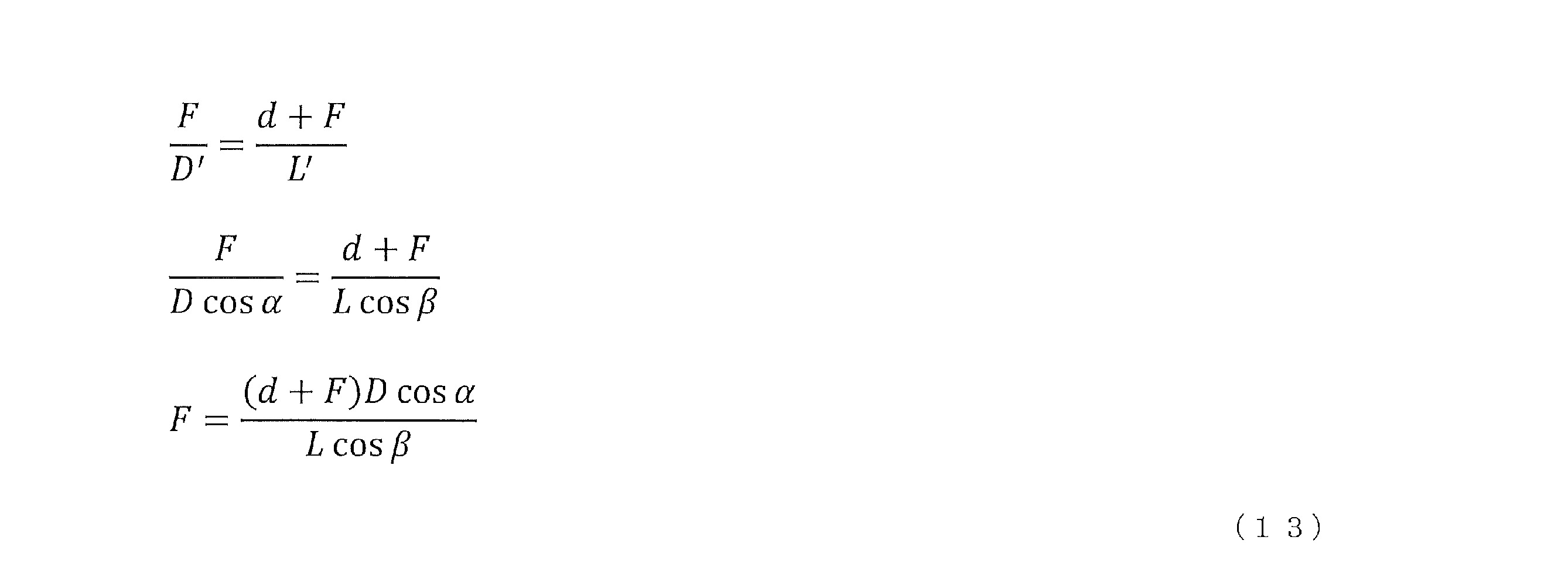
そして、距離Fが算出された場合、面Dの中心(つまり、RISアレイの中心)から垂直に、面Lの方向と反対の方向(つまり、ターゲットエリアの方向と反対の方向)に距離F離れた位置が、仮想の焦点位置に決定される。
式(13)に表されるように、RISアレイとターゲットエリアとの間の幾何学的関係の例として、RISアレイの位置及びサイズと、ターゲットエリアの位置及びサイズと、RISアレイとターゲットエリアとの位置関係によって決定される角度差等によって、焦点位置が算出される。
なお、実際の焦点位置を算出するか、または、仮想の焦点位置を算出するかは、仕様によって規定されてもよいし、ネットワークからの指示によって決定されてもよい。実際の焦点位置を算出するか、または、仮想の焦点位置を算出するかは、動的に切り替えられてもよいし、固定されてもよい。
コードワード選択のステップ2では、算出した焦点位置に従って(基づいて)、RTCコードワードが選択される。例えば、焦点が算出した焦点位置に一致(又は近接)するような電波の放射が達成されるRTCコードワードが選択される。なお、焦点位置に従って、RTCコードワードが選択される代わりに、焦点距離Fに従って、RTCコードワードが選択されてもよい。
なお、選択の方法については、特に限定されない。例えば、焦点位置とRTCコードワードが対応づけられており、その対応関係に基づいて、RTCコードワードが選択されてもよい。あるいは、焦点位置または焦点位置の算出に用いたパラメータに対する特定の演算処理によって、RTCコードワードを示す情報(例えば、コードワードに対応づけられたインデックス)が算出され、算出された情報に基づいて、RTCコードワードが選択されてもよい。また、焦点位置は量子化され、量子化後の焦点位置に対応づけられるRTCコードワードが選択されてもよい。また、焦点位置は、有限個のグループの何れかに分類され、分類されたグループに対応するRTCコードワードが選択されてもよい。
なお、焦点位置(又は焦点距離)に応じて、選択するコードワードが変更されてもよい。例えば、焦点位置(又は焦点距離)が所定の範囲内である場合、ターゲットエリアが近傍界の範囲内であると判定され、RTCコードワードが選択されてもよい。また、例えば、焦点位置(又は焦点距離)が所定の範囲内ではない場合、ターゲットエリアが遠方界の範囲内であると判定され、遠方界でのビーム生成のためのコードワード(例えば、DFTコードブックのコードワード)が選択されてもよい。
また、上述したステップ1及びステップ2の処理は、RISによって実行されてもよいし、少なくとも1つがRISによって実行され、残りがネットワーク(例えば、gNB)によって実行されてもよい。例えば、RISが実行する処理に関するパラメータは、ネットワークから提供されてもよい。あるいは、2つの処理の両方がネットワークによって実行され、RISは、選択されたRTCコードワードの指示を受けて、ワイドビームを生成してもよい。
図12Cは、生成されるワイドビームの一例を示す図である。図12Cには、gNBから送信されたSSB#Nが、RISによって転送されることが示される。図12Cに示すように、提案1によれば、ターゲットエリアをカバーするワイドビームを生成して、SSB#Nを送信できる。
上述した提案1では、RISアレイとターゲットエリアとの間の幾何学的関係に基づいて算出した焦点位置に従ってRTCコードワードを選択することによって、ターゲットエリアをカバーする近傍界のワイドビームのためのRTCコードワードを適切に選択できる。例えば、焦点位置が、面D(放射面)と、面L(ターゲットエリア)との間、又は、面Dを挟んで、面Lとは反対側の領域に設定されるように、RTCコードワードが選択される。そのため、近傍界のワイドビームを適切に生成できる。
<提案2>
提案2では、ワイドビームのシェイピング(shaping)の方法の例を説明する。なお、ワイドビームのシェイピングは、ワイドビームによってカバーするターゲットエリアの形状に基づく、ワイドビームの形状の制御であってよい。提案2では、ワイドビームのシェイピングの例として、マルチワイドビームの生成、RISの動作モードの制御、及び、位相マスクについて説明する。
提案2では、ワイドビームのシェイピング(shaping)の方法の例を説明する。なお、ワイドビームのシェイピングは、ワイドビームによってカバーするターゲットエリアの形状に基づく、ワイドビームの形状の制御であってよい。提案2では、ワイドビームのシェイピングの例として、マルチワイドビームの生成、RISの動作モードの制御、及び、位相マスクについて説明する。
<提案2-1:マルチワイドビームの生成>
図13は、マルチワイドビーム生成の一例を示す図である。図13には、ターゲットエリア#1とターゲットエリア#2の2つのターゲットエリアに対してビームを生成するRISの例が示される。
図13は、マルチワイドビーム生成の一例を示す図である。図13には、ターゲットエリア#1とターゲットエリア#2の2つのターゲットエリアに対してビームを生成するRISの例が示される。
マルチワイドビームの生成のステップ1では、RISとターゲットエリアとの間の幾何学的関係に基づいて焦点位置が算出される。焦点位置の算出方法は、上述した提案1と同様であってもよい。ただし、提案2-1では、図13に示すように、複数のターゲットエリアのそれぞれについて、焦点位置が算出される。
マルチワイドビームの生成のステップ2では、RISは、ターゲットのビーム形状に応じてワイドビームのRTCコードワードを複数選択する。図13の例では、RISは、ターゲットエリア#1に対する焦点#1に従って、ターゲットエリア#1をカバーするビーム形状に応じたRTCコードワード#1を選択する。同様に、図13の例では、RISは、ターゲットエリア#2に対する焦点#2に従って、ターゲットエリア#2をカバーするビーム形状に応じたRTCコードワード#2を選択する。
なお、1つの焦点に対する1つのRTCコードワードの選択の選択方法については特に限定されない。例えば、上述した提案1と同様に1つの焦点に対する1つのRTCコードワードが選択されてもよい。
マルチワイドビームの生成のステップ3では、RISは、選択したコードワードの複素重ね合わせ(complex superposition)を行い、マルチビームコードワードを取得する。図13の例では、RTCコードワード#1と、RTCコードワード#2との複素重ね合わせを行って、マルチビームコードワードを取得する。なお、マルチビームコードワードは、複数のビームを生成するコードワードであってよい。また、複数のワイドビームを生成するコードワードは、マルチワイドビームコードワードと称されてもよい。
例えば、n個(nは1以上の整数)のワイドビームコードワードから得られるマルチワイドビームコードワードは、次の式(14)によって表される。なお、n個のワイドビームコードワードは、n個のターゲットエリアに対応してもよいし、n個の焦点位置に対応してもよい。

ここで、wmultiは、マルチビームコードワードであり、w1、・・・、wnはn個のワイドビームコードワード(例えば、RTCコードワード)であり、a1、・・・、anは、パワー割当要素である。
上述した提案2-1によれば、ターゲットエリアが複数存在した場合でも、それらのターゲットエリアをカバーするマルチワイドビームを形成できる。
また、上述したステップ1~ステップ3の処理は、RISによって実行されてもよいし、少なくとも1つがRISによって実行され、残りがネットワーク(例えば、gNB)によって実行されてもよい。あるいは、3つの処理のそれぞれがネットワークによって実行され、RISは、選択されたRTCコードワードの指示を受けて、マルチワイドビームを生成してもよい。
なお、上述したステップ2では、複数の焦点位置に対応する複数のコードワードを選択し、ステップ3において、複数のコードワードを重ね合わせてマルチワイドビームコードワードを算出する例を示したが、本開示はこれに限定されない。例えば、複数の焦点位置と、複数の焦点位置に対応する1つのマルチワイドビームコードワードとが、対応づけられて記憶されてもよい。この場合、ステップ3のような重ね合わせの演算処理を行うことなく、対応関係に基づいて、マルチワイドビームコードワードが選択される。この場合、1つの焦点位置に対応するワイドビームコードワードと、複数の焦点位置に対応するマルチワイドビームコードワードとが、併せて記憶されてもよい。
また、提案2-1においては、ステップ2において選択したワイドビームコードワード(例えば、RTCコードワード)と、ステップ3において算出したマルチワイドビームコードワードとが、切り替えられてもよい。例えば、ターゲットエリア#1に向けてワイドビームを生成する場合と、ターゲットエリア#2に向けてワイドビームを生成する場合と、ターゲットエリア#1と#2との両方に向けてマルチワイドビームを生成する場合とで、コードワードが切り替えられてもよい。
<提案2-2:RISの動作モードの制御>
RISアレイ内の或る1つ以上のエレメントの動作モードを選択的に修正することによって、ワイドビームシェイピングが実現されてよい。例えば、特定のエレメントの動作モードを、反射モードから吸収モードに切り替えることによって、ワイドビームシェイピングが実現されてよい。
RISアレイ内の或る1つ以上のエレメントの動作モードを選択的に修正することによって、ワイドビームシェイピングが実現されてよい。例えば、特定のエレメントの動作モードを、反射モードから吸収モードに切り替えることによって、ワイドビームシェイピングが実現されてよい。
なお、RISの動作モードの制御には、主に、以下の動作のモードが含まれる。
・反射(reflection)
・屈折(refraction)
・吸収(absorption)
・散乱(scattering)
・変調(modulation)
・透過(transparent)
・反射(reflection)
・屈折(refraction)
・吸収(absorption)
・散乱(scattering)
・変調(modulation)
・透過(transparent)
上述した提案2-2によれば、ターゲットエリアの形状が変更した場合でも、一部のエレメントの動作モードを変更するという処理によって、変更後のターゲットエリアをカバーするワイドビームを形成できる。これにより、ターゲットエリア外への不要放射を抑制できるため、ターゲットエリア外へ干渉が生じることが回避でき、電力消費も抑制できる。
<提案2-3:位相マスク>
RISエレメントのサブセットに、ランダムな位相マスクを組み込むことによって、ワイドビームシェイピングが実現されてよい。
RISエレメントのサブセットに、ランダムな位相マスクを組み込むことによって、ワイドビームシェイピングが実現されてよい。
上述した提案2-3によれば、ターゲットエリアの形状が変更した場合でも、一部のエレメントの動作モードを変更するという処理によって、変更後のターゲットエリアをカバーするワイドビームを形成できる。これにより、ターゲットエリア外への不要放射を抑制できるため、ターゲットエリア外へ干渉が生じることが回避でき、電力消費も抑制できる。
なお、上述した提案2-1~提案2-3は、組み合わせて用いられてもよいし、相互に切り替えられて用いられてもよい。例えば、提案2-1を用いて、複数のターゲットエリアに向けてマルチワイドビームを生成し、提案2-2及び/又は提案2-3を用いて、ターゲットエリアの形状に基づいてワイドビームの形状を変更してもよい。
<提案3>
提案2では、3つのワイドビームシェイピングの方法を示した。提案3では、特に、長方形のカバレージエリア用に設計されたワイドビームシェイピングの方法を示す。
提案2では、3つのワイドビームシェイピングの方法を示した。提案3では、特に、長方形のカバレージエリア用に設計されたワイドビームシェイピングの方法を示す。
図14は、提案3の一例を示す図である。図14には、RISと、長方形のターゲットエリア#3とが示される。
1次元のRTCからコードワードを選択して組み合わせることによって、任意のアスペクト比の長方形のエリアをカバーできる。
ステップ1では、RISは、RISの2つの方向(例えば、次元)を、ターゲットエリアの水平方向および垂直方向に合わせる。次に、幾何光学の原理に基づいて、1次元のワイドビームの焦点#1が、水平方向について算出され、1次元のワイドビームの焦点#2が、垂直方向について算出される。
ステップ2では、式(15)のように、対応する1次元のRTCコードワードのクロネッカー積を計算して、ワイドビームコードワードを取得する。

式(15)において、wwideは、2次元のワイドビームコードワードを示し、w1及びw2は、それぞれ、水平方向及び垂直方向の1次元のRTCコードワードを示し、式(15)は、w1とw2とのクロネッカー籍によってwwideが得られることを示す。
上述した提案3によれば、ターゲットエリアの拡大、縮小、形状の変更等を行うことができるため、カバレッジの制御を柔軟に行うことができる。これにより、ターゲットエリア外への不要放射を抑制できるため、ターゲットエリア外へ干渉が生じることが回避でき、電力消費も抑制できる。
なお、提案3では、長方形のカバレージエリア用に設計されたワイドビームシェイピングの方法について示したが、本開示はこれに限定されない。長方形以外の任意の形状に対して、ワイドビームシェイピングが行われてもよい。例えば、RISアレイの形状が長方形であり、ターゲットエリアが正方形である場合、提案3と同様の方法にて、ターゲットエリアの形状に基づいたワイドビームシェイピングが行われてもよい。また、例えば、RISアレイの形状が円であり、ターゲットエリアが楕円である場合、提案3と同様の方法にて、ターゲットエリアの形状に基づいたワイドビームシェイピングが行われてもよい。
なお、提案3と提案2とは組み合わせて用いられてもよい。例えば、提案2―1と提案3との組み合わせにより、長方形のターゲットエリアをカバーするワイドビームが、複数の長方形のターゲットエリアに対して生成されてもよい。また、提案2-2又は提案2-3と提案3との組み合わせにより、長方形の一部が欠けたような形状のターゲットエリアをカバーするワイドビームが生成されてもよい。
<補足>
上述した各提案において用いられるワイドビームについて補足する。
上述した各提案において用いられるワイドビームについて補足する。
例えば、同じサイズのRISアレイにおいて、集束ビーム(focused beam)とワイドビームとが生成された場合、集束ビームは相対的に高いSNRを達成でき、ワイドビームは特定のエリアを効果的にカバーできる。そのため、集束ビームは、データチャネルの送信に適し、ワイドビームは制御チャネルの送信に適する。ただし、集束ビームを用いて、データチャネル以外のチャネル(例えば、制御チャネル、ブロードキャストチャネル等)が送信されてもよいし、データチャネルに配置される信号以外の信号が送信されてもよい。また、ワイドビームを用いて、制御チャネル以外のチャネル(例えば、データチャネル、ブロードキャストチャネル等)が送信されてもよいし、制御チャネルに配置される信号以外の信号が送信されてもよい。
例えば、或るサイズを有するRISアレイ#1と、RISアレイ#1のサイズの2倍のサイズを有するRISアレイ#2とが、或るカバレッジエリアに対するワイドビームを生成した場合、RISアレイ#2のワイドビームのSNRのゲインは、RISアレイ#1のSNRのゲインよりも、3dB程度大きい。同様に、RISアレイのサイズが4倍になった場合、ワイドビームのSNRのゲインは6dB程度増加する。
例えば、或るサイズを有するカバレッジエリア#1と、カバレッジエリア#1のサイズの2倍のサイズを有するカバレッジエリア#2とに対して、RISアレイがワイドビームを生成した場合、カバレッジエリア#2におけるワイドビームのSNRのゲインは、カバレッジエリア#1におけるSNRのゲインよりも、1.5dB程度小さい。同様に、カバレッジエリアが4倍になった場合、ワイドビームのSNRのゲインは、3dB程度減少する。
上述したように、例えば、カバレッジエリアのサイズ、RISアレイのサイズ、及び、ワイドビームのSNRのゲインは、特定の関係を示す。そのため、カバレッジエリアのサイズ、RISアレイのサイズ、及び、ワイドビームのSNRのゲインの少なくとも1つに応じて、他の2つが設定されてもよい。例えば、所望のSNRのゲインに応じて、カバレッジエリアのサイズとRISアレイのサイズの少なくとも一方が設定されてもよいし、所望のSNRのゲインと所望のカバレッジエリアのサイズとに応じて、RISアレイのサイズが設定されてもよい。
マルチワイドビーム生成に基づく方法は、RISエレメントのそれぞれからのビームフォーミングゲインを利用して、ビームシェイピング用に用いられてもよい。マルチワイドビーム生成に基づくビームシェイピングでは、動作モードの制御及び位相マスクに基づく方法と比較して、カバレッジエリアにおけるゲインを高くすることができる。
動作モードの制御と位相マスクに基づく手法は、実装を容易に行うことができる。
以上説明した各提案及び各提案の組合せによれば、近傍界のワイドビームを適切に生成でき、カバレッジの制御を柔軟に行うことができるため、カバーする範囲に応じた適切なビームを生成する制御を行うことができる。
なお、RISは、各提案及び各提案の組合せをサポートするか否かを示す能力情報(例えば、capability)をgNBに送信してもよい。
次に、上述した各提案に基づくワイドビーム生成が用いられるユースケースを説明する。なお、ユースケースは、以下に説明する例に限定されない。
<ユースケース1>
上述したように、各提案によれば、RTCに基づいて、ビーム幅が焦点によって動的に制御され、柔軟なカバレッジが可能となる。ユースケース1では、RISの柔軟なカバレッジの制御について説明する。なお、ユースケース1におけるRISは、RIS-NCRと称されてもよい。
上述したように、各提案によれば、RTCに基づいて、ビーム幅が焦点によって動的に制御され、柔軟なカバレッジが可能となる。ユースケース1では、RISの柔軟なカバレッジの制御について説明する。なお、ユースケース1におけるRISは、RIS-NCRと称されてもよい。
<ユースケース1の第1の例>
第1の例では、RISが、制御チャネルの転送と、データチャネルの転送とでビームを切り替える。
第1の例では、RISが、制御チャネルの転送と、データチャネルの転送とでビームを切り替える。
図15は、ユースケース1の第1の例を示す図である。例えば、第1の例では、ワイドビームが、制御チャネルの転送用に生成される。一方で、第1の例では、UE固有のナロービームが、データチャネルの転送用に生成される。また、第1の例では、カバレッジエリアは、UEのフィードバックに基づいて適切に調整される。
なお、UEのフィードバックに基づく調整方法については限定されない。例えば、UL信号によって、UEがネットワーク(例えば、gNB)にフィードバックを行い、ネットワークがそのフィードバックをRISに提供してもよい。あるいは、UEが、RISに、直接フィードバックを行ってもよい。フィードバックが提供されたRISが、フィードバックに基づいて、カバレッジエリアを調整してもよい。あるいは、UEがネットワークにフィードバックを行い、gNBがそのフィードバックに基づいて、カバレッジエリアを調整するために、RISに提供する情報(例えば、UEの位置に関する情報、ターゲットエリアに関する情報、コードワード等)を決定し、gNBが、決定した情報をRISに提供してもよい。
例えば、提案1~提案3に示したアプローチに基づいて、生成されたワイドビームは、ターゲットエリアを効果的にカバーするので、制御チャネルの転送用に適する。
例えば、データチャネルの転送では、既存のDFTビームと比較して、RTCを用いてRISによって生成されるUE固有のナロービームは、RISの近傍界領域内でSNRのゲインを増加させることができる。そのため、データチャネルの転送用のナロービームを利用することによって、UEの高いデータレートの達成が可能となる。
<ユースケース1の第2の例>
ユースケース1の第2の例では、カバレッジエリアが適応的に調整される。例えば、UEのフィードバック情報を利用することによって、ワイドビームのカバレッジエリアを削減する。ワイドビームのカバレッジエリアが削減されることによって、制御チャネルの転送用に、より高いワイドビームのゲインを得ることができる。
ユースケース1の第2の例では、カバレッジエリアが適応的に調整される。例えば、UEのフィードバック情報を利用することによって、ワイドビームのカバレッジエリアを削減する。ワイドビームのカバレッジエリアが削減されることによって、制御チャネルの転送用に、より高いワイドビームのゲインを得ることができる。
図16は、ユースケース1の第2の例を示す図である。図16には、RISが、UE#1とUE#2とが存在するカバレッジエリアに対するワイドビームを生成する例が示される。
例えば、RISは、ワイドビームの複数のパターンの中で、ワイドビームを切り替える。UEは、RSRP(Reference Signal Received Power)を測定し、フィードバックを行う。ネットワークは、フィードバックに基づいて、ワイドビームのカバレッジ範囲を動的に調節する。
カバレッジの動的な調整の例として、例えば、以下のAlternation 1(Alt.1)とAlt.2とが存在する。
<Alt.1>
ワイドビームのカバレッジは、大きいサイズから小さいサイズに切り替えられてもよい。RSRP測定に関するUEのフィードバックに基づいて、ネットワークは、UEが現状のワイドビームのカバレッジ内に存在するかを判定し、カバレッジを動的に調整する。
ワイドビームのカバレッジは、大きいサイズから小さいサイズに切り替えられてもよい。RSRP測定に関するUEのフィードバックに基づいて、ネットワークは、UEが現状のワイドビームのカバレッジ内に存在するかを判定し、カバレッジを動的に調整する。
図17は、ユースケース1の第2の例のAlt.1を示す図である。図17に示す例では、パターン#1からパターン#4までのサイズの異なる4つのワイドビームのカバレッジのパターンが示される。例えば、RISが、最初に、4つのうち、最も大きいパターン#1のワイドビームを使用し、UE#1、#2が、パターン#1に対するRSRPを測定する。UEのフィードバックに基づいて、RISは、パターン#1のワイドビームからパターン#2のワイドビームに切り替える。同様に、RISは、パターン#3のワイドビーム、パターン#4のワイドビームへ順に切り替え、結果的に、パターン#3が選択される。
<Alt.2>
カバレッジエリアは、複数のサブ領域に分割されてもよい。そして、互いに異なる形で形成されたワイドビームが切り替えられ、複数のサブ領域の1又は複数の組合せをスキャンしてもよい。この場合、ネットワークは、UEから受信するフィードバックに基づいて、各サブ領域のUEの存在の有無を決定する。
カバレッジエリアは、複数のサブ領域に分割されてもよい。そして、互いに異なる形で形成されたワイドビームが切り替えられ、複数のサブ領域の1又は複数の組合せをスキャンしてもよい。この場合、ネットワークは、UEから受信するフィードバックに基づいて、各サブ領域のUEの存在の有無を決定する。
図18は、ユースケース1の第2の例のAlt.2を示す図である。図18に示す例では、カバレッジエリアが、4つのサブ領域に分割される。そして、図18では、例示的に、サブ領域#1とサブ領域#2とを含むパターン#1と、サブ領域#1とサブ領域#4とを含むパターン#2とが切り替えられる。なお、図18では、2つのパターンが示されるが、これらのパターン以外のパターンが切り替えられてよい。
サブ領域#1に存在するUE#1と、サブ領域#4に存在するUE#2が、複数のパターン(図18では、パターン#1とパターン#2)のそれぞれについて、RSRPを測定する。例えば、図18のケースでは、パターン1において、UE#1の測定結果は、高いRSRPを示すが、UE#2の測定結果は、低いRSRPを示す。一方で、パターン#2においては、UE#1及びUE#2のそれぞれの測定結果が、高いRSRPを示す。このような測定結果を示すUEのフィードバックに基づいて、RISは、パターン#2を選択する。
<ユースケース2>
上述したように、RTCに基づいて、ビーム幅が焦点によって動的に制御され、柔軟なカバレッジが可能となる。ユースケース2では、RIS-aidedメガMIMOの柔軟なカバレッジの制御について説明する。
上述したように、RTCに基づいて、ビーム幅が焦点によって動的に制御され、柔軟なカバレッジが可能となる。ユースケース2では、RIS-aidedメガMIMOの柔軟なカバレッジの制御について説明する。
<ユースケース2の第1の例>
第1の例では、制御チャネルの送信と、データチャネルの送信とでビームが切り替えられる。
第1の例では、制御チャネルの送信と、データチャネルの送信とでビームが切り替えられる。
図19は、ユースケース2の第1の例を示す図である。図19の例では、データチャネルの送信用に生成されるナロービームと、制御チャネルの送信用に生成されるワイドビームとが示される。なお、図19に示す例は、RISが、gNBから送信された信号を転送するのではなく、gNBがRISを介して信号を送信することに対応する。
例えば、第1の例では、ワイドビームが、制御チャネルの送信用に生成される。第1の例では、UE固有のナロービームが、データチャネルの送信用に生成される。また、第1の例では、UE固有のナロービームのためのSNRゲインの推定が、ワイドビーム用のRSRPの測定結果を利用することによって達成される。
例えば、提案1~提案3に示したアプローチに基づいて、生成されたワイドビームは、ターゲットエリアを効果的にカバーするので、制御チャネルの送信用に適する。
SSB送信を例に挙げると、ナロービーム送信のみでターゲットエリアのカバーを目指す場合は、SSBリソースの数が限られているため、課題が生じる。そのため、SSB送信では、ワイドビームの利用が検討される。
例えば、データチャネルの送信では、既存のDFTビームと比較して、RTCを用いてRISによって生成されるUE固有のナロービームは、RISの近傍界領域内でSNRのゲインを増加させることができる。そのため、データチャネルの転送用のナロービームを利用することによって、UEの高いデータレートの達成が可能となる。
<ユースケース2の第2の例>
ユースケース2の第2の例では、データチャネルのSNRゲインの推定を説明する。制御チャネルから得られる測定情報とビームパターン情報とを利用することによって、データチャネルのSNRゲインを推定することが可能である。また、ワイドビームとナロービームのSNRゲインは相関関係を示し、制御チャネルからの測定データを使用してデータチャネルのSNRゲインが推定される。
ユースケース2の第2の例では、データチャネルのSNRゲインの推定を説明する。制御チャネルから得られる測定情報とビームパターン情報とを利用することによって、データチャネルのSNRゲインを推定することが可能である。また、ワイドビームとナロービームのSNRゲインは相関関係を示し、制御チャネルからの測定データを使用してデータチャネルのSNRゲインが推定される。
ステップ1では、ワイドビームのパターン情報に基づいて、カバレッジエリア内の平均SNRゲインとUE固有のビームのSNRゲインとの差が推定される。
ステップ2では、制御チャネルのRSRPなどの測定情報とワイドビームのパターン情報を組み合わせることによって、データチャネルのSNRゲインが推定される。
また、上述したステップ1~ステップ2の処理は、RISによって実行されてもよいし、少なくとも1つがRISによって実行され、残りがネットワーク(例えば、gNB)によって実行されてもよい。
<ユースケース3>
ユースケース3では、ビームリファインメントを説明する。例えば、CSI-RSリソースの可用性が限られていることを考慮すると、CSI-RSのビームスキャンにナロービームを使用することは非現実的である。その代わりに、限られたCSI-RSリソースを効果的に利用し、それによってビームリファインメントを改善するワイドビームCSI-RSスキャン方式の使用が考えられる。
ユースケース3では、ビームリファインメントを説明する。例えば、CSI-RSリソースの可用性が限られていることを考慮すると、CSI-RSのビームスキャンにナロービームを使用することは非現実的である。その代わりに、限られたCSI-RSリソースを効果的に利用し、それによってビームリファインメントを改善するワイドビームCSI-RSスキャン方式の使用が考えられる。
UEは各CSI-RSのワイドビームに関連付けられたパターンを認識しているため、RSRPなどの測定結果を分析することによってビームリファインメントを実現できる。その後、洗練されたビームに対応するコードワードをネットワークに報告できる。
図20Aは、ユースケース3の第1の例を示す図である。図20Bは、ユースケース3の第2の例を示す図である。図20Aは、上述したユースケース2(RIS-aidedメガMIMO)に対応し、図20Bは、RISがgNBから送信された信号を転送する例に対応する。
ユースケース3のステップ1では、UEが、CSI-RSでの測定を実行する。ステップ2では、測定結果に基づいて、UEが複数のCSI-RSを送信したワイドビーム(以下、CSI-RSワイドビーム)を選択する。例えば、RSRPが互いに近いCSI-RSワイドビームを選択する。そして、選択されたワイドビームのパターンの交差としてのターゲットリファインメントビームのパターンを特定する。ステップ3では、UEは、リファインされたビームに対応するコードワードをネットワークに報告する。
図20A、図20Bの例では、UEが、CSI-RS#1~#3で測定を行い、UEが、RSRPが互いに近いCSI-RS#1及び#2を送信したワイドビームを選択する。そして、UEは、CSI-RS#1及び#2を送信したワイドビームのパターンの交差としてのターゲットリファインメントビームのパターンを特定する。UEは、リファインされたビームに対応するコードワードをネットワークに報告する。
ユースケース3のように、ビームがリファインされることによって、RISは、UEに対して、より適切なワイドビームを生成できる。
<潜在的な仕様への影響>
次に、潜在的な仕様への影響について説明する。別言すると、以下では、今後、仕様が策定された場合に、当該仕様に含まれる可能性がある事項を説明する。
次に、潜在的な仕様への影響について説明する。別言すると、以下では、今後、仕様が策定された場合に、当該仕様に含まれる可能性がある事項を説明する。
例えば、以下では、RISのワイドビーム生成、RISの動作モードの制御、及び、RISのSSB転送方法について説明する。なお、RISのSSB転送方法は、例えば、ワイドビームを用いた方法であってよい。
RISのワイドビーム生成には、カバレッジエリアの測定及びフィードバック、ビームタイプの指示、及び、コードワードの指示といった事項が含まれる。
RISの動作モードの制御には、動作モードの指示といった事項が含まれる。
RISのSSB転送方法には、SSBの電力制御の指示が含まれる。SSBの電力制御の指示は、例えば、gNBからRISへの指示であってよい。
<RISのワイドビーム生成>
<カバレッジエリアの測定及びフィードバック>
ワイドビームの生成に必要なコードワードを指示するために、ネットワークは、UEの測定に基づいて、カバレッジエリアを決定し、幾何学的情報を報告してもよい。ここで、UEによって測定され、報告される情報は、RSRP/RSRQ(Reference Signal Received Quality)/RSSI(Received Signal Strength Indicator)/Rx-Tx間の時間差/RTT(Round Trip Time)の何れか少なくとも1つであってよい。
<カバレッジエリアの測定及びフィードバック>
ワイドビームの生成に必要なコードワードを指示するために、ネットワークは、UEの測定に基づいて、カバレッジエリアを決定し、幾何学的情報を報告してもよい。ここで、UEによって測定され、報告される情報は、RSRP/RSRQ(Reference Signal Received Quality)/RSSI(Received Signal Strength Indicator)/Rx-Tx間の時間差/RTT(Round Trip Time)の何れか少なくとも1つであってよい。
また、UEによって報告される情報には、GPS(Global Positioning System)等によって決定されるUEの位置情報、UEが受信した信号によって推定したUSとgNB(又はRIS)との間の相対位置に関する情報が含まれてもよい。
UEが測定する信号は、既存の信号であってもよいし、既存の信号と異なり、ワイドビームの生成に必要なコードワードを指示するための信号であってもよい。
<ビームタイプの指示>
ビームタイプとして、データチャネル用のビームは、ナロービーム(または集束ビーム)であってよい。また、制御チャネル用のビームは、ワイドビームであってよい。
ビームタイプとして、データチャネル用のビームは、ナロービーム(または集束ビーム)であってよい。また、制御チャネル用のビームは、ワイドビームであってよい。
なお、ビームタイプは、これらに限定されない。例えば、ブロードキャスト用のビームとして、ワイドビームが使用されてもよい。あるいは、チャネルに含まれる信号の種類、数、用途等に応じて、ビームが選択されてもよい。
<提案1のコードワードの指示>
上述した提案1のコードワードの指示に関して、提案1のワイドビーム生成については、上述した、関連技術の第1の例の例1-1(例えば、上述した「コードブック/プリコーダに係る各パラメータ」の項目)にてRISとUEとの距離を示す「D_2」が、提案1では、焦点距離を示す「F」に置き換えられてよい。
上述した提案1のコードワードの指示に関して、提案1のワイドビーム生成については、上述した、関連技術の第1の例の例1-1(例えば、上述した「コードブック/プリコーダに係る各パラメータ」の項目)にてRISとUEとの距離を示す「D_2」が、提案1では、焦点距離を示す「F」に置き換えられてよい。
なお、このFがRISに提供される方法として、以下の2つのオプションの何れかが適用されてよい。
オプション1:「F」は、ネットワーク(例えば、gNB)から直接提供される。
オプション2:提案1に示したD、d、L、α、β等のパラメータがネットワークから提供される。RISは、D、d、L、α、β及び提案1の式(12)、式(13)の何れかに基づいて、Fを算出する。
オプション2:提案1に示したD、d、L、α、β等のパラメータがネットワークから提供される。RISは、D、d、L、α、β及び提案1の式(12)、式(13)の何れかに基づいて、Fを算出する。
なお、上述したオプション1、オプション2では、パラメータの値が直接提供されてもよいし、パラメータの値が量子化された情報が提供されてもよいし、パラメータの値が特定の演算によって変換された値が提供されてもよいし、パラメータの値に対応付けられるインデックス等が提供されてもよい。
<RISのワイドビーム生成>
<ワイドビームのシェイピング:提案2におけるマルチワイドビーム生成>
マルチワイドビームのための複数のコードワードの指示は、関連技術の第1の例及び/又は第2の例にて示したコードワードの指示と同様であってもよい。ただし、関連技術の第1の例の例1-1(例えば、上述した「コードブック/プリコーダに係る各パラメータ」の項目)にて、RISとUEとの距離を示す「D_2」が、焦点距離を示す「F」に置き換えられる。
<ワイドビームのシェイピング:提案2におけるマルチワイドビーム生成>
マルチワイドビームのための複数のコードワードの指示は、関連技術の第1の例及び/又は第2の例にて示したコードワードの指示と同様であってもよい。ただし、関連技術の第1の例の例1-1(例えば、上述した「コードブック/プリコーダに係る各パラメータ」の項目)にて、RISとUEとの距離を示す「D_2」が、焦点距離を示す「F」に置き換えられる。
1つの時間単位に対して、複数のコードワードが、ネットワークによって指示されてもよい。そして、各コードワードの電力配分ファクタ(power allocation factor)は、ネットワークによって指示されてもよい。RISは、提案2の式(14)に基づいてマルチビームコードワードを算出してよい。
<ワイドビームシェイピング:提案2のRISの動作モードの制御>
ここでは、3つのオプションを説明する。3つのオプションの何れか1つが適用されてもよいし、2つ以上が適用されてもよい。
ここでは、3つのオプションを説明する。3つのオプションの何れか1つが適用されてもよいし、2つ以上が適用されてもよい。
オプション1では、動作モードは、RISアレイ内のエレメント毎、または、RISアレイ内のエレメントのグループ毎に指示される。このオプション1では、ネットワークからRISに指示される制御信号(または制御シグナリング)には、N個(Nは1以上の整数)のエレメント又はエレメントのグループに対する、N個の動作モードの指示が含まれてよい。なお、N個のエレメント又はN個のエレメントのグループに対して、動作モードの指示がN個でなくてもよい。例えば、N個のエレメントが、K通り(Kは1以上N未満の整数)に区別された場合、動作モードの指示はK個であってもよい。なお、エレメントのグループには、1以上のエレメントが含まれてよい。
オプション2では、1つの動作モードが、RISアレイ内のエレメントのセット、または、RISアレイ内のエレメントのグループのセットに対して指示される。なお、エレメントのセットには、0個以上のエレメントが含まれる。また、エレメントのグループのセットには、0個以上のグループが含まれる。このオプション2では、ネットワークからRISに指示される制御信号(または制御シグナリング)には、動作モードの1つの指示が含まれる。また、このオプション2では、制御シグナリングは、指示された動作モードに該当するエレメントのセット、又は、エレメントのグループのセットを指示する。なお、オプション2における動作モードの指示は複数であってもよい。例えば、第1の動作モードの指示に対して、第1のエレメントのセット、又は、第1のエレメントのグループのセットの指示が対応づけられ、第2の動作モードの指示に対して、第2のエレメントのセット、又は、第2のエレメントのグループのセットが対応づけられてもよい。
オプション3では、RISアレイ内のエレメントのセットまたはエレメントグループのセットが指示される。そして、デフォルトの動作モードが、指示されたエレメントのセット又はエレメントのグループのセットに対して適用される。
なお、上述した動作モードの指示に必要なビット数は、RISの能力(例えば、capability)によってサポートされる動作モードの合計の数、および/または、ネットワークによって事前に設定された動作モードの合計の数に依存してもよい。例えば、上述した動作モードの指示に必要なビット数は、RISの能力(例えば、capability)によってサポートされる動作モードの合計の数、および/または、ネットワークによって事前に設定された動作モードの合計の数によって異なってもよい。
<ワイドビームのシェイピング:提案2の位相マスク>
RISアレイ内のエレメントのセットまたはエレメントグループのセットが、ネットワークによって指示される。RISは、指示されたエレメントのセットまたはエレメントグループのセットにランダムな位相を適用する。
RISアレイ内のエレメントのセットまたはエレメントグループのセットが、ネットワークによって指示される。RISは、指示されたエレメントのセットまたはエレメントグループのセットにランダムな位相を適用する。
<提案3のコードワード指示>
提案3のコードワードの指示は、関連技術の第1の例及び/又は第2の例にて示したコードワードの指示と同様であってもよい。ただし、関連技術の第1の例の例1-1(例えば、上述した「コードブック/プリコーダに係る各パラメータ」の項目)において、RISとUEとの距離を示す「D_2」が、焦点距離に置き換えられる。なお、提案3では、焦点距離は、水平方向における焦点#1に対応する「F1」と、垂直方向における焦点#2に対応する「F2」の2通りであるため、関連技術において、RISとUEとの距離を示す「D_2」が、焦点距離「F1」、「F2」に置き換えられる。
提案3のコードワードの指示は、関連技術の第1の例及び/又は第2の例にて示したコードワードの指示と同様であってもよい。ただし、関連技術の第1の例の例1-1(例えば、上述した「コードブック/プリコーダに係る各パラメータ」の項目)において、RISとUEとの距離を示す「D_2」が、焦点距離に置き換えられる。なお、提案3では、焦点距離は、水平方向における焦点#1に対応する「F1」と、垂直方向における焦点#2に対応する「F2」の2通りであるため、関連技術において、RISとUEとの距離を示す「D_2」が、焦点距離「F1」、「F2」に置き換えられる。
例えば、上述した関連技術に示した式(5)は、次の式(16)に置き換えられる。
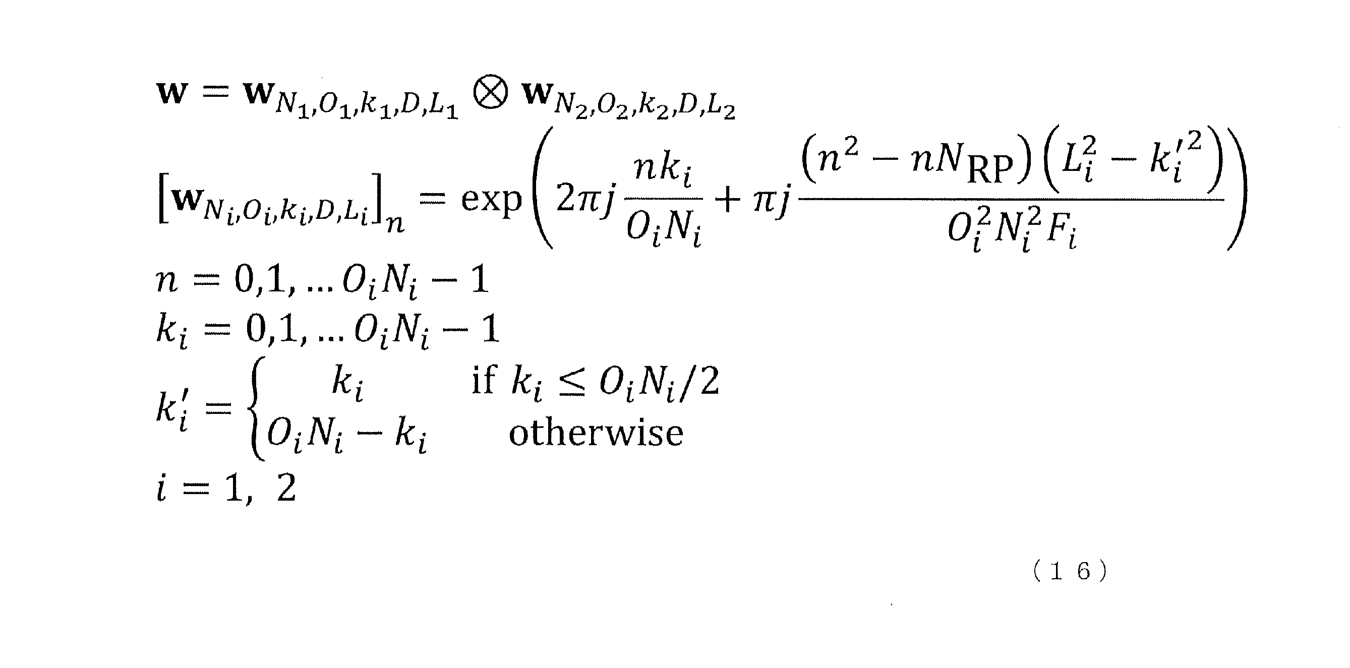
<RIS動作モード>
RISは、反射モード、屈折モード、散乱モード、吸収モード、変調モードなどを含むさまざまなモードで動作するように導入される。そして、干渉除去、ビームシェイピング、特定領域(例えば、IOS(Intelligent Omni-Surfaces)など)でのパフォーマンス向上などのさまざまな目的を達成するには、RISのすべてまたは特定のエレメントの動作モードを制御する必要がある。
RISは、反射モード、屈折モード、散乱モード、吸収モード、変調モードなどを含むさまざまなモードで動作するように導入される。そして、干渉除去、ビームシェイピング、特定領域(例えば、IOS(Intelligent Omni-Surfaces)など)でのパフォーマンス向上などのさまざまな目的を達成するには、RISのすべてまたは特定のエレメントの動作モードを制御する必要がある。
以下、アイドル状態から動作状態に移行するモード、反射モード及び屈折モード、マルチビーム指示、及び、変調について説明する。
<アイドル状態から動作状態へ>
ここで、アイドル状態とは、例えば、散乱モード、及び/又は、吸収モードに対応する。動作状態とは、例えば、反射モード、屈折モード、及び/又は、変調モードに対応する。
ここで、アイドル状態とは、例えば、散乱モード、及び/又は、吸収モードに対応する。動作状態とは、例えば、反射モード、屈折モード、及び/又は、変調モードに対応する。
アイドル状態では、RISからの潜在的な干渉を避けるために、システムによって吸収されるエネルギーが、RIS-MTの電力として使用されてもよい。
アイドル状態での切り替えの指示に関して、以下の4つのオプションのいずれか少なくとも1つが適用されてもよい。
オプション1では、特定の信号が定義される。ネットワークからの特定の信号を検出すると、RISは、アイドル状態から動作状態に切り替わる。あるいは、ネットワークからの特定の信号を検出すると、RISは、動作状態からアイドル状態に切り替わる。
オプション2では、アイドルの指示、または、動作モードの指示が新たに受信されるまで、アイドルの指示、または、動作モードの指示が後続の1以上の時間単位に適用される。
オプション3では、アイドル状態又は動作状態が、時間単位で指示される。
オプション4では、NCRと同様に、有効なビーム又はコードブックが、時間単位に対して指示される場合は動作モードであり、そうでない場合は アイドルモードである。
<反射モードおよび屈折モード>
このモードは、例えば、Intelligent Omni-Surfaces(IOS)であってよい。
このモードは、例えば、Intelligent Omni-Surfaces(IOS)であってよい。
IOSの場合、特定の要件に基づいて、反射カバレッジエリアと屈折カバレッジエリアの両方の電力分布を動的に調整する。
反射と屈折の電力分布が、ネットワークによって指示されてもよい。この指示に関しては、2つのオプションの何れかが適用されてもよい。オプション1では、新しい指示が受信されるまで、電力分布の指示が、後続の時間単位に適用される。オプション2では、電力配分の指示が、時間単位で行われる。
<マルチビームの指示>
例えば、通信と位置推定(例えば、positioning)とが同時に行われることが想定される。
例えば、通信と位置推定(例えば、positioning)とが同時に行われることが想定される。
特定の要件に応じて、ビームの数とビーム間の電力割り当ての両方が、実際のニーズに基づいて動的に調整される。
例えば、通信と位置推定(例えば、positioning)とが同時に行われることが想定されるとしたが、通信と位置推定が同時に行われるケースと、通信と位置推定の一方が行われるケースとが、切り替えられてもよい。また、ビームの数とビーム間の電力割り当ての一方が、実際のニーズに基づいて動的に調整され、他方が調整されないケースが存在してもよい。
<変調モード>
変調モードにおいて、RISは、例えば、入射信号を変調する。
変調モードにおいて、RISは、例えば、入射信号を変調する。
RISは、入射波の信号を変調するために利用されてもよい。RIS内の個々のエレメントの位相シフトを調整することにより、信号が変調されてもよいし、信号のシェイピング、入射波への情報のエンコードなどのさまざまな機能が可能になってよい。
RISが信号を変調するかどうかは、ネットワークによって指示されてもよい。この指示に関して、2つのオプションの少なくとも一方が適用されてもよい。オプション1では、新しい指示が受信されるまで、RISが信号を変調するかどうかの指示は後続の時間単位に適用される。オプション2では、RISが信号を変調するかどうかの指示は時間単位で行われる。
<RISのSSB転送方法>
既存の方法では、RISは、複数のナロービームを使用して、gNBによって送信されたSSBを中継する。ただし、これらの方法には、通常、SSBリソースの大幅な割り当てが含まれるか、あるいは、SSB方法への大幅な変更が必要になる。
既存の方法では、RISは、複数のナロービームを使用して、gNBによって送信されたSSBを中継する。ただし、これらの方法には、通常、SSBリソースの大幅な割り当てが含まれるか、あるいは、SSB方法への大幅な変更が必要になる。
一方で、上述した提案のRISのSSB転送方法では、既存の提案とは対照的に、RISは、ワイドビームを利用して、gNBによって送信されたSSBリソースをUEに転送する。
上述した提案により、SSBリソースの大幅な割り当ての必要性を抑えることができる。
<SSBの電力指示>
ワイドビームを使用してRISによって転送されるSNRのSNRがカバレッジエリア内の1以上のUEの復調しきい値に確実に達するようにするために、基地局からRISに送信されるSSBのビームのパワーを、他のSSBのビームとは異なる方法で調整してもよい。
ワイドビームを使用してRISによって転送されるSNRのSNRがカバレッジエリア内の1以上のUEの復調しきい値に確実に達するようにするために、基地局からRISに送信されるSSBのビームのパワーを、他のSSBのビームとは異なる方法で調整してもよい。
<RISによるSSBの転送の仕様への影響>
既存の仕様内では、SSBの送信電力は、上位レイヤのパラメータ(例えば、ss-PBCH-BlockPower)によって与えられる。さらに、CSI-RSのEPREは、ss-PBCH-BlockPowerと上位レイヤのパラメータによって提供されるSSBのTx電力へのオフセットとに基づいて導出される。このような導出では、異なるSSBの電力が互いに異なる場合、導出方法を拡張しなければならない。
既存の仕様内では、SSBの送信電力は、上位レイヤのパラメータ(例えば、ss-PBCH-BlockPower)によって与えられる。さらに、CSI-RSのEPREは、ss-PBCH-BlockPowerと上位レイヤのパラメータによって提供されるSSBのTx電力へのオフセットとに基づいて導出される。このような導出では、異なるSSBの電力が互いに異なる場合、導出方法を拡張しなければならない。
そこで、SSBのダウンリンクの送信電力は、SSB毎、または、SSBのグループ毎の上位レイヤのパラメータによって与えられる。このパラメータの提供に関して2つのバリエーションの少なくとも1つが適用されてもよい。
バリエーション1:第1のSSBグループ(例えば、UEに直接送信されるSSB)のEPRE(Energy Per Resource Element)は、既存のパラメータを使用して提供される。第1のSSBグループ以外の他のSSBグループ(例えば、RISに送信されるSSB)のEPREは、新しいパラメータによって提供される。なお、ここでの第1のSSBグループは、送信順が最初であるSSBグループであってもよい。
バリエーション2:第1のSSBグループ(例えば、UEに直接送信されるSSB)のEPREは、既存のパラメータを使用して直接提供される。第1のSSBグループ以外の他のSSBグループ(例えば、RISに送信されるSSB)のEPREは、第1のSSBグループのEPREに対するオフセットとして提供される。
既存の仕様内では、CSI-RSのEPREは、上位レイヤのパラメータによって与えられる電力のオフセットと、SSBの下りリンクの送信電力(SSB DL Tx電力)とから導出される。このような導出では、異なるSSBの電力が互いに異なる場合、導出方法を拡張しなければならない。例えば、以下の3つのオプションの何れかが、導出方法として適用されてもよい。
オプション1:CSI-RSの場合、上位レイヤのパラメータによって指示される。CSI-RSのEPREは、何れかのSSBのDL送信電力から導出される。
オプション2:CSI-RSのEPREの場合、デフォルトでは、第1のSSB又は第1のSSBグループのDL送信電力、または、既存のパラメータ(例えば、レガシーパラメータ)によって提供されるSSB送信電力から導出される。
オプション3:CSI-RSの場合、SSBでQCLされるのであれば、CSI-RSのEPREは、QCLリファレンスRSとして使用されるSSBのDL送信電力から導出される。
バリエーション:CSI-RSのEPRE、及び/又は、SSBに対するCSI-RSのパワーオフセットは、CSI-RS毎に提供されてもよいし、CSI-RSグループ毎に提供されてもよい。
<補足事項>
上述したユースケース3のサポートのために、UEは、RTCコードブックをサポートする必要がある。
上述したユースケース3のサポートのために、UEは、RTCコードブックをサポートする必要がある。
各SSBまたはCSI-RSリソースのRTCコードワードはUEに指示される。なお、この場合のコードワードの指示は、関連技術の第1の例及び/又は第2の例のコードワードの指示と同様であってもよい。
なお、各SSBまたはCSI-RSリソースのRTCコードワードの指示に関して、UEには、関連技術の第1の例及び/又は第2の例(例えば、上述した「コードブック/プリコーダに係る各パラメータ」の項目)に示した「N_1」、「N_2」、「O_1」、「O_2」が設定されてもよい。また、UEには、SSBまたはCSI-RSリソースごとにコードワードインデックスである「k_1」、「k_2」が指示されてよい。なお、UEには、関連技術の第1の例及び/又は第2の例と同様に、RISとUEとの間の距離を示す「D_2」が指示されてもよい。あるいは、UEには、SSBまたはCSI-RSリソースごとに、上述した提案における、RISから焦点位置までの焦点距離Fが指示されてもよい。
UEは、UEによって識別されたリファインドビームのRTCコードワードを報告する。この報告には、以下の2つのオプションの何れかが適用されてもよい。
オプション1:報告には、UEによって識別されたリファインドビームのコードワードのインデックスk_1、及び、k_2が含まれる。
オプション2:報告には、UEによって識別されたリファインドビームのコードワードのインデックスk_1、及び、k_1が含まれる。さらに、報告には、SSBまたはCSI-RSのインデックスと、SSBまたはCSI-RSのL1-RSRP/SINRが含まれる。
なお、上述した実施の形態では、RISが、gNBによって送信された信号をUEに転送する下りリンクにおける処理の例を示したが、本開示はこれに限定されない。本開示は、RISが、UEによって送信された信号をgNBに転送する上りリンクにおける処理に適用されてもよいし、RISが、UEによって送信された信号を、当該UEとは別のUEに転送する処理に適用されてもよい。
また、上述した実施の形態では、RISが、gNBとUEとの間に1つ設けられる例を示したが、本開示はこれに限定されない。例えば、gNBとUEとの間に、複数のRISが設けられてもよい。例えば、第1のRISが、gNBによって送信された信号を、第2のRISに転送し、第2のRISが、当該信号を、UEに転送する構成であってもよい。また、この場合、第1のRISが、マルチビーム(例えば、上述したマルチワイドビーム)を生成して、複数の第2のRISに信号を転送し、複数の第2のRISのそれぞれが、更に、信号をUEに転送してもよい。
なお、本開示において、「A/B」及び「A及びBの少なくとも一方」は、互いに読み替えられてもよい。また、本開示において、「A/B/C」は、「A、B及びCの少なくとも1つ」を意味してもよい。
本開示において、通知、アクティベート、ディアクティベート、指示(又は指定(indicate))、選択(select)、設定(configure)、更新(update)、決定(determine)などは、互いに読み替えられてもよい。本開示において、サポートする、制御する、制御できる、動作する、動作できるなどは、互いに読み替えられてもよい。
本開示において、無線リソース制御(Radio Resource Control(RRC))、RRCパラメータ、RRCメッセージ、上位レイヤパラメータ、フィールド、情報要素(Information Element(IE))、設定などは、互いに読み替えられてもよい。本開示において、Medium Access Control制御要素(MAC Control Element(CE))、更新コマンド、アクティベーション/ディアクティベーションコマンドなどは、互いに読み替えられてもよい。
本開示において、上位レイヤシグナリングは、例えば、Radio Resource Control(RRC)シグナリング、Medium Access Control(MAC)シグナリング、ブロードキャスト情報、その他のメッセージ(例えば、測位用プロトコル(例えば、NR Positioning Protocol A(NRPPa)/LTE Positioning Protocol(LPP))メッセージなどの、コアネットワークからのメッセージ)などのいずれか、又はこれらの組み合わせであってもよい。
本開示において、MACシグナリングは、例えば、MAC制御要素(MAC Control Element(MAC CE))、MAC Protocol Data Unit(PDU)などを用いてもよい。ブロードキャスト情報は、例えば、マスタ情報ブロック(Master Information Block(MIB))、システム情報ブロック(System Information Block(SIB))、最低限のシステム情報(Remaining Minimum System Information(RMSI))、その他のシステム情報(Other System Information(OSI))などであってもよい。
本開示において、物理レイヤシグナリングは、例えば、下りリンク制御情報(Downlink Control Information(DCI))、上りリンク制御情報(Uplink Control Information(UCI))などであってもよい。
本開示において、アパチャー、アンテナアレイ、アレイ、サブアレイ(複数のアンテナ素子、アレイの一部)、パネル、RIS、RISアレイ、散乱要素アレイ、等は互いに読み替えられてもよい。本開示において、アンテナ、アンテナ素子、散乱要素、等は互いに読み替えられてもよい。
本開示において、NCR、RIS、RISを含むNCR、ネットワークノード、装置、IAB、IAB-MT(Mobile Termination)、IAB-DU(Distribution Unit)、IAB-CU(Central Unit)、端末、基地局、中継局、中継装置、レピータ、反射板、透過板、RIS-NCR、RISタイプNCR、拡張NCR、等は互いに読み替えられてもよい。
<ブロック構成図>
図21は、本開示の一実施の形態に係る基地局100の構成の一例を示すブロック図である。基地局100は、例えば、送信部101と、受信部102と、制御部103と、を含む。基地局100は、端末200(図22参照)と無線によって通信する。なお、送信部101及び受信部102は、あわせて通信部と称されてもよい。また、制御部は、処理部、プロセッサ等と称されてもよい。
図21は、本開示の一実施の形態に係る基地局100の構成の一例を示すブロック図である。基地局100は、例えば、送信部101と、受信部102と、制御部103と、を含む。基地局100は、端末200(図22参照)と無線によって通信する。なお、送信部101及び受信部102は、あわせて通信部と称されてもよい。また、制御部は、処理部、プロセッサ等と称されてもよい。
送信部101は、DL信号を端末200へ送信する。例えば、送信部101は、制御部103による制御の下に、DL信号を送信する。例えば、DL信号には、端末200の信号送信に関するスケジューリングを示す情報(例えば、ULグラント)、上位レイヤの制御情報等が含まれてよい。
例えば、送信部101は、DL信号として、各種の制御信号(上位レイヤ等の制御信号等)、参照信号、データ信号等を端末200及び/又は無線装置300へ送信する。送信部101は、例えば、DL信号として、上記の実施の形態において説明した各種の信号、チャネル、設定情報、制御情報等を端末200へ送信する。
例えば、送信部101は、制御部103によって生成された、端末200の制御に関する情報を端末200へ送信する。また、例えば、送信部101は、制御部103によって生成された、無線装置300の制御に関する情報を無線装置300へ送信する。また、送信部101は、制御部103によって生成されたデータ信号を端末200へ送信する。
受信部102は、端末200から送信されたUL信号を受信する。例えば、受信部102は、制御部103による制御の下に、UL信号を受信する。また、受信部102は、無線装置300から送信されたUL信号を受信してもよい。
例えば、受信部102は、UL信号として、端末200の端末能力情報(例えば、UE capability)を含む信号、各種の制御信号、参照信号、データ信号等を端末200から受信する。また、受信部102は、無線装置300の能力情報(例えば、capability)を含む信号を受信してもよい。
制御部103は、送信部101における送信処理及び受信部102における受信処理を含む、基地局100の(通信)動作全般を制御する。
例えば、制御部103は、上位レイヤからデータ及び制御情報といった情報を取得し、送信部101へ出力する。また、制御部103は、受信部102から受信したデータ及び制御情報等を上位レイヤへ出力する。
例えば、制御部103は、端末200から受信した信号(例えば、データ及び制御情報等)及び/又は上位レイヤから取得したデータ及び制御情報等に基づいて、DL信号の送受信に用いるリソース及び/又はUL信号の送受信に用いるリソースの割り当てを行う。割り当てたリソースに関する情報は、端末200に送信する制御情報に含まれてよい。
制御部103は、上記の実施の形態において説明した送信及び受信以外の動作を実行する(なお、当該動作は、送信部101及び/又は受信部102によって実行されてもよい)。
また、制御部103は、無線装置300の転送動作に関する制御情報を生成してもよい。制御部103は、無線装置300の通信制御に関する指示(例えば、制御情報)を、送信部101を介して、送信してもよい。
図22は、本開示の一実施の形態に係る端末200の構成の一例を示すブロック図である。端末200は、例えば、受信部201と、送信部202と、制御部203と、を含む。端末200は、例えば、基地局100(図21参照)と無線によって通信する。なお、受信部201及び送信部202は、あわせて通信部と称されてもよい。
受信部201は、基地局100から送信されたDL信号を受信する。例えば、受信部201は、制御部203による制御の下に、DL信号を受信する。
例えば、受信部201は、DL信号として、各種の制御信号、参照信号、データ信号等を基地局100から受信する。受信部201は、例えば、DL信号として、上記の実施の形態において説明した各種の信号、チャネル、設定情報、制御情報等を基地局100から受信する。
例えば、受信部201は、基地局100から信号を受信する。
送信部202は、UL信号を基地局100へ送信する。例えば、送信部202は、制御部203による制御の下に、UL信号を送信する。
例えば、送信部202は、UL信号として、端末200の処理能力に関する情報を含む信号、各種の制御信号、参照信号、データ信号等を基地局100へ送信する。
制御部203は、受信部201における受信処理及び送信部202における送信処理を含む、端末200の(通信)動作全般を制御する。
例えば、制御部203は、上位レイヤからデータ及び制御情報といった情報を取得し、送信部202へ出力する。また、制御部203は、例えば、受信部201から受信したデータ及び制御情報等を上位レイヤへ出力する。
制御部203は、上記の実施の形態において説明した送信及び受信以外の動作を実行する(なお、当該動作は、受信部201及び/又は送信部202によって実行されてもよい)。
なお、端末200が基地局100から受信する信号は、基地局100から直接送信された信号であってもよいし、基地局100から送信され、無線装置300によって転送された信号であってもよい。また、端末200が基地局100へ送信する信号は、基地局100によって直接受信されてもよいし、無線装置300によって転送されて基地局100によって受信されてもよい。この場合、端末200は、無線装置300によって転送された信号か否かを認識しなくてよい。
図23は、本開示の一実施の形態に係る無線装置300の構成の一例を示すブロック図である。無線装置300は、RISの一例に対応する。無線装置300は、例えば、受信部301と、送信部302と、制御部303と、を含む。無線継装置300は、例えば、基地局100(図21参照)及び端末200(図22参照)と無線によって通信する。なお、受信部301及び送信部302は、あわせて通信部と称されてもよい。通信部は、電波を放射する放射面(例えば、RISアレイ)を有し、放射面から信号を送信してもよいし、放射面において信号を受信してもよい。
受信部301は、基地局100から送信されたDL信号を受信する。また、受信部301は、端末200から送信されたUL信号を受信する。例えば、受信部301は、制御部303による制御の下に、DL信号及びUL信号を受信する。なお、受信する信号には、基地局100宛の信号、端末200宛の信号、及び、無線装置300宛の信号が含まれてよい。例えば、受信部301は、基地局100から端末200宛に送信された信号(例えば、端末200に固有の信号)を受信する。なお、転送処理には、基地局100から受信した端末200宛の信号を端末200へ送信する処理と、基地局100宛の信号を端末200から受信する処理との少なくとも一方が含まれてよい。
送信部302は、端末200から受信した、基地局100宛のUL信号を基地局100へ送信する。また、送信部302は、基地局100から受信した、端末200宛のDL信号を端末200へ送信する。例えば、送信部302は、制御部303による制御の下に、UL信号を送信する。例えば、送信部302は、基地局100から受信した端末200宛の信号を端末200に転送する。
制御部303は、受信部301における受信処理及び送信部302における送信処理を含む、無線装置300の(通信)動作全般を制御する。
例えば、制御部303は、送信部302が用いるビームを生成する。制御部303は、取得したターゲットエリア(無線装置300がカバーするエリア)に関する情報を使用して、無線装置300とターゲットエリアとの間の幾何学的な関係(例えば、焦点位置または焦点距離)に基づいて、コードワードを選択(決定)する。そして、制御部303は、決定したコードワードを適用して、ビームを生成する制御を行う。
制御部303は、上記の実施の形態において説明した送信及び受信以外の動作を実行する(なお、当該動作は、受信部301及び/又は送信部302によって実行されてもよい)。
なお、本開示における無線装置300(例えば、RIS)は、通信装置の一例であってよい。また、本開示における無線装置300は、転送装置、リレー装置等の別の呼称で呼ばれてもよい。また、本開示における無線装置300は、端末200(例えば、UE)に置き換えられてもよい。例えば、無線装置300は、転送機能(又は中継機能)を有する端末200と捉えてもよい。
上述した無線装置(例えば、RIS)300は、無線装置300と、無線装置300がカバーするエリアとの間の幾何学的な関係に基づいて、コードワードを決定し、コードワードを適用してエリアをカバーするビームを生成する制御部303と、ビームを用いて、信号を出力する通信部と、を備える。
上述した無線装置(例えば、RIS)300において、制御部303は、通信部(送信部302及び/又は受信部301)の放射面とエリアとの間の幾何学的な関係に基づいて焦点位置を決定し、焦点位置に焦点が合うコードワードを決定する。
上述した無線装置(例えば、RIS)300において、制御部303は、エリアが複数である場合、複数のエリアのそれぞれと放射面との間の幾何学的な関係に基づいて焦点位置を決定し、複数のエリアのそれぞれに対応する焦点位置に焦点が合うエリアコードワードを決定し、複数のエリアのそれぞれに対応するエリアコードワードに対する特定の演算処理によってコードワードを決定する。
上述した無線装置(例えば、RIS)300において、通信部は、平面に配置される複数のアンテナエレメントを有し、制御部303は、無線装置300が動作するモードに応じて、アンテナエレメントの少なくとも1つの設定を切り替える。
上述した無線装置(例えば、RIS)300において、制御部303は、エリアの形状に基づいて、コードワードを決定する。
以上、本開示について説明した。なお、上記の説明における項目の区分けは本開示に本質的ではなく、2以上の項目に記載された事項が必要に応じて組み合わせて使用されてよいし、ある項目に記載された事項が、別の項目に記載された事項に(矛盾しない限り)適用されてよい。
<ハードウェア構成等>
上記実施形態の説明に用いたブロック図は、機能単位のブロックを示している。これらの機能ブロック(構成部)は、ハードウェア及びソフトウェアの少なくとも一方の任意の組み合わせによって実現される。また、各機能ブロックの実現方法は特に限定されない。すなわち、各機能ブロックは、物理的又は論理的に結合した1つの装置を用いて実現されてもよいし、物理的又は論理的に分離した2つ以上の装置を直接的又は間接的に(例えば、有線、無線などを用いて)接続し、これら複数の装置を用いて実現されてもよい。機能ブロックは、上記1つの装置又は上記複数の装置にソフトウェアを組み合わせて実現されてもよい。
上記実施形態の説明に用いたブロック図は、機能単位のブロックを示している。これらの機能ブロック(構成部)は、ハードウェア及びソフトウェアの少なくとも一方の任意の組み合わせによって実現される。また、各機能ブロックの実現方法は特に限定されない。すなわち、各機能ブロックは、物理的又は論理的に結合した1つの装置を用いて実現されてもよいし、物理的又は論理的に分離した2つ以上の装置を直接的又は間接的に(例えば、有線、無線などを用いて)接続し、これら複数の装置を用いて実現されてもよい。機能ブロックは、上記1つの装置又は上記複数の装置にソフトウェアを組み合わせて実現されてもよい。
機能には、判断、決定、判定、計算、算出、処理、導出、調査、探索、確認、受信、送信、出力、アクセス、解決、選択、選定、確立、比較、想定、期待、見做し、報知(broadcasting)、通知(notifying)、通信(communicating)、転送(forwarding)、構成(configuring)、再構成(reconfiguring)、割り当て(allocating、mapping)、割り振り(assigning)などがあるが、これらに限られない。たとえば、送信を機能させる機能ブロック(構成部)は、送信部(transmitting unit)や送信機(transmitter)と呼称される。いずれも、上述したとおり、実現方法は特に限定されない。
例えば、本開示の一実施の形態における基地局、端末、及び無線装置などは、本開示の無線通信方法の処理を行うコンピュータとして機能してもよい。図24は、本開示の一実施の形態に係る基地局、端末、及び無線装置のハードウェア構成の一例を示す図である。上述の基地局100、端末200、及び無線装置300は、物理的には、プロセッサ1001、メモリ1002、ストレージ1003、通信装置1004、入力装置1005、出力装置1006、バス1007などを含むコンピュータ装置として構成されてもよい。
なお、以下の説明では、「装置」という文言は、回路、デバイス、ユニットなどに読み替えることができる。基地局100、端末200、及び無線装置300のハードウェア構成は、図に示した各装置を1つ又は複数含むように構成されてもよいし、一部の装置を含まずに構成されてもよい。
基地局100、端末200、及び無線装置300における各機能は、プロセッサ1001、メモリ1002などのハードウェア上に所定のソフトウェア(プログラム)を読み込ませることによって、プロセッサ1001が演算を行い、通信装置1004による通信を制御したり、メモリ1002及びストレージ1003におけるデータの読み出し及び書き込みの少なくとも一方を制御したりすることによって実現される。
プロセッサ1001は、例えば、オペレーティングシステムを動作させてコンピュータ全体を制御する。プロセッサ1001は、周辺装置とのインターフェース、制御装置、演算装置、レジスタなどを含む中央処理装置(CPU:Central Processing Unit)によって構成されてもよい。例えば、上述の制御部103、制御部203、及び制御部303などは、プロセッサ1001によって実現されてもよい。
また、プロセッサ1001は、プログラム(プログラムコード)、ソフトウェアモジュール、データなどを、ストレージ1003及び通信装置1004の少なくとも一方からメモリ1002に読み出し、これらに従って各種の処理を実行する。プログラムとしては、上述の実施の形態において説明した動作の少なくとも一部をコンピュータに実行させるプログラムが用いられる。例えば、端末200の制御部203は、メモリ1002に格納され、プロセッサ1001において動作する制御プログラムによって実現されてもよく、他の機能ブロックについても同様に実現されてもよい。上述の各種処理は、1つのプロセッサ1001によって実行される旨を説明してきたが、2以上のプロセッサ1001により同時又は逐次に実行されてもよい。プロセッサ1001は、1以上のチップによって実装されてもよい。なお、プログラムは、電気通信回線を介してネットワークから送信されても良い。
メモリ1002は、コンピュータ読み取り可能な記録媒体であり、例えば、ROM(Read Only Memory)、EPROM(Erasable Programmable ROM)、EEPROM(Electrically Erasable Programmable ROM)、RAM(Random Access Memory)などの少なくとも1つによって構成されてもよい。メモリ1002は、レジスタ、キャッシュ、メインメモリ(主記憶装置)などと呼ばれてもよい。メモリ1002は、本開示の一実施の形態に係る無線通信方法を実施するために実行可能なプログラム(プログラムコード)、ソフトウェアモジュールなどを保存することができる。
ストレージ1003は、コンピュータ読み取り可能な記録媒体であり、例えば、CD-ROM(Compact Disc ROM)などの光ディスク、ハードディスクドライブ、フレキシブルディスク、光磁気ディスク(例えば、コンパクトディスク、デジタル多用途ディスク、Blue-ray(登録商標)ディスク)、スマートカード、フラッシュメモリ(例えば、カード、スティック、キードライブ)、フロッピー(登録商標)ディスク、磁気ストリップなどの少なくとも1つによって構成されてもよい。ストレージ1003は、補助記憶装置と呼ばれてもよい。上述の記憶媒体は、例えば、メモリ1002及びストレージ1003の少なくとも一方を含むデータベース、サーバその他の適切な媒体であってもよい。
通信装置1004は、有線ネットワーク及び無線ネットワークの少なくとも一方を介してコンピュータ間の通信を行うためのハードウェア(送受信デバイス)であり、例えばネットワークデバイス、ネットワークコントローラ、ネットワークカード、通信モジュールなどともいう。通信装置1004は、例えば周波数分割複信(FDD:Frequency Division Duplex)及び時分割複信(TDD:Time Division Duplex)の少なくとも一方を実現するために、高周波スイッチ、デュプレクサ、フィルタ、周波数シンセサイザなどを含んで構成されてもよい。例えば、上述の送信部101、受信部102、受信部201、送信部202、受信部301、及び送信部302などは、通信装置1004によって実現されてもよい。
入力装置1005は、外部からの入力を受け付ける入力デバイス(例えば、キーボード、マウス、マイクロフォン、スイッチ、ボタン、センサなど)である。出力装置1006は、外部への出力を実施する出力デバイス(例えば、ディスプレイ、スピーカー、LEDランプなど)である。なお、入力装置1005及び出力装置1006は、一体となった構成(例えば、タッチパネル)であってもよい。
また、プロセッサ1001、メモリ1002などの各装置は、情報を通信するためのバス1007によって接続される。バス1007は、単一のバスを用いて構成されてもよいし、装置間ごとに異なるバスを用いて構成されてもよい。
また、基地局100、端末200、及び無線装置300は、マイクロプロセッサ、デジタル信号プロセッサ(DSP:Digital Signal Processor)、ASIC(Application Specific Integrated Circuit)、PLD(Programmable Logic Device)、FPGA(Field Programmable Gate Array)などのハードウェアを含んで構成されてもよく、当該ハードウェアにより、各機能ブロックの一部又は全てが実現されてもよい。例えば、プロセッサ1001は、これらのハードウェアの少なくとも1つを用いて実装されてもよい。
<情報の通知、シグナリング>
情報の通知は、本開示において説明した実施の形態に限られず、他の方法を用いて行われてもよい。例えば、情報の通知は、物理レイヤシグナリング(例えば、DCI(Downlink Control Information)、UCI(Uplink Control Information))、上位レイヤシグナリング(例えば、RRC(Radio Resource Control)シグナリング、MAC(Medium Access Control)シグナリング、報知情報(MIB(Master Information Block)、SIB(System Information Block)))、その他の信号又はこれらの組み合わせによって実施されてもよい。また、RRCシグナリングは、RRCメッセージと呼ばれてもよく、例えば、RRC接続セットアップ(RRC Connection Setup)メッセージ、RRC接続再構成(RRC Connection Reconfiguration)メッセージなどであってもよい。
情報の通知は、本開示において説明した実施の形態に限られず、他の方法を用いて行われてもよい。例えば、情報の通知は、物理レイヤシグナリング(例えば、DCI(Downlink Control Information)、UCI(Uplink Control Information))、上位レイヤシグナリング(例えば、RRC(Radio Resource Control)シグナリング、MAC(Medium Access Control)シグナリング、報知情報(MIB(Master Information Block)、SIB(System Information Block)))、その他の信号又はこれらの組み合わせによって実施されてもよい。また、RRCシグナリングは、RRCメッセージと呼ばれてもよく、例えば、RRC接続セットアップ(RRC Connection Setup)メッセージ、RRC接続再構成(RRC Connection Reconfiguration)メッセージなどであってもよい。
<適用システム>
本開示において説明した実施の形態は、LTE(Long Term Evolution)、LTE-A(LTE-Advanced)、SUPER 3G、IMT-Advanced、4G(4th generation mobile communication system)、5G(5th generation mobile communication system)、6th generation mobile communication system(6G)、xth generation mobile communication system(xG)(xG(xは、例えば整数、小数))、FRA(Future Radio Access)、NR(new Radio)、New radio access(NX)、Future generation radio access(FX)、W-CDMA(登録商標)、GSM(登録商標)、CDMA2000、UMB(Ultra Mobile Broadband)、IEEE 802.11(Wi-Fi(登録商標))、IEEE 802.16(WiMAX(登録商標))、IEEE 802.20、UWB(Ultra-WideBand)、Bluetooth(登録商標)、その他の適切なシステムを利用するシステム及びこれらに基づいて拡張、修正、作成、規定された次世代システムの少なくとも一つに適用されてもよい。また、複数のシステムが組み合わされて(例えば、LTE及びLTE-Aの少なくとも一方と5Gとの組み合わせ等)適用されてもよい。
本開示において説明した実施の形態は、LTE(Long Term Evolution)、LTE-A(LTE-Advanced)、SUPER 3G、IMT-Advanced、4G(4th generation mobile communication system)、5G(5th generation mobile communication system)、6th generation mobile communication system(6G)、xth generation mobile communication system(xG)(xG(xは、例えば整数、小数))、FRA(Future Radio Access)、NR(new Radio)、New radio access(NX)、Future generation radio access(FX)、W-CDMA(登録商標)、GSM(登録商標)、CDMA2000、UMB(Ultra Mobile Broadband)、IEEE 802.11(Wi-Fi(登録商標))、IEEE 802.16(WiMAX(登録商標))、IEEE 802.20、UWB(Ultra-WideBand)、Bluetooth(登録商標)、その他の適切なシステムを利用するシステム及びこれらに基づいて拡張、修正、作成、規定された次世代システムの少なくとも一つに適用されてもよい。また、複数のシステムが組み合わされて(例えば、LTE及びLTE-Aの少なくとも一方と5Gとの組み合わせ等)適用されてもよい。
<処理手順等>
本開示において説明した各態様/実施形態の処理手順、シーケンス、フローチャートなどは、矛盾の無い限り、順序を入れ替えてもよい。例えば、本開示において説明した方法については、例示的な順序を用いて様々なステップの要素を提示しており、提示した特定の順序に限定されない。
本開示において説明した各態様/実施形態の処理手順、シーケンス、フローチャートなどは、矛盾の無い限り、順序を入れ替えてもよい。例えば、本開示において説明した方法については、例示的な順序を用いて様々なステップの要素を提示しており、提示した特定の順序に限定されない。
<基地局の動作>
本開示において基地局によって行われるとした特定動作は、場合によってはその上位ノード(upper node)によって行われることもある。基地局を有する1つ又は複数のネットワークノード(network nodes)からなるネットワークにおいて、端末との通信のために行われる様々な動作は、基地局及び基地局以外の他のネットワークノード(例えば、MME又はS-GWなどが考えられるが、これらに限られない)の少なくとも1つによって行われ得ることは明らかである。上記において基地局以外の他のネットワークノードが1つである場合を例示したが、複数の他のネットワークノードの組み合わせ(例えば、MME及びS-GW)であってもよい。
本開示において基地局によって行われるとした特定動作は、場合によってはその上位ノード(upper node)によって行われることもある。基地局を有する1つ又は複数のネットワークノード(network nodes)からなるネットワークにおいて、端末との通信のために行われる様々な動作は、基地局及び基地局以外の他のネットワークノード(例えば、MME又はS-GWなどが考えられるが、これらに限られない)の少なくとも1つによって行われ得ることは明らかである。上記において基地局以外の他のネットワークノードが1つである場合を例示したが、複数の他のネットワークノードの組み合わせ(例えば、MME及びS-GW)であってもよい。
<入出力の方向>
情報等(<情報、信号>の項目参照)は、上位レイヤ(又は下位レイヤ)から下位レイヤ(又は上位レイヤ)へ出力され得る。複数のネットワークノードを介して入出力されてもよい。
情報等(<情報、信号>の項目参照)は、上位レイヤ(又は下位レイヤ)から下位レイヤ(又は上位レイヤ)へ出力され得る。複数のネットワークノードを介して入出力されてもよい。
<入出力された情報等の扱い>
入出力された情報等は特定の場所(例えば、メモリ)に保存されてもよいし、管理テーブルを用いて管理してもよい。入出力される情報等は、上書き、更新、又は追記され得る。出力された情報等は削除されてもよい。入力された情報等は他の装置へ送信されてもよい。
入出力された情報等は特定の場所(例えば、メモリ)に保存されてもよいし、管理テーブルを用いて管理してもよい。入出力される情報等は、上書き、更新、又は追記され得る。出力された情報等は削除されてもよい。入力された情報等は他の装置へ送信されてもよい。
<判定方法>
判定は、1ビットで表される値(0か1か)によって行われてもよいし、真偽値(Boolean:true又はfalse)によって行われてもよいし、数値の比較(例えば、所定の値との比較)によって行われてもよい。
判定は、1ビットで表される値(0か1か)によって行われてもよいし、真偽値(Boolean:true又はfalse)によって行われてもよいし、数値の比較(例えば、所定の値との比較)によって行われてもよい。
<態様のバリエーション等>
本開示において説明した各態様/実施形態は単独で用いてもよいし、組み合わせて用いてもよいし、実行に伴って切り替えて用いてもよい。また、所定の情報の通知(例えば、「Xであること」の通知)は、明示的に行うものに限られず、暗黙的(例えば、当該所定の情報の通知を行わない)ことによって行われてもよい。
本開示において説明した各態様/実施形態は単独で用いてもよいし、組み合わせて用いてもよいし、実行に伴って切り替えて用いてもよい。また、所定の情報の通知(例えば、「Xであること」の通知)は、明示的に行うものに限られず、暗黙的(例えば、当該所定の情報の通知を行わない)ことによって行われてもよい。
以上、本開示について詳細に説明したが、当業者にとっては、本開示が本開示中に説明した実施形態に限定されるものではないということは明らかである。本開示は、請求の範囲の記載により定まる本開示の趣旨及び範囲を逸脱することなく修正及び変更態様として実施することができる。したがって、本開示の記載は、例示説明を目的とするものであり、本開示に対して何ら制限的な意味を有するものではない。
<ソフトウェア>
ソフトウェアは、ソフトウェア、ファームウェア、ミドルウェア、マイクロコード、ハードウェア記述言語と呼ばれるか、他の名称で呼ばれるかを問わず、命令、命令セット、コード、コードセグメント、プログラムコード、プログラム、サブプログラム、ソフトウェアモジュール、アプリケーション、ソフトウェアアプリケーション、ソフトウェアパッケージ、ルーチン、サブルーチン、オブジェクト、実行可能ファイル、実行スレッド、手順、機能などを意味するよう広く解釈されるべきである。
ソフトウェアは、ソフトウェア、ファームウェア、ミドルウェア、マイクロコード、ハードウェア記述言語と呼ばれるか、他の名称で呼ばれるかを問わず、命令、命令セット、コード、コードセグメント、プログラムコード、プログラム、サブプログラム、ソフトウェアモジュール、アプリケーション、ソフトウェアアプリケーション、ソフトウェアパッケージ、ルーチン、サブルーチン、オブジェクト、実行可能ファイル、実行スレッド、手順、機能などを意味するよう広く解釈されるべきである。
また、ソフトウェア、命令、情報などは、伝送媒体を介して送受信されてもよい。例えば、ソフトウェアが、有線技術(同軸ケーブル、光ファイバケーブル、ツイストペア、デジタル加入者回線(DSL:Digital Subscriber Line)など)及び無線技術(赤外線、マイクロ波など)の少なくとも一方を使用してウェブサイト、サーバ、又は他のリモートソースから送信される場合、これらの有線技術及び無線技術の少なくとも一方は、伝送媒体の定義内に含まれる。
<情報、信号>
本開示において説明した情報、信号などは、様々な異なる技術のいずれかを使用して表されてもよい。例えば、上記の説明全体に渡って言及され得るデータ、命令、コマンド、情報、信号、ビット、シンボル、チップなどは、電圧、電流、電磁波、磁界若しくは磁性粒子、光場若しくは光子、又はこれらの任意の組み合わせによって表されてもよい。
本開示において説明した情報、信号などは、様々な異なる技術のいずれかを使用して表されてもよい。例えば、上記の説明全体に渡って言及され得るデータ、命令、コマンド、情報、信号、ビット、シンボル、チップなどは、電圧、電流、電磁波、磁界若しくは磁性粒子、光場若しくは光子、又はこれらの任意の組み合わせによって表されてもよい。
なお、本開示において説明した用語及び本開示の理解に必要な用語については、同一の又は類似する意味を有する用語と置き換えてもよい。例えば、チャネル及びシンボルの少なくとも一方は信号(シグナリング)であってもよい。また、信号はメッセージであってもよい。また、コンポーネントキャリア(CC:Component Carrier)は、キャリア周波数、セル、周波数キャリアなどと呼ばれてもよい。
<システム、ネットワーク>
本開示において使用する「システム」及び「ネットワーク」という用語は、互換的に使用される。
本開示において使用する「システム」及び「ネットワーク」という用語は、互換的に使用される。
<パラメータ、チャネルの名称>
また、本開示において説明した情報、パラメータなどは、絶対値を用いて表されてもよいし、所定の値からの相対値を用いて表されてもよいし、対応する別の情報を用いて表されてもよい。例えば、無線リソースはインデックスによって指示されるものであってもよい。
また、本開示において説明した情報、パラメータなどは、絶対値を用いて表されてもよいし、所定の値からの相対値を用いて表されてもよいし、対応する別の情報を用いて表されてもよい。例えば、無線リソースはインデックスによって指示されるものであってもよい。
上述したパラメータに使用する名称はいかなる点においても限定的な名称ではない。さらに、これらのパラメータを使用する数式等は、本開示で明示的に開示したものと異なる場合もある。様々なチャネル(例えば、PUCCH、PDCCHなど)及び情報要素は、あらゆる好適な名称によって識別できるので、これらの様々なチャネル及び情報要素に割り当てている様々な名称は、いかなる点においても限定的な名称ではない。
<基地局>
本開示においては、「基地局(BS:Base Station)」、「無線基地局」、「固定局(fixed station)」、「NodeB」、「eNodeB(eNB)」、「gNodeB(gNB)」、「アクセスポイント(access point)」、「送信ポイント(transmission point)」、「受信ポイント(reception point)、「送受信ポイント(transmission/reception point)」、「セル」、「セクタ」、「セルグループ」、「キャリア」、「コンポーネントキャリア」などの用語は、互換的に使用され得る。基地局は、マクロセル、スモールセル、フェムトセル、ピコセルなどの用語で呼ばれる場合もある。
本開示においては、「基地局(BS:Base Station)」、「無線基地局」、「固定局(fixed station)」、「NodeB」、「eNodeB(eNB)」、「gNodeB(gNB)」、「アクセスポイント(access point)」、「送信ポイント(transmission point)」、「受信ポイント(reception point)、「送受信ポイント(transmission/reception point)」、「セル」、「セクタ」、「セルグループ」、「キャリア」、「コンポーネントキャリア」などの用語は、互換的に使用され得る。基地局は、マクロセル、スモールセル、フェムトセル、ピコセルなどの用語で呼ばれる場合もある。
基地局は、1つ又は複数(例えば、3つ)のセルを収容することができる。基地局が複数のセルを収容する場合、基地局のカバレッジエリア全体は複数のより小さいエリアに区分でき、各々のより小さいエリアは、基地局サブシステム(例えば、屋内用の小型基地局(RRH:Remote Radio Head)によって通信サービスを提供することもできる。「セル」又は「セクタ」という用語は、このカバレッジにおいて通信サービスを行う基地局及び基地局サブシステムの少なくとも一方のカバレッジエリアの一部又は全体を指す。
<移動局>
本開示においては、「移動局(MS:Mobile Station)」、「ユーザ端末(user terminal)」、「ユーザ装置(UE:User Equipment)」、「端末」などの用語は、互換的に使用され得る。
本開示においては、「移動局(MS:Mobile Station)」、「ユーザ端末(user terminal)」、「ユーザ装置(UE:User Equipment)」、「端末」などの用語は、互換的に使用され得る。
移動局は、当業者によって、加入者局、モバイルユニット、加入者ユニット、ワイヤレスユニット、リモートユニット、モバイルデバイス、ワイヤレスデバイス、ワイヤレス通信デバイス、リモートデバイス、モバイル加入者局、アクセス端末、モバイル端末、ワイヤレス端末、リモート端末、ハンドセット、ユーザエージェント、モバイルクライアント、クライアント、又はいくつかの他の適切な用語で呼ばれる場合もある。
<基地局/移動局>
基地局及び移動局の少なくとも一方は、送信装置、受信装置、通信装置などと呼ばれてもよい。なお、基地局及び移動局の少なくとも一方は、移動体に搭載されたデバイス、移動体自体などであってもよい。当該移動体は、移動可能な物体をいい、移動速度は任意である。また移動体が停止している場合も当然含む。当該移動体は、例えば、車両、輸送車両、自動車、自動二輪車、自転車、コネクテッドカー、ショベルカー、ブルドーザー、ホイールローダー、ダンプトラック、フォークリフト、列車、バス、リヤカー、人力車、船舶(ship and other watercraft)、飛行機、ロケット、人工衛星、ドローン(登録商標)、マルチコプター、クアッドコプター、気球、およびこれらに搭載される物を含み、またこれらに限らない。また、当該移動体は、運行指令に基づいて自律走行する移動体であってもよい。乗り物(例えば、車、飛行機など)であってもよいし、無人で動く移動体(例えば、ドローン、自動運転車など)であってもよいし、ロボット(有人型又は無人型)であってもよい。なお、基地局及び移動局の少なくとも一方は、必ずしも通信動作時に移動しない装置も含む。例えば、基地局及び移動局の少なくとも一方は、センサなどのIoT(Internet of Things)機器であってもよい。
基地局及び移動局の少なくとも一方は、送信装置、受信装置、通信装置などと呼ばれてもよい。なお、基地局及び移動局の少なくとも一方は、移動体に搭載されたデバイス、移動体自体などであってもよい。当該移動体は、移動可能な物体をいい、移動速度は任意である。また移動体が停止している場合も当然含む。当該移動体は、例えば、車両、輸送車両、自動車、自動二輪車、自転車、コネクテッドカー、ショベルカー、ブルドーザー、ホイールローダー、ダンプトラック、フォークリフト、列車、バス、リヤカー、人力車、船舶(ship and other watercraft)、飛行機、ロケット、人工衛星、ドローン(登録商標)、マルチコプター、クアッドコプター、気球、およびこれらに搭載される物を含み、またこれらに限らない。また、当該移動体は、運行指令に基づいて自律走行する移動体であってもよい。乗り物(例えば、車、飛行機など)であってもよいし、無人で動く移動体(例えば、ドローン、自動運転車など)であってもよいし、ロボット(有人型又は無人型)であってもよい。なお、基地局及び移動局の少なくとも一方は、必ずしも通信動作時に移動しない装置も含む。例えば、基地局及び移動局の少なくとも一方は、センサなどのIoT(Internet of Things)機器であってもよい。
また、本開示における基地局は、端末で読み替えてもよい。例えば、基地局及び端末間の通信を、複数の端末間の通信(例えば、D2D(Device-to-Device)、V2X(Vehicle-to-Everything)などと呼ばれてもよい)に置き換えた構成について、本開示の実施の形態を適用してもよい。この場合、上述の基地局100が有する機能を端末200及び無線装置300が有する構成としてもよい。また、「上り」及び「下り」などの文言は、端末間通信に対応する文言(例えば、「サイド(side)」)で読み替えられてもよい。例えば、上りチャネル、下りチャネルなどは、サイドチャネルで読み替えられてもよい。
同様に、本開示における端末は、基地局で読み替えてもよい。この場合、上述の端末20が有する機能を基地局100及び中継局300が有する構成としてもよい。
図25に車両2001の構成例を示す。図25に示すように、車両2001は駆動部2002、操舵部2003、アクセルペダル2004、ブレーキペダル2005、シフトレバー2006、前輪2007、後輪2008、車軸2009、電子制御部2010、各種センサ2021~2029、情報サービス部2012と通信モジュール2013を備える。本開示において説明した各態様/実施形態は、車両2001に搭載される通信装置に適用されてもよく、例えば、通信モジュール2013に適用されてもよい。
駆動部2002は例えば、エンジン、モータ、エンジンとモータのハイブリッドで構成される。操舵部2003は、少なくともステアリングホイール(ハンドルとも呼ぶ)を含み、ユーザによって操作されるステアリングホイールの操作に基づいて前輪及び後輪の少なくとも一方を操舵するように構成される。
電子制御部2010は、マイクロプロセッサ2031、メモリ(ROM、RAM)2032、通信ポート(IOポート)2033で構成される。電子制御部2010には、車両2001に備えられた各種センサ2021~2029からの信号が入力される。電子制御部2010は、ECU(Electronic Control Unit)と呼んでも良い。
各種センサ2021~2029からの信号としては、モータの電流をセンシングする電流センサ2021からの電流信号、回転数センサ2022によって取得された前輪や後輪の回転数信号、空気圧センサ2023によって取得された前輪や後輪の空気圧信号、車速センサ2024によって取得された車速信号、加速度センサ2025によって取得された加速度信号、アクセルペダルセンサ2029によって取得されたアクセルペダルの踏み込み量信号、ブレーキペダルセンサ2026によって取得されたブレーキペダルの踏み込み量信号、シフトレバーセンサ2027によって取得されたシフトレバーの操作信号、物体検知センサ2028によって取得された障害物、車両、歩行者等を検出するための検出信号等がある。
情報サービス部2012は、カーナビゲーションシステム、オーディオシステム、スピーカー、テレビ、ラジオといった、運転情報、交通情報、エンターテイメント情報等の各種情報を提供(出力)するための各種機器と、これらの機器を制御する1つ以上のECUとから構成される。情報サービス部2012は、外部装置から通信モジュール2013等を介して取得した情報を利用して、車両2001の乗員に各種マルチメディア情報及びマルチメディアサービスを提供する。
情報サービス部2012は、外部からの入力を受け付ける入力デバイス(例えば、キーボード、マウス、マイクロフォン、スイッチ、ボタン、センサ、タッチパネルなど)を含んでもよいし、外部への出力を実施する出力デバイス(例えば、ディスプレイ、スピーカー、LEDランプ、タッチパネルなど)を含んでもよい。
運転支援システム部2030は、ミリ波レーダ、LiDAR(Light Detection and Ranging)、カメラ、測位ロケータ(例えば、GNSS等)、地図情報(例えば、高精細(HD)マップ、自動運転車(AV)マップ等)、ジャイロシステム(例えば、IMU(Inertial Measurement Unit)、INS(Inertial Navigation System)等)、AI(Artificial Intelligence)チップ、AIプロセッサといった、事故を未然に防止したりドライバの運転負荷を軽減したりするための機能を提供するための各種機器と、これらの機器を制御する1つ以上のECUとから構成される。また、運転支援システム部2030は、通信モジュール2013を介して各種情報を送受信し、運転支援機能又は自動運転機能を実現する。
通信モジュール2013は通信ポートを介して、マイクロプロセッサ2031および車両2001の構成要素と通信することができる。例えば、通信モジュール2013は通信ポート2033を介して、車両2001に備えられた駆動部2002、操舵部2003、アクセルペダル2004、ブレーキペダル2005、シフトレバー2006、前輪2007、後輪2008、車軸2009、電子制御部2010内のマイクロプロセッサ2031及びメモリ(ROM、RAM)2032、センサ2021~29との間でデータを送受信する。
通信モジュール2013は、電子制御部2010のマイクロプロセッサ2031によって制御可能であり、外部装置と通信を行うことが可能な通信デバイスである。例えば、外部装置との間で無線通信を介して各種情報の送受信を行う。通信モジュール2013は、電子制御部2010の内部と外部のどちらにあってもよい。外部装置は、例えば、基地局、移動局等であってもよい。
通信モジュール2013は、電子制御部2010に入力された上述の各種センサ2021~2029からの信号、当該信号に基づいて得られる情報、及び情報サービス部2012を介して得られる外部(ユーザ)からの入力に基づく情報、の少なくとも1つを、無線通信を介して外部装置へ送信してもよい。電子制御部2010、各種センサ2021~2029、情報サービス部2012などは、入力を受け付ける入力部と呼ばれてもよい。例えば、通信モジュール2013によって送信されるPUSCHは、上記入力に基づく情報を含んでもよい。
通信モジュール2013は、外部装置から送信されてきた種々の情報(交通情報、信号情報、車間情報等)を受信し、車両2001に備えられた情報サービス部2012へ表示する。情報サービス部2012は、情報を出力する(例えば、通信モジュール2013によって受信されるPDSCH(又は当該PDSCHから復号されるデータ/情報)に基づいてディスプレイ、スピーカーなどの機器に情報を出力する)出力部と呼ばれてもよい。
また、通信モジュール2013は、外部装置から受信した種々の情報をマイクロプロセッサ2031によって利用可能なメモリ2032へ記憶する。メモリ2032に記憶された情報に基づいて、マイクロプロセッサ2031が車両2001に備えられた駆動部2002、操舵部2003、アクセルペダル2004、ブレーキペダル2005、シフトレバー2006、前輪2007、後輪2008、車軸2009、センサ2021~2029等の制御を行ってもよい。
<用語の意味、解釈>
本開示で使用する「判断(determining)」、「決定(determining)」という用語は、多種多様な動作を包含する場合がある。「判断」、「決定」は、例えば、判定(judging)、計算(calculating)、算出(computing)、処理(processing)、導出(deriving)、調査(investigating)、探索(looking up、search、inquiry)(例えば、テーブル、データベース又は別のデータ構造での探索)、確認(ascertaining)した事を「判断」「決定」したとみなす事などを含み得る。また、「判断」、「決定」は、受信(receiving)(例えば、情報を受信すること)、送信(transmitting)(例えば、情報を送信すること)、入力(input)、出力(output)、アクセス(accessing)(例えば、メモリ中のデータにアクセスすること)した事を「判断」「決定」したとみなす事などを含み得る。また、「判断」、「決定」は、解決(resolving)、選択(selecting)、選定(choosing)、確立(establishing)、比較(comparing)などした事を「判断」「決定」したとみなす事を含み得る。つまり、「判断」「決定」は、何らかの動作を「判断」「決定」したとみなす事を含み得る。また、「判断(決定)」は、「想定する(assuming)」、「期待する(expecting)」、「みなす(considering)」などで読み替えられてもよい。
本開示で使用する「判断(determining)」、「決定(determining)」という用語は、多種多様な動作を包含する場合がある。「判断」、「決定」は、例えば、判定(judging)、計算(calculating)、算出(computing)、処理(processing)、導出(deriving)、調査(investigating)、探索(looking up、search、inquiry)(例えば、テーブル、データベース又は別のデータ構造での探索)、確認(ascertaining)した事を「判断」「決定」したとみなす事などを含み得る。また、「判断」、「決定」は、受信(receiving)(例えば、情報を受信すること)、送信(transmitting)(例えば、情報を送信すること)、入力(input)、出力(output)、アクセス(accessing)(例えば、メモリ中のデータにアクセスすること)した事を「判断」「決定」したとみなす事などを含み得る。また、「判断」、「決定」は、解決(resolving)、選択(selecting)、選定(choosing)、確立(establishing)、比較(comparing)などした事を「判断」「決定」したとみなす事を含み得る。つまり、「判断」「決定」は、何らかの動作を「判断」「決定」したとみなす事を含み得る。また、「判断(決定)」は、「想定する(assuming)」、「期待する(expecting)」、「みなす(considering)」などで読み替えられてもよい。
「接続された(connected)」、「結合された(coupled)」という用語、又はこれらのあらゆる変形は、2又はそれ以上の要素間の直接的又は間接的なあらゆる接続又は結合を意味し、互いに「接続」又は「結合」された2つの要素間に1又はそれ以上の中間要素が存在することを含むことができる。要素間の結合又は接続は、物理的なものであっても、論理的なものであっても、或いはこれらの組み合わせであってもよい。例えば、「接続」は「アクセス」で読み替えられてもよい。本開示で使用する場合、2つの要素は、1又はそれ以上の電線、ケーブル及びプリント電気接続の少なくとも一つを用いて、並びにいくつかの非限定的かつ非包括的な例として、無線周波数領域、マイクロ波領域及び光(可視及び不可視の両方)領域の波長を有する電磁エネルギーなどを用いて、互いに「接続」又は「結合」されると考えることができる。
<参照信号>
参照信号は、RS(Reference Signal)と略称することもでき、適用される標準によってパイロット(Pilot)と呼ばれてもよい。
参照信号は、RS(Reference Signal)と略称することもでき、適用される標準によってパイロット(Pilot)と呼ばれてもよい。
<「に基づいて」の意味>
本開示において使用する「に基づいて」という記載は、別段に明記されていない限り、「のみに基づいて」を意味しない。言い換えれば、「に基づいて」という記載は、「のみに基づいて」と「に少なくとも基づいて」の両方を意味する。
本開示において使用する「に基づいて」という記載は、別段に明記されていない限り、「のみに基づいて」を意味しない。言い換えれば、「に基づいて」という記載は、「のみに基づいて」と「に少なくとも基づいて」の両方を意味する。
<「第1の」、「第2の」>
本開示において使用する「第1の」、「第2の」などの呼称を使用した要素へのいかなる参照も、それらの要素の量又は順序を全般的に限定しない。これらの呼称は、2つ以上の要素間を区別する便利な方法として本開示において使用され得る。したがって、第1及び第2の要素への参照は、2つの要素のみが採用され得ること、又は何らかの形で第1の要素が第2の要素に先行しなければならないことを意味しない。
本開示において使用する「第1の」、「第2の」などの呼称を使用した要素へのいかなる参照も、それらの要素の量又は順序を全般的に限定しない。これらの呼称は、2つ以上の要素間を区別する便利な方法として本開示において使用され得る。したがって、第1及び第2の要素への参照は、2つの要素のみが採用され得ること、又は何らかの形で第1の要素が第2の要素に先行しなければならないことを意味しない。
<手段>
上記の各装置の構成における「手段」を、「部」、「回路」、「デバイス」等に置き換えてもよい。
上記の各装置の構成における「手段」を、「部」、「回路」、「デバイス」等に置き換えてもよい。
<オープン形式>
本開示において、「含む(include)」、「含んでいる(including)」及びそれらの変形が使用されている場合、これらの用語は、用語「備える(comprising)」と同様に、包括的であることが意図される。さらに、本開示において使用されている用語「又は(or)」は、排他的論理和ではないことが意図される。
本開示において、「含む(include)」、「含んでいる(including)」及びそれらの変形が使用されている場合、これらの用語は、用語「備える(comprising)」と同様に、包括的であることが意図される。さらに、本開示において使用されている用語「又は(or)」は、排他的論理和ではないことが意図される。
<TTI等の時間単位、RBなどの周波数単位、無線フレーム構成>
無線フレームは時間領域において1つ又は複数のフレームによって構成されてもよい。時間領域において1つ又は複数の各フレームはサブフレームと呼ばれてもよい。サブフレームは更に時間領域において1つ又は複数のスロットによって構成されてもよい。サブフレームは、ニューメロロジー(numerology)に依存しない固定の時間長(例えば、1ms)であってもよい。
無線フレームは時間領域において1つ又は複数のフレームによって構成されてもよい。時間領域において1つ又は複数の各フレームはサブフレームと呼ばれてもよい。サブフレームは更に時間領域において1つ又は複数のスロットによって構成されてもよい。サブフレームは、ニューメロロジー(numerology)に依存しない固定の時間長(例えば、1ms)であってもよい。
ニューメロロジーは、ある信号又はチャネルの送信及び受信の少なくとも一方に適用される通信パラメータであってもよい。ニューメロロジーは、例えば、サブキャリア間隔(SCS:SubCarrier Spacing)、帯域幅、シンボル長、サイクリックプレフィックス長、送信時間間隔(TTI:Transmission Time Interval)、TTIあたりのシンボル数、無線フレーム構成、送受信機が周波数領域において行う特定のフィルタリング処理、送受信機が時間領域において行う特定のウィンドウイング処理などの少なくとも1つを示してもよい。
スロットは、時間領域において1つ又は複数のシンボル(OFDM(Orthogonal Frequency Division Multiplexing)シンボル、SC-FDMA(Single Carrier Frequency Division Multiple Access)シンボル等)で構成されてもよい。スロットは、ニューメロロジーに基づく時間単位であってもよい。
スロットは、複数のミニスロットを含んでもよい。各ミニスロットは、時間領域において1つ又は複数のシンボルによって構成されてもよい。また、ミニスロットは、サブスロットと呼ばれてもよい。ミニスロットは、スロットよりも少ない数のシンボルによって構成されてもよい。ミニスロットより大きい時間単位で送信されるPDSCH(又はPUSCH)は、PDSCH(又はPUSCH)マッピングタイプAと呼ばれてもよい。ミニスロットを用いて送信されるPDSCH(又はPUSCH)は、PDSCH(又はPUSCH)マッピングタイプBと呼ばれてもよい。
無線フレーム、サブフレーム、スロット、ミニスロット及びシンボルは、いずれも信号を伝送する際の時間単位を表す。無線フレーム、サブフレーム、スロット、ミニスロット及びシンボルは、それぞれに対応する別の呼称が用いられてもよい。
例えば、1サブフレームは送信時間間隔(TTI:Transmission Time Interval)と呼ばれてもよいし、複数の連続したサブフレームがTTIと呼ばれてよいし、1スロット又は1ミニスロットがTTIと呼ばれてもよい。つまり、サブフレーム及びTTIの少なくとも一方は、既存のLTEにおけるサブフレーム(1ms)であってもよいし、1msより短い期間(例えば、1-13シンボル)であってもよいし、1msより長い期間であってもよい。なお、TTIを表す単位は、サブフレームではなくスロット、ミニスロットなどと呼ばれてもよい。
ここで、TTIは、例えば、無線通信におけるスケジューリングの最小時間単位のことをいう。例えば、LTEシステムでは、基地局が各ユーザ端末に対して、無線リソース(各ユーザ端末において使用することが可能な周波数帯域幅、送信電力など)を、TTI単位で割り当てるスケジューリングを行う。なお、TTIの定義はこれに限られない。
TTIは、チャネル符号化されたデータパケット(トランスポートブロック)、コードブロック、コードワードなどの送信時間単位であってもよいし、スケジューリング、リンクアダプテーションなどの処理単位となってもよい。なお、TTIが与えられたとき、実際にトランスポートブロック、コードブロック、コードワードなどがマッピングされる時間区間(例えば、シンボル数)は、当該TTIよりも短くてもよい。
なお、1スロット又は1ミニスロットがTTIと呼ばれる場合、1以上のTTI(すなわち、1以上のスロット又は1以上のミニスロット)が、スケジューリングの最小時間単位となってもよい。また、当該スケジューリングの最小時間単位を構成するスロット数(ミニスロット数)は制御されてもよい。
1msの時間長を有するTTIは、通常TTI(LTE Rel.8-12におけるTTI)、ノーマルTTI、ロングTTI、通常サブフレーム、ノーマルサブフレーム、ロングサブフレーム、スロットなどと呼ばれてもよい。通常TTIより短いTTIは、短縮TTI、ショートTTI、部分TTI(partial又はfractional TTI)、短縮サブフレーム、ショートサブフレーム、ミニスロット、サブスロット、スロットなどと呼ばれてもよい。
なお、ロングTTI(例えば、通常TTI、サブフレームなど)は、1msを超える時間長を有するTTIで読み替えてもよいし、ショートTTI(例えば、短縮TTIなど)は、ロングTTIのTTI長未満かつ1ms以上のTTI長を有するTTIで読み替えてもよい。
リソースブロック(RB)は、時間領域及び周波数領域のリソース割当単位であり、周波数領域において、1つ又は複数個の連続した副搬送波(subcarrier)を含んでもよい。RBに含まれるサブキャリアの数は、ニューメロロジーに関わらず同じであってもよく、例えば12であってもよい。RBに含まれるサブキャリアの数は、ニューメロロジーに基づいて決定されてもよい。
また、RBの時間領域は、1つ又は複数個のシンボルを含んでもよく、1スロット、1ミニスロット、1サブフレーム、又は1TTIの長さであってもよい。1TTI、1サブフレームなどは、それぞれ1つ又は複数のリソースブロックで構成されてもよい。
なお、1つ又は複数のRBは、物理リソースブロック(PRB:Physical RB)、サブキャリアグループ(SCG:Sub-Carrier Group)、リソースエレメントグループ(REG:Resource Element Group)、PRBペア、RBペアなどと呼ばれてもよい。
また、リソースブロックは、1つ又は複数のリソースエレメント(RE:Resource Element)によって構成されてもよい。例えば、1REは、1サブキャリア及び1シンボルの無線リソース領域であってもよい。
帯域幅部分(BWP:Bandwidth Part)(部分帯域幅などと呼ばれてもよい)は、あるキャリアにおいて、あるニューメロロジー用の連続する共通RB(common resource blocks)のサブセットのことを表してもよい。ここで、共通RBは、当該キャリアの共通参照ポイントを基準としたRBのインデックスによって特定されてもよい。PRBは、あるBWPで定義され、当該BWP内で番号付けされてもよい。
BWPには、UL用のBWP(UL BWP)と、DL用のBWP(DL BWP)とが含まれてもよい。UEに対して、1キャリア内に1つ又は複数のBWPが設定されてもよい。
設定されたBWPの少なくとも1つがアクティブであってもよく、UEは、アクティブなBWPの外で所定の信号/チャネルを送受信することを想定しなくてもよい。なお、本開示における「セル」、「キャリア」などは、「BWP」で読み替えられてもよい。
上述した無線フレーム、サブフレーム、スロット、ミニスロット及びシンボルなどの構造は例示に過ぎない。例えば、無線フレームに含まれるサブフレームの数、サブフレーム又は無線フレームあたりのスロットの数、スロット内に含まれるミニスロットの数、スロット又はミニスロットに含まれるシンボル及びRBの数、RBに含まれるサブキャリアの数、並びにTTI内のシンボル数、シンボル長、サイクリックプレフィックス(CP:Cyclic Prefix)長などの構成は、様々に変更することができる。
<最大送信電力>
本開示に記載の「最大送信電力」は、送信電力の最大値を意味してもよいし、公称最大送信電力(the nominal UE maximum transmit power)を意味してもよいし、定格最大送信電力(the rated UE maximum transmit power)を意味してもよい。
本開示に記載の「最大送信電力」は、送信電力の最大値を意味してもよいし、公称最大送信電力(the nominal UE maximum transmit power)を意味してもよいし、定格最大送信電力(the rated UE maximum transmit power)を意味してもよい。
<冠詞>
本開示において、例えば、英語でのa、an及びtheのように、翻訳により冠詞が追加された場合、本開示は、これらの冠詞の後に続く名詞が複数形であることを含んでもよい。
本開示において、例えば、英語でのa、an及びtheのように、翻訳により冠詞が追加された場合、本開示は、これらの冠詞の後に続く名詞が複数形であることを含んでもよい。
<「異なる」>
本開示において、「AとBが異なる」という用語は、「AとBが互いに異なる」ことを意味してもよい。なお、当該用語は、「AとBがそれぞれCと異なる」ことを意味してもよい。「離れる」、「結合される」などの用語も、「異なる」と同様に解釈されてもよい。
本開示において、「AとBが異なる」という用語は、「AとBが互いに異なる」ことを意味してもよい。なお、当該用語は、「AとBがそれぞれCと異なる」ことを意味してもよい。「離れる」、「結合される」などの用語も、「異なる」と同様に解釈されてもよい。
本開示の一態様は、無線通信システムに有用である。
10 無線通信システム
20 NG-RAN
100 基地局(gNB)
200 端末(UE)
300 無線装置(RIS)
101,202,302 送信部
102,201,301 受信部
103,203,303 制御部
1001 プロセッサ
1002 メモリ
1003 ストレージ
1004 通信装置
1005 入力装置
1006 出力装置
1007 バス
20 NG-RAN
100 基地局(gNB)
200 端末(UE)
300 無線装置(RIS)
101,202,302 送信部
102,201,301 受信部
103,203,303 制御部
1001 プロセッサ
1002 メモリ
1003 ストレージ
1004 通信装置
1005 入力装置
1006 出力装置
1007 バス
Claims (6)
- 無線装置であって、
前記無線装置と、前記無線装置がカバーするエリアとの間の幾何学的な関係に基づいて、コードワードを決定し、前記コードワードを適用して前記エリアをカバーするビームを生成する制御部と、
前記ビームを用いて、信号を出力する通信部と、
を備える無線装置。 - 前記制御部は、
前記通信部の放射面と前記エリアとの間の前記幾何学的な関係に基づいて焦点位置を決定し、
前記焦点位置に焦点が合う前記コードワードを決定する、
請求項1に記載の無線装置。 - 前記制御部は、前記エリアが複数である場合、前記複数のエリアのそれぞれと前記通信部の放射面との間の前記幾何学的な関係に基づいて焦点位置を決定し、
前記複数のエリアのそれぞれに対応する前記焦点位置に焦点が合うエリアコードワードを決定し、
前記複数のエリアのそれぞれに対応する前記エリアコードワードに対する特定の演算処理によって前記コードワードを決定する、
請求項1に記載の無線装置。 - 前記通信部は、平面に配置される複数のアンテナエレメントを有し、
前記制御部は、前記無線装置が動作するモードに応じて、前記アンテナエレメントの少なくとも1つの設定を切り替える、
請求項1に記載の無線装置。 - 前記制御部は、前記エリアの形状に基づいて、前記コードワードを決定する、
請求項1に記載の無線装置。 - 無線装置が、
前記無線装置と、前記無線装置がカバーするエリアとの間の幾何学的な関係に基づいて、コードワードを決定し、
前記コードワードを適用して前記エリアをカバーするビームを生成し、
前記ビームを用いて、信号を出力する、
制御方法。
Priority Applications (2)
| Application Number | Priority Date | Filing Date | Title |
|---|---|---|---|
| CN202380098883.1A CN121263969A (zh) | 2023-08-18 | 2023-08-18 | 无线装置以及控制方法 |
| PCT/JP2023/029897 WO2025041209A1 (ja) | 2023-08-18 | 2023-08-18 | 無線装置及び制御方法 |
Applications Claiming Priority (1)
| Application Number | Priority Date | Filing Date | Title |
|---|---|---|---|
| PCT/JP2023/029897 WO2025041209A1 (ja) | 2023-08-18 | 2023-08-18 | 無線装置及び制御方法 |
Publications (1)
| Publication Number | Publication Date |
|---|---|
| WO2025041209A1 true WO2025041209A1 (ja) | 2025-02-27 |
Family
ID=94731796
Family Applications (1)
| Application Number | Title | Priority Date | Filing Date |
|---|---|---|---|
| PCT/JP2023/029897 Pending WO2025041209A1 (ja) | 2023-08-18 | 2023-08-18 | 無線装置及び制御方法 |
Country Status (2)
| Country | Link |
|---|---|
| CN (1) | CN121263969A (ja) |
| WO (1) | WO2025041209A1 (ja) |
Cited By (1)
| Publication number | Priority date | Publication date | Assignee | Title |
|---|---|---|---|---|
| US20250105883A1 (en) * | 2023-09-26 | 2025-03-27 | Tsinghua University | Communication wide-area coverage system and method based on reconfigurable intelligent surface technology |
Citations (3)
| Publication number | Priority date | Publication date | Assignee | Title |
|---|---|---|---|---|
| JP2010534020A (ja) * | 2007-07-16 | 2010-10-28 | ノーテル・ネットワークス・リミテッド | 無線ネットワークでの空間分割多重アクセスの提供 |
| US20190173537A1 (en) * | 2017-12-04 | 2019-06-06 | University Of Notre Dame Du Lac | Mitigating beam squint in millimeter wave wireless communication systems |
| WO2022151016A1 (en) | 2021-01-13 | 2022-07-21 | Qualcomm Incorporated | Initial access for reconfigurable intelligent surface assisted communication in the absence of reciprocity |
-
2023
- 2023-08-18 CN CN202380098883.1A patent/CN121263969A/zh active Pending
- 2023-08-18 WO PCT/JP2023/029897 patent/WO2025041209A1/ja active Pending
Patent Citations (3)
| Publication number | Priority date | Publication date | Assignee | Title |
|---|---|---|---|---|
| JP2010534020A (ja) * | 2007-07-16 | 2010-10-28 | ノーテル・ネットワークス・リミテッド | 無線ネットワークでの空間分割多重アクセスの提供 |
| US20190173537A1 (en) * | 2017-12-04 | 2019-06-06 | University Of Notre Dame Du Lac | Mitigating beam squint in millimeter wave wireless communication systems |
| WO2022151016A1 (en) | 2021-01-13 | 2022-07-21 | Qualcomm Incorporated | Initial access for reconfigurable intelligent surface assisted communication in the absence of reciprocity |
Non-Patent Citations (1)
| Title |
|---|
| WANG FAN; HOUV XIAOLIN; WANG XIN; LI XIANG; CHEN LAN; ASAI TAKAHIRO: "Reconfigurable Intelligent Surface Aided Joint Communication And Positioning", 2023 IEEE 98TH VEHICULAR TECHNOLOGY CONFERENCE (VTC2023-FALL), IEEE, 10 October 2023 (2023-10-10), pages 1 - 6, XP034484883, DOI: 10.1109/VTC2023-Fall60731.2023.10333393 * |
Cited By (2)
| Publication number | Priority date | Publication date | Assignee | Title |
|---|---|---|---|---|
| US20250105883A1 (en) * | 2023-09-26 | 2025-03-27 | Tsinghua University | Communication wide-area coverage system and method based on reconfigurable intelligent surface technology |
| US12483299B2 (en) * | 2023-09-26 | 2025-11-25 | Tsinghua University | Communication wide-area coverage system and method based on reconfigurable intelligent surface technology |
Also Published As
| Publication number | Publication date |
|---|---|
| CN121263969A (zh) | 2026-01-02 |
Similar Documents
| Publication | Publication Date | Title |
|---|---|---|
| JP7791205B2 (ja) | 無線中継装置及び通信方法 | |
| JP7790645B2 (ja) | 無線中継装置及び通信方法 | |
| CN118414848A (zh) | 无线中继装置以及通信方法 | |
| WO2025041209A1 (ja) | 無線装置及び制御方法 | |
| JP7841763B2 (ja) | 無線中継装置、通信装置及び無線中継方法 | |
| JP7790658B2 (ja) | 無線中継装置及び通信方法 | |
| JP7753379B2 (ja) | 端末及び位置測位方法 | |
| WO2025141826A1 (ja) | 制御装置、無線通信システム、および、制御方法 | |
| WO2025104922A1 (ja) | 端末、基地局、及び、通信方法 | |
| WO2025104925A1 (ja) | 中継装置及び通信方法 | |
| CN118414847A (zh) | 无线中继装置以及通信方法 | |
| WO2025083871A1 (ja) | 中継装置、基地局、及び、無線通信方法 | |
| WO2025083870A1 (ja) | 中継装置、基地局、及び、無線通信方法 | |
| WO2025134212A1 (ja) | 中継装置、無線システム、および、中継方法 | |
| WO2025134211A1 (ja) | 中継装置、無線システム、および、中継方法 | |
| WO2024166396A1 (ja) | 中継装置、中継方法及び基地局 | |
| WO2024166394A1 (ja) | 中継装置、中継方法及び基地局 | |
| WO2025083901A1 (ja) | 無線通信装置及び無線通信方法 | |
| WO2024166395A1 (ja) | 中継装置、中継方法及び基地局 | |
| WO2025083904A1 (ja) | 無線通信装置及び無線通信方法 | |
| WO2024166390A1 (ja) | 中継装置、中継方法及び基地局 | |
| JP7756792B2 (ja) | 無線中継装置及び通信方法 | |
| JP7740634B2 (ja) | 無線中継装置、無線通信システム及び無線中継方法 | |
| CN121986511A (en) | Relay device, wireless system, and relay method | |
| WO2025004292A1 (ja) | 端末、無線通信方法及び基地局 |
Legal Events
| Date | Code | Title | Description |
|---|---|---|---|
| 121 | Ep: the epo has been informed by wipo that ep was designated in this application |
Ref document number: 23949671 Country of ref document: EP Kind code of ref document: A1 |
|
| ENP | Entry into the national phase |
Ref document number: 2025541171 Country of ref document: JP Kind code of ref document: A |
|
| WWE | Wipo information: entry into national phase |
Ref document number: 2023949671 Country of ref document: EP |
|
| NENP | Non-entry into the national phase |
Ref country code: DE |