WO2025041209A1 - Dispositif sans fil et procédé de commande - Google Patents
Dispositif sans fil et procédé de commande Download PDFInfo
- Publication number
- WO2025041209A1 WO2025041209A1 PCT/JP2023/029897 JP2023029897W WO2025041209A1 WO 2025041209 A1 WO2025041209 A1 WO 2025041209A1 JP 2023029897 W JP2023029897 W JP 2023029897W WO 2025041209 A1 WO2025041209 A1 WO 2025041209A1
- Authority
- WO
- WIPO (PCT)
- Prior art keywords
- ris
- information
- wireless device
- codeword
- signal
- Prior art date
- Legal status (The legal status is an assumption and is not a legal conclusion. Google has not performed a legal analysis and makes no representation as to the accuracy of the status listed.)
- Pending
Links
Images


Classifications
-
- H—ELECTRICITY
- H04—ELECTRIC COMMUNICATION TECHNIQUE
- H04B—TRANSMISSION
- H04B7/00—Radio transmission systems, i.e. using radiation field
- H04B7/02—Diversity systems; Multi-antenna system, i.e. transmission or reception using multiple antennas
- H04B7/04—Diversity systems; Multi-antenna system, i.e. transmission or reception using multiple antennas using two or more spaced independent antennas
- H04B7/0413—MIMO systems
- H04B7/0456—Selection of precoding matrices or codebooks, e.g. using matrices antenna weighting
-
- H—ELECTRICITY
- H04—ELECTRIC COMMUNICATION TECHNIQUE
- H04B—TRANSMISSION
- H04B7/00—Radio transmission systems, i.e. using radiation field
- H04B7/02—Diversity systems; Multi-antenna system, i.e. transmission or reception using multiple antennas
- H04B7/04—Diversity systems; Multi-antenna system, i.e. transmission or reception using multiple antennas using two or more spaced independent antennas
- H04B7/06—Diversity systems; Multi-antenna system, i.e. transmission or reception using multiple antennas using two or more spaced independent antennas at the transmitting station
Definitions
- This disclosure relates to a wireless device and a control method.
- the 3rd Generation Partnership Project (3GPP) is developing specifications for the 5th generation mobile communication system (5G, also known as New Radio (NR) or Next Generation (NG)) and is also developing specifications for the next generation, known as Beyond 5G, 5G Evolution or 6G.
- 5G also known as New Radio (NR) or Next Generation (NG)
- NG Next Generation
- Radio base stations which may be called simply base stations
- RIS Reconfigurable Intelligent Surface
- One aspect of the present disclosure provides a wireless device and a control method that can perform control to generate an appropriate beam according to the coverage area.
- a wireless device includes a control unit that determines a code word based on a geometric relationship between the wireless device and an area covered by the wireless device, and applies the code word to generate a beam that covers the area, and a communication unit that outputs a signal using the beam.
- FIG. 1 is a diagram illustrating an example of a wireless communication system according to an embodiment of the present disclosure.
- FIG. 2 illustrates an example of a distant user in the high frequency band.
- FIG. 1 illustrates an example of a non-line-of-sight user in the high frequency band.
- FIG. 1 is a diagram showing an example of communication using the configuration of an NCR.
- FIG. 1 is a diagram showing an example of communication using a RIS.
- FIG. 1 illustrates an example of a system architecture including a RIS. This figure shows an example of the near field (NF) and far field (FF) of a RIS.
- FIG. 1 illustrates an example of DFT-based beamforming (BF).
- FIG. 1 illustrates an example of beam focusing with optimal phase.
- FIG. 1 illustrates an example of beam focusing with near field (NF) steering vectors.
- FIG. 13 is a diagram illustrating an example of a precoder according to Example 1-1-1.
- FIG. 13 is a diagram illustrating an example of a reference point.
- FIG. 13 is a diagram illustrating an example of a precoder according to Example 1-1-2.
- FIG. 2 illustrates an example of a uniform grid in Cartesian coordinates.
- FIG. 11 is a diagram illustrating a first example of calculation of a focal position.
- FIG. 11 is a diagram illustrating a second example of calculation of a focal position.
- FIG. 13 is a diagram showing an example of a generated wide beam.
- FIG. 1 is a diagram illustrating an example of multi-wide beam generation.
- FIG. 13 is a diagram showing an example of Proposal 3.
- a diagram showing a first example of use case 1. A diagram showing a second example of use case 1.
- FIG. 1 is a diagram showing Alt. 1 of a second example of use case 1.
- FIG. 2 is a diagram showing Alt. 2 of a second example of use case 1.
- FIG. 2 is a block diagram showing an example of a configuration of a base station according to an embodiment of the present disclosure.
- FIG. 2 is a block diagram showing an example of a configuration of a terminal according to an embodiment of the present disclosure.
- FIG. 1 is a block diagram showing an example of a configuration of a wireless device according to an embodiment of the present disclosure.
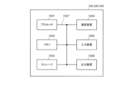
- FIG. 2 is a diagram illustrating an example of a hardware configuration of a base station, a terminal, and a wireless device according to an embodiment of the present disclosure.
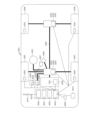
- FIG. 1 is a diagram illustrating an example of a configuration of a vehicle.
- existing technologies are used as appropriate.
- the existing technologies are, for example, existing LTE or existing NR, but are not limited to existing LTE and NR.
- SS Synchronization signal
- PSS Primary SS
- SSS Secondary SS
- PBCH Physical broadcast channel
- PRACH Physical random access channel
- PDCCH Physical Downlink Control Channel
- PDSCH Physical Downlink Shared Channel
- PUCCH Physical Uplink Control Channel
- PUSCH Physical Uplink Shared Channel
- NR corresponds to NR-SS, NR-PSS, NR-SSS, NR-PBCH, NR-PRACH, etc.
- NR- even if a signal is used in NR, it is not necessarily specified as "NR-".
- the duplex method may be a TDD (Time Division Duplex) method, an FDD (Frequency Division Duplex) method, or another method (e.g., Flexible Duplex, etc.).
- TDD Time Division Duplex
- FDD Frequency Division Duplex
- another method e.g., Flexible Duplex, etc.
- “configuring" wireless parameters and the like may mean that predetermined values are pre-configured, or that wireless parameters notified from a base station or terminal are configured.
- ⁇ Wireless communication system> 1 is a diagram illustrating an example of a wireless communication system 10 according to an embodiment of the present disclosure.
- the wireless communication system 10 is a wireless communication system conforming to 5G NR or 6G NR, and includes a Next Generation-Radio Access Network 20 (hereinafter, NG-RAN 20) and a terminal 200 (hereinafter, also referred to as UE (User Equipment) 200).
- NG-RAN 20 Next Generation-Radio Access Network 20
- UE User Equipment
- the wireless communication system 10 may be a wireless communication system conforming to a method called Beyond 5G, 5G Evolution, or 6G.
- NG-RAN 20 includes a base station 100 (hereinafter also referred to as gNB 100). Note that the number of gNBs and UEs is not limited to the example shown in FIG. 1.
- NG-RAN 20 actually includes multiple NG-RAN nodes, specifically, gNBs (or ng-eNBs), and is connected to a core network conforming to 5G or 6G.
- gNBs or ng-eNBs
- NG-RAN 20 and the core network may simply be expressed as a "network.”
- gNB may be read as a network (NW).
- the gNB 100 is, as an example, a base station conforming to 5G or 6G and performs wireless communication conforming to 5G or 6G with the UE 200.
- a radio device 300 that transfers signals between the gNB 100 and the UE 200 is shown.
- the radio device 300 may be referred to as a RIS (Reconfigurable Intelligent Surface).
- the wireless device 300 performs a forwarding operation to forward, for example, a signal transmitted from the gNB 100 to the UE 200.
- the wireless device 300 may also perform a forwarding operation to forward a signal transmitted from the UE 200 to the gNB 100.
- forward may be replaced with “relay.”
- operation may be replaced with “processing,” “control,” etc.
- the RIS which is an example of the wireless device 300 being considered in NR, will be described below.
- the gNB 100 and UE 200 may support MIMO (Multiple-Input Multiple-Output), which generates more directional beams by controlling radio signals transmitted from multiple antenna elements, carrier aggregation (CA: Carrier Aggregation), which bundles and uses multiple component carriers (CC: Component Carriers), and dual connectivity (DC: Dual Connectivity), which communicates between the UE and each of two NG-RAN nodes.
- MIMO Multiple-Input Multiple-Output
- CA Carrier Aggregation
- CC Component Carriers
- DC Dual Connectivity
- the wireless communication system 10 may be compatible with a plurality of frequency ranges (FR).
- the wireless communication system 10 may be compatible with FR1 and FR2.
- the frequency bands of each FR are, for example, as follows: ⁇ FR1: 410MHz to 7.125GHz ⁇ FR2: 24.25GHz to 52.6GHz
- FR1 may use a sub-carrier spacing (SCS) of 15 kHz, 30 kHz or 60 kHz, and a bandwidth (BW) of 5 to 100 MHz.
- FR2 is a higher frequency than FR1, and may use an SCS of 60 kHz or 120 kHz (which may include 240 kHz), and a bandwidth (BW) of 50 to 400 MHz.
- SCS may also be interpreted as numerology. Numerology is defined in 3GPP TS 38.300 and corresponds to one subcarrier spacing in the frequency domain.
- the wireless communication system 10 may support a higher frequency band than the FR2 frequency band. Specifically, the wireless communication system 10 may support a frequency band exceeding 52.6 GHz up to 114.25 GHz. Such a high frequency band may be referred to as "FR2x" for convenience.
- FR2x frequency band exceeding 52.6 GHz
- CP-OFDM Cyclic Prefix - Orthogonal Frequency Division Multiplexing
- DFT-S-OFDM Discrete Fourier Transform - Spread - Orthogonal Frequency Division Multiplexing
- the time direction (t) may be referred to as the time domain, symbol period, or symbol time, etc.
- the frequency direction may be referred to as the frequency domain, resource block, subcarrier, bandwidth part (BWP), etc.
- the gNB100 transmits control information, configuration information, etc. of the gNB100 to the UE200 as a downlink (DL) signal.
- DL downlink
- gNB100 receives control information, data signals, information regarding the processing capabilities of UE200 (terminal capabilities (information); for example, UE capability), etc., from UE200 as uplink (UL) signals.
- the wireless device 300 performs a forwarding operation to forward the DL signal to the UE 200.
- the wireless device 300 also performs a forwarding operation to forward the UL signal to the gNB 100.
- the UL signal that the gNB 100 receives from the UE 200 and/or the DL signal that the UE 200 receives from the gNB 100 may be a signal forwarded by the wireless device 300.
- UE200 is a communication device equipped with wireless communication capabilities, such as a smartphone, mobile phone, tablet, wearable device, or M2M (Machine-to-Machine) communication module.
- wireless communication capabilities such as a smartphone, mobile phone, tablet, wearable device, or M2M (Machine-to-Machine) communication module.
- UE200 receives control signals or data signals from gNB100 on DL and transmits control signals or data signals to gNB100 on UL to utilize various communication services provided by wireless communication system 10.
- UE200 also receives various reference signals transmitted from gNB100 and performs measurement of propagation path quality based on the reception results of the reference signals.
- Channels used to transmit DL signals include, for example, data channels and control channels.
- the data channel may include a physical downlink shared channel (PDSCH)
- the control channel may include a physical downlink control channel (PDCCH).
- PDSCH is an example of a downlink shared channel
- PDCCH is an example of a downlink control channel.
- PDCCH may be interpreted as downlink control information (DCI), control information, etc. transmitted in PDCCH.
- the reference signals included in the DL signal may include, for example, at least one of DMRS (Demodulation Reference Signal), PTRS (Phase Tracking Reference Signal), CSI-RS (Channel State Information - Reference Signal), SRS (Sounding Reference Signal), and PRS (Positioning Reference Signal) for position information.
- DMRS Demodulation Reference Signal
- PTRS Phase Tracking Reference Signal
- CSI-RS Channel State Information - Reference Signal
- SRS Sounding Reference Signal
- PRS Positioning Reference Signal
- Channels used to transmit UL signals include, for example, data channels and control channels.
- the data channel may include a physical uplink shared channel (PUSCH)
- the control channel may include a physical uplink control channel (PUCCH).
- PUSCH is an example of an uplink shared channel
- PUCCH is an example of an uplink control channel.
- the shared channel may be called a data channel.
- PUSCH or PUCCH may be interpreted as uplink control information (UCI), control information, etc. transmitted in PUSCH or PUCCH.
- the reference signal included in the UL signal may include, for example, at least one of DMRS, PTRS, CSI-RS, SRSRS, and PRS for location information.
- reference signals such as DMRS and PTRS are used to demodulate the UL data signal and are transmitted using the PUSCH.
- NR MIMO NR MIMO
- LOS-MIMO a very large bandwidth is required to achieve a data rate of 100 Gbps, which is difficult to secure.
- LOS-MIMO schemes that have already been considered require fixed transmitting and receiving positions, making them unsuitable for access links or requiring too large array sizes.
- the RIS may control the direction of the reflected signal or the direction of the transmitted (refracted) signal.
- reflection, transmission, and refraction may be interpreted as interchangeable.
- reflection, transmission, and refraction of a signal at a RIS may be understood as the RIS receiving a signal transmitted from a specific direction and transmitting (or) a signal in the same direction as the specific direction or in a direction different from the specific direction.
- the signal transmitted by the RIS may be the same signal as the signal received by the RIS, or may be a signal received by the RIS that has been subjected to specific processing.
- forwarding processing at a RIS may be understood as processing in which at least one of reflection, transmission, and refraction occurs at the RIS.
- RIS can provide beam gain with narrowband beams, an increase in the number of RIS beams (beams reflected/refracted by the RIS) is required.
- the RIS may be installed on objects such as buildings.
- FIG. 3A is a diagram showing an example of communication using the NCR configuration.
- the NCR may include an NCR-mobile termination (MT) and an NCR-forwarding (Fwd).
- the NCR-MT communicates with the BS (gNB) via a control link.
- gNB BS
- Communication between the NCR-MT and the BS may include at least one of receiving configuration/instruction/control information from the BS and sending requests/reports/responses to the BS.
- the NCR-Fwd relays communications between the BS and the UE by relaying/amplifying from the backhaul link to the access link and from the access link to the backhaul link.
- FIG. 3B is a diagram showing an example of communication using a RIS.
- the RIS relays communication between the BS and the UE by controlling the reflection angle in at least one of the reflection from the backhaul link to the access link and the reflection from the access link to the backhaul link.
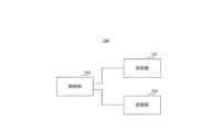
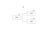
- FIG. 4 is a diagram showing an example of a system architecture including a RIS.
- the system architecture including a RIS will be described below with reference to Fig. 4, but this is merely an example.
- a system architecture including a RIS may include multiple (e.g., two) design phases.
- a system architecture including a RIS may include an aperture pre-adaptation phase.
- UE positioning may be performed first.
- the UE may report information about the UE's position/attitude to the network (NW).
- the NW base station
- the NW may estimate information about the UE's position/attitude based on a signal (e.g., UL RS) transmitted from the UE.
- UE positioning during the aperture pre-adaptation phase may be omitted.
- pre-adaptation of the aperture e.g., antenna elements
- pre-adaptation of the aperture e.g., antenna elements
- aperture adaptation may mean determining/determining/selecting which antenna elements/arrays to use.
- pre-adaptation of the BS aperture e.g., antenna elements
- the system architecture including the RIS may also include a beamforming phase.
- the beamforming phase may, for example, follow an aperture pre-adaptation phase.
- beamforming may first be performed at the BS.
- Beamforming may then be performed in the RIS during the beamforming phase.
- reception by the UE may occur in the beamforming phase.
- the UE may use a CSI reception (CSIR) based MIMO receiver.
- CTR CSI reception
- UE reception during the beamforming phase may be omitted.
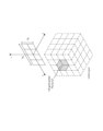
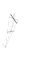
- FIG. 5 is a diagram showing an example of the near field (NF) and far field (FF) of a RIS.
- FIG. 5 illustrates an example of a RIS array, radio wave propagation in the near field for the RIS array, and radio wave propagation in the far field.
- the RIS array may be regarded as an example of a surface in the RIS that transmits signals or a surface that radiates radio waves.
- the near field may also be replaced with a near distance.
- the far field may also be replaced with a far distance.
- a large aperture of the RIS exhibits certain characteristics that increase the range of the near field.
- a large aperture of the RIS increases the range of the near field because the boundary of the near field (e.g., the boundary between the near field and the far field) is proportional to the square of D, where D indicates the size associated with the aperture of the RIS.
- the boundary of the near field is inversely proportional to the wavelength ⁇ , so the shorter the wavelength, i.e., the higher the frequency, the larger the range of the near field.
- the phase delays for the various elements of the RIS become distinguishable. As a result, the assumption of a plane wavefront is not valid and spherical wavefronts must be considered.
- the radio waves emitted from each element of the RIS are assumed to be plane waves, but in the near field region, the wavefronts of the radio waves arising from each element are spherical.
- the beamforming method may be DFT-based beamforming (BF), beamfocusing with optimum phase, and beamfocusing with near-field (NF) steering vector.
- BF DFT-based beamforming
- NF near-field
- DFT-based BF may be used primarily for transmitting signals to terminals at long distances.
- DFT-based BF may use a precoder (matrix) based on angle-dependent linear phase.
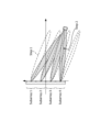
- Figure 6A shows an example of DFT-based beamforming (BF). Note that Figure 6A shows an example of a uniform linear array. In this example, xn is the distance from the array center to element n in the array and the angle of the beam with respect to the axis normal to the array.
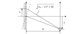
- Beam focusing with optimal phase may be used primarily for transmitting signals to terminals in close range. Beam focusing with optimal phase may use a precoder (matrix) based on position (distance)-dependent non-linear phase.
- Figure 6B shows an example of beam focusing with optimal phase. Note that Figure 6B shows an example of a uniform linear array.
- DF is the focal length and x' is the distance from the axis perpendicular to the array to the focal point.
- Beam focusing with short-range steering vectors may be used primarily for transmitting signals to short-range terminals. Beam focusing with short-range steering vectors may use a precoder (matrix) based on angle- & position (distance)-dependent quadratic phase.
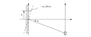
- Figure 6C shows an example of beam focusing with a near field (NF) steering vector. Note that Figure 6C shows an example of a uniform linear array. In this example, D is the distance from the center of the array to the focal point, and ⁇ is the angle from an axis normal to the array to a line connecting the array center and the focal point.
- NF near field
- DFT codebooks Traditional codebooks for far-field beamforming, such as DFT codebooks, cannot be directly applied to the near-field due to a mismatch with the near-field channel. If DFT codebooks were applied to near-field beamforming, it could cause severe SNR loss.
- focused beamforming such as ring-type codebooks (RTC), which are a near-field form of the coherent beamformer, does not have the near-field limitation.
- RIS is adopted for data channel transmission
- the RTC described above generates a UE-specific focused beam, enabling high-speed transmission.
- Figure 7 is a diagram showing an example of SSB forwarding with RIS applied.
- Figure 7 shows that of SSBs #0 to #4 transmitted by the gNB, the RIS forwards SSBs #2 to #4.
- the RIS When the RIS transmits a control channel (e.g., SSB, etc.), it is considered to expand the beam to transmit the data.
- a control channel e.g., SSB, etc.
- ⁇ Existing methods> The following describes an existing method of SSB transmission by a RIS.
- the RIS utilizes multiple narrow beams to transmit the SSB transmitted by the gNB. Therefore, the existing method requires a significant allocation of SSB resources or a significant change to the SSB scheme.
- Typical existing beam expansion techniques can be categorized into numerical optimization algorithm-based techniques, aperture adjustment-based techniques, logical subarray division-based techniques, and wide-area illumination approaches.
- the beamforming gain of the array is reduced due to the aperture adjustment.
- technologies based on logical subarray division can result in large variations in beamforming gain across the entire area.
- the first example concerns codebook/precoder design.
- the codebook/precoder may be a codebook/precoder for short distance (NF) or a codebook/precoder for long distance (FF).
- a short distance may mean a distance less than (or equal to) a particular threshold.
- a long distance may mean a distance greater than (or equal to) a particular threshold.
- the RIS may receive information for the precoder/codebook from the NW.
- the information may be, for example, information about the location of another node (e.g., a UE/NW node).
- the information about the location may be, for example, at least one of information about angle and information about distance.
- the first example is broadly divided into examples 1-1 and 1-2.
- Example 1-1 or example 1-2 may be applied, or a combination of examples 1-1 and 1-2 may be applied.
- Example 1-1 relates to a specific codebook/precoder design.
- Example 1-1 is broadly divided into Examples 1-1-1 to 1-1-4. Any of Examples 1-1-1 to 1-1-4 may be applied, or at least two of Examples 1-1-1 to 1-1-4 may be applied in combination.
- the precoder may be calculated, for example, as the output of a specific multiplication of multiple different precoders/matrices.
- codebook precoder
- codeword matrix
- term term, vector, and element
- the precoder in the RIS may be a precoder that provides decoupling of the angle-dependent and distance (position)-dependent terms.
- Example 1-1-1 may be used, for example, for beamforming/focusing of NCR including RIS (RIS-NCR).
- the precoder in RIS may be calculated, for example, by the product (e.g., Hadamard product, e.g., element-wise product) of a distance-dependent precoder/matrix (e.g., WRing) and an angle-dependent precoder/matrix (e.g., WDFT).
- product e.g., Hadamard product, e.g., element-wise product
- a distance-dependent precoder/matrix e.g., WRing
- an angle-dependent precoder/matrix e.g., WDFT
- the precoder may be calculated using Equation 1 below.
- D F may be the axial distance between the array and the focal position.
- phase shift associated with the distance-dependent precoder may be referred to as a ring-type phase distribution.
- codebook associated with the distance-dependent precoder may be referred to as a ring-type codebook (RTC).
- FIG. 8 is a diagram showing an example of a precoder according to Example 1-1-1.
- a precoder according to Example 1-1-1.
- FIG. 8 an example of a uniform and linear array is shown.
- first, beam focusing at the boresight is performed.
- the above-mentioned distance-dependent precoder may be used for the beam focusing.
- k is an index corresponding to the phase in the DFT.
- the focal position is then shifted by the DFT vector.
- the above-mentioned angle-dependent precoder may be used for this shifting.
- Example 1-1-1 by using angle-dependent terms and distance (position)-dependent terms, it is possible to transmit signals appropriately to targets at long and short distances, and it is also easy to implement.
- the precoder in the RIS may be a precoder that utilizes piecewise linear approximation with DFT vectors.
- the precoder may be a precoder that includes terms for each subarray (one or more arrays) and distance (position) dependent terms.
- Example 1-1-2 may be used, for example, for beamforming/focusing of an NCR including a RIS (RIS-NCR) and/or coherent transmission of multiple panels (e.g., widely spaced panels).
- RIS-NCR RIS-NCR
- panels e.g., widely spaced panels
- Example 1-1-2 is suitable for subarray-based RIS-NCR.
- the precoder in the RIS may be calculated, for example, by the product (e.g., the Hadamard product (e.g., element-wise product)) of a precoder for each subarray (one or more arrays) and an angle-dependent precoder.
- the product e.g., the Hadamard product (e.g., element-wise product)
- the angle-dependent precoder may be calculated, for example, by the product (e.g., the Hadamard product (e.g., element-wise product) of a precoder for each subarray (one or more arrays) and an angle-dependent precoder.
- the precoder for each subarray may be expressed, for example, as the product of the phase offset for each subarray and the angular offset of the subarray.
- the precoder may be calculated using Equation 2 below.
- ⁇ (i,j) PO may indicate the phase offset of subarray (i,j), which may be quantized with specific bits (e.g., b bits) that may take on specific values (e.g., values from 0 to 2 ⁇ ), and W (i,j) AO may indicate the angle offset of subarray (i,j).
- W(i,j)AO may be calculated based on the dot product of the vector from the array reference point to the reference point of subarray (i,j) and the vector from the reference point of subarray (i,j) to antenna element (m,n) in subarray (i,j).
- W (i,j) AO may be calculated by the following Equation 3.
- D may be the distance from the array (e.g., the array reference point) to the target (e.g., the UE)
- r (i,j) SA may denote the vector from the array reference point to the subarray (i,j) reference point
- r (m,n) AE may denote the vector from the subarray (i,j) reference point to the antenna element (m,n) in subarray (i,j) (see FIG. 9).
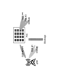
- FIG. 10 is a diagram showing an example of a precoder according to Example 1-1-2.
- FIG. 10 shows an example of a uniform and linear array.
- focusing of the beam direction is performed for multiple arrays (each subarray) using phase offsets (step 1).
- phase offsets step 1
- a precoder based on the above-mentioned phase offset and angle offset may be used.
- the focal position is then shifted by the DFT vector (step 2).
- the above-mentioned angle-dependent precoder may be used for this shifting.
- Example 1-1-2 by using terms for each subarray (one or more arrays) and distance (position) dependent terms, it is possible to transmit signals appropriately to targets at long and short distances.
- the precoder in the RIS may be a precoder in which a term relating to short distance and a term relating to long distance are utilized.
- Example 1-1-3 may be used, for example, to acquire CSI in either or both of FF and NF (not limited to FF and NF), or may be used for localization/sensing of NF.
- the precoder in the RIS may be calculated, for example, by multiplying a first precoder by a second precoder (e.g., a Kronecker product, e.g., an element-wise product).
- the first/second precoder may include a term corresponding to a long distance (or angle dependency) and a term corresponding to a short distance (or distance dependency).
- the precoder in this example may be applied in a uniform planar array.
- the precoder W may be expressed by the following Equation 4.
- W is expressed as the Kronecker product of the first precoder W N_1, O_1, k_1, D, L_1 and the second precoder W N_2, O_2, k_2, D, L_2 .
- N_1 represents “N 1 ".
- Other notations besides “N_1” may also be expressed in the same way as “N_1”.
- W N_i, O_i, k_i, D, L_i may be expressed, for example, by the following Equation 5.
- the number of antenna elements (scattering elements) N i in the i-th axial direction in the RIS array and the oversampling number O i in the i-th axial direction may be the same as the NR DFT-based codebook defined in the existing NR.
- k i may be a codeword index
- k′ may represent a quadratic term.
- d RP -d 0 may represent the distance between a particular antenna element (eg, antenna element #0) and a reference point, and ⁇ d may represent the antenna element spacing.
- NRP may be 0 if the bottom left most element of the array is taken as the reference point.
- N RP may be calculated as N i ⁇ 1.
- D may represent the normalized distance between the reference point and the focal length.
- D may be calculated as (focal length)/ ⁇ .
- L may be a value related to the normalized equivalent aperture. L may be calculated, for example, as ON ⁇ d/ ⁇ .
- the precoder in the RIS may be a precoder that is used for the access link (between the UE and the RIS) and a precoder for the backhaul link (between the BS and the RIS).
- the precoder may be a precoder that includes terms for each subarray (one or more arrays) and distance (position) dependent terms.
- Example 1-1-4 may be used, for example, for beamforming/focusing of NCR including RIS (RIS-NCR) of the backhaul link/access link, and/or cascaded LoS-MIMO (e.g., LoS-MIMO requiring joint focal points indication).
- RIS-NCR RIS-NCR
- LoS-MIMO e.g., LoS-MIMO requiring joint focal points indication
- the precoder in the RIS may be calculated, for example, by the product (e.g., the Hadamard product (e.g., element-wise product)) of the precoder for the access link and the precoder for the backhaul link.
- the product e.g., the Hadamard product (e.g., element-wise product)
- the precoder may be calculated using the following Equation 6.
- W AC may indicate a precoder of a beam (access beam, beam for UE) in an access link of the RIS-NCR
- W BH may indicate a precoder of a beam (backhaul beam, beam for BS) in a backhaul link of the RIS-NCR.
- At least one of W AC and W BH may be, for example, a precoder calculated by at least one of the methods described in Examples 1-1-1 to 1-1-3 above.
- the focal lengths of W AC and W BH may be selected/determined independently or jointly.
- the focal lengths of W AC and W BH may be selected/determined in a conjugate symmetric manner.
- Example 1-1-4 it is possible to appropriately design the precoder/codebook not only for the access link but also for the backhaul link.
- L may be a parameter related to an aperture (e.g., an antenna element). L may be reported as a capability of the RIS-NCR (NCR-MT).
- L may be reported by the RIS, for example, as antenna number/spacing in n dimensions (e.g., n is 2).
- L may be reported by the RIS, for example, as the length of a side of the RIS (e.g., antenna number x antenna spacing).
- Ni , Oi , kj , kip , and Di may be parameters related to the codebooks of the access link/backhaul link.
- Ni and Oi may be associated with a codebook of the RIS, which may be preset for the RIS or may be predefined in a specification.
- N i and O i may be determined based on reports of the capabilities of the RIS or may be determined independently of the dimensionality of the RIS.
- the k i may be associated with a codebook of the RIS, which may be indicated to the RIS.
- the kip may be calculated at the RIS based on specific settings/instructions for the RIS.
- D1 may be preconfigured by the BS for the RIS, and D2 may be instructed by the BS for the RIS.
- D1 and D2 may be commanded by the BS (using a compound CW).
- D1 may be preconfigured by the BS for the RIS, and D2 may be measured by the RIS.
- D1 and D2 may be measured by RIS.
- logarithmic quantization may be used in determining D1 and D2 .
- NRP may be a parameter related to the reference point of the RIS.
- NRP may be, for example, a parameter related to the offset of the reference point of the RIS.
- the NRP may be associated with a codebook of the RIS, which may be indicated to the RIS.
- a RIS reference point may refer to a specific location.
- the reference point for the RIS may be the location of an antenna/subarray at a particular location (e.g., bottom-left extreme).
- the reference point for the RIS may be the location of the center point of the RIS, which is suitable for a single large RIS or multiple separate sub-arrays.
- the RIS reference point may be reported by the RIS.
- the RIS reference point may be determined according to the reference point reported by the RIS.
- Parameters indicating an adaptation (aperture adaptation) mode may be defined. These parameters may be used for aperture control of the RIS.
- the parameter indicating the adaptation mode may be associated with a codebook of the RIS.
- the codebook of the RIS may be indicated to the RIS.
- Parameters may be defined that indicate the shape/size of the RIS. These parameters may be used to control the aperture of the RIS.
- the parameters indicating the shape/size of the RIS may be associated with a codebook of the RIS.
- the codebook of the RIS may be indicated to the RIS.
- the parameters may be indicated by a bitmap.
- the parameters may also be indicated by the direction and length of two sides of the aperture forming a parallelogram.
- the parameters may also be indicated by the arrangement of the subarrays (e.g., direction/spacing/subarray number/subarray size).
- the parameters may also be indicated by at least one of the direction/length of two sides of the aperture forming a parallelogram (which may be called the general mode), the subarray number (sampling rate), and the subarray size.
- a parameter may be specified indicating the roll-off factor.
- Parameters for conjugate symmetric RTC may be defined.
- the parameters may be parameters for a reference point for the UE's location.
- the reference point for the UE's location may, for example, refer to an antenna port of a particular UE (e.g., antenna port #0).
- the reference point for the UE's location may refer, for example, to a specific (e.g., central) UE array established by the BS.
- Example 1-2 describes quantization of angle (angle information) and distance (distance information) in codebook notification (to NW/RIS-NCR).
- Example 1-2 is broadly divided into Examples 1-2-1 and 1-2-2. Either of Examples 1-2-1 and 1-2-2 below may be applied, or Examples 1-2-1 and 1-2-2 below may be applied in combination.
- the NW may transmit angle information/distance information regarding the codebook/precoder quantized using at least one of examples 1-2-1 and 1-2-2 to the RIS-NCR (or NW).
- linear quantization may be used for distance. Using linear quantization makes it easier to implement in the device.
- logarithmic quantization may be used for distance. Using logarithmic quantization makes it possible to perform appropriate quantization regardless of whether the distance between the devices is long or short.
- Quantization of the distance may be performed using Equation 7 below.
- the range of NF may be related to the array area.
- the range of NF may be (approximately) proportional to the array area.
- the quantization of angles and distances may use a uniform grid in Cartesian coordinates (angles and distances may be quantized on a uniform grid). In this case, it is suitable for use in localization/position-based beam focusing.
- quantization of angles and distances may use a non-uniform grid in spherical coordinates (angles and distances may be quantized on a non-uniform grid). This is favorable in terms of aperture/NF range at boresight, and allows for more uniform coverage and fewer beams by using wider beams at close range.
- FIG. 11 shows an example of a uniform grid in Cartesian coordinates.
- RIS-NCR uniform grid in Cartesian coordinates for RIS
- (x gi , y gi , z gi ) may denote the center coordinates of the i-th grid obtained from the grid index i.
- the uniform grid RTC may be calculated according to at least one of the following options 1 and 2:
- the RTC using a uniform grid may be calculated using Equation 9 below (option 1).
- the RTC using a uniform grid may be calculated using Equation 10 below (option 2).
- ⁇ may represent the azimuth angle and ⁇ may represent the elevation angle.
- ⁇ and ⁇ may be obtained by a specific coordinate transformation.
- the angle (angle information) and distance (distance information) can be appropriately quantized in the codebook notification.
- the second example is broadly divided into examples 2-1 and 2-2.
- the following examples 2-1 or 2-2 may be applied, or the following examples 2-1 and 2-2 may be applied in combination.
- the RIS-NCR may receive information (setting information) related to the control of apertures (e.g., antenna elements) from the NW. Based on the information, the RIS-NCR may determine the aperture/antenna element to be used for signals destined for the terminal.
- information setting information
- the RIS-NCR may determine the aperture/antenna element to be used for signals destined for the terminal.
- the RIS may select/decide/determine which aperture to use from among the apertures included in the RIS.
- Example 2-1 is broadly divided into Examples 2-1-1 and 2-1-2. The following Examples 2-1-1 or 2-1-2 may be applied, or the following Examples 2-1-1 and 2-1-2 may be applied in combination.
- Unnecessary RIS elements e.g., antenna elements
- Information regarding this setting may be included in information regarding aperture control received from the NW.
- Beamforming and aperture adaptation may also be used in combination.
- the beamforming information may include, for example, information regarding the beamforming vector of the RIS.
- the (desired, actually used) aperture may be represented by a value (e.g., an aperture function) indicating the on/off state of each RIS element.
- the (desired, actually used) aperture may be applied to the beamforming vector of that RIS.
- a value (e.g., an aperture function) corresponding to a RIS element when a value (e.g., an aperture function) corresponding to a RIS element is a first value (e.g., 0), the RIS element may be in an off state. Also, when a value (e.g., an aperture function) corresponding to a RIS element is a second value (e.g., 1), the RIS element may be in an on state.
- Aperture adaptation may be used to control the beam shape (e.g., at least one of the beam width, side lobes, main lobe, and focal spot shape/size).
- Example 2-2 aperture control in RIS (RIS-NCR) will be described.
- Example 2-2 is broadly divided into Examples 2-2-1 and 2-2-2.
- the following Examples 2-2-1 or 2-2-2 may be applied, or the following Examples 2-2-1 and 2-2-2 may be applied in combination.
- a mode for the aperture of the RIS-NCR may be defined.
- the RIS-NCR may determine the aperture to use based on the mode.
- the mode may include, for example, first to third modes.
- the first mode may be a mode in which some/all of the elements of the RIS are used in a square shape.
- the first mode may be called, for example, a fallback mode.
- the second mode may be, for example, a mode in which some of the RIS elements are used in a parallelogram (diamond) shape.
- the second mode may be, for example, called a semi-continuous mode.
- the third mode may be a mode in which only a specific RIS is used among the RIS elements.
- the specific RIS may be determined by selecting a portion of the RIS elements in a parallelogram (diamond) shape.
- the third mode may be called, for example, a discrete mode.
- Example 2-2-2> The shape/size of the aperture of the RIS-NCR to be used may be instructed in a specific manner, and information regarding the instruction may be included in the information regarding aperture control received from the NW.
- the shape/size of the aperture of the RIS-NCR used may be determined by a bitmap/parameter indicating the on/off state of the RIS elements used.
- the shape/size of the aperture in the second/third modes may be indicated in a specific manner.
- the specific manner may be based on the length and angle of two sides relative to a specific point (e.g., a reference point) of the RIS element (selected RIS element).
- the size/number of subarrays to be used may additionally be indicated.
- the RIS elements/apertures to be used can be appropriately determined/selected.
- the first issue is that the RIS has a large aperture, which narrows the beam width of UE-specific beamforming, making it difficult to effectively cover a wide area.
- a significant allocation of SSB resources will be required, or a significant change will be required to the SSB scheme. If the allocation of SSB resources increases, the allocation of resources to other channels (or signals) will decrease in comparison, leading to a decrease in the throughput of the entire system and a decrease in the efficiency of resource utilization. If a significant change is made to the SSB scheme, it will also require a significant change in the gNB and/or UE, making it difficult to maintain compatibility between versions, etc.
- existing schemes require a significant number of SSBs to be available for the gNB to send to the RIS for forwarding, while the total availability of SSBs (e.g., the number of available SSB resources) is limited. For example, in the case of a RIS with a size of 0.64m x 0.64m and operating at 30GHz covering a range of ⁇ 45° including near and far fields, approximately 300 narrow beams are required. Note that in this case, the 3dB beamwidth of the narrow beams is 0.79°.
- the beam width of the UE-specific beam specified by the codebook is very narrow, it is difficult to cover the area directly, and when the RIS transmits SSB using a narrow beam, a significant portion of the limited SSB resources is consumed. In view of this, in this embodiment, the generation of a wide beam is considered.
- a codebook-based instruction method for generating a wide beam of a RIS is described. Also, in this embodiment, a method for transmitting a control channel based on a wide beam is described, by way of example.
- an "instruction” for a certain function may indicate information for performing that function (or operation), or may indicate an operation such as transmitting (or notifying) information for performing that function (or operation).
- "instruction” may be replaced with an indication, indicator, information, parameter, etc.
- a beam instruction may indicate information for performing beam control, or may indicate an operation such as transmitting (or notifying) information for performing beam control.
- the following proposal describes the generation of a wide beam in the near field based on the selection of control information for beam generation.
- the control information for beam generation can be, for example, a code word included in the RTC (hereinafter referred to as RTC code word).
- RTC code word a code word included in the RTC
- the RTC enables wide beam generation without requiring additional special code word generation.
- the RIS can generate wide beams of any shape.
- the codeword selection may be based on the geometric relationship between the RIS and the target area.
- the RTC codeword may be selected based on at least one of three parameters: the dimension of the target area, the angle, and the distance between the center of the target area and the center of the RIS array.
- Proposal 1 describes near-field wide beam generation based on RTC codeword selection.
- the focal position corresponding to the wide beam is determined based on the geometric optics principle.
- the focal position is calculated based on the geometric relationship between the RIS and the target area.
- the focal position may be referred to below as the focal position or focal point.
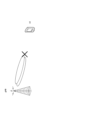
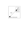
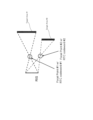
- FIG. 12A is a diagram showing a first example of calculation of the focal position.
- FIG. 12B is a diagram showing a second example of calculation of the focal position.
- surface D indicates the surface of the RIS array
- surface L indicates the target area.
- the RIS array may be an example of a radiation surface from which a signal (or radio wave) from the RIS is emitted.
- Distance d indicates the distance between the center of surface D and the center of surface L.
- Angle ⁇ indicates the angle between surface D and a surface perpendicular to the line connecting the center of surface D and the center of surface L.
- Angle ⁇ indicates the angle between surface L and a surface perpendicular to the line connecting the center of surface D and the center of surface L.
- FIG. 12A is a diagram showing a first example of calculation of the focal position.
- FIG. 12B is a diagram showing a second example of calculation of the focal position.
- surface D indicates the surface of the RIS array
- surface L indicates the target area.
- distance F indicates the distance between the center of surface D and the actual focal position P
- distance F indicates the distance between the center of surface D and the virtual focal position P.
- the distance F between the focal position and the RIS array i.e., surface D
- the focal length may be referred to as the focal length.
- the actual focal position may be calculated as the focal position.
- the distance F from the center of the surface D to the focal position P is expressed by the formula (12).
- the position that is perpendicular to the center of surface D (i.e., the center of the RIS array) and a distance F in the direction of surface L (i.e., the direction of the target area) is determined to be the actual focal position.
- the focal position is calculated based on an example of the geometric relationship between the RIS array and the target area, such as the position and size of the RIS array, the position and size of the target area, and an angle difference determined by the positional relationship between the RIS array and the target area.
- a virtual focal position may be calculated as the focal position.
- a distance F from the center of a surface D to a focal position P is expressed by equation (13).
- a position that is a distance F away vertically from the center of surface D (i.e., the center of the RIS array) in the opposite direction to the direction of surface L (i.e., the opposite direction to the direction of the target area) is determined to be the virtual focal position.
- the focal position is calculated based on an example of the geometric relationship between the RIS array and the target area, such as the position and size of the RIS array, the position and size of the target area, and an angle difference determined by the positional relationship between the RIS array and the target area.
- Whether to calculate the actual focal position or the virtual focal position may be stipulated by the specifications, or may be determined by an instruction from the network. Whether to calculate the actual focal position or the virtual focal position may be dynamically switched or may be fixed.
- an RTC codeword is selected according to (based on) the calculated focal position. For example, an RTC codeword is selected that achieves radio wave emission with a focal point that coincides with (or is close to) the calculated focal position. Note that instead of selecting an RTC codeword according to the focal position, an RTC codeword may be selected according to the focal distance F.
- the selection method is not particularly limited.
- focal positions and RTC code words may be associated with each other, and an RTC code word may be selected based on this association.
- information indicating the RTC code word e.g., an index associated with the code word
- the focal position may be quantized, and an RTC code word associated with the quantized focal position may be selected.
- the focal position may be classified into one of a finite number of groups, and an RTC code word corresponding to the classified group may be selected.
- the codeword to be selected may be changed depending on the focal position (or focal length). For example, if the focal position (or focal length) is within a predetermined range, the target area may be determined to be within the near field, and an RTC codeword may be selected. Also, for example, if the focal position (or focal length) is not within a predetermined range, the target area may be determined to be within the far field, and a codeword for beam generation in the far field (e.g., a codeword from a DFT codebook) may be selected.
- a codeword for beam generation in the far field e.g., a codeword from a DFT codebook
- steps 1 and 2 described above may be performed by the RIS, or at least one may be performed by the RIS and the rest may be performed by the network (e.g., gNB).
- the network e.g., gNB
- parameters related to the processes performed by the RIS may be provided by the network.
- both of the two processes may be performed by the network, and the RIS may generate a wide beam in response to instructions from the selected RTC codeword.
- FIG. 12C is a diagram showing an example of a wide beam that is generated.
- FIG. 12C shows that SSB#N transmitted from a gNB is forwarded by a RIS.
- a wide beam that covers a target area can be generated to transmit SSB#N.
- an RTC codeword for a near-field wide beam covering the target area can be appropriately selected.
- the RTC codeword is selected so that the focal position is set between surface D (radiation surface) and surface L (target area), or in the area opposite surface L across surface D. Therefore, a near-field wide beam can be appropriately generated.
- Proposal 2 an example of a method for shaping a wide beam is described.
- the shaping of the wide beam may be a control of the shape of the wide beam based on the shape of the target area covered by the wide beam.
- the generation of a multi-wide beam, the control of the operation mode of the RIS, and a phase mask are described as examples of the shaping of the wide beam.
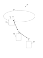
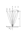
- Fig. 13 is a diagram showing an example of multi-wide beam generation.
- Fig. 13 shows an example of a RIS that generates beams for two target areas, target area #1 and target area #2.
- step 1 of generating a multi-wide beam the focal position is calculated based on the geometric relationship between the RIS and the target area.
- the method of calculating the focal position may be the same as in Proposal 1 described above. However, in Proposal 2-1, the focal position is calculated for each of the multiple target areas, as shown in FIG. 13.
- the RIS selects multiple RTC codewords for the wide beam according to the target beam shape.
- the RIS selects RTC codeword #1 according to the beam shape covering target area #1 according to focus #1 on target area #1.
- the RIS selects RTC codeword #2 according to the beam shape covering target area #2 according to focus #2 on target area #2.
- one RTC code word for one focus may be selected in the same manner as in Proposal 1 described above.
- step 3 of generating the multi-wide beam the RIS performs complex superposition of the selected codewords to obtain a multi-beam codeword.
- complex superposition of RTC codeword #1 and RTC codeword #2 is performed to obtain a multi-beam codeword.
- the multi-beam codeword may be a codeword that generates multiple beams.
- a codeword that generates multiple wide beams may be referred to as a multi-wide beam codeword.
- n is an integer equal to or greater than 1
- n wide beam codewords may correspond to n target areas or to n focal positions.
- w multi is a multi-beam codeword
- w 1 , . . . , w n are n wide beam codewords (eg, RTC codewords)
- a 1 , . . . , a n are power allocation elements.
- steps 1 to 3 may be performed by the RIS, or at least one may be performed by the RIS and the rest may be performed by the network (e.g., gNB).
- each of the three processes may be performed by the network, and the RIS may generate a multi-wide beam in response to instructions from the selected RTC codeword.
- step 2 an example is shown in which multiple code words corresponding to multiple focal positions are selected, and in step 3, the multiple code words are superimposed to calculate a multi-wide beam code word, but the present disclosure is not limited to this.
- multiple focal positions and one multi-wide beam code word corresponding to the multiple focal positions may be stored in correspondence with each other.
- the multi-wide beam code word is selected based on the correspondence without performing a superimposition calculation process as in step 3.
- the wide beam code word corresponding to one focal position and the multi-wide beam code words corresponding to multiple focal positions may be stored together.
- the wide beam code word (e.g., RTC code word) selected in step 2 and the multi-wide beam code word calculated in step 3 may be switched.
- the code word may be switched between generating a wide beam toward target area #1, generating a wide beam toward target area #2, and generating a multi-wide beam toward both target areas #1 and #2.
- Wide beam shaping may be achieved by selectively modifying the operating mode of one or more elements in the RIS array, for example by switching the operating mode of a particular element from a reflective mode to an absorptive mode.
- the control of the operation mode of the RIS mainly includes the following operation modes: ⁇ Reflection ⁇ Refraction Absorption Scattering Modulation ⁇ Transparent
- Phase mask> Wide beam shaping may be achieved by incorporating random phase masks on a subset of the RIS elements.
- proposals 2-1 to 2-3 may be used in combination or in a switched manner.
- proposal 2-1 may be used to generate a multi-wide beam toward multiple target areas
- proposal 2-2 and/or proposal 2-3 may be used to change the shape of the wide beam based on the shape of the target area.
- Proposal 2 presents three wide beam shaping methods.
- Proposal 3 presents a wide beam shaping method specifically designed for rectangular coverage areas.
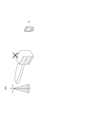
- FIG. 14 shows an example of Proposal 3.
- a RIS and a rectangular target area #3 are shown.
- step 1 the RIS aligns two directions (e.g., dimensions) of the RIS to the horizontal and vertical directions of the target area. Then, based on the principles of geometric optics, the focus #1 of the one-dimensional wide beam is calculated for the horizontal direction, and the focus #2 of the one-dimensional wide beam is calculated for the vertical direction.
- two directions e.g., dimensions
- step 2 the wide-beam codeword is obtained by calculating the Kronecker product of the corresponding one-dimensional RTC codeword, as in equation (15).
- Equation (15) w wide denotes a two-dimensional wide beam codeword, w 1 and w 2 denote one-dimensional RTC codewords in the horizontal and vertical directions, respectively, and equation (15) indicates that w wide is obtained by the Kronecker correlation of w 1 and w 2 .
- the target area can be expanded, reduced, or its shape changed, allowing for flexible control of coverage. This makes it possible to suppress unnecessary radiation outside the target area, avoiding interference outside the target area and reducing power consumption.
- Proposal 3 describes a method of wide beam shaping designed for a rectangular coverage area
- Wide beam shaping may be performed for any shape other than a rectangle.
- the shape of the RIS array is rectangular and the target area is square
- wide beam shaping based on the shape of the target area may be performed in a manner similar to Proposal 3.
- the shape of the RIS array is circular and the target area is elliptical
- wide beam shaping based on the shape of the target area may be performed in a manner similar to Proposal 3.
- Proposal 3 and Proposal 2 may be used in combination. For example, by combining Proposal 2-1 and Proposal 3, a wide beam that covers a rectangular target area may be generated for multiple rectangular target areas. Furthermore, by combining Proposal 2-2 or Proposal 2-3 and Proposal 3, a wide beam that covers a target area that is shaped like a rectangle with part of it missing may be generated.
- the focused beam when a focused beam and a wide beam are generated in a RIS array of the same size, the focused beam can achieve a relatively high SNR, and the wide beam can effectively cover a specific area. Therefore, the focused beam is suitable for transmitting a data channel, and the wide beam is suitable for transmitting a control channel.
- the focused beam may be used to transmit channels other than the data channel (e.g., a control channel, a broadcast channel, etc.), and signals other than signals placed in the data channel may be transmitted.
- the wide beam may be used to transmit channels other than the control channel (e.g., a data channel, a broadcast channel, etc.), and signals other than signals placed in the control channel.
- the SNR gain of the wide beam of RIS array #2 is about 3 dB greater than the SNR gain of RIS array #1.
- the SNR gain of the wide beam increases by about 6 dB.
- the SNR gain of the wide beam in coverage area #2 is about 1.5 dB smaller than the SNR gain in coverage area #1.
- the coverage area becomes four times larger the SNR gain of the wide beam decreases by about 3 dB.
- the size of the coverage area, the size of the RIS array, and the SNR gain of the wide beam show a specific relationship. Therefore, depending on at least one of the size of the coverage area, the size of the RIS array, and the SNR gain of the wide beam, the other two may be set. For example, at least one of the size of the coverage area and the size of the RIS array may be set depending on the desired SNR gain, or the size of the RIS array may be set depending on the desired SNR gain and the size of the desired coverage area.
- Methods based on multi-wide beam generation may be used for beam shaping, utilizing the beamforming gain from each of the RIS elements. Beam shaping based on multi-wide beam generation can provide higher gain in the coverage area compared to methods based on operation mode control and phase mask.
- the technique based on controlling the operating mode and phase masking, is easy to implement.
- the RIS may also transmit capability information (e.g., capability) to the gNB indicating whether or not it supports each proposal and each combination of proposals.
- capability information e.g., capability
- RIS-NCR RIS-NCR
- the RIS switches beams between transmitting control channels and transmitting data channels.
- FIG. 15 illustrates a first example of use case 1.
- a wide beam is generated for the transmission of a control channel.
- a UE-specific narrow beam is generated for the transmission of a data channel.
- the coverage area is appropriately adjusted based on UE feedback.
- the UE may provide feedback to the network (e.g., gNB) via UL signals, and the network may provide the feedback to the RIS.
- the UE may provide feedback directly to the RIS.
- the RIS to which the feedback has been provided may adjust its coverage area based on the feedback.
- the UE may provide feedback to the network, and the gNB may determine information to provide to the RIS (e.g., information on the UE's location, information on the target area, codewords, etc.) to adjust the coverage area based on the feedback, and the gNB may provide the determined information to the RIS.
- the wide beam generated based on the approaches presented in Proposal 1 to Proposal 3 effectively covers the target area and is therefore suitable for transmitting control channels.
- the UE-specific narrow beam generated by the RIS using RTC can increase the SNR gain within the near-field region of the RIS. Therefore, by utilizing the narrow beam for data channel transmission, it is possible to achieve a high data rate for the UE.
- the coverage area is adaptively adjusted, for example by utilizing UE feedback information to reduce the coverage area of the wide beam, which allows for a higher wide beam gain for the transmission of the control channel.
- FIG. 16 is a diagram showing a second example of use case 1.
- FIG. 16 shows an example in which the RIS generates a wide beam for the coverage area in which UE#1 and UE#2 are present.
- the RIS switches between wide beams among multiple patterns of wide beams.
- the UE measures the Reference Signal Received Power (RSRP) and provides feedback.
- RSRP Reference Signal Received Power
- the network dynamically adjusts the coverage range of the wide beam based on the feedback.
- the coverage of the wide beam may be switched from a large size to a small size. Based on the UE's feedback on RSRP measurements, the network determines whether the UE is in the current wide beam coverage and dynamically adjusts the coverage.
- Figure 17 is a diagram showing Alt. 1 of a second example of use case 1.
- coverage patterns of four wide beams of different sizes, Pattern #1 to Pattern #4 are shown.
- the RIS first uses the wide beam of Pattern #1, which is the largest of the four, and UEs #1 and #2 measure the RSRP for Pattern #1. Based on the UE feedback, the RIS switches from the wide beam of Pattern #1 to the wide beam of Pattern #2. Similarly, the RIS switches in turn to the wide beam of Pattern #3 and then to the wide beam of Pattern #4, and as a result, Pattern #3 is selected.
- the coverage area may be divided into multiple sub-regions, and the differently shaped wide beams may be switched to scan one or a combination of the multiple sub-regions, where the network determines the presence or absence of a UE in each sub-region based on feedback received from the UE.
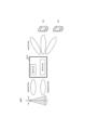
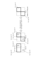
- FIG. 18 is a diagram showing Alt. 2 of a second example of use case 1.
- the coverage area is divided into four sub-areas.
- a pattern #1 including sub-area #1 and sub-area #2 and a pattern #2 including sub-area #1 and sub-area #4 are switched. Note that although two patterns are shown in FIG. 18, a pattern other than these patterns may be switched.
- UE #1 which exists in sub-region #1
- UE #2 which exists in sub-region #4
- measure the RSRP for each of multiple patterns patterns #1 and #2 in FIG. 18.
- pattern 1 the measurement result of UE #1 indicates a high RSRP
- the measurement result of UE #2 indicates a low RSRP.
- pattern #2 the measurement results of UE #1 and UE #2 each indicate a high RSRP. Based on feedback from UEs showing such measurement results, the RIS selects pattern #2.
- the beam is switched between transmitting a control channel and transmitting a data channel.
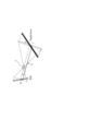
- FIG. 19 is a diagram showing a first example of use case 2.
- a narrow beam generated for transmitting a data channel and a wide beam generated for transmitting a control channel are shown. Note that the example shown in FIG. 19 corresponds to the gNB transmitting a signal via the RIS, rather than the RIS forwarding a signal transmitted from the gNB.
- a wide beam is generated for transmission of a control channel.
- a UE-specific narrow beam is generated for transmission of a data channel.
- an estimation of the SNR gain for the UE-specific narrow beam is achieved by utilizing the measurement of the RSRP for the wide beam.
- the wide beam generated based on the approaches presented in Proposal 1 to Proposal 3 effectively covers the target area and is therefore suitable for transmitting control channels.
- the UE-specific narrow beam generated by the RIS using RTC can increase the SNR gain within the near-field region of the RIS. Therefore, by utilizing the narrow beam for data channel transmission, it is possible to achieve high data rates for the UE.
- step 1 the difference between the average SNR gain in the coverage area and the SNR gain of the UE-specific beam is estimated based on the pattern information of the wide beam.
- step 2 the SNR gain of the data channel is estimated by combining measurement information such as the RSRP of the control channel with the wide beam pattern information.
- steps 1 and 2 described above may be performed by the RIS, or at least one of them may be performed by the RIS and the rest may be performed by the network (e.g., gNB).
- the network e.g., gNB
- Use case 3 describes beam refinement. For example, considering the limited availability of CSI-RS resources, it is impractical to use narrow beams for CSI-RS beam scanning. Instead, a wide beam CSI-RS scanning scheme can be used to effectively utilize the limited CSI-RS resources, thereby improving beam refinement.
- the UE Because the UE knows the patterns associated with each CSI-RS wide beam, it can achieve beam refinement by analyzing measurements such as the RSRP. It can then report the codeword corresponding to the refined beam to the network.
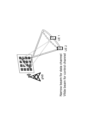
- FIG. 20A is a diagram showing a first example of use case 3.
- FIG. 20B is a diagram showing a second example of use case 3.
- FIG. 20A corresponds to the above-mentioned use case 2 (RIS-aided mega MIMO), and
- FIG. 20B corresponds to an example in which the RIS forwards a signal transmitted from a gNB.
- step 1 of use case 3 the UE performs measurements on the CSI-RS.
- step 2 based on the measurement results, the UE selects a wide beam (hereafter referred to as a CSI-RS wide beam) on which the UE transmits multiple CSI-RS. For example, the UE selects CSI-RS wide beams whose RSRPs are close to each other. Then, the UE identifies the pattern of the target refinement beam as the intersection of the patterns of the selected wide beams.
- the UE reports the codeword corresponding to the refined beam to the network.
- the UE performs measurements on CSI-RS #1 to #3, and selects a wide beam that transmitted CSI-RS #1 and #2 whose RSRPs are close to each other. The UE then identifies the pattern of the target refinement beam as the intersection of the patterns of the wide beams that transmitted CSI-RS #1 and #2. The UE reports the codeword corresponding to the refined beam to the network.
- the RIS can generate a more appropriate wide beam for the UE.
- the following describes the generation of a wide beam by a RIS, the control of the operation mode of the RIS, and the SSB transmission method by the RIS.
- the SSB transmission method by the RIS may be, for example, a method using a wide beam.
- RIS wide beam generation includes coverage area measurement and feedback, beam type indication, and code word indication.
- Controlling the operation mode of the RIS includes matters such as instructing the operation mode.
- the RIS SSB forwarding method includes an instruction for SSB power control.
- the instruction for SSB power control may be, for example, an instruction from the gNB to the RIS.
- the network may determine the coverage area and report geometric information based on UE measurements, where the information measured and reported by the UE may be at least one of the following: RSRP/RSRQ (Reference Signal Received Quality)/RSSI (Received Signal Strength Indicator)/Rx-Tx Time Difference/RTT (Round Trip Time).
- RSRP/RSRQ Reference Signal Received Quality
- RSSI Receiveived Signal Strength Indicator
- Rx-Tx Time Difference/RTT Red Trip Time
- the information reported by the UE may include location information of the UE determined by GPS (Global Positioning System) or the like, and information regarding the relative position between the US and the gNB (or RIS) estimated by the signal received by the UE.
- GPS Global Positioning System
- the signal that the UE measures may be an existing signal, or it may be a signal that is different from the existing signal and indicates the codeword required to generate a wide beam.
- the beam for the data channel may be a narrow beam (or a focused beam), and the beam for the control channel may be a wide beam.
- Beam types are not limited to these.
- a wide beam may be used as a broadcast beam.
- a beam may be selected depending on the type, number, and use of signals included in the channel.
- F may be provided to the RIS using one of the following two options:
- Option 1 “F” is provided directly by the network (e.g., gNB).
- Option 2 The network provides parameters such as D, d, L, ⁇ , and ⁇ shown in Proposal 1.
- the RIS calculates F based on D, d, L, ⁇ , and ⁇ and either Equation (12) or Equation (13) in Proposal 1.
- the parameter values may be provided directly, quantized information on the parameter values may be provided, the parameter values may be converted by a specific calculation and provided, or an index or the like associated with the parameter values may be provided.
- ⁇ RIS wide beam generation> ⁇ Shaping of wide beams: Generation of multi-wide beams in Proposal 2>
- the indication of multiple code words for multi-wide beams may be the same as the indication of code words shown in the first example and/or the second example of the related art.
- "D_2" indicating the distance between the RIS and the UE is replaced with "F” indicating the focal length.
- multiple codewords may be dictated by the network, and the power allocation factor of each codeword may be dictated by the network.
- the RIS may calculate the multi-beam codeword based on equation (14) of Proposal 2.
- the operating mode is instructed for each element in the RIS array or for each group of elements in the RIS array.
- a control signal (or control signaling) instructed from the network to the RIS may include N operating mode instructions for N elements (N is an integer equal to or greater than 1) or a group of elements. Note that there do not have to be N operating mode instructions for N elements or a group of N elements. For example, if N elements are distinguished into K ways (K is an integer equal to or greater than 1 and less than N), there may be K operating mode instructions. Note that a group of elements may include one or more elements.
- one operating mode is specified for a set of elements in the RIS array or a set of groups of elements in the RIS array.
- the set of elements includes zero or more elements.
- the set of groups of elements includes zero or more groups.
- a control signal (or control signaling) specified from the network to the RIS includes an instruction for one operating mode.
- the control signaling specifies a set of elements or a set of groups of elements that corresponds to the specified operating mode.
- an instruction for a first operating mode may correspond to an instruction for a first set of elements or a set of groups of first elements
- an instruction for a second operating mode may correspond to an instruction for a second set of elements or a set of groups of second elements.
- a set of elements or a set of element groups in a RIS array is specified, and a default operating mode is applied to the specified set of elements or set of element groups.
- the number of bits required to indicate the above-mentioned operation modes may depend on the total number of operation modes supported by the capabilities (e.g., capabilities) of the RIS and/or the total number of operation modes pre-configured by the network.
- the number of bits required to indicate the above-mentioned operation modes may vary depending on the total number of operation modes supported by the capabilities (e.g., capabilities) of the RIS and/or the total number of operation modes pre-configured by the network.
- Proposal 2 phase mask> A set of elements or a set of element groups in the RIS array is pointed to by the network, and the RIS applies a random phase to the pointed to set of elements or set of element groups.
- the codeword instruction of Proposal 3 may be the same as the codeword instruction shown in the first and/or second examples of the related art.
- “D_2” indicating the distance between the RIS and the UE is replaced with the focal length.
- RIS operation mode The RIS is deployed to operate in various modes including reflection mode, refraction mode, scattering mode, absorption mode, modulation mode, etc. And, the operation mode of all or specific elements of the RIS needs to be controlled to achieve various objectives such as interference removal, beam shaping, performance enhancement in specific areas (e.g., Intelligent Omni-Surfaces (IOS) etc.).
- IOS Intelligent Omni-Surfaces
- the idle state corresponds to, for example, a scattering mode and/or an absorptive mode
- the operating state corresponds to, for example, a reflective mode, a refractive mode and/or a modulating mode.
- the energy absorbed by the system may be used to power the RIS-MT to avoid potential interference from the RIS.
- a specific signal is defined. Upon detection of the specific signal from the network, the RIS switches from an idle state to an active state. Alternatively, upon detection of the specific signal from the network, the RIS switches from an active state to an idle state.
- the idle instruction or operating mode instruction applies for one or more subsequent time units until a new idle instruction or operating mode instruction is received.
- Option 3 indicates idle or operational state in time units.
- option 4 similar to NCR, if a valid beam or codebook is indicated for the time unit, it is in operational mode, otherwise it is in idle mode.
- This mode may be, for example, Intelligent Omni-Surfaces (IOS).
- IOS Intelligent Omni-Surfaces
- the reflected and refracted power distribution may be commanded by the network.
- this command one of two options may be applied.
- option 1 the power distribution command is applied for the following time units until a new command is received.
- option 2 the power allocation command is given on a time basis.
- Multi-beam instructions For example, it is envisioned that communication and position estimation (eg, positioning) occur simultaneously.
- both the number of beams and the power allocation between the beams are dynamically adjusted based on actual needs.
- communication and position estimation e.g., positioning
- a case in which communication and position estimation are performed simultaneously and a case in which one of communication and position estimation is performed may be switched.
- the RIS for example, modulates the incident signal.
- the RIS may be used to modulate the signal of the incident wave.
- the signal may be modulated and various functions may be possible, such as shaping the signal and encoding information into the incident wave.
- the network may instruct whether the RIS modulates the signal. For this instruction, at least one of two options may be applied. In option 1, the instruction whether the RIS modulates the signal applies to subsequent time units until a new instruction is received. In option 2, the instruction whether the RIS modulates the signal is given in time units.
- RIS SSB transfer method In existing methods, the RIS uses multiple narrow beams to relay the SSB transmitted by the gNB, but these methods typically involve significant allocation of SSB resources or require significant modifications to the SSB method.
- the RIS utilizes a wide beam to transmit SSB resources transmitted by the gNB to the UE.
- the power of the SSB beam transmitted from the base station to the RIS may be adjusted differently than the power of other SSB beams.
- the transmit power of the SSB is given by higher layer parameters (e.g., ss-PBCH-BlockPower).
- the EPRE of the CSI-RS is derived based on ss-PBCH-BlockPower and an offset to the Tx power of the SSB provided by the higher layer parameters.
- the derivation method must be extended if the powers of different SSBs are different from each other.
- the downlink transmission power of the SSBs is then given by a higher layer parameter per SSB or per group of SSBs. At least one of two variations on the provision of this parameter may be applied.
- Variation 1 The EPRE (Energy Per Resource Element) of the first SSB group (e.g. SSBs transmitted directly to the UE) is provided using existing parameters.
- the EPRE of other SSB groups (e.g. SSBs transmitted to the RIS) other than the first SSB group is provided by new parameters.
- the first SSB group here may be the SSB group that is first in the transmission order.
- Variation 2 The EPRE of the first SSB group (e.g. SSBs transmitted directly to the UE) is provided directly using existing parameters.
- the EPRE of other SSB groups other than the first SSB group e.g. SSBs transmitted to the RIS
- the EPRE of the CSI-RS is derived from the power offset given by higher layer parameters and the downlink transmit power of the SSB (SSB DL Tx power).
- the derivation method has to be extended if the powers of different SSBs are different from each other. For example, any of the following three options may be applied as the derivation method:
- Option 1 For CSI-RS, it is dictated by higher layer parameters.
- the EPRE of CSI-RS is derived from the DL transmit power of one of the SSBs.
- Option 2 For CSI-RS EPRE, by default, the DL transmit power of the first SSB or first SSB group is derived from the SSB transmit power provided by existing parameters (e.g., legacy parameters).
- Option 3 For CSI-RS, if QCL is performed on SSB, the EPRE of the CSI-RS is derived from the DL transmit power of the SSB used as the QCL reference RS.
- CSI-RS EPRE and/or CSI-RS power offset for SSB may be provided per CSI-RS or per CSI-RS group.
- the UE needs to support the RTC codebook.
- the RTC codeword for each SSB or CSI-RS resource is indicated to the UE.
- the codeword indication in this case may be similar to the codeword indication in the first and/or second examples of the related technology.
- the UE may be set with "N_1", “N_2", “O_1”, and “O_2” as shown in the first and/or second examples of the related technology (for example, the above-mentioned item “Parameters related to the codebook/precoder").
- the UE may also be indicated with codeword indexes "k_1” and "k_2" for each SSB or CSI-RS resource.
- the UE may also be indicated with "D_2", which indicates the distance between the RIS and the UE, as in the first and/or second examples of the related technology.
- the UE may be indicated with the focal distance F from the RIS to the focal position in the above-mentioned proposal for each SSB or CSI-RS resource.
- the UE reports the RTC codeword of the refined beam identified by the UE. This reporting may use one of the following two options:
- the report includes the indices k_1 and k_2 of the codewords of the refined beams identified by the UE.
- the report includes the index k_1 of the codeword of the refined beam identified by the UE, and k_1. Additionally, the report includes the index of the SSB or CSI-RS and the L1-RSRP/SINR of the SSB or CSI-RS.
- a RIS forwards a signal transmitted by a gNB to a UE has been shown, but the present disclosure is not limited to this.
- the present disclosure may be applied to uplink processing in which a RIS forwards a signal transmitted by a UE to a gNB, or may be applied to processing in which a RIS forwards a signal transmitted by a UE to a UE other than the UE.
- a configuration may be adopted in which a first RIS forwards a signal transmitted by the gNB to a second RIS, and the second RIS forwards the signal to the UE.
- the first RIS may generate multiple beams (for example, the multi-wide beam described above) and forward the signal to multiple second RISs, and each of the multiple second RISs may further forward the signal to the UE.
- A/B and “at least one of A and B” may be interpreted as interchangeable.
- A/B/C may mean “at least one of A, B, and C.”
- Radio Resource Control RRC
- RRC parameters RRC parameters
- RRC messages higher layer parameters, fields, information elements (IEs), settings, etc.
- IEs information elements
- CE Medium Access Control
- update commands activation/deactivation commands, etc.
- the higher layer signaling may be, for example, any one of Radio Resource Control (RRC) signaling, Medium Access Control (MAC) signaling, broadcast information, other messages (e.g., messages from the core network, such as positioning protocols (e.g., NR Positioning Protocol A (NRPPa)/LTE Positioning Protocol (LPP)) messages), or a combination thereof.
- RRC Radio Resource Control
- MAC Medium Access Control
- LPP LTE Positioning Protocol
- MAC signaling may use, for example, a MAC Control Element (MAC CE), a MAC Protocol Data Unit (PDU), etc.
- Broadcast information may be, for example, a Master Information Block (MIB), a System Information Block (SIB), Remaining Minimum System Information (RMSI), Other System Information (OSI), etc.
- MIB Master Information Block
- SIB System Information Block
- RMSI Remaining Minimum System Information
- OSI Other System Information
- the physical layer signaling may be, for example, Downlink Control Information (DCI), Uplink Control Information (UCI), etc.
- DCI Downlink Control Information
- UCI Uplink Control Information
- aperture, antenna array, array, subarray (multiple antenna elements, part of an array), panel, RIS, RIS array, scattering element array, etc. may be interchangeable.
- antenna, antenna element, scattering element, etc. may be interchangeable.
- NCR NCR, RIS, NCR containing RIS, network node, device, IAB, IAB-MT (Mobile Termination), IAB-DU (Distribution Unit), IAB-CU (Central Unit), terminal, base station, relay station, relay device, repeater, reflector, transmittance plate, RIS-NCR, RIS type NCR, extended NCR, etc.
- IAB IAB-MT
- IAB-DU Distribution Unit
- IAB-CU Central Unit
- terminal base station, relay station, relay device, repeater, reflector, transmittance plate
- RIS-NCR RIS type NCR, extended NCR, etc.
- Fig. 21 is a block diagram showing an example of a configuration of a base station 100 according to an embodiment of the present disclosure.
- the base station 100 includes, for example, a transmitting unit 101, a receiving unit 102, and a control unit 103.
- the base station 100 communicates with a terminal 200 (see Fig. 22) wirelessly.
- the transmitting unit 101 and the receiving unit 102 may be collectively referred to as a communication unit.
- the control unit may be referred to as a processing unit, a processor, or the like.
- the transmitting unit 101 transmits a DL signal to the terminal 200.
- the transmitting unit 101 transmits the DL signal under the control of the control unit 103.
- the DL signal may include information indicating scheduling regarding the signal transmission of the terminal 200 (for example, an UL grant), control information of higher layers, etc.
- the transmitting unit 101 transmits various control signals (such as control signals for higher layers), reference signals, data signals, etc., as DL signals to the terminal 200 and/or the wireless device 300.
- the transmitting unit 101 transmits various signals, channels, setting information, control information, etc., described in the above embodiments, as DL signals to the terminal 200.
- the transmitting unit 101 transmits information related to the control of the terminal 200, generated by the control unit 103, to the terminal 200. Also, for example, the transmitting unit 101 transmits information related to the control of the wireless device 300, generated by the control unit 103, to the wireless device 300. Also, the transmitting unit 101 transmits a data signal generated by the control unit 103 to the terminal 200.
- the receiving unit 102 receives the UL signal transmitted from the terminal 200.
- the receiving unit 102 receives the UL signal under the control of the control unit 103.
- the receiving unit 102 may also receive the UL signal transmitted from the wireless device 300.
- the receiving unit 102 receives, as UL signals, signals including terminal capability information (e.g., UE capability) of the terminal 200, various control signals, reference signals, data signals, etc. from the terminal 200.
- the receiving unit 102 may also receive signals including capability information (e.g., capability) of the wireless device 300.
- the control unit 103 controls the overall (communication) operation of the base station 100, including the transmission processing in the transmission unit 101 and the reception processing in the reception unit 102.
- control unit 103 acquires information such as data and control information from the upper layer and outputs it to the transmission unit 101.
- the control unit 103 also outputs data and control information received from the reception unit 102 to the upper layer.
- control unit 103 allocates resources to be used for transmitting and receiving DL signals and/or resources to be used for transmitting and receiving UL signals based on a signal (e.g., data and control information, etc.) received from the terminal 200 and/or data and control information, etc. acquired from a higher layer. Information regarding the allocated resources may be included in the control information transmitted to the terminal 200.
- a signal e.g., data and control information, etc.
- Information regarding the allocated resources may be included in the control information transmitted to the terminal 200.
- the control unit 103 performs operations other than the transmission and reception described in the above embodiment (note that these operations may be performed by the transmission unit 101 and/or the reception unit 102).
- the control unit 103 may also generate control information related to the forwarding operation of the wireless device 300.
- the control unit 103 may transmit instructions (e.g., control information) related to communication control of the wireless device 300 via the transmission unit 101.
- FIG. 22 is a block diagram showing an example of the configuration of a terminal 200 according to an embodiment of the present disclosure.
- the terminal 200 includes, for example, a receiving unit 201, a transmitting unit 202, and a control unit 203.
- the terminal 200 communicates with, for example, a base station 100 (see FIG. 21) wirelessly.
- the receiving unit 201 and the transmitting unit 202 may be collectively referred to as a communication unit.
- the receiving unit 201 receives a DL signal transmitted from the base station 100.
- the receiving unit 201 receives the DL signal under the control of the control unit 203.
- the receiving unit 201 receives various control signals, reference signals, data signals, etc., as DL signals from the base station 100.
- the receiving unit 201 receives various signals, channels, setting information, control information, etc., described in the above embodiments, as DL signals from the base station 100.
- the receiving unit 201 receives a signal from the base station 100.
- the transmitting unit 202 transmits the UL signal to the base station 100.
- the transmitting unit 202 transmits the UL signal under the control of the control unit 203.
- the transmitter 202 transmits, as UL signals, signals including information about the processing capabilities of the terminal 200, various control signals, reference signals, data signals, etc. to the base station 100.
- the control unit 203 controls the overall (communication) operation of the terminal 200, including the reception processing in the receiving unit 201 and the transmission processing in the transmitting unit 202.
- control unit 203 acquires information such as data and control information from a higher layer and outputs it to the transmission unit 202.
- the control unit 203 also outputs, for example, data and control information received from the reception unit 201 to the higher layer.
- the control unit 203 performs operations other than the transmission and reception described in the above embodiment (note that these operations may be performed by the receiving unit 201 and/or the transmitting unit 202).
- the signal that the terminal 200 receives from the base station 100 may be a signal transmitted directly from the base station 100, or may be a signal transmitted from the base station 100 and forwarded by the wireless device 300.
- the signal that the terminal 200 transmits to the base station 100 may be received directly by the base station 100, or may be forwarded by the wireless device 300 and received by the base station 100. In this case, the terminal 200 does not need to recognize whether the signal was forwarded by the wireless device 300 or not.
- FIG. 23 is a block diagram showing an example of the configuration of a wireless device 300 according to an embodiment of the present disclosure.
- the wireless device 300 corresponds to an example of a RIS.
- the wireless device 300 includes, for example, a receiving unit 301, a transmitting unit 302, and a control unit 303.
- the wireless relay device 300 communicates wirelessly with, for example, a base station 100 (see FIG. 21) and a terminal 200 (see FIG. 22).
- the receiving unit 301 and the transmitting unit 302 may be collectively referred to as a communication unit.
- the communication unit has a radiation surface (for example, a RIS array) that emits radio waves, and may transmit a signal from the radiation surface or receive a signal at the radiation surface.
- a radiation surface for example, a RIS array
- the receiving unit 301 receives a DL signal transmitted from the base station 100.
- the receiving unit 301 also receives a UL signal transmitted from the terminal 200.
- the receiving unit 301 receives DL signals and UL signals under the control of the control unit 303.
- the received signals may include signals addressed to the base station 100, signals addressed to the terminal 200, and signals addressed to the wireless device 300.
- the receiving unit 301 receives a signal (e.g., a signal unique to the terminal 200) transmitted from the base station 100 to the terminal 200.
- the forwarding process may include at least one of a process of transmitting a signal addressed to the terminal 200 received from the base station 100 to the terminal 200 and a process of receiving a signal addressed to the base station 100 from the terminal 200.
- the transmitting unit 302 transmits to the base station 100 a UL signal addressed to the base station 100 that is received from the terminal 200.
- the transmitting unit 302 also transmits to the terminal 200 a DL signal addressed to the terminal 200 that is received from the base station 100.
- the transmitting unit 302 transmits a UL signal under the control of the control unit 303.
- the transmitting unit 302 transfers a signal addressed to the terminal 200 that is received from the base station 100 to the terminal 200.
- the control unit 303 controls the overall (communication) operation of the wireless device 300, including the reception processing in the receiving unit 301 and the transmission processing in the transmitting unit 302.
- control unit 303 For example, the control unit 303 generates a beam to be used by the transmission unit 302.
- the control unit 303 uses the acquired information about the target area (the area covered by the wireless device 300) to select (determine) a code word based on the geometric relationship between the wireless device 300 and the target area (for example, the focal position or focal length).
- the control unit 303 then applies the determined code word to control the generation of the beam.
- the control unit 303 performs operations other than the transmission and reception described in the above embodiment (note that these operations may be performed by the receiving unit 301 and/or the transmitting unit 302).
- the wireless device 300 in this disclosure may be an example of a communication device.
- the wireless device 300 in this disclosure may also be called by other names such as a forwarding device or a relay device.
- the wireless device 300 in this disclosure may also be replaced with a terminal 200 (e.g., UE).
- the wireless device 300 may be considered as a terminal 200 having a forwarding function (or relay function).
- the above-mentioned wireless device (e.g., RIS) 300 includes a control unit 303 that determines a code word based on the geometric relationship between the wireless device 300 and the area covered by the wireless device 300 and applies the code word to generate a beam that covers the area, and a communication unit that outputs a signal using the beam.
- a control unit 303 that determines a code word based on the geometric relationship between the wireless device 300 and the area covered by the wireless device 300 and applies the code word to generate a beam that covers the area
- a communication unit that outputs a signal using the beam.
- control unit 303 determines the focal position based on the geometric relationship between the radiation surface of the communication unit (transmitter 302 and/or receiver 301) and the area, and determines the code word that is focused on the focal position.
- the control unit 303 determines the focal position based on the geometric relationship between each of the multiple areas and the radiation surface, determines an area code word that is in focus at the focal position corresponding to each of the multiple areas, and determines the code word by performing specific calculation processing on the area code word corresponding to each of the multiple areas.
- the communication unit has multiple antenna elements arranged on a plane, and the control unit 303 switches the setting of at least one of the antenna elements depending on the mode in which the wireless device 300 operates.
- control unit 303 determines the code word based on the shape of the area.
- each functional block may be realized using one device that is physically or logically coupled, or may be realized using two or more devices that are physically or logically separated and directly or indirectly connected (for example, using wires, wirelessly, etc.).
- the functional blocks may be realized by combining the one device or the multiple devices with software.
- Functions include, but are not limited to, judgement, determination, judgment, calculation, computation, processing, derivation, investigation, search, confirmation, reception, transmission, output, access, resolution, selection, election, establishment, comparison, assumption, expectation, regard, broadcasting, notifying, communicating, forwarding, configuring, reconfiguring, allocating, mapping, and assignment.
- a functional block (component) that performs the transmission function is called a transmitting unit or transmitter.
- a base station, a terminal, a wireless device, etc. in one embodiment of the present disclosure may function as a computer that performs processing of the wireless communication method of the present disclosure.
- FIG. 24 is a diagram showing an example of the hardware configuration of a base station, a terminal, and a wireless device in one embodiment of the present disclosure.
- the above-mentioned base station 100, terminal 200, and wireless device 300 may be physically configured as a computer device including a processor 1001, a memory 1002, a storage 1003, a communication device 1004, an input device 1005, an output device 1006, a bus 1007, etc.
- the term "apparatus” can be interpreted as a circuit, device, unit, etc.
- the hardware configurations of the base station 100, the terminal 200, and the wireless device 300 may be configured to include one or more of the devices shown in the figures, or may be configured to exclude some of the devices.
- the functions of the base station 100, the terminal 200, and the wireless device 300 are realized by loading specific software (programs) onto hardware such as the processor 1001 and memory 1002, causing the processor 1001 to perform calculations, control communications by the communication device 1004, and control at least one of the reading and writing of data in the memory 1002 and the storage 1003.
- the processor 1001 for example, operates an operating system to control the entire computer.
- the processor 1001 may be configured as a central processing unit (CPU) including an interface with peripheral devices, a control device, an arithmetic unit, registers, etc.
- CPU central processing unit
- control unit 103, control unit 203, and control unit 303, etc. may be realized by the processor 1001.
- the processor 1001 also reads out programs (program codes), software modules, data, etc. from at least one of the storage 1003 and the communication device 1004 into the memory 1002, and executes various processes according to these.
- the programs used are those that cause a computer to execute at least some of the operations described in the above-mentioned embodiments.
- the control unit 203 of the terminal 200 may be implemented by a control program stored in the memory 1002 and running on the processor 1001, and similar implementations may be made for other functional blocks.
- the above-mentioned various processes have been described as being executed by one processor 1001, they may be executed simultaneously or sequentially by two or more processors 1001.
- the processor 1001 may be implemented by one or more chips.
- the programs may be transmitted from a network via a telecommunications line.
- Memory 1002 is a computer-readable recording medium and may be composed of at least one of, for example, ROM (Read Only Memory), EPROM (Erasable Programmable ROM), EEPROM (Electrically Erasable Programmable ROM), RAM (Random Access Memory), etc. Memory 1002 may also be called a register, cache, main memory, etc. Memory 1002 can store executable programs (program codes), software modules, etc. for implementing a wireless communication method relating to one embodiment of the present disclosure.
- ROM Read Only Memory
- EPROM Erasable Programmable ROM
- EEPROM Electrical Erasable Programmable ROM
- RAM Random Access Memory
- Memory 1002 may also be called a register, cache, main memory, etc.
- Memory 1002 can store executable programs (program codes), software modules, etc. for implementing a wireless communication method relating to one embodiment of the present disclosure.
- Storage 1003 is a computer-readable recording medium, and may be, for example, at least one of an optical disk such as a CD-ROM (Compact Disc ROM), a hard disk drive, a flexible disk, a magneto-optical disk (e.g., a compact disk, a digital versatile disk, a Blu-ray (registered trademark) disk), a smart card, a flash memory (e.g., a card, a stick, a key drive), a floppy (registered trademark) disk, a magnetic strip, etc.
- Storage 1003 may also be referred to as an auxiliary storage device.
- the above-mentioned storage medium may be, for example, a database, a server, or other suitable medium including at least one of memory 1002 and storage 1003.
- the communication device 1004 is hardware (transmitting/receiving device) for communicating between computers via at least one of a wired network and a wireless network, and is also referred to as, for example, a network device, a network controller, a network card, or a communication module.
- the communication device 1004 may be configured to include a high-frequency switch, a duplexer, a filter, a frequency synthesizer, etc., to realize, for example, at least one of Frequency Division Duplex (FDD) and Time Division Duplex (TDD).
- FDD Frequency Division Duplex
- TDD Time Division Duplex
- the above-mentioned transmitting unit 101, receiving unit 102, receiving unit 201, transmitting unit 202, receiving unit 301, and transmitting unit 302 may be realized by the communication device 1004.
- the input device 1005 is an input device (e.g., a keyboard, a mouse, a microphone, a switch, a button, a sensor, etc.) that accepts input from the outside.
- the output device 1006 is an output device (e.g., a display, a speaker, an LED lamp, etc.) that performs output to the outside. Note that the input device 1005 and the output device 1006 may be integrated into one structure (e.g., a touch panel).
- each device such as the processor 1001 and memory 1002 is connected by a bus 1007 for communicating information.
- the bus 1007 may be configured using a single bus, or may be configured using different buses between each device.
- the base station 100, the terminal 200, and the wireless device 300 may be configured to include hardware such as a microprocessor, a digital signal processor (DSP), an application specific integrated circuit (ASIC), a programmable logic device (PLD), or a field programmable gate array (FPGA), and some or all of the functional blocks may be realized by the hardware.
- the processor 1001 may be implemented using at least one of these pieces of hardware.
- the notification of information is not limited to the embodiment described in the present disclosure, and may be performed using other methods.
- the notification of information may be performed by physical layer signaling (e.g., Downlink Control Information (DCI), Uplink Control Information (UCI)), higher layer signaling (e.g., Radio Resource Control (RRC) signaling, Medium Access Control (MAC) signaling, broadcast information (Master Information Block (MIB), System Information Block (SIB)), other signals, or combinations thereof.
- the RRC signaling may be called an RRC message, and may be, for example, an RRC Connection Setup message, an RRC Connection Reconfiguration message, or the like.
- LTE Long Term Evolution
- LTE-A LTE-Advanced
- SUPER 3G IMT-Advanced
- 4th generation mobile communication system 4th generation mobile communication system
- 5th generation mobile communication system 5G
- 6th generation mobile communication system 6th generation mobile communication system
- xth generation mobile communication system xG (x is, for example, an integer or a decimal)
- Future Radio Access FAA
- new Radio NR
- New radio access NX
- Future generation radio access Future generation radio access
- W-CDMA registered trademark
- GSM registered trademark
- UMB Ultra Mobile Broadband
- IEEE 802.11 Wi-Fi (registered trademark)
- IEEE 802.16 WiMAX (registered trademark)
- IEEE 802.17 WiMAX (registered trademark)
- IEEE 802.19 WiMAX (registered trademark)
- IEEE 802.20 WiMAX (registered trademark)
- IEEE 802.21 WiMAX (registered trademark)
- a specific operation performed by a base station may be performed by its upper node in some cases.
- various operations performed for communication with a terminal may be performed by at least one of the base station and other network nodes other than the base station (e.g., MME or S-GW, etc., but are not limited to these).
- MME Mobility Management Entity
- S-GW Serving Mobility Management Entity
- the above example illustrates a case where there is one other network node other than the base station, it may be a combination of multiple other network nodes (e.g., MME and S-GW).
- Information, etc. may be output from a higher layer (or a lower layer) to a lower layer (or a higher layer).
- Information may be input/output via multiple network nodes.
- the input and output information may be stored in a specific location (e.g., memory) or may be managed using a management table.
- the input and output information may be overwritten, updated, or added.
- the output information may be deleted.
- the input information may be transmitted to another device.
- the determination may be based on a value represented by one bit (0 or 1), a Boolean value (true or false), or a numerical comparison (e.g., comparison with a predetermined value).
- notification of predetermined information is not limited to being done explicitly, but may be done implicitly (e.g., not notifying the predetermined information).
- Software shall be construed broadly to mean instructions, instruction sets, code, code segments, program code, programs, subprograms, software modules, applications, software applications, software packages, routines, subroutines, objects, executable files, threads of execution, procedures, functions, etc., whether referred to as software, firmware, middleware, microcode, hardware description language, or otherwise.
- software, instructions, information, etc. may be transmitted and received via a transmission medium.
- a transmission medium such as coaxial cable, fiber optic cable, twisted pair, Digital Subscriber Line (DSL)), and/or wireless technologies (such as infrared, microwave), then at least one of these wired and wireless technologies is included within the definition of a transmission medium.
- wired technologies such as coaxial cable, fiber optic cable, twisted pair, Digital Subscriber Line (DSL)
- wireless technologies such as infrared, microwave
- the information, signals, etc. described in this disclosure may be represented using any of a variety of different technologies.
- the data, instructions, commands, information, signals, bits, symbols, chips, etc. that may be referred to throughout the above description may be represented by voltages, currents, electromagnetic waves, magnetic fields or magnetic particles, optical fields or photons, or any combination thereof.
- At least one of the channel and the symbol may be a signal (signaling).
- the signal may be a message.
- a component carrier (CC) may be called a carrier frequency, a cell, a frequency carrier, etc.
- the information, parameters, etc. described in the present disclosure may be represented using absolute values, may be represented using relative values from a predetermined value, or may be represented using other corresponding information.
- a radio resource may be indicated by an index.
- the names used for the parameters described above are not intended to be limiting in any way. Furthermore, the formulas etc. using these parameters may differ from those explicitly disclosed in this disclosure.
- the various channels (e.g., PUCCH, PDCCH, etc.) and information elements may be identified by any suitable names, and therefore the various names assigned to these various channels and information elements are not intended to be limiting in any way.
- Base station BS
- radio base station fixed station
- NodeB NodeB
- eNodeB eNodeB
- gNodeB gNodeB
- a base station may also be referred to by terms such as a macro cell, a small cell, a femto cell, a pico cell, etc.
- a base station can accommodate one or more (e.g., three) cells.
- a base station accommodates multiple cells, the entire coverage area of the base station can be divided into multiple smaller areas, and each smaller area can also provide communication services by a base station subsystem (e.g., a small indoor base station (RRH: Remote Radio Head).
- RRH Remote Radio Head
- the term "cell” or “sector” refers to a part or the entire coverage area of at least one of the base station and base station subsystems that provide communication services in this coverage.
- MS Mobile Station
- UE User Equipment
- a mobile station may also be referred to by those skilled in the art as a subscriber station, mobile unit, subscriber unit, wireless unit, remote unit, mobile device, wireless device, wireless communication device, remote device, mobile subscriber station, access terminal, mobile terminal, wireless terminal, remote terminal, handset, user agent, mobile client, client, or some other suitable terminology.
- At least one of the base station and the mobile station may be called a transmitting device, a receiving device, a communication device, etc.
- At least one of the base station and the mobile station may be a device mounted on a moving object, the moving object itself, etc.
- the moving object refers to an object that can move, and the moving speed is arbitrary. It also naturally includes the case where the moving object is stopped.
- the moving object includes, but is not limited to, for example, a vehicle, a transport vehicle, an automobile, a motorcycle, a bicycle, a connected car, an excavator, a bulldozer, a wheel loader, a dump truck, a forklift, a train, a bus, a handcar, a rickshaw, a ship and other watercraft, an airplane, a rocket, an artificial satellite, a drone (registered trademark), a multicopter, a quadcopter, a balloon, and objects mounted thereon.
- the moving object may also be a moving object that runs autonomously based on an operation command.
- At least one of the base station and the mobile station may be a device that does not necessarily move during communication operations.
- at least one of the base station and the mobile station may be an IoT (Internet of Things) device such as a sensor.
- IoT Internet of Things
- the base station in the present disclosure may be read as a terminal.
- the embodiment of the present disclosure may be applied to a configuration in which communication between a base station and a terminal is replaced with communication between multiple terminals (which may be called, for example, D2D (Device-to-Device) or V2X (Vehicle-to-Everything)).
- the terminal 200 and the wireless device 300 may be configured to have the functions of the base station 100 described above.
- terms such as "uplink” and “downlink” may be read as terms corresponding to communication between terminals (for example, "side”).
- the uplink channel, the downlink channel, etc. may be read as a side channel.
- the terminal in this disclosure may be interpreted as a base station.
- the base station 100 and relay station 300 may be configured to have the functions of the terminal 20 described above.
- FIG. 25 shows an example configuration of a vehicle 2001.
- the vehicle 2001 includes a drive unit 2002, a steering unit 2003, an accelerator pedal 2004, a brake pedal 2005, a shift lever 2006, front wheels 2007, rear wheels 2008, an axle 2009, an electronic control unit 2010, various sensors 2021-2029, an information service unit 2012, and a communication module 2013.
- a communication device mounted on the vehicle 2001 and may be applied to the communication module 2013, for example.
- the drive unit 2002 is composed of, for example, an engine, a motor, or a hybrid of an engine and a motor.
- the steering unit 2003 includes at least a steering wheel (also called a handlebar), and is configured to steer at least one of the front wheels and the rear wheels based on the operation of the steering wheel operated by the user.
- the electronic control unit 2010 is composed of a microprocessor 2031, memory (ROM, RAM) 2032, and a communication port (IO port) 2033. Signals are input to the electronic control unit 2010 from various sensors 2021 to 2029 provided in the vehicle 2001.
- the electronic control unit 2010 may also be called an ECU (Electronic Control Unit).
- Signals from the various sensors 2021-2029 include a current signal from a current sensor 2021 that senses the motor current, a front and rear wheel rotation speed signal obtained by a rotation speed sensor 2022, a front and rear wheel air pressure signal obtained by an air pressure sensor 2023, a vehicle speed signal obtained by a vehicle speed sensor 2024, an acceleration signal obtained by an acceleration sensor 2025, an accelerator pedal depression amount signal obtained by an accelerator pedal sensor 2029, a brake pedal depression amount signal obtained by a brake pedal sensor 2026, a shift lever operation signal obtained by a shift lever sensor 2027, and a detection signal for detecting obstacles, vehicles, pedestrians, etc. obtained by an object detection sensor 2028.
- the information service unit 2012 is composed of various devices, such as a car navigation system, an audio system, speakers, a television, and a radio, for providing (outputting) various information such as driving information, traffic information, and entertainment information, and one or more ECUs for controlling these devices.
- the information service unit 2012 uses information acquired from external devices via the communication module 2013, etc., to provide various multimedia information and multimedia services to the occupants of the vehicle 2001.
- the information service unit 2012 may include input devices (e.g., a keyboard, a mouse, a microphone, a switch, a button, a sensor, a touch panel, etc.) that accept input from the outside, and may also include output devices (e.g., a display, a speaker, an LED lamp, a touch panel, etc.) that perform output to the outside.
- input devices e.g., a keyboard, a mouse, a microphone, a switch, a button, a sensor, a touch panel, etc.
- output devices e.g., a display, a speaker, an LED lamp, a touch panel, etc.
- the driving assistance system unit 2030 is composed of various devices that provide functions for preventing accidents and reducing the driving burden on the driver, such as a millimeter wave radar, LiDAR (Light Detection and Ranging), a camera, a positioning locator (e.g., GNSS, etc.), map information (e.g., high definition (HD) maps, autonomous vehicle (AV) maps, etc.), a gyro system (e.g., IMU (Inertial Measurement Unit), INS (Inertial Navigation System), etc.), AI (Artificial Intelligence) chip, and an AI processor, as well as one or more ECUs that control these devices.
- the driving assistance system unit 2030 transmits and receives various information via the communication module 2013 to realize driving assistance functions or autonomous driving functions.
- the communication module 2013 can communicate with the microprocessor 2031 and components of the vehicle 2001 via the communication port.
- the communication module 2013 transmits and receives data via the communication port 2033 between the drive unit 2002, steering unit 2003, accelerator pedal 2004, brake pedal 2005, shift lever 2006, front wheels 2007, rear wheels 2008, axle 2009, microprocessor 2031 and memory (ROM, RAM) 2032 in the electronic control unit 2010, and sensors 2021 to 29, which are provided on the vehicle 2001.
- the communication module 2013 is a communication device that can be controlled by the microprocessor 2031 of the electronic control unit 2010 and can communicate with an external device. For example, it transmits and receives various information to and from the external device via wireless communication.
- the communication module 2013 may be located either inside or outside the electronic control unit 2010.
- the external device may be, for example, a base station, a mobile station, etc.
- the communication module 2013 may transmit at least one of the signals from the various sensors 2021-2029 described above input to the electronic control unit 2010, information obtained based on the signals, and information based on input from the outside (user) obtained via the information service unit 2012 to an external device via wireless communication.
- the electronic control unit 2010, the various sensors 2021-2029, the information service unit 2012, etc. may be referred to as input units that accept input.
- the PUSCH transmitted by the communication module 2013 may include information based on the above input.
- the communication module 2013 receives various information (traffic information, signal information, vehicle distance information, etc.) transmitted from an external device, and displays it on the information service unit 2012 provided in the vehicle 2001.
- the information service unit 2012 may be called an output unit that outputs information (for example, outputs information to a device such as a display or speaker based on the PDSCH (or data/information decoded from the PDSCH) received by the communication module 2013).
- the communication module 2013 also stores various information received from external devices in memory 2032 that can be used by the microprocessor 2031. Based on the information stored in memory 2032, the microprocessor 2031 may control the drive unit 2002, steering unit 2003, accelerator pedal 2004, brake pedal 2005, shift lever 2006, front wheels 2007, rear wheels 2008, axles 2009, sensors 2021 to 2029, and the like provided on the vehicle 2001.
- determining and “determining” as used in this disclosure may encompass a wide variety of actions. “Determining” and “determining” may include, for example, judging, calculating, computing, processing, deriving, investigating, looking up, searching, inquiring (e.g., searching in a table, database, or other data structure), ascertaining, and the like. “Determining” and “determining” may also include receiving (e.g., receiving information), transmitting (e.g., sending information), input, output, accessing (e.g., accessing data in a memory), and the like. “Determining” and “determining” may also include resolving, selecting, choosing, establishing, comparing, and the like. In other words, “judgment” and “decision” can include regarding some action as having been “judged” or “decided.” Also, “judgment (decision)” may be interpreted as “assuming,””expecting,””considering,” etc.
- connection refers to any direct or indirect connection or coupling between two or more elements, and may include the presence of one or more intermediate elements between two elements that are “connected” or “coupled” to each other.
- the coupling or connection between elements may be physical, logical, or a combination thereof.
- “connected” may be read as "access”.
- two elements may be considered to be “connected” or “coupled” to each other using at least one of one or more wires, cables, and printed electrical connections, as well as electromagnetic energy having wavelengths in the radio frequency range, microwave range, and optical (both visible and invisible) range, as some non-limiting and non-exhaustive examples.
- the reference signal may be abbreviated as RS (Reference Signal) or may be called a pilot depending on the applicable standard.
- a radio frame may be composed of one or more frames in the time domain. Each of the one or more frames in the time domain may be called a subframe. A subframe may further be composed of one or more slots in the time domain. A subframe may have a fixed time length (e.g., 1 ms) that is independent of numerology.
- Numerology may be a communication parameter that applies to at least one of the transmission and reception of a signal or channel. Numerology may indicate, for example, at least one of the following: Subcarrier Spacing (SCS), bandwidth, symbol length, cyclic prefix length, Transmission Time Interval (TTI), number of symbols per TTI, radio frame structure, a particular filtering process performed by the transceiver in the frequency domain, a particular windowing process performed by the transceiver in the time domain, etc.
- SCS Subcarrier Spacing
- TTI Transmission Time Interval
- radio frame structure a particular filtering process performed by the transceiver in the frequency domain, a particular windowing process performed by the transceiver in the time domain, etc.
- a slot may consist of one or more symbols in the time domain (such as OFDM (Orthogonal Frequency Division Multiplexing) symbols, SC-FDMA (Single Carrier Frequency Division Multiple Access) symbols, etc.).
- a slot may be a time unit based on numerology.
- a slot may include multiple minislots. Each minislot may consist of one or multiple symbols in the time domain. A minislot may also be called a subslot. A minislot may consist of fewer symbols than a slot.
- a PDSCH (or PUSCH) transmitted in a time unit larger than a minislot may be called PDSCH (or PUSCH) mapping type A.
- a PDSCH (or PUSCH) transmitted using a minislot may be called PDSCH (or PUSCH) mapping type B.
- Radio frame, subframe, slot, minislot, and symbol all represent time units for transmitting signals. Radio frame, subframe, slot, minislot, and symbol may each be referred to by a different name that corresponds to the radio frame, subframe, slot, minislot, and symbol.
- one subframe may be called a Transmission Time Interval (TTI)
- TTI Transmission Time Interval
- multiple consecutive subframes may be called a TTI
- one slot or one minislot may be called a TTI.
- at least one of the subframe and the TTI may be a subframe (1 ms) in existing LTE, a period shorter than 1 ms (e.g., 1-13 symbols), or a period longer than 1 ms.
- the unit representing the TTI may be called a slot, minislot, etc., instead of a subframe.
- TTI refers to, for example, the smallest time unit for scheduling in wireless communication.
- a base station schedules each user terminal by allocating radio resources (such as frequency bandwidth and transmission power that can be used by each user terminal) in TTI units.
- radio resources such as frequency bandwidth and transmission power that can be used by each user terminal
- the TTI may be a transmission time unit for a channel-coded data packet (transport block), a code block, a code word, etc., or may be a processing unit for scheduling, link adaptation, etc.
- the time interval e.g., the number of symbols
- the time interval in which a transport block, a code block, a code word, etc. is actually mapped may be shorter than the TTI.
- one or more TTIs may be the minimum time unit of scheduling.
- the number of slots (minislots) that constitute the minimum time unit of scheduling may be controlled.
- a TTI having a time length of 1 ms may be referred to as a normal TTI (TTI in LTE Rel. 8-12), normal TTI, long TTI, normal subframe, normal subframe, long subframe, slot, etc.
- TTI shorter than a normal TTI may be referred to as a shortened TTI, short TTI, partial or fractional TTI, shortened subframe, short subframe, minislot, subslot, slot, etc.
- a long TTI (e.g., a normal TTI, a subframe, etc.) may be interpreted as a TTI having a time length of more than 1 ms
- a short TTI e.g., a shortened TTI, etc.
- TTI length shorter than the TTI length of a long TTI and equal to or greater than 1 ms.
- a resource block is a resource allocation unit in the time domain and frequency domain, and may include one or more consecutive subcarriers in the frequency domain.
- the number of subcarriers included in an RB may be the same regardless of the numerology, and may be, for example, 12.
- the number of subcarriers included in an RB may be determined based on the numerology.
- the time domain of an RB may include one or more symbols and may be one slot, one minislot, one subframe, or one TTI in length.
- One TTI, one subframe, etc. may each be composed of one or more resource blocks.
- one or more RBs may also be referred to as a physical resource block (PRB), a sub-carrier group (SCG), a resource element group (REG), a PRB pair, an RB pair, etc.
- PRB physical resource block
- SCG sub-carrier group
- REG resource element group
- PRB pair an RB pair, etc.
- a resource block may be composed of one or more resource elements (REs).
- REs resource elements
- one RE may be a radio resource area of one subcarrier and one symbol.
- a Bandwidth Part which may also be referred to as a partial bandwidth, may represent a subset of contiguous common resource blocks (RBs) for a given numerology on a given carrier, where the common RBs may be identified by an index of the RB relative to a common reference point of the carrier.
- PRBs may be defined in a BWP and numbered within the BWP.
- the BWP may include a BWP for UL (UL BWP) and a BWP for DL (DL BWP).
- UL BWP UL BWP
- DL BWP DL BWP
- One or more BWPs may be configured for a UE within one carrier.
- At least one of the configured BWPs may be active, and the UE may not expect to transmit or receive a given signal/channel outside the active BWP.
- BWP bitmap
- radio frames, subframes, slots, minislots, and symbols are merely examples.
- the number of subframes included in a radio frame, the number of slots per subframe or radio frame, the number of minislots included in a slot, the number of symbols and RBs included in a slot or minislot, the number of subcarriers included in an RB, as well as the number of symbols in a TTI, the symbol length, and the cyclic prefix (CP) length can be changed in various ways.
- the "maximum transmit power” in this disclosure may mean the maximum value of transmit power, may mean the nominal UE maximum transmit power, or may mean the rated UE maximum transmit power.
- One aspect of the present disclosure is useful in wireless communication systems.
- Wireless communication system 20 NG-RAN 100 base station (gNB) 200 Terminal (UE) 300 Radio equipment (RIS) 101, 202, 302 Transmitter 102, 201, 301 Receiving unit 103, 203, 303 Control unit 1001 Processor 1002 Memory 1003 Storage 1004 Communication device 1005 Input device 1006 Output device 1007 Bus
Landscapes
- Engineering & Computer Science (AREA)
- Computer Networks & Wireless Communication (AREA)
- Signal Processing (AREA)
- Mobile Radio Communication Systems (AREA)
Abstract
Le dispositif sans fil de l'invention comprend : une unité de commande qui détermine un mot de code sur la base d'une relation géométrique entre le dispositif sans fil et une zone couverte par le dispositif sans fil et génère un faisceau qui couvre la zone en appliquant le mot de code ; et une unité de communication qui délivre un signal à l'aide du faisceau.
Priority Applications (2)
| Application Number | Priority Date | Filing Date | Title |
|---|---|---|---|
| CN202380098883.1A CN121263969A (zh) | 2023-08-18 | 2023-08-18 | 无线装置以及控制方法 |
| PCT/JP2023/029897 WO2025041209A1 (fr) | 2023-08-18 | 2023-08-18 | Dispositif sans fil et procédé de commande |
Applications Claiming Priority (1)
| Application Number | Priority Date | Filing Date | Title |
|---|---|---|---|
| PCT/JP2023/029897 WO2025041209A1 (fr) | 2023-08-18 | 2023-08-18 | Dispositif sans fil et procédé de commande |
Publications (1)
| Publication Number | Publication Date |
|---|---|
| WO2025041209A1 true WO2025041209A1 (fr) | 2025-02-27 |
Family
ID=94731796
Family Applications (1)
| Application Number | Title | Priority Date | Filing Date |
|---|---|---|---|
| PCT/JP2023/029897 Pending WO2025041209A1 (fr) | 2023-08-18 | 2023-08-18 | Dispositif sans fil et procédé de commande |
Country Status (2)
| Country | Link |
|---|---|
| CN (1) | CN121263969A (fr) |
| WO (1) | WO2025041209A1 (fr) |
Cited By (1)
| Publication number | Priority date | Publication date | Assignee | Title |
|---|---|---|---|---|
| US20250105883A1 (en) * | 2023-09-26 | 2025-03-27 | Tsinghua University | Communication wide-area coverage system and method based on reconfigurable intelligent surface technology |
Citations (3)
| Publication number | Priority date | Publication date | Assignee | Title |
|---|---|---|---|---|
| JP2010534020A (ja) * | 2007-07-16 | 2010-10-28 | ノーテル・ネットワークス・リミテッド | 無線ネットワークでの空間分割多重アクセスの提供 |
| US20190173537A1 (en) * | 2017-12-04 | 2019-06-06 | University Of Notre Dame Du Lac | Mitigating beam squint in millimeter wave wireless communication systems |
| WO2022151016A1 (fr) | 2021-01-13 | 2022-07-21 | Qualcomm Incorporated | Accès initial pour une communication assistée par une surface intelligente reconfigurable en l'absence de réciprocité |
-
2023
- 2023-08-18 CN CN202380098883.1A patent/CN121263969A/zh active Pending
- 2023-08-18 WO PCT/JP2023/029897 patent/WO2025041209A1/fr active Pending
Patent Citations (3)
| Publication number | Priority date | Publication date | Assignee | Title |
|---|---|---|---|---|
| JP2010534020A (ja) * | 2007-07-16 | 2010-10-28 | ノーテル・ネットワークス・リミテッド | 無線ネットワークでの空間分割多重アクセスの提供 |
| US20190173537A1 (en) * | 2017-12-04 | 2019-06-06 | University Of Notre Dame Du Lac | Mitigating beam squint in millimeter wave wireless communication systems |
| WO2022151016A1 (fr) | 2021-01-13 | 2022-07-21 | Qualcomm Incorporated | Accès initial pour une communication assistée par une surface intelligente reconfigurable en l'absence de réciprocité |
Non-Patent Citations (1)
| Title |
|---|
| WANG FAN; HOUV XIAOLIN; WANG XIN; LI XIANG; CHEN LAN; ASAI TAKAHIRO: "Reconfigurable Intelligent Surface Aided Joint Communication And Positioning", 2023 IEEE 98TH VEHICULAR TECHNOLOGY CONFERENCE (VTC2023-FALL), IEEE, 10 October 2023 (2023-10-10), pages 1 - 6, XP034484883, DOI: 10.1109/VTC2023-Fall60731.2023.10333393 * |
Cited By (2)
| Publication number | Priority date | Publication date | Assignee | Title |
|---|---|---|---|---|
| US20250105883A1 (en) * | 2023-09-26 | 2025-03-27 | Tsinghua University | Communication wide-area coverage system and method based on reconfigurable intelligent surface technology |
| US12483299B2 (en) * | 2023-09-26 | 2025-11-25 | Tsinghua University | Communication wide-area coverage system and method based on reconfigurable intelligent surface technology |
Also Published As
| Publication number | Publication date |
|---|---|
| CN121263969A (zh) | 2026-01-02 |
Similar Documents
| Publication | Publication Date | Title |
|---|---|---|
| JP7791205B2 (ja) | 無線中継装置及び通信方法 | |
| JP7790645B2 (ja) | 無線中継装置及び通信方法 | |
| CN118414848A (zh) | 无线中继装置以及通信方法 | |
| WO2025041209A1 (fr) | Dispositif sans fil et procédé de commande | |
| JP7841763B2 (ja) | 無線中継装置、通信装置及び無線中継方法 | |
| JP7790658B2 (ja) | 無線中継装置及び通信方法 | |
| JP7753379B2 (ja) | 端末及び位置測位方法 | |
| WO2025141826A1 (fr) | Dispositif de commande, système de communication sans fil et procédé de commande | |
| WO2025104922A1 (fr) | Terminal, station de base et procédé de communication | |
| WO2025104925A1 (fr) | Dispositif relais et procédé de communication | |
| CN118414847A (zh) | 无线中继装置以及通信方法 | |
| WO2025083871A1 (fr) | Dispositif de relais, station de base et système de communication sans fil | |
| WO2025083870A1 (fr) | Dispositif de relais, station de base, et système de communication sans fil | |
| WO2025134212A1 (fr) | Dispositif relais, système sans fil et procédé de relais | |
| WO2025134211A1 (fr) | Dispositif relais, système sans fil et procédé de relais | |
| WO2024166396A1 (fr) | Dispositif de relais, procédé de relais et station de base | |
| WO2024166394A1 (fr) | Dispositif de relais, procédé de relais, et station de base | |
| WO2025083901A1 (fr) | Dispositif de communication sans fil et procédé de communication sans fil | |
| WO2024166395A1 (fr) | Dispositif relais, procédé de relais et station de base | |
| WO2025083904A1 (fr) | Dispositif de communications sans fil, et procédé de communications sans fil | |
| WO2024166390A1 (fr) | Dispositif relais, procédé de relais et station de base | |
| JP7756792B2 (ja) | 無線中継装置及び通信方法 | |
| JP7740634B2 (ja) | 無線中継装置、無線通信システム及び無線中継方法 | |
| CN121986511A (en) | Relay device, wireless system, and relay method | |
| WO2025004292A1 (fr) | Terminal, procédé de communication sans fil et station de base |
Legal Events
| Date | Code | Title | Description |
|---|---|---|---|
| 121 | Ep: the epo has been informed by wipo that ep was designated in this application |
Ref document number: 23949671 Country of ref document: EP Kind code of ref document: A1 |
|
| ENP | Entry into the national phase |
Ref document number: 2025541171 Country of ref document: JP Kind code of ref document: A |
|
| WWE | Wipo information: entry into national phase |
Ref document number: 2023949671 Country of ref document: EP |
|
| NENP | Non-entry into the national phase |
Ref country code: DE |