WO2025033305A1 - 回転コネクタ装置 - Google Patents
回転コネクタ装置 Download PDFInfo
- Publication number
- WO2025033305A1 WO2025033305A1 PCT/JP2024/027471 JP2024027471W WO2025033305A1 WO 2025033305 A1 WO2025033305 A1 WO 2025033305A1 JP 2024027471 W JP2024027471 W JP 2024027471W WO 2025033305 A1 WO2025033305 A1 WO 2025033305A1
- Authority
- WO
- WIPO (PCT)
- Prior art keywords
- fixed body
- connector device
- rotating body
- rotary connector
- circumferential surface
- Prior art date
- Legal status (The legal status is an assumption and is not a legal conclusion. Google has not performed a legal analysis and makes no representation as to the accuracy of the status listed.)
- Pending
Links
Images


Classifications
-
- H—ELECTRICITY
- H01—ELECTRIC ELEMENTS
- H01R—ELECTRICALLY-CONDUCTIVE CONNECTIONS; STRUCTURAL ASSOCIATIONS OF A PLURALITY OF MUTUALLY-INSULATED ELECTRICAL CONNECTING ELEMENTS; COUPLING DEVICES; CURRENT COLLECTORS
- H01R35/00—Flexible or turnable line connectors, i.e. the rotation angle being limited
- H01R35/04—Turnable line connectors with limited rotation angle with frictional contact members
Definitions
- the present invention relates to a rotating connector device.
- steering wheels installed in automobiles are required to rotate about 2.5 revolutions each in the clockwise and counterclockwise directions from a neutral position. Accordingly, the rotating connector device that connects the steering wheel to the vehicle is also required to rotate about 2.5 revolutions each in the clockwise and counterclockwise directions from a neutral position.
- Steer-by-wire a system that controls the tire angle with an electrical signal without mechanically connecting the steering wheel and the tires, has been attracting attention in recent years.
- the number of rotations required for the steering wheel is about 0.5 to 0.8 rotations clockwise and counterclockwise from the neutral position. Therefore, unlike the rotary connector devices used in systems that mechanically connect the steering wheel and the tires, there is a demand for a rotary connector device that can accommodate the reduced number of steering rotations required by steer-by-wire.
- Patent Document 1 describes a relay device that mainly includes a tubular fixed body, a cylindrical rotating body that is rotatably attached inside the fixed body, and a flat cable that is disposed in an annular storage space formed between the fixed body and the rotating body and that is wound around the rotating body in only one direction.
- annular spaces for the flat cable to move around are provided at equal intervals all around inside the housing of the rotating connector device. Therefore, a specified area for the rotating connector device had to be secured all around the rotation axis of the rotating connector device.
- the present invention therefore aims to provide a rotary connector device that can reduce the area required for the rotary connector device in at least one direction relative to the rotation axis of the rotary connector device.
- a rotary connector device includes a cylindrical fixed body, A cylindrical rotor that is rotatably attached inside the fixed body; one or more flat cables that are accommodated in an annular accommodation space between an inner circumferential surface of the fixed body and an outer circumferential surface of the rotating body and that are wound around the rotating body in only one direction; Equipped with At circumferential positions in the accommodation space, the space between the inner peripheral surface of the fixed body and the outer peripheral surface of the rotating body has wide portions and narrow portions.
- the shape of the inner circumferential surface of the fixed body is a shape in which the inner circumferential surfaces of the cylindrical portion and the elliptical cylindrical portion are connected to each other,
- the space between the inner circumferential surface of the fixed body corresponding to the cylindrical portion and the outer circumferential surface of the rotating body may be narrower than the space between the inner circumferential surface of the fixed body corresponding to the cylindrical portion and the outer circumferential surface of the rotating body.
- the shape of the inner circumferential surface of the fixed body is a shape in which the inner circumferential surfaces of two cylindrical portions having different diameters are connected to each other, Of the two cylindrical portions, the space between the inner surface of the fixed body corresponding to the cylindrical portion with a larger diameter and the outer circumferential surface of the rotating body may be narrower than the space between the inner surface of the fixed body corresponding to the cylindrical portion with a smaller diameter and the outer circumferential surface of the rotating body.
- the shape of the inner circumferential surface of the fixed body may be cylindrical, and the position of the central axis of the inner circumferential surface of the fixed body may be misaligned with the position of the rotation axis of the rotating body.
- the present invention provides a rotary connector device that can reduce the area required for the rotary connector device in at least one direction relative to the rotation axis of the rotary connector device.
- FIG. 1 is a schematic cross-sectional view showing a rotary connector device according to an embodiment of an exemplary aspect of the present invention.
- FIG. 1 is a schematic cross-sectional view showing an example of a conventional spiral-type rotary connector device.
- 13A and 13B are schematic explanatory views showing the shape of the inner circumferential surface of the fixed body and the positional relationship between the fixed body and the rotating body in a rotary connector device according to a first modified example of the present invention.
- 13 is a schematic explanatory diagram showing the shape of the inner circumferential surface of the fixed body and the positional relationship between the fixed body and the rotating body in a rotary connector device according to Modification 2 of the present invention.
- FIG. 1 is a schematic cross-sectional view showing a rotary connector device according to an embodiment of an exemplary aspect of the present invention.
- FIG. 1 is a schematic cross-sectional view showing an example of a conventional spiral-type rotary connector device.
- 13A and 13B are schematic explanatory views showing
- FIG. 13 is a schematic explanatory diagram showing the shape of the inner circumferential surface of the fixed body and the positional relationship between the fixed body and the rotating body in a rotary connector device according to a third modified example of the present invention.
- FIG. 13 is a schematic explanatory diagram showing the shape of the inner circumferential surface of the fixed body and the positional relationship between the fixed body and the rotating body in a rotary connector device according to a fourth modified example of the present invention.
- FIG. 13 is a schematic explanatory diagram showing the shape of the inner circumferential surface of the fixed body and the positional relationship between the fixed body and the rotating body in a rotary connector device according to a fifth modified example of the present invention.
- FIG. 13 is a schematic explanatory diagram showing the shape of the inner circumferential surface of the fixed body and the positional relationship between the fixed body and the rotating body in a rotary connector device according to a fifth modified example of the present invention.
- FIG. 13 is a schematic explanatory diagram showing the shape of the inner circumferential surface of the fixed body and the positional relationship between the fixed body and the rotating body in a rotary connector device according to a sixth modified example of the present invention.
- FIG. 13 is a schematic explanatory diagram showing the shape of the inner circumferential surface of the fixed body and the positional relationship between the fixed body and the rotating body in a rotary connector device according to a seventh modified example of the present invention.
- FIG. 13 is a schematic explanatory diagram showing the shape of the inner circumferential surface of the fixed body and the positional relationship between the fixed body and the rotating body in a rotary connector device according to Modification 8 of the present invention.
- FIG. 13 is a schematic explanatory diagram showing the shape of the inner circumferential surface of the fixed body and the positional relationship between the fixed body and the rotating body in a rotary connector device according to a ninth modified example of the present invention.
- FIG. 13 is a schematic explanatory diagram showing the shape of the inner circumferential
- FIG. 1 is a schematic cross-sectional view showing a rotary connector device 10 according to an embodiment.
- Fig. 1 is a cross-sectional view of a cross section perpendicular to the rotation axis of the rotary connector device 10, and shows the shape of a fixed body 11, which will be described later, when viewed in plan.
- the rotary connector device 10 according to this embodiment is a spiral type.
- the rotary connector device 10 of this embodiment includes a fixed body 11, a rotating body 12, and two flat cables 13a and 13b (specifically, a first flat cable (FC1) 13a and a second flat cable (FC2) 13b).
- the fixed body 11 is mainly shown as the shape of the inner peripheral surface of a cylindrical member.
- the outer peripheral surface of the fixed body 11 also has a shape similar to the inner peripheral surface, but it may have some unevenness, protruding parts, a base attached to the cylindrical member, or an attachment part to another member such as a vehicle body.
- fixed body 11 refers to the shape of the inner peripheral surface of a cylindrical member unless otherwise specified.
- the rotating body 12 is mainly shown as the shape of the outer circumferential surface of a cylindrical member.
- the rotating body 12 may have a mounting portion for other members such as a bearing attached to the cylindrical member or a steering shaft.
- rotating body 12 when the shape is simply referred to as “rotating body 12," it refers to the shape of the outer circumferential surface of the cylindrical member unless otherwise specified.
- the rotary connector device 10 is a device that is mounted on an automobile and electrically connects electronic devices provided on the fixed body 11 side and the rotating body 12 side.
- the fixed body 11 is fixed to the vehicle body and does not rotate in response to the rotation of a steering wheel (not shown).
- the rotating body 12 rotates in response to the rotation of a steering wheel (not shown).
- the steering wheel is mounted on the vehicle (not shown) so that it can rotate.
- the fixed body 11 has an inner peripheral surface that is a shape that connects the inner peripheral surfaces of a cylindrical portion and an elliptical cylindrical portion, and has an approximately cylindrical shape overall.
- the distances d1 and d2 from the center O of the arc are shorter than the radius r of the circle 11a that forms the arc of the other portion B1. That is, in a plan view of the fixed body 11, the area A1 is removed from a perfect circle (circle 11a).
- the area A1 of the fixed body 11 is the shape of the elliptical cylindrical portion
- the area B1 is the shape of the cylindrical portion.
- the term "approximately cylindrical shape" is used to include all shapes in which the area other than a portion in the circumferential direction is cylindrical.
- the rotating body 12 is cylindrical and rotatably attached inside the fixed body 11, concentric with a circle 11a that includes the arc of the other region B1.
- An annular storage space S is formed between the inner circumferential surface of the fixed body 11 and the outer circumferential surface of the rotating body 12.
- the distance (d1-r0, d2-r0) between the inner peripheral surface of the fixed body 11 and the outer peripheral surface of the rotor 12 in area A1 corresponding to the elliptical cylinder portion is narrower than the distance (r-r0) between the inner peripheral surface of the fixed body 11 and the outer peripheral surface of the rotor 12 in area B1 corresponding to the cylindrical portion (r0 represents the radius of the rotor 12).
- a steering shaft (not shown) connected to a steering wheel (not shown) is inserted inside the rotating body 12.
- the steering shaft rotates around the rotation axis X
- the rotating body 12 rotates around the center point O relative to the fixed body 11.
- the rotating body 12 rotates about 0.5 to 0.8 rotations each in the clockwise and counterclockwise directions from the neutral position. Even if the steering shaft rotates, the fixed body 11 does not rotate.
- the flat cables 13a and 13b are housed in the accommodation space S and are wound around the rotating body 12, connecting the fixed body 11 and the rotating body 12.
- the flat cables 13a and 13b are wound around the rotating body 12 in only one direction (clockwise in FIG. 1).
- the reference is the direction proceeding from the connection part on the rotating body side to the connection part on the fixed body side (this also applies to the following descriptions).
- the first flat cable 13a is wound a little over two times
- the second flat cable 13b is wound a little over one and a half times.
- FIG. 2 shows a schematic cross-sectional view of an example of a conventional spiral-type rotating connector device 10'.
- components having the same configuration and function as the rotating connector device 10 of this embodiment are given the same reference numerals as in FIG. 1, and detailed description thereof will be omitted.
- the shape of the fixed body 11' is different from that of the rotating connector device 10 of this embodiment. That is, as shown in FIG. 2, the rotating connector device 10' has a fixed body 11' that is circular in plan view, and the storage space S is doughnut-shaped with the same width in all directions over 360°. For this reason, for example, a predetermined area must be secured around the instrument panel of an automobile, particularly around the steering wheel, in order to mount the rotating connector device 10' in the full circumferential direction relative to the rotation axis O of the rotating connector device 10'.
- the shape of the fixed body 11 is such that the area A1 is removed from the circle 11a. That is, in the rotary connector device 10 of this embodiment, the space S has a wide area (area B1) and a narrow area (area A1, particularly the narrowest area at its center, where the arrow d1 passes) between the inner circumferential surface of the fixed body 11 and the outer circumferential surface of the rotating body 12. Therefore, the space S is narrower in the area A1, and the area required to mount the rotary connector device 10 can be reduced accordingly. For example, if the rotary connector device 10 is mounted on a vehicle with the steering wheel so that the area A1 is at the top, other devices such as monitors and various other equipment can be placed up to the removed area inside the circle 11a.
- the storage space S is narrow within the range of area A1, and the flat cables 13a, 13b that pass through this narrow section have little room to move with the rotation of the steering wheel.
- the rotation of the rotating body 12 is less than one rotation in both directions from the neutral position, the movement of the flat cables 13a, 13b within the storage space S is also small, so that even if the flat cables 13a, 13b pass through the narrow section of the storage space S, malfunctions are unlikely to occur.
- the shape of the fixed body 11, particularly the inner surface within the range of area A1 is curved and stepless.
- the flat cables 13a, 13b move with the rotation of the steering wheel, and even if the flat cables 13a, 13b passing through a narrow passage come into contact with the inner surface of the fixed body 11, the load on the flat cables 13a, 13b is small.
- the perimeter of the inner surface of the fixed body 10 is equal to or greater than the perimeter of the outermost circumference of the flat cables 13a, 13b in the loosest wound state (in Figure 1, the state in which the steering wheel is turned clockwise to the maximum extent).
- the "outermost circumference of flat cables 13a, 13b" here refers to the ring formed when the tip of the first turn of the outermost flat cable (flat cable 13a in this embodiment) in the wound state comes into contact with the flat cable immediately inside (on the rotation axis O side) (the tip of the second turn of flat cable 13a in this embodiment; depending on the winding method, it may be a different flat cable).
- the circumference of the inner surface of the fixed body 10 is greater than or equal to the circumference of the outermost circumference of the flat cables 13a and 13b when they are most loosely wound, so that the load on the flat cables 13a and 13b contained within the storage space S is suppressed regardless of how the steering wheel is rotated.
- the “inner periphery” does not include recesses or corners into which the flat cable cannot fit, but refers to the path along which the flat cable may exist.
- the above-described embodiment merely shows a representative example of the present invention, and the present invention is not limited to this embodiment.
- the above embodiment shows an example in which two flat cables are provided, but the present invention is not limited to this, and the number of flat cables may be one or three or more.
- the shape of the inner circumferential surface of the fixed body 11 is a shape that connects the inner circumferential surfaces of the cylindrical portion and the elliptical cylindrical portion, but it may be a shape that connects the inner circumferential surfaces of two cylindrical portions of different diameters.
- region A1 of the inner circumferential surface of the elliptical cylindrical portion may be replaced with the inner circumferential surface of the cylindrical portion of the larger diameter, and connected to region B1, which is the inner circumferential surface of the cylindrical portion of the smaller diameter.
- the gap between the inner circumferential surface of the fixed body corresponding to the cylindrical portion of the larger diameter (region A1 replaced from the elliptical cylindrical portion with the cylindrical portion) and the outer circumferential surface of the rotating body is narrower than the gap between the inner circumferential surface of the fixed body corresponding to the cylindrical portion of the smaller diameter (region B1) of the two cylindrical portions and the outer circumferential surface of the rotating body.
- the shape of the inner circumferential surface of the fixed body is a shape that connects the inner circumferential surfaces of two cylindrical portions of different diameters
- the same action and effect can be achieved as in the above embodiment in which the inner circumferential surfaces of a cylindrical portion and an elliptical cylindrical portion are connected.
- the connecting portion between the inner circumferential surfaces of the two cylindrical portions of different diameters and the connecting portion between the inner circumferential surfaces of the cylindrical portion and the elliptical cylindrical portion are connected smoothly with a curve, but it is also acceptable for there to be a step or an angle.
- the inner circumferential surface it is preferable for the inner circumferential surface to be smooth all around.
- the shape of the inner circumferential surface of the fixed body can be various shapes other than a shape connecting the inner circumferential surfaces of a cylindrical portion and an elliptical cylinder portion, or a shape connecting the inner circumferential surfaces of two cylindrical portions of different diameters. It is acceptable as long as there are wide and narrow areas between the inner circumferential surface of the fixed body and the outer circumferential surface of the rotor at circumferential positions of the annular storage space between the inner circumferential surface of the fixed body and the outer circumferential surface of the rotor. If there are wide and narrow areas between the inner circumferential surface of the fixed body and the outer circumferential surface of the rotor, space can be secured outside the fixed body where the narrow areas are located to arrange other vehicle components, equipment, etc.
- the size of the inner circumference of the fixed body is such that, in a cross section (plan view) perpendicular to the rotation axis of the rotating body, the circumference of the inner circumference of the fixed body is equal to or greater than the circumference of the outermost circumference of the flat cable when it is most loosely wound. If the circumference of the inner circumference of the fixed body is equal to or greater than the circumference of the outermost circumference of the flat cable when it is most loosely wound, the load on the flat cable contained in the accommodation space is suppressed no matter how the rotating body rotates.
- Fig. 3 is a schematic explanatory diagram showing the shape of the inner peripheral surface of the fixed body 11a and the positional relationship between the fixed body 11a and the rotor 12 in the rotary connector device according to the modified example 1.
- Fig. 3 is a cross-sectional view of a cross section perpendicular to the rotation axis O12 of the rotor 12, and shows the shapes of the fixed body 11a and the rotor 12 when viewed in plan.
- the fixed body 11a in the first modification is made up of a cylindrical portion 11a-1, whose inner surface is shaped like a cylinder cut out at a specified central angle from the entire circumference, an elliptical cylindrical portion 11a-2, whose inner surface is shaped like an elliptical cylinder cut out at a specified central angle from the entire circumference, and a pair of flat plate-like portions 11a-3 that connect the ends of these two portions.
- the gap between the inner circumferential surface of the fixed body 11a in the area corresponding to the cylindrical portion 11a-1 and the outer circumferential surface of the rotating body 12 is wide (the widest point is the part indicated by the arrow Wa), and the gap between the inner circumferential surface of the fixed body 11a in the area corresponding to the elliptical cylindrical portion 11a-2 and the outer circumferential surface of the rotating body 12 is narrow (the narrowest point is the part indicated by the arrow Na).
- Fig. 4 is a schematic explanatory diagram showing the shape of the inner peripheral surface of the fixed body 11b and the positional relationship between the fixed body 11b and the rotor 12 in the rotary connector device according to the modified example 2.
- Fig. 4 is a cross-sectional view of a cross section perpendicular to the rotation axis O12 of the rotor 12, and shows the shapes of the fixed body 11b and the rotor 12 when viewed in plan.
- the fixed body 11b in the second modification has an inner peripheral surface that is cylindrical like the rotating body 12, but the position of the central axis O11b of the inner peripheral surface of the fixed body 11b and the position of the rotation axis O12 of the rotating body 12 are misaligned.
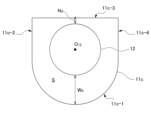
- Fig. 5 is a schematic explanatory diagram showing the shape of the inner peripheral surface of the fixed body 11c and the positional relationship between the fixed body 11c and the rotor 12 in the rotary connector device according to the modified example 3.
- Fig. 5 is a cross-sectional view of a cross section perpendicular to the rotation axis O12 of the rotor 12, and shows the shapes of the fixed body 11c and the rotor 12 when viewed in plan.
- the fixed body 11c in the third modification has an inner circumferential surface that is shaped like a cylinder, with portions 11c-1 and 11c-2, 11c-3, and 11c-4 corresponding to three of the four possible sides that constitute a rectangular parallelepiped.
- the gap between the inner circumferential surface of the fixed body 11c in the area corresponding to cylindrical portion 11c-1 and the outer circumferential surface of the rotating body 12 is wide (the widest point is the portion indicated by the arrow Wc), and the gap between the inner circumferential surface of the fixed body 11c in the area corresponding to portion 11c-2 and the outer circumferential surface of the rotating body 12 is narrow (the narrowest point is the portion indicated by the arrow Nc, which is the center of the area corresponding to portion 11c-2).
- the narrowest point is the portion indicated by the arrow Nc, which is the center of the area corresponding to portion 11c-2).
- Fig. 6 is a schematic explanatory diagram showing the shape of the inner peripheral surface of the fixed body 11d and the positional relationship between the fixed body 11d and the rotor 12 in the rotary connector device according to the modified example 4.
- Fig. 6 is a cross-sectional view of a cross section perpendicular to the rotation axis O12 of the rotor 12, and shows the shapes of the fixed body 11d and the rotor 12 when viewed in plan.
- the fixed body 11d in the fourth modification has the same shape as the fixed body 11 in the above embodiment described with reference to Fig. 1, but the position of the rotation axis of the rotating body 12 is shifted from the position of symbol O in the above embodiment to the position of symbol O 12 on the right side in the drawing. In this way, the present invention does not necessarily have to be a symmetrical figure as a whole.
- the gap between the inner circumferential surface of the fixed body 11d and the outer circumferential surface of the rotating body 12 in the area on the left side of the drawing is wide (the widest point is the arrow Wd), and the gap between the inner circumferential surface of the fixed body 11d and the outer circumferential surface of the rotating body 12 in the area slightly above and to the right of the drawing is narrow (the narrowest point is the arrow Nd).
- Fig. 7 is a schematic explanatory diagram showing the shape of the inner peripheral surface of the fixed body 11e and the positional relationship between the fixed body 11e and the rotor 12 in the rotary connector device according to the modified example 5.
- Fig. 7 is a cross-sectional view of a cross section perpendicular to the rotation axis O12 of the rotor 12, and shows the shapes of the fixed body 11e and the rotor 12 when viewed in plan.
- the fixed body 11e in variant 5 has an inner circumferential surface that is shaped like a pair of cylinders 11e-1 and 11e-3 and a pair of flat plate-like portions 11e-2 and 11e-4 that connect both ends of the cylindrical portions.
- the gap between the inner circumferential surface of the fixed body 11e and the outer circumferential surface of the rotating body 12 is the widest at the circumferential position of the storage space S at the connection between the pair of cylindrical portions 11e-1, 11e-3 and the pair of plate-like portions 11e-2, 11e-4 (arrow We portion), and the gap between the inner circumferential surface of the fixed body 11e and the outer circumferential surface of the rotating body 12 near the center of each of the areas corresponding to the pair of cylindrical portions 11e-1, 11e-3 is narrow (the narrowest point is the center of each of the areas corresponding to the pair of cylindrical portions 11e-1, 11e-3, arrow Ne portion).
- Fig. 8 is a schematic explanatory diagram showing the shape of the inner peripheral surface of the fixed body 11f and the positional relationship between the fixed body 11f and the rotor 12 in the rotary connector device according to the modified example 6.
- Fig. 8 is a cross-sectional view of a cross section perpendicular to the rotation axis O12 of the rotor 12, and shows the shapes of the fixed body 11f and the rotor 12 when viewed in plan.
- the fixed body 11f in the sixth modification has an inner peripheral surface shaped like an elliptical cylinder, and the position of the central axis of the inner peripheral surface of the fixed body 11f coincides with the position of the rotation axis of the rotor 12 (both are indicated by the symbol O12 ). Therefore, the vicinity of both ends of the long axis of the inner peripheral surface of the fixed body 11f is away from the outer periphery of the rotor 12, and the vicinity of both ends of the short axis is close to the outer periphery of the rotor 12.
- Fig. 9 is a schematic explanatory diagram showing the shape of the inner peripheral surface of the fixed body 11g and the positional relationship between the fixed body 11g and the rotor 12 in the rotary connector device according to the modified example 7.
- Fig. 9 is a cross-sectional view of a cross section perpendicular to the rotation axis O12 of the rotor 12, and shows the shapes of the fixed body 11g and the rotor 12 when viewed in plan.
- the fixed body 11g in the seventh modification has an inner peripheral surface shaped like a regular hexagon, with six sides 11g-1 to 11g-6.
- the rotating body 12 is located away from the center of the fixed body 11g toward side 11g-4 (upward in the drawing).
- the gap between the area of side 11g-1 on the inner surface of the fixed body 11g and the outer surface of the rotating body 12 is wide (the widest points are the two arrow Wg points at both ends of side 11g-1), and the gap between the area of side 11g-4 on the inner surface of the fixed body 11g and the outer surface of the rotating body 12 is narrow (the narrowest point is the arrow Ng point at the center of side 11g-4).
- the narrowest point is the arrow Ng point at the center of side 11g-4.
- Fig. 10 is a schematic explanatory diagram showing the shape of the inner peripheral surface of the fixed body 11h and the positional relationship between the fixed body 11h and the rotor 12 in the rotary connector device according to the modified example 8.
- Fig. 10 is a cross-sectional view of a cross section perpendicular to the rotation axis O12 of the rotor 12, and shows the shapes of the fixed body 11h and the rotor 12 when viewed in plan.
- the fixed body 11h in the eighth modification has an inner peripheral surface shaped like a regular pentagon with five sides 11h-1 to 11h-5, and the position of the central axis of the inner peripheral surface of the fixed body 11h coincides with the position of the rotation axis of the rotating body 12 (both are indicated by the symbol O12 ).
- the distance between the regular polygonal fixed body 11h and the circular rotating body 12, whose centers are coincident varies in the circumferential direction.
- the space between the inner surface of the fixed body 11h and the outer surface of the rotating body 12 is the widest of the five vertices of the inner surface of the fixed body 11h (five points indicated by arrows Wh), and the narrowest points are in the areas between those vertices (the narrowest points are the five points indicated by arrows Nh at the centers of each side 11h-1 to 11h-5).
- the narrowest points are the five points indicated by arrows Nh at the centers of each side 11h-1 to 11h-5.
- Fig. 11 is a schematic explanatory diagram showing the shape of the inner peripheral surface of the fixed body 11j and the positional relationship between the fixed body 11j and the rotor 12 in a rotary connector device according to Modification 9.
- Fig. 11 is a cross-sectional view of a cross section perpendicular to the rotation axis O12 of the rotor 12, and shows the shapes of the fixed body 11j and the rotor 12 when viewed in plan.
- the fixed body 11j in the modified example 9 has an inner peripheral surface formed of a cylindrical portion 11j-1 and three flat plate-like portions 11j-2, 11j-3, and 11j-4 that connect both ends of the cylindrical portion 11j-1 and are connected in order.
- the position of the central axis of the inner peripheral surface of the cylindrical portion 11j-1 of the fixed body 11j coincides with the position of the rotation axis of the rotating body 12 (both are indicated by the symbol O 12 ).
- the central portion 11j-3 is the longest of the three flat plate-like portions, and the portions 11j-2 and 11j-4 have the same length and form the same obtuse angle with the portion 11j-3.
- the fixed body 11j and the rotating body 12 in the modified example 9 are symmetrical on the left and right sides of the drawing with respect to a straight line passing through the point O 12 .
- the distance between the inner surface of the fixed body 11j in the area corresponding to the cylindrical portion 11a-1 and the outer surface of the rotating body 12 is constant, and there is a wide portion (arrow Wj portion) and a narrow portion (the narrowest portion is arrow Nj portion at the center of side 11j-3) between the area of the inner surface of the fixed body 11j and the outer surface of the rotating body 12.
- Wj portion wide portion
- Nj portion narrowest portion
- the shape of the inner circumferential surface of the fixed body and the positional relationship between the fixed body and the rotating body are not limited to the configurations of the above embodiments and modified examples.
- regular pentagons and regular hexagons are given as examples in modified examples 7 and 8 above, other polygons are acceptable, and it is not necessary that the shape is a regular polygon.
- the fixed body may have an inner circumferential surface of any shape, such as an asymmetric shape or an irregular shape.
Landscapes
- Steering Controls (AREA)
Priority Applications (3)
| Application Number | Priority Date | Filing Date | Title |
|---|---|---|---|
| JP2025539348A JPWO2025033305A1 (https=) | 2023-08-04 | 2024-08-01 | |
| CN202480042963.XA CN121420432A (zh) | 2023-08-04 | 2024-08-01 | 旋转连接器装置 |
| KR1020267002185A KR20260039708A (ko) | 2023-08-04 | 2024-08-01 | 회전 커넥터 장치 |
Applications Claiming Priority (4)
| Application Number | Priority Date | Filing Date | Title |
|---|---|---|---|
| JP2023128118 | 2023-08-04 | ||
| JP2023-128118 | 2023-08-04 | ||
| JP2023204049 | 2023-12-01 | ||
| JP2023-204049 | 2023-12-01 |
Publications (1)
| Publication Number | Publication Date |
|---|---|
| WO2025033305A1 true WO2025033305A1 (ja) | 2025-02-13 |
Family
ID=94533830
Family Applications (1)
| Application Number | Title | Priority Date | Filing Date |
|---|---|---|---|
| PCT/JP2024/027471 Pending WO2025033305A1 (ja) | 2023-08-04 | 2024-08-01 | 回転コネクタ装置 |
Country Status (4)
| Country | Link |
|---|---|
| JP (1) | JPWO2025033305A1 (https=) |
| KR (1) | KR20260039708A (https=) |
| CN (1) | CN121420432A (https=) |
| WO (1) | WO2025033305A1 (https=) |
Citations (4)
| Publication number | Priority date | Publication date | Assignee | Title |
|---|---|---|---|---|
| JPH0177291U (https=) * | 1987-11-13 | 1989-05-24 | ||
| JPH0177290U (https=) * | 1987-11-13 | 1989-05-24 | ||
| JPH01148688U (https=) * | 1988-04-04 | 1989-10-16 | ||
| JPH07169519A (ja) | 1993-12-16 | 1995-07-04 | Matsushita Electric Ind Co Ltd | フラットケーブル |
-
2024
- 2024-08-01 JP JP2025539348A patent/JPWO2025033305A1/ja active Pending
- 2024-08-01 WO PCT/JP2024/027471 patent/WO2025033305A1/ja active Pending
- 2024-08-01 KR KR1020267002185A patent/KR20260039708A/ko active Pending
- 2024-08-01 CN CN202480042963.XA patent/CN121420432A/zh active Pending
Patent Citations (4)
| Publication number | Priority date | Publication date | Assignee | Title |
|---|---|---|---|---|
| JPH0177291U (https=) * | 1987-11-13 | 1989-05-24 | ||
| JPH0177290U (https=) * | 1987-11-13 | 1989-05-24 | ||
| JPH01148688U (https=) * | 1988-04-04 | 1989-10-16 | ||
| JPH07169519A (ja) | 1993-12-16 | 1995-07-04 | Matsushita Electric Ind Co Ltd | フラットケーブル |
Also Published As
| Publication number | Publication date |
|---|---|
| KR20260039708A (ko) | 2026-03-20 |
| CN121420432A (zh) | 2026-01-27 |
| JPWO2025033305A1 (https=) | 2025-02-13 |
Similar Documents
| Publication | Publication Date | Title |
|---|---|---|
| JP6883012B2 (ja) | ハブ装置および関連システム | |
| JP4868290B2 (ja) | ダブルステータ型インホイールモータ | |
| KR101375985B1 (ko) | 선회 장치 및 그것을 갖는 다관절 로봇 | |
| EP2597734B1 (en) | Rotary connector device | |
| CN104659950A (zh) | 马达 | |
| JP2006199251A (ja) | 発電ハブ用アダプタ | |
| WO2025033305A1 (ja) | 回転コネクタ装置 | |
| US12334695B2 (en) | Rotary connector device | |
| KR100454401B1 (ko) | 회전커넥터 | |
| JPH086672Y2 (ja) | ステアリングホイールの回動伝達装置 | |
| JPH08180950A (ja) | ハンドルとステアリングコラム間の電気的接続装置 | |
| JP3718616B2 (ja) | ステアリング装置への回転コネクタの取り付け構造 | |
| WO2024204523A1 (ja) | 回転コネクタ装置 | |
| JP4892677B2 (ja) | 回転体支持機構 | |
| JP5133835B2 (ja) | ステアリングロールコネクタ及びステアリングホイールの取付構造 | |
| US20230015631A1 (en) | Rotary connector device | |
| JP3556135B2 (ja) | 車載用回転コネクタ | |
| JP2023021694A (ja) | 走行ユニット及び車両 | |
| JP2025023786A (ja) | 回転コネクタ装置 | |
| KR101899652B1 (ko) | 트라이포드 타입 등속조인트를 구비하는 허브 일체형 등속 조인트 모듈 | |
| JP6678683B2 (ja) | テープ集合体、回転コネクタ及びテープ集合体の製造方法 | |
| JP7717573B2 (ja) | 回転コネクタ装置 | |
| JP2008221974A (ja) | ステアリングロールコネクタ | |
| CN115252148B (zh) | 器械操作臂的驱动设备及手术机器人用的手术器械 | |
| WO2023189339A1 (ja) | ステアリング装置およびステアリング装置の製造方法 |
Legal Events
| Date | Code | Title | Description |
|---|---|---|---|
| 121 | Ep: the epo has been informed by wipo that ep was designated in this application |
Ref document number: 24851730 Country of ref document: EP Kind code of ref document: A1 |
|
| ENP | Entry into the national phase |
Ref document number: 2025539348 Country of ref document: JP Kind code of ref document: A |
|
| WWE | Wipo information: entry into national phase |
Ref document number: 2025539348 Country of ref document: JP |
|
| WWE | Wipo information: entry into national phase |
Ref document number: 2024851730 Country of ref document: EP |
|
| NENP | Non-entry into the national phase |
Ref country code: DE |