WO2025032894A1 - 速度検出装置、速度検出システム及び速度検出方法 - Google Patents
速度検出装置、速度検出システム及び速度検出方法 Download PDFInfo
- Publication number
- WO2025032894A1 WO2025032894A1 PCT/JP2024/015849 JP2024015849W WO2025032894A1 WO 2025032894 A1 WO2025032894 A1 WO 2025032894A1 JP 2024015849 W JP2024015849 W JP 2024015849W WO 2025032894 A1 WO2025032894 A1 WO 2025032894A1
- Authority
- WO
- WIPO (PCT)
- Prior art keywords
- speed
- sensor
- detection device
- speed detection
- selection unit
- Prior art date
- Legal status (The legal status is an assumption and is not a legal conclusion. Google has not performed a legal analysis and makes no representation as to the accuracy of the status listed.)
- Pending
Links
Images




Classifications
-
- B—PERFORMING OPERATIONS; TRANSPORTING
- B60—VEHICLES IN GENERAL
- B60L—PROPULSION OF ELECTRICALLY-PROPELLED VEHICLES; SUPPLYING ELECTRIC POWER FOR AUXILIARY EQUIPMENT OF ELECTRICALLY-PROPELLED VEHICLES; ELECTRODYNAMIC BRAKE SYSTEMS FOR VEHICLES IN GENERAL; MAGNETIC SUSPENSION OR LEVITATION FOR VEHICLES; MONITORING OPERATING VARIABLES OF ELECTRICALLY-PROPELLED VEHICLES; ELECTRIC SAFETY DEVICES FOR ELECTRICALLY-PROPELLED VEHICLES
- B60L3/00—Electric devices on electrically-propelled vehicles for safety purposes; Monitoring operating variables, e.g. speed, deceleration or energy consumption
-
- B—PERFORMING OPERATIONS; TRANSPORTING
- B61—RAILWAYS
- B61L—GUIDING RAILWAY TRAFFIC; ENSURING THE SAFETY OF RAILWAY TRAFFIC
- B61L25/00—Recording or indicating positions or identities of vehicles or trains or setting of track apparatus
- B61L25/02—Indicating or recording positions or identities of vehicles or trains
- B61L25/04—Indicating or recording train identities
-
- G—PHYSICS
- G01—MEASURING; TESTING
- G01P—MEASURING LINEAR OR ANGULAR SPEED, ACCELERATION, DECELERATION, OR SHOCK; INDICATING PRESENCE, ABSENCE, OR DIRECTION, OF MOVEMENT
- G01P3/00—Measuring linear or angular speed; Measuring differences of linear or angular speeds
- G01P3/36—Devices characterised by the use of optical means, e.g. using infrared, visible, or ultraviolet light
-
- G—PHYSICS
- G01—MEASURING; TESTING
- G01S—RADIO DIRECTION-FINDING; RADIO NAVIGATION; DETERMINING DISTANCE OR VELOCITY BY USE OF RADIO WAVES; LOCATING OR PRESENCE-DETECTING BY USE OF THE REFLECTION OR RERADIATION OF RADIO WAVES; ANALOGOUS ARRANGEMENTS USING OTHER WAVES
- G01S13/00—Systems using the reflection or reradiation of radio waves, e.g. radar systems; Analogous systems using reflection or reradiation of waves whose nature or wavelength is irrelevant or unspecified
- G01S13/02—Systems using reflection of radio waves, e.g. primary radar systems; Analogous systems
- G01S13/06—Systems determining position data of a target
- G01S13/08—Systems for measuring distance only
- G01S13/32—Systems for measuring distance only using transmission of continuous waves, whether amplitude-, frequency-, or phase-modulated, or unmodulated
- G01S13/34—Systems for measuring distance only using transmission of continuous waves, whether amplitude-, frequency-, or phase-modulated, or unmodulated using transmission of continuous, frequency-modulated waves while heterodyning the received signal, or a signal derived therefrom, with a locally-generated signal related to the contemporaneously transmitted signal
-
- G—PHYSICS
- G01—MEASURING; TESTING
- G01S—RADIO DIRECTION-FINDING; RADIO NAVIGATION; DETERMINING DISTANCE OR VELOCITY BY USE OF RADIO WAVES; LOCATING OR PRESENCE-DETECTING BY USE OF THE REFLECTION OR RERADIATION OF RADIO WAVES; ANALOGOUS ARRANGEMENTS USING OTHER WAVES
- G01S13/00—Systems using the reflection or reradiation of radio waves, e.g. radar systems; Analogous systems using reflection or reradiation of waves whose nature or wavelength is irrelevant or unspecified
- G01S13/02—Systems using reflection of radio waves, e.g. primary radar systems; Analogous systems
- G01S13/50—Systems of measurement based on relative movement of target
- G01S13/58—Velocity or trajectory determination systems; Sense-of-movement determination systems
- G01S13/60—Velocity or trajectory determination systems; Sense-of-movement determination systems wherein the transmitter and receiver are mounted on the moving object, e.g. for determining ground speed, drift angle, ground track
-
- G—PHYSICS
- G01—MEASURING; TESTING
- G01S—RADIO DIRECTION-FINDING; RADIO NAVIGATION; DETERMINING DISTANCE OR VELOCITY BY USE OF RADIO WAVES; LOCATING OR PRESENCE-DETECTING BY USE OF THE REFLECTION OR RERADIATION OF RADIO WAVES; ANALOGOUS ARRANGEMENTS USING OTHER WAVES
- G01S13/00—Systems using the reflection or reradiation of radio waves, e.g. radar systems; Analogous systems using reflection or reradiation of waves whose nature or wavelength is irrelevant or unspecified
- G01S13/88—Radar or analogous systems specially adapted for specific applications
- G01S13/93—Radar or analogous systems specially adapted for specific applications for anti-collision purposes
- G01S13/931—Radar or analogous systems specially adapted for specific applications for anti-collision purposes of land vehicles
Definitions
- the present invention relates to a speed detection device, a speed detection system, and a speed detection method.
- trains received location information from a ground coil installed between a pair of rails, and calculated their location by adding the amount of movement obtained from the number of rotations of the wheels to that information and sequentially calculating it.
- the tachograph used to measure the number of rotations of the wheels makes it difficult to make accurate measurements when the wheel slips or slides, which causes a loss of adhesion between the rail and the wheels, occur.
- Patent Document 1 discloses the following speed detection device.
- the speed measuring device 1 is installed under the floor of the vehicle, and has a transmitting function of irradiating electromagnetic waves (irradiated waves) onto the rail 7 (or, more broadly, the track including the rail 7), and a receiving function of acquiring the electromagnetic waves (reflected waves) that return after hitting the rail 7.
- the transmitting function and the receiving function may each be implemented by independent antennas, or may be implemented by a single antenna having a transmitting and receiving function.
- the speed measurement device 1 also has a speed calculation function that inputs the reflected waves acquired by the above-mentioned receiving function to a calculation unit, and the calculation unit calculates a train speed signal based on the frequency of the irradiated wave and the frequency of the reflected wave.
- the speed calculation function of the speed measurement device 1 utilizes the fact that the frequencies of the electromagnetic waves irradiated to the rail 7 (irradiated waves) and the electromagnetic waves reflected by the rail 7 (reflected waves) differ due to the Doppler effect when a train is running, and calculates a speed signal based on this frequency difference.
- the speed measuring device disclosed in Patent Document 1 employs a millimeter wave radar called a CW (Continuous Wave) type that emits radio waves at a constant frequency.
- CW Continuous Wave
- the CW type millimeter wave radar is irradiated not only to the rail itself but also to the rail bed, and detects the speed including the reflected wave from the rail bed. For this reason, there was a problem with the detection accuracy of the speed in areas where the radar reflection conditions of the road surface are different, such as pit lines, bridges, and puddles. Therefore, an object of the present invention is to provide a technology that enables accurate speed detection regardless of the radar reflection conditions of the road surface, from low speed ranges to high speed ranges.
- one representative speed detection device of the present invention is a speed detection device including a speed sensor and a sensor selection unit,
- the speed sensor is capable of detecting speed by a CW (Continuous Wave) method and an FMCW (Frequency Modulation Continuous Wave) method
- the sensor selection unit selects an FMCW type speed sensor below a certain speed, and selects a CW type speed sensor in any other speed range.
- FIG. 1 is a diagram illustrating an example of a speed detection device mounted on a train.
- FIG. 2 is a diagram for explaining the positional relationship between the millimeter wave speed sensor and the road surface.
- FIG. 3 is a diagram for explaining the positional relationship between the millimeter wave speed sensor and the road surface.
- FIG. 4 is a diagram for explaining the processing of the millimeter wave velocity sensor of the first embodiment.
- FIG. 5 is a diagram for explaining a process when the millimeter wave velocity sensor described in FIG. 4 is used in a CW system.
- FIG. 6 is a diagram for explaining an example of switching the type of sensor to be applied depending on the running speed of a train.
- FIG. 7 is a diagram illustrating an example of installation of a speed detection device according to the second embodiment.
- FIG. 8 is a flow chart showing the mode switching logic of the first embodiment.
- FIG. 9 is a diagram for explaining a situation in which a train consisting of four cars approaches a section that has a bridge and a puddle.
- FIG. 10 is a table illustrating three conditions in the second embodiment.
- FIG. 11 is a diagram for explaining a situation in which a train consisting of a five-car train equipped with three speed detection devices approaches a section that includes a bridge and a puddle.
- first element or component discussed below could also be referred to as a second element or component without departing from the teachings of the inventive concept.
- position, size, shape, range, etc. of each component shown in the drawings may not represent the actual position, size, shape, range, etc. Therefore, the present invention is not necessarily limited to the position, size, shape, range, etc. disclosed in the drawings.
- Millimeter wave sensors come in a variety of types, including CW type, which emits millimeter waves of a fixed frequency and detects speed from the change in frequency between the emitted wave and the reflected wave (Doppler effect), and FMCW type, which varies the frequency of the emitted radio waves within a fixed frequency band.
- CW type which emits millimeter waves of a fixed frequency and detects speed from the change in frequency between the emitted wave and the reflected wave (Doppler effect)
- FMCW type which varies the frequency of the emitted radio waves within a fixed frequency band.
- the CW method detects the speed of an object illuminated with millimeter waves from the Doppler effect of the emitted and reflected waves, but it cannot calculate the distance from the sensor to the illuminated object. For this reason, the CW method cannot distinguish between waves reflected from the rail and those reflected from the trackbed, and speed detection accuracy may decrease if the trackbed or road surface environment changes.
- the FMCW method emits millimeter waves whose frequency changes at a constant rate, and can calculate the distance from the sensor to the target from the frequency deviation that occurs due to the time difference between the emitted wave and the reflected wave.
- This makes it possible to separate the signals of multiple targets based on distance information, and to analyze the primary reflected wave from the signal that is determined to be a rail. This makes it possible to accurately calculate the speed of the target.
- speed measurement is based on a change in distance information, i.e., a change in phase with respect to the above-mentioned frequency deviation.
- vmax shown in the following formula (1) is the upper limit of the measured speed.
- the FMCW method requires a larger computational load for calculation than the CW method, making it less suitable for measurements in high-speed ranges.
- the speed range of high-speed trains is wide, from 0 to 400 km/h, and there was a demand for a speed detection method that could accurately detect speed across this speed range, even under various road surface conditions.
- a train 100 is a vehicle that is assumed to operate on tracks with various road surface conditions at or outside a station.
- a train is composed of a plurality of cars coupled together, but in Fig. 1, for the sake of simplicity, only the configuration of a car (the leading car) that constitutes the train is shown.
- FIG. 1 shows an example in which the train position recognition system that measures the speed of the vehicle is installed in the leading vehicle, in the train position recognition system according to the present invention, the speed measuring device may be installed in another vehicle. As shown in FIG.
- a train position recognition system 102 is mounted on a train 100 running on rails 101 , and the train position recognition system is composed of a speed detection device 103 and an on-board control device 104 . Furthermore, the speed detection device 103 includes a millimeter wave speed sensor 106 and a sensor selection unit 107 . In addition, the on-board control device can obtain the position at any point using a transponder (not shown) installed on the ground, and can calculate the traveling distance from any point using the distance calculated from the speed information obtained from the speed detection device.
- Fig. 2 is a diagram illustrating the positional relationship between the millimeter wave speed sensor 106, the rail 101, and the track bed when the rail 101 is installed at a position substantially at the same height as the track bed 220.
- the millimeter wave speed sensor 106 is fixed inside a housing 205, and includes a lens 207 that controls the irradiation range of the electromagnetic waves, and a transparent window 208 for irradiating the electromagnetic waves of the millimeter wave sensor to the outside of the speed measuring device, and is installed under the vehicle such that the rail 101 is included in the irradiation range 214 of the electromagnetic waves irradiated from the millimeter wave speed sensor 106.
- wheels 209 are shown to make it easier to understand the relationship between the range of electromagnetic waves emitted from millimeter wave speed sensor 106 and the rails, but this does not mean that the wheels are located within the range of electromagnetic waves.
- Millimeter wave speed sensor 106 is not installed directly above wheel 209, but is installed in a position shifted in the forward/rearward direction of the traveling direction from the position directly above wheel 209, and it is desirable that the electromagnetic waves emitted from the millimeter wave speed sensor are irradiated from an oblique direction toward the top of the rail.
- the distance of the electromagnetic wave irradiated from the millimeter wave velocity sensor to the rail top portion 210a is shown as h 1
- the distance of the electromagnetic wave irradiated to the rail bottom portion 210b is shown as h 2
- the millimeter-wave speed sensor is disposed at the inner end of the rail top when the vehicle and the ground are horizontal, but the positions of the center of the millimeter-wave speed sensor and the rail top are not limited to this, and the center of the millimeter-wave speed sensor may be the center of the rail top or the outer end of the rail top.
- the millimeter-wave speed sensor irradiates electromagnetic waves to one rail, but the number and positions of the millimeter-wave sensors are not limited to this, and for example, millimeter-wave sensors may be installed on both the left and right rails.
- FIG. 3 differs from FIG. 2 in that the rail 101 is not placed on the track bed 220 of FIG. 2, but is placed on a member 322 that raises the roadbed 320.
- the rail 101 is not placed on the track bed 220 of FIG. 2, but is placed on a member 322 that raises the roadbed 320.
- the rail is installed on a member 322 that raises the height from the roadbed 320, so the distances from the millimeter wave speed sensor 106 to the irradiation target are the distance h1 to the rail top 210a, the distance h2 to the rail bottom 210b, and the distance h3 to the roadbed 320.
- the roadbed 320 is the ground where staff and the like pass in a rail depot or the like.
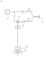
- FIG. 4 is a diagram explaining the processing of the millimeter wave velocity sensor used in the present invention, particularly the processing in the FMCW method.
- the millimeter wave velocity sensor used in the present invention outputs a variable frequency from a synthesizer 415 and emits an irradiated wave 418, which is an electromagnetic wave irradiated from an antenna 416.
- the antenna also receives a reflected wave 419, which is an electromagnetic wave that is the irradiated wave reflected by an object.
- the irradiated wave and the reflected wave are transmitted and received by a single antenna, but a configuration in which the antenna that transmits the irradiated wave and the antenna that receives the reflected wave are separate may also be used.
- the millimeter wave velocity sensor has a mixer 417 that combines two frequencies to generate a signal of a new frequency, and the mixer acquires the irradiated wave output by the synthesizer and the reflected wave received from the antenna, and performs A/D 420 and FFT R 421 processing to convert analog signals to digital signals and perform distance conversion 422. After that, sampling selection 423 is performed to acquire only signals of specific distance components from the distance conversion, and FFT V 424 processing is performed to perform velocity conversion 425. In this figure, FFT processing is performed in the process of performing distance conversion and velocity conversion, but since the processing contents are different, they are divided into FFT R and FFT V, respectively. Furthermore, after the FFT R 421, an SNR measurement unit 430 may be provided to measure and determine whether or not the reflected wave components can be recognized as a signal, and the distance conversion 422 process may be performed only if the signal exceeds a set threshold value.
- Fig. 5 is a diagram for explaining the process when the millimeter wave velocity sensor described in Fig. 4 is used in the CW system.
- the frequency of the irradiated millimeter wave is constant, so a synthesizer 415 generates a millimeter wave of a constant frequency, a mixer 417 acquires the irradiated wave output by the synthesizer and a reflected wave 419 received from the antenna, and executes the processes of A/D 420 and FFT V 424 that convert analog signals and digital signals to perform velocity conversion 425.
- the velocity of the target object is calculated from the change in frequency due to the Doppler effect of the irradiated wave and the reflected wave.
- Fig. 6 is a diagram for explaining an example of switching the sensor method to be applied depending on the running speed of a train.
- Fig. 6 shows the running speed of the train on the vertical axis and the time on the horizontal axis. It shows that when the running speed of the train is equal to or lower than a threshold value Vth , the FMCW method is adopted to detect the running speed of the train, and when the running speed of the train exceeds the threshold value Vth , the CW method is adopted to detect the running speed of the train.
- the sensor selection unit 107 selects the FMCW method for the millimeter wave velocity sensor 106 when the velocity is equal to or lower than a predetermined velocity, and selects the CW method when the velocity is in the other velocity range.
- the predetermined speed that is the threshold for switching can be set to, for example, about 30 Km/h.
- the measurement accuracy decreases in a speed range below about 30 Km/h, so it is reasonable to set this level of speed as the threshold.
- a train travels on a section where the rails are raised above the roadbed 320, such as on a pit line at a vehicle depot, the train travels at a speed of approximately 30 km/h or less.
- the threshold value is not limited to 30 Km/h, and may be set to another speed level.
- the threshold value may be set to the travel speed when traveling on a bridge or in a flooded area, and the threshold value may be set to switch to the FMCW method when it is difficult to measure the speed accurately using the CW method.
- a single threshold is determined, and the CW mode and the FMCW mode are switched depending on whether the traveling speed exceeds the threshold.
- the threshold for switching between the CW mode and the FMCW mode does not necessarily have to be determined as a single threshold, and may be set with hysteresis.
- the threshold value may be set to 20 km/h when transitioning from the CW system mode to the FMCW system mode, and 30 km/h when transitioning from the FMCW system mode to the CW system mode.
- Fig. 7 is a diagram for explaining an example of installation of a speed detection device in the second embodiment.
- a train configuration 700 consisting of one or more cars 710 is provided with a plurality of speed detection devices each equipped with an SNR measurement unit, forming a speed detection system.
- the method of switching between the CW and FMCW modes in each speed detection device can be set based on the speed detected by each speed detection device (103A, 103B) and the accuracy of the reflected wave in the SNR measurement unit (the accuracy of whether the reflected wave components can be recognized as a signal).
- FIG. Fig. 8 is a flow chart showing the mode switching logic of the first embodiment.
- the system judges whether the speed detected by each speed detection device exceeds an arbitrary threshold speed, for example, 30 km/h, and switches between the CW system and the FMCW system. If the speed detection devices near the front and rear ends of the train in the direction of travel are designated as the first and second speed detection devices, respectively, these devices normally detect the same speed, so in the first embodiment, a switching logic such as that described below is applied.
- Step 801 The initial mode when the train starts running may be the CW system or the FMCW system. After the train starts running, the process proceeds to step 803 immediately.
- step 803 the driving speed is calculated based on the initial mode set at the start of driving, and if it exceeds a threshold speed that can be determined arbitrarily, the process proceeds to step 805, and if it does not exceed the threshold speed, the process proceeds to step 807.
- step 805 since the speed exceeds the threshold value, the sensor selection unit is controlled to select the CW method for both the first speed detection device and the second speed detection device. After that, after an arbitrary time interval, the process returns to step 803 and the traveling speed is calculated again.
- Step 807 since the speed does not exceed the threshold speed, the sensor selection unit is controlled to select the FMCW method for both the first speed detection device and the second speed detection device. After that, after an arbitrary time interval, the process returns to step 803 and the traveling speed is calculated again.
- the above is the mode switching control between the CW method and the FMCW method in the first embodiment.
- the interval at which the traveling speed is detected can be set arbitrarily, for example, every 0.5 seconds, or at other time intervals.
- the second example sets a mode switching method between the CW system and the FMCW system when the train comes close to a bridge or a puddle while traveling and the measurement accuracy of the traveling speed is reduced.
- FIG. 9 is a diagram for explaining a situation in which a train consisting of four cars approaches a section with a bridge or a puddle.
- the measurement accuracy of the running speed of the speed detection device 103A installed at the front of the train in the traveling direction may decrease.
- the measurement accuracy of the running speed of the speed detection device 103B installed at the rear end of the train in the traveling direction may decrease.
- the measurement accuracy of the running speed of the speed detection device 103A installed at the front of the train in the traveling direction will recover, and then the measurement accuracy of the running speed of the speed detection device 103B installed at the rear end of the train in the traveling direction will also recover.
- This situation is not limited to bridges, but can also occur in sections where there are puddles on the roadbed.
- each speed detection device should use the CW or FMCW mode to detect speed, and which of the multiple sensors should be used to accurately grasp the traveling speed of the train.
- the conditions under which the measurement accuracy of the traveling speed of each speed detection device is degraded are classified into four types, and the mode of the speed detection device is set according to each condition.
- the four conditions will be described below with reference to Fig. 10.
- the conditions shown in Fig. 10 are based on the premise that the speed detection device measures the traveling speed by the CW method in the initial stage.
- a circle indicates a state in which the speed detection device has good measurement accuracy of the traveling speed
- a cross indicates a state in which the measurement accuracy of the speed detection device has deteriorated.
- the running speed of the train may be calculated based on any speed detection device, or the speeds calculated by the multiple speed detection devices may be averaged to determine the running speed of the train.
- the measurement results by the SNR measurement unit 430 which measures and determines whether the reflected wave components can be recognized as a signal, can be used, but are not limited to this. For example, it is also possible to determine that the measurement accuracy of the traveling speed has decreased using the plot bandwidth width in the CW method or a sudden change in acceleration.
- the specified time until the speed detection device mode of the rear end portion, which has been switched to the FMCW method, is returned to the CW method can be determined by predicting the time until the rear end of the train can pass through the section where there are problems with measurement accuracy. For example, if the length of one car is 30 m and the train consists of 10 cars, the length of the train is approximately 300 m. Therefore, if the train speed is 30 km/h, it can be assumed that the rear end will be able to pass through the section where there are problems with measurement accuracy approximately 36 seconds after the measurement accuracy of the front portion is restored, so the specified time can be set to approximately 36 seconds.
- FIG. 11 is an explanatory diagram of a five-car train in which three speed detection devices 103A, 103B, and 103C are distributed and disposed at three locations, namely, the front, rear, and middle.
- the mode of the speed detection device 103C located in the middle can be temporarily switched to the FMCW method, and if the measurement accuracy of the leading and/or trailing speed detection device recovers, the mode of the speed detection device 103C located in the middle can be returned to the CW method after a predetermined time.
- the running speed of the train may be determined based on the calculation results of the speed detection device 103C arranged in the middle, or may be taken into account by taking a weighted average of the calculation results of the speed detection devices at the front and/or rear ends. In either case, by determining the speed based on the results of multiple speed detection devices, it becomes possible to detect the speed with a higher degree of safety.
Landscapes
- Engineering & Computer Science (AREA)
- Remote Sensing (AREA)
- Radar, Positioning & Navigation (AREA)
- Physics & Mathematics (AREA)
- General Physics & Mathematics (AREA)
- Computer Networks & Wireless Communication (AREA)
- Electromagnetism (AREA)
- Power Engineering (AREA)
- Mechanical Engineering (AREA)
- Life Sciences & Earth Sciences (AREA)
- Sustainable Development (AREA)
- Sustainable Energy (AREA)
- Transportation (AREA)
- Train Traffic Observation, Control, And Security (AREA)
Priority Applications (1)
| Application Number | Priority Date | Filing Date | Title |
|---|---|---|---|
| JP2025539127A JPWO2025032894A1 (https=) | 2023-08-08 | 2024-04-23 |
Applications Claiming Priority (2)
| Application Number | Priority Date | Filing Date | Title |
|---|---|---|---|
| JP2023-129113 | 2023-08-08 | ||
| JP2023129113 | 2023-08-08 |
Publications (1)
| Publication Number | Publication Date |
|---|---|
| WO2025032894A1 true WO2025032894A1 (ja) | 2025-02-13 |
Family
ID=94533876
Family Applications (1)
| Application Number | Title | Priority Date | Filing Date |
|---|---|---|---|
| PCT/JP2024/015849 Pending WO2025032894A1 (ja) | 2023-08-08 | 2024-04-23 | 速度検出装置、速度検出システム及び速度検出方法 |
Country Status (2)
| Country | Link |
|---|---|
| JP (1) | JPWO2025032894A1 (https=) |
| WO (1) | WO2025032894A1 (https=) |
Citations (8)
| Publication number | Priority date | Publication date | Assignee | Title |
|---|---|---|---|---|
| US5087918A (en) * | 1990-04-02 | 1992-02-11 | Delco Electronics Corporation | FMCW/2FD implementation for vehicle near obstacle detection system |
| JP2004069693A (ja) * | 2002-07-26 | 2004-03-04 | Hitachi Ltd | 電波レーダ装置及び車間距離制御装置 |
| JP2014006072A (ja) * | 2012-06-21 | 2014-01-16 | Nec Corp | レーダ装置、目標データ取得方法及び、目標追尾システム |
| JP2014215244A (ja) * | 2013-04-26 | 2014-11-17 | 日本無線株式会社 | レーダ受信装置 |
| JP2015506474A (ja) * | 2012-01-05 | 2015-03-02 | ローベルト ボッシュ ゲゼルシャフト ミット ベシュレンクテル ハフツング | 車両における車輪に依存しない速度測定のための方法及び装置 |
| JP2017211356A (ja) * | 2015-10-20 | 2017-11-30 | 日本信号株式会社 | 検知装置 |
| WO2019145272A1 (de) * | 2018-01-23 | 2019-08-01 | Siemens Aktiengesellschaft | Verfahren und anordnung zur bestimmung der geschwindigkeit eines fahrzeugsx |
| CN111098890A (zh) * | 2019-12-18 | 2020-05-05 | 中铁电气化局集团有限公司 | 一种基于毫米波雷达的列车防撞方法及装置 |
-
2024
- 2024-04-23 WO PCT/JP2024/015849 patent/WO2025032894A1/ja active Pending
- 2024-04-23 JP JP2025539127A patent/JPWO2025032894A1/ja active Pending
Patent Citations (8)
| Publication number | Priority date | Publication date | Assignee | Title |
|---|---|---|---|---|
| US5087918A (en) * | 1990-04-02 | 1992-02-11 | Delco Electronics Corporation | FMCW/2FD implementation for vehicle near obstacle detection system |
| JP2004069693A (ja) * | 2002-07-26 | 2004-03-04 | Hitachi Ltd | 電波レーダ装置及び車間距離制御装置 |
| JP2015506474A (ja) * | 2012-01-05 | 2015-03-02 | ローベルト ボッシュ ゲゼルシャフト ミット ベシュレンクテル ハフツング | 車両における車輪に依存しない速度測定のための方法及び装置 |
| JP2014006072A (ja) * | 2012-06-21 | 2014-01-16 | Nec Corp | レーダ装置、目標データ取得方法及び、目標追尾システム |
| JP2014215244A (ja) * | 2013-04-26 | 2014-11-17 | 日本無線株式会社 | レーダ受信装置 |
| JP2017211356A (ja) * | 2015-10-20 | 2017-11-30 | 日本信号株式会社 | 検知装置 |
| WO2019145272A1 (de) * | 2018-01-23 | 2019-08-01 | Siemens Aktiengesellschaft | Verfahren und anordnung zur bestimmung der geschwindigkeit eines fahrzeugsx |
| CN111098890A (zh) * | 2019-12-18 | 2020-05-05 | 中铁电气化局集团有限公司 | 一种基于毫米波雷达的列车防撞方法及装置 |
Also Published As
| Publication number | Publication date |
|---|---|
| JPWO2025032894A1 (https=) | 2025-02-13 |
Similar Documents
| Publication | Publication Date | Title |
|---|---|---|
| US6360998B1 (en) | Method and apparatus for controlling trains by determining a direction taken by a train through a railroad switch | |
| RU2536271C2 (ru) | Система управления поездом (варианты) | |
| CA2273399C (en) | Apparatus and method for detecting railroad locomotive turns by monitoring truck orientation | |
| US6348889B1 (en) | Radar apparatus | |
| US9610961B2 (en) | Method and device for measuring speed in a vehicle independently of the wheels | |
| JP5003674B2 (ja) | レーダ装置および移動体 | |
| US7317987B2 (en) | Vehicle navigation, collision avoidance and control system | |
| JP4045041B2 (ja) | レーダ装置及びレーダ装置の異常検出方法 | |
| US10621385B2 (en) | Device and method for determining geometry characteristic values of a wheel profile on a rolling wheel of a rail vehicle | |
| RU2577516C2 (ru) | Способ и устройство для обнаружения вращающегося колеса | |
| JP2003146212A (ja) | 列車制御システム及び制御方法 | |
| CN101950018A (zh) | 估算目标物体信息的装置 | |
| CN112485790B (zh) | 基于k波段雷达的轨道非接触式变形高精度测量方法 | |
| JPWO1998007610A1 (ja) | 弾性波を用いた情報生成装置 | |
| CN114735049B (zh) | 一种基于激光雷达的磁浮列车测速定位方法及系统 | |
| JP3761888B2 (ja) | 車載レーダ装置 | |
| US7425917B2 (en) | Radar for detecting the velocity of a target | |
| JP3575334B2 (ja) | Fmcwレーダ装置 | |
| CA2816234A1 (en) | Method for detecting a wheel of a vehicle | |
| WO2025032894A1 (ja) | 速度検出装置、速度検出システム及び速度検出方法 | |
| US20200191941A1 (en) | A system for enhanced object tracking | |
| CN113031606A (zh) | 一种无线虚拟导轨系统以及车辆定位和控制方法 | |
| RU2747818C1 (ru) | Способ определения местоположения поезда по инфраструктуре железнодорожного пути в режиме реального времени | |
| RU2308750C1 (ru) | Способ определения местоположения объектов | |
| US20250012920A1 (en) | Method, device and system for operating a rail vehicle for warning about a possible collision |
Legal Events
| Date | Code | Title | Description |
|---|---|---|---|
| 121 | Ep: the epo has been informed by wipo that ep was designated in this application |
Ref document number: 24851328 Country of ref document: EP Kind code of ref document: A1 |
|
| ENP | Entry into the national phase |
Ref document number: 2025539127 Country of ref document: JP Kind code of ref document: A |
|
| WWE | Wipo information: entry into national phase |
Ref document number: 2025539127 Country of ref document: JP |
|
| NENP | Non-entry into the national phase |
Ref country code: DE |