WO2025028451A1 - ウェアラブルデバイス - Google Patents
ウェアラブルデバイス Download PDFInfo
- Publication number
- WO2025028451A1 WO2025028451A1 PCT/JP2024/026847 JP2024026847W WO2025028451A1 WO 2025028451 A1 WO2025028451 A1 WO 2025028451A1 JP 2024026847 W JP2024026847 W JP 2024026847W WO 2025028451 A1 WO2025028451 A1 WO 2025028451A1
- Authority
- WO
- WIPO (PCT)
- Prior art keywords
- wearable device
- conductive
- sensor
- exposed
- sensor body
- Prior art date
- Legal status (The legal status is an assumption and is not a legal conclusion. Google has not performed a legal analysis and makes no representation as to the accuracy of the status listed.)
- Pending
Links
Images









Classifications
-
- A—HUMAN NECESSITIES
- A61—MEDICAL OR VETERINARY SCIENCE; HYGIENE
- A61B—DIAGNOSIS; SURGERY; IDENTIFICATION
- A61B5/00—Measuring for diagnostic purposes; Identification of persons
- A61B5/02—Detecting, measuring or recording for evaluating the cardiovascular system, e.g. pulse, heart rate, blood pressure or blood flow
-
- A—HUMAN NECESSITIES
- A61—MEDICAL OR VETERINARY SCIENCE; HYGIENE
- A61B—DIAGNOSIS; SURGERY; IDENTIFICATION
- A61B5/00—Measuring for diagnostic purposes; Identification of persons
- A61B5/05—Detecting, measuring or recording for diagnosis by means of electric currents or magnetic fields; Measuring using microwaves or radio waves
- A61B5/053—Measuring electrical impedance or conductance of a portion of the body
- A61B5/0537—Measuring body composition by impedance, e.g. tissue hydration or fat content
-
- A—HUMAN NECESSITIES
- A61—MEDICAL OR VETERINARY SCIENCE; HYGIENE
- A61B—DIAGNOSIS; SURGERY; IDENTIFICATION
- A61B5/00—Measuring for diagnostic purposes; Identification of persons
- A61B5/24—Detecting, measuring or recording bioelectric or biomagnetic signals of the body or parts thereof
- A61B5/25—Bioelectric electrodes therefor
- A61B5/251—Means for maintaining electrode contact with the body
- A61B5/256—Wearable electrodes, e.g. having straps or bands
-
- A—HUMAN NECESSITIES
- A61—MEDICAL OR VETERINARY SCIENCE; HYGIENE
- A61B—DIAGNOSIS; SURGERY; IDENTIFICATION
- A61B5/00—Measuring for diagnostic purposes; Identification of persons
- A61B5/24—Detecting, measuring or recording bioelectric or biomagnetic signals of the body or parts thereof
- A61B5/25—Bioelectric electrodes therefor
- A61B5/279—Bioelectric electrodes therefor specially adapted for particular uses
- A61B5/28—Bioelectric electrodes therefor specially adapted for particular uses for electrocardiography [ECG]
Definitions
- This disclosure relates to wearable devices.
- Patent Document 1 discloses a bioinformation measuring device as this type of wearable device.
- the bioinformation measuring device described in Patent Document 1 comprises a case that houses the device body including a bioinformation detection unit that detects the user's bioinformation, a band that causes the case to be worn by the user, and electrodes provided on the surface of the case or band that comes into contact with the user's body.
- the bioinformation detection unit in Patent Document 1 also comprises an electrocardiogram measurement unit and a pulse wave detection unit.
- the electrodes in contact with the surface of the living body are easily deteriorated due to contact with the surface of the living body and the adhesion of sweat on the surface of the living body.
- the deterioration of the electrodes as described above may require replacement of the entire bioinformation measuring device including the bioinformation detection unit.
- the bioinformation measuring device described in Patent Document 1 even if replacement of components other than the electrodes (e.g., the control unit and pulse wave detection unit) of the device main body as the sensor main body is not required, deterioration of the electrodes may determine the life cycle of the entire device. Therefore, in the bioinformation measuring device of Patent Document 1, there is still room for improvement in terms of the reusability of the sensor main body.
- the bioinformation detection unit described in Patent Document 1 also includes an electrocardiogram measurement unit that utilizes the electrical characteristics of the living body from the electrodes, as well as a pulse wave detection unit that can detect bioinformation other than the electrical characteristics of the living body. In such cases, it is preferable to improve the reusability of the sensor body described above while suppressing any deterioration in the detection accuracy of the detection unit.
- the present disclosure aims to provide a wearable device that can improve the reusability of the sensor body while suppressing a decrease in the detection accuracy of a detection unit that can detect bioinformation other than the electrical characteristics of a living body.
- a wearable device includes: (1) A sensor body including an electrode capable of detecting an electrical characteristic of a living body and a detection unit capable of detecting biological information other than the electrical characteristic of the living body; An attachment part that is detachable from the sensor body and can be attached to a surface of a living body, the attachment portion includes a conductive portion that electrically connects the electrode of the sensor body and the biological surface by contacting the electrode of the sensor body and the biological surface; The attachment portion is a wearable device configured so that the attachment portion on which the sensor body is attached is attached to the biological surface, and so as not to obstruct the space between the detection portion of the sensor body and the biological surface when the electrodes of the sensor body and the biological surface are in a conductive state in which they are conductive via the conductive portion of the attachment portion.
- a wearable device includes: (2) The attachment portion includes a back surface that covers the biological surface in the conductive state, and a front surface opposite to the back surface, the sensor body is detachable from the mounting portion at the front side of the mounting portion, The mounting portion has an opening formed therein, the opening extending from the front side to the rear side, The wearable device according to (1) above, wherein the detection unit of the sensor body is capable of detecting the biometric information through the opening of the attachment unit in the conductive state.
- a wearable device includes: (3) The wearable device according to (2) above, wherein the sensor main body, in the conductive state, enters the opening from the front side of the mounting portion.
- a wearable device includes: (4) The wearable device according to (3) above, wherein the sensor main body, in the conductive state, protrudes from the rear surface of the mounting portion through the opening of the mounting portion.
- a wearable device includes: (5) The conductive portion of the attachment portion is a front exposed portion exposed to the front surface and capable of coming into contact with the electrodes of the sensor body; The wearable device according to any one of (2) to (4) above, further comprising a rear exposed portion exposed on the rear surface and capable of coming into contact with the surface of the living body.
- a wearable device includes: (6) a receiving recess capable of receiving the sensor main body is formed on the front surface of the mounting portion, The wearable device according to (5) above, wherein the front exposed portion of the conductive portion is exposed on the front surface, that is, a bottom surface of the accommodating recess.
- a wearable device includes: (7) a receiving recess capable of receiving the sensor main body is formed on the front surface of the mounting portion, The wearable device according to (5) or (6) above, wherein the front exposed portion of the conductive portion is exposed on a side surface of the accommodating recess on the front surface.
- a wearable device includes: (8)
- the attachment portion is a band body that extends along a circumferential direction of the arm and can be attached to the arm,
- the wearable device according to any one of (5) to (7) above, wherein the rear exposed portion and the front exposed portion of the conductive portion are arranged in overlapping positions in the extension direction of the band body.
- a wearable device includes: (9) The attachment portion is a band body that extends along a circumferential direction of the arm and can be attached to the arm, The wearable device according to any one of (5) to (7) above, wherein the rear exposed portion and the front exposed portion of the conductive portion are arranged in positions that do not overlap in the extension direction of the band body.
- a wearable device includes: (10) The wearable device is described in (9) above, wherein the conductive portion electrically connects the rear exposed portion and the front exposed portion and includes a wiring portion that is embedded in the band body so as not to be exposed to the outside.
- a wearable device includes: (11) The sensor body includes a plurality of the electrodes, The wearable device according to any one of (1) to (10) above, wherein the attachment portion includes a plurality of the conductive portions corresponding to the plurality of electrodes, respectively.
- a wearable device includes: (12) The wearable device according to any one of (1) to (11) above, wherein the detection unit of the sensor main body is a sensor capable of detecting electromagnetic waves or sound waves from a living body.
- a wearable device includes: (13) The wearable device according to (12) above, wherein the detection unit of the sensor main body is an optical pulse wave sensor.
- This disclosure makes it possible to provide a wearable device that can improve the reusability of the sensor body while suppressing deterioration in detection accuracy of a detection unit that can detect bioinformation other than electrical characteristics of a living body.
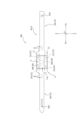
- FIG. 2 is a perspective view of a wearable device according to one embodiment, seen from the front side, illustrating a state in which a sensor main body is attached to a base body.
- 2 is a perspective view of the wearable device shown in FIG. 1 as viewed from the rear side.
- FIG. 2 is a front view of the wearable device shown in FIG. 2 is a diagram showing a state in which the wearable device shown in FIG. 1 is used.
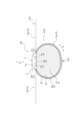
- 2 is a diagram showing a state in which the wearable device shown in FIG. 1 is used.
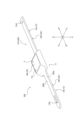
- 2 is an exploded oblique view, seen from the front side, of the wearable device shown in FIG. 1 in a state in which a base body and a sensor body are separated.
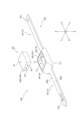
- FIG. 7 is an exploded perspective view of the wearable device shown in FIG. 6 as viewed from the rear side.
- 4 is a cross-sectional view of the wearable device taken along line I-I in FIG. 3 .
- 4 is a cross-sectional view of the wearable device taken along line II-II in FIG. 3 .
- FIG. 2 is a perspective view of a wearable device according to one embodiment, seen from the front side, illustrating a state in which a sensor main body is attached to a base body.
- 11 is an exploded oblique view from the front side showing a state in which a base body and a sensor main body of the wearable device shown in FIG. 10 are separated.
- FIG. 12 is an exploded perspective view of the wearable device shown in FIG.
- FIG. 11 is a diagram showing a state in which the wearable device shown in FIG. 10 is used.
- FIG. 1 is an exploded perspective view of a wearable device according to one embodiment. 16 is a cross-sectional view of the mounting portion of the wearable device shown in FIG. 15. 16 is a diagram showing a contact state between the conductive portion of the base body and the electrodes of the sensor body in the wearable device shown in FIG. 15.
- FIG. 1 and 2 are perspective views of a wearable device 100 as an embodiment of a wearable device according to the present disclosure.
- the wearable device 100 includes an attachment section 1 that can be attached to a biological surface, and a sensor body 3 that can be attached to and detached from the attachment section 1.
- the attachment section 1 of this embodiment is a base body 2 that is attached to the biological surface so as to be interposed between the biological surface and the sensor body 3.
- FIG. 1 is a perspective view of the wearable device 100 from the front side in a state in which the sensor body 3 is attached to the base body 2.
- FIG. 2 is a perspective view of the wearable device 100 from the rear side in a state in which the sensor body 3 is attached to the base body 2.
- FIG. 3 is a front view of the wearable device 100 in a state in which the sensor body 3 is attached to the base body 2.
- FIG. 4 and FIG. 5 are views showing the wearable device 100 in use.
- the wearable device 100 is attached to the surface of the body when in use. As shown in Figures 4 and 5, the wearable device 100 of this embodiment is configured to be used by being wrapped around the arm X of the user. More specifically, the wearable device 100 of this embodiment includes a band body 10 as a base body 2. As shown in Figures 4 and 5, the band body 10 extends circumferentially around the arm X of the user and is attached to the arm X in a state where it is wrapped around the arm X.
- Figures 4 and 5 show an example in which the wearable device 100 is used by being wrapped around the wrist X1 of the user's arm X, but the attachment position of the wearable device 100 is not limited to the wrist X1.
- the wearable device 100 may be used, for example, by being wrapped around the forearm of the user's arm X.
- the wearable device 100 may be used by being wrapped around a biological surface other than the arm X, such as the user's leg.
- the wearable device 100 of this embodiment includes a band body 10 as the base body 2 that is wrapped around the surface of a living body when used, but the base body 2 is not limited to the band body 10.
- the base body 2 may, for example, have an adhesive surface that can be attached to the surface of a living body, and may be attached to the surface of a living body by being attached to the surface of a living body.
- the surface of a living body to which the base body 2 is attached may be a position other than the arm X or leg, such as the chest.
- the wearable device 100 can acquire biometric information while being wrapped around the wrist X1 of the user's arm X. More specifically, the wearable device 100 can acquire biometric information based on electrical characteristics of the living body and other biometric information that is not based on electrical characteristics of the living body.
- bioinformation based on the electrical characteristics of a living organism examples include bioimpedance detected by passing electricity through the living organism, and electrocardiogram information related to the operation of the heart obtained by detecting electrical signals flowing through the living organism.
- bioinformation not based on the electrical characteristics of a living organism examples include pulse wave information and blood pressure information. These are types of bioinformation that can be obtained without passing electricity through the living organism or detecting electrical signals flowing through the living organism.
- the wearable device 100 of this embodiment is configured to be capable of acquiring bioimpedance as bioinformation based on the electrical characteristics of a living organism.
- the wearable device 100 of this embodiment is configured to be capable of acquiring pulse wave information as other bioinformation not based on the electrical characteristics of a living organism.
- the wearable device 100 of this embodiment can acquire the user's bioimpedance and pulse wave information by being wrapped around the user's arm X.
- the wearable device 100 of this embodiment can measure the amount of moisture in the user's wrist X1 by acquiring bioimpedance from the user's wrist X1. It is known that a decline in cardiac function in a living body can cause edema, in which moisture accumulates on or under the skin.
- the wearable device 100 can monitor the amount of moisture in the wrist X1 of a user, such as a heart disease patient, and thus detect a decline in the user's cardiac function at an early stage.
- the wearable device 100 of this embodiment also acquires pulse wave information from the user's wrist X1, thereby making it possible to monitor the user's heart rate in addition to the above-mentioned moisture content of the user. As a result, it is possible to consider the decline in the user's cardiac function from the perspective of fluctuations in heart rate, in addition to the perspective of fluctuations in moisture content.
- the wearable device 100 may be constantly attached to the user for use for a certain period of time, such as a few hours or a few days. In this way, the state of the user's cardiac function can be constantly monitored. This allows for early detection of a decline in the user's cardiac function. However, the wearable device 100 may also be temporarily attached to the user for use in order to ascertain the state of the user's cardiac function at a specified time.
- Figs. 6 and 7 are exploded perspective views of the wearable device 100, showing the base body 2 and the sensor body 3 of the wearable device 100 separated.
- Fig. 6 is an exploded perspective view of the wearable device 100, seen from the front side, in a state in which the base body 2 and the sensor body 3 are separated.
- Fig. 7 is an exploded perspective view of the wearable device 100, seen from the rear side, in a state in which the base body 2 and the sensor body 3 are separated.
- Fig. 8 is a cross-sectional view of the wearable device 100 taken along line I-I in Fig. 3.
- FIG. 9 is a cross-sectional view of the wearable device 100 taken along line II-II in Fig. 3.
- the position of the outer surface of the wrist X1 of the user's arm X, to which the wearable device 100 is attached, is indicated by a dashed line.
- the wearable device 100 includes a base body 2 and a sensor body 3.
- the base body 2 is configured so that it can be attached to the surface of a living body.
- the sensor body 3 is configured so that it can be attached to and detached from the base body 2.
- the sensor body 3 includes electrodes 21 capable of detecting electrical characteristics of a living organism, and a detection unit 23 capable of detecting bioinformation other than electrical characteristics of the living organism.
- the sensor body 3 of this embodiment is capable of acquiring bioimpedance based on the electrical characteristics of the living organism detected by the electrodes 21.
- the detection unit 23 may be a sensor capable of detecting electromagnetic waves or sound waves from the living organism.
- the detection unit 23 of this embodiment is an optical pulse wave sensor that utilizes photoplethysmography.
- the sensor body 3 of this embodiment is capable of acquiring pulse wave information (pulse wave signal) based on the optical pulse wave sensor as the detection unit 23.
- the base body 2 includes a conductive portion 41.
- the conductive portion 41 is configured to be able to conduct the electrode 21 of the sensor body 3 and the biological surface by contacting the electrode 21 of the sensor body 3 and the biological surface.
- the sensor body 3 can be attached to the base body 2 so that the electrode 21 is in contact with the conductive portion 41.
- the base body 2 is attached to the biological surface in a state in which the conductive portion 41 of the base body 2 and the electrode 21 of the sensor body 3 are in contact and conductive.
- the base body 2 of this embodiment is attached to the wrist X1 in a state in which it is wrapped around the wrist X1 of the user (see FIG. 4 and FIG. 5).
- the conductive portion 41 of the base body 2 contacts the outer surface of the wrist X1 as the biological surface.
- the base body 2 is attached to the biological surface, and the electrode 21 of the sensor body 3 and the biological surface are in a conductive state through the conductive portion 41 of the base body 2.
- this state will be simply referred to as a "conductive state”.
- the base body 2 is configured so that, in a conductive state, it does not block the gap between the detection unit 23 of the sensor body 3 and the surface of the living body. Although details will be described later, an opening 50 is formed in the base body 2 of this embodiment (see Figure 7, etc.). As shown in Figure 9, the detection unit 23 of the sensor body 3 can detect pulse wave information as biological information other than the electrical characteristics of the living body through the opening 50 of the base body 2.
- the sensor body 3 is configured to be detachable from the base body 2.
- the electrodes 21 of the sensor body 3 are not in direct contact with the surface of the living body, but are configured to be conductive with the surface of the living body via the conductive portion 41 of the base body 2.
- the sensor body 3 does not have an electrode that directly contacts the living tissue to conduct electricity. This makes it possible to prevent the electrodes 21 of the sensor body 3 from deteriorating due to contact with the surface of the living body or the adhesion of sweat on the surface of the living body.
- the conductive portion 41 of the base body 2 may deteriorate due to contact with the surface of the living body or the adhesion of sweat on the surface of the living body.
- the sensor body 3 can be removed from the base body 2 and only the base body 2 can be replaced. In other words, the sensor body 3 including various electronic components can be reused. In this way, the reusability of the sensor body 3 in the wearable device 100 can be improved.
- the base body 2 is configured so as not to block the gap between the detection unit 23 of the sensor body 3 and the biological surface when in a conductive state. Therefore, even if the base body 2 is interposed between the sensor body 3 and the biological surface, the detection unit 23 can suppress a decrease in the accuracy of detection of biological information.
- the detection unit 23 does not conduct electricity to the biological surface. Therefore, even if the part involved in the detection of biological information by the detection unit 23 comes into direct contact with the skin as the biological surface without being blocked by the base body 2 or is covered with sweat, it is unlikely to deteriorate. Details will be described later, but in this embodiment, the detection window portion 24e of the housing 24 of the sensor body 3 is configured to be able to contact the outer surface of the wrist X1 as the biological surface through the opening 50 (see FIG. 9).
- the wearable device 100 can improve the reusability of the sensor body 3 while preventing a decrease in the detection accuracy of the detection unit 23, which can detect bioinformation other than the electrical characteristics of a living body.
- the wearable device 100 of this embodiment will be described in further detail below.
- the surface facing the living body surface will be described as the "rear” and the surface opposite the rear will be described as the "front”.
- the direction from the rear side to the front side and the direction from the front side to the rear side in the wearable device 100 will be described as the "thickness direction A”.
- the direction perpendicular to the thickness direction A in the wearable device 100 and in which the band body 10 as the base body 2 extends will be described as the “longitudinal direction B”. Also, in this embodiment, the direction perpendicular to the thickness direction A and the longitudinal direction B in the wearable device 100 will be described as the "width direction C”.
- the sensor body 3 of this embodiment includes, in addition to the electrodes 21 and detection unit 23 described above, a housing 24, a control unit 25, a communication unit 26, and a rechargeable battery 27.
- the sensor body 3 of this embodiment has a plurality of electrodes 21. Specifically, the sensor body 3 of this embodiment has four electrodes 21.
- the four electrodes 21 of this embodiment are composed of a pair of electrodes 21a, 21b and another pair of electrodes 21c, 21d.
- the pair of electrodes 21a, 21b is used to obtain the bioimpedance of the user.
- the other pair of electrodes 21c, 21d may be used, for example, to obtain the bioimpedance of the user, similar to the pair of electrodes 21a, 21b.
- the other pair of electrodes 21c, 21d may also be used, for example, as application electrodes that pass a current through a living body.
- the other pair of electrodes 21c, 21d may be used, for example, to correct the measurement value of the bioimpedance obtained through the pair of electrodes 21a, 21b.
- the other pair of electrodes 21c, 21d may be used to improve the measurement accuracy of the measurement value of the bioimpedance obtained through the pair of electrodes 21a, 21b.
- the sensor main body 3 may also be configured not to include the other pair of electrodes 21c, 21d.
- the pair of electrodes 21a, 21b in this embodiment will be referred to as a "pair of detection electrodes 21a, 21b," and the other pair of electrodes 21c, 21d in this embodiment will be referred to as a “pair of auxiliary electrodes 21c, 21d.”
- electrodes 21 when there is no particular need to distinguish between the four electrodes 21a to 21d, they will simply be referred to as "electrodes 21.”
- the electrode 21 is a dry electrode made of, for example, rubber or metal. However, it is preferable that the electrode 21 is made of a metal with high electrical conductivity.
- the electrode 21 is exposed to the outside of the housing 24, which will be described later.
- the pair of detection electrodes 21a, 21b in this embodiment are arranged side by side in the longitudinal direction B.
- the pair of detection electrodes 21a, 21b are "arranged side by side in the longitudinal direction B" means that there is at least one imaginary straight line (e.g., imaginary straight line L1 in FIG. 3) that is parallel to the longitudinal direction B and passes through the pair of detection electrodes 21a, 21b in a plan view of the wearable device 100 along the thickness direction A (see FIG. 3).
- the pair of detection electrodes 21a, 21b can be brought into contact with approximately equal positions in the longitudinal direction of the user's arm X and different positions in the circumferential direction of the user's arm X.
- the pair of detection electrodes 21a, 21b can detect bioimpedance in one cross section of the user's arm X that is approximately perpendicular to the longitudinal direction of the arm X. Therefore, it becomes easier to monitor changes in the moisture content of the user's arm X in association with changes in the outer diameter of the arm due to edema, etc.
- the pair of auxiliary electrodes 21c, 21d in this embodiment are also arranged side by side in the longitudinal direction B.
- the pair of auxiliary electrodes 21c, 21d being "arranged side by side in the longitudinal direction B" means that there is at least one imaginary straight line (e.g., imaginary straight line L2 in FIG. 3) that is parallel to the longitudinal direction B and passes through the pair of auxiliary electrodes 21c, 21d in a plan view of the wearable device 100 along the thickness direction A (see FIG. 3).
- the pair of detection electrodes 21a, 21b and the pair of auxiliary electrodes 21c, 21d are arranged at different positions in the width direction C, but this configuration is not limited to this.
- the pair of detection electrodes 21a, 21b and the pair of auxiliary electrodes 21c, 21d may be arranged side by side in the longitudinal direction B.
- the four electrodes 21a to 21d may be arranged side by side in the longitudinal direction B.
- the pair of detection electrodes 21a, 21b and the pair of auxiliary electrodes 21c, 21d are arranged side by side in the longitudinal direction B, but this configuration is not limited to this.
- the pair of detection electrodes 21a, 21b and the pair of auxiliary electrodes 21c, 21d may be arranged side by side in the width direction C at the same position or different positions in the longitudinal direction B.
- it is preferable that the pair of detection electrodes 21a, 21b are arranged side by side in the longitudinal direction B.
- the detection unit 23 of this embodiment is an optical pulse wave sensor that uses photoplethysmography.
- the detection unit 23 of this embodiment includes an optical transmitter/receiver 23a that can transmit and receive optical signals through a detection window 24e of the housing 24, which will be described later.
- the housing 24 is an exterior member of the sensor body 3.
- the housing 24 is a rectangular box made of resin that defines an internal space 24a.
- the detection unit 23, the control unit 25, the communication unit 26, and the rechargeable battery 27 are housed in the internal space 24a of the housing 24.
- the housing 24 of this embodiment includes a top wall portion 24b, a bottom wall portion 24c, and a side wall portion 24d.
- the internal space 24a of the housing 24 is defined by the top wall portion 24b, the bottom wall portion 24c, and the side wall portion 24d.
- the top wall portion 24b and the bottom wall portion 24c are arranged opposite each other in the thickness direction A.
- the periphery of the internal space 24a in a direction perpendicular to the thickness direction A is defined by the side wall portion 24d.
- the side wall portion 24d of this embodiment includes a flat first side plate portion 24d1 and a flat second side plate portion 24d2 that face each other in the longitudinal direction B, and a flat third side plate portion 24d3 and a flat fourth side plate portion 24d4 that face each other in the width direction C.
- the bottom wall 24c in this embodiment includes a flat bottom wall body 24c1 that is connected to the side wall 24d and has an opening in the center, and a cylindrical protrusion 24c2 that rises from the inner edge of the bottom wall body 24c1.
- the tip of the protrusion 24c2 is closed by a tip wall 24c3.
- the electrode 21 of this embodiment is held in the housing 24 so as to be exposed to the outside of the housing 24. Specifically, the electrode 21 of this embodiment is exposed to the outside from the bottom wall portion 24c of the housing 24. More specifically, the electrode 21 of this embodiment is exposed to the outside from the bottom wall portion 24c so as to protrude from the outer surface of the bottom wall main body portion 24c1 of the bottom wall portion 24c of the housing 24.
- the protruding portion 24c2 of this embodiment protrudes further from the bottom wall main body portion 24c1 than the electrode 21.
- the protruding amount T1 of the protruding portion 24c2 from the bottom wall main body portion 24c1 is greater than the protruding amount T2 of the electrode 21 from the bottom wall main body portion 24c1 (see FIG. 9).
- the housing 24 of this embodiment has a detection window 24e that is used for detection of biological information by the detection unit 23 housed in the internal space 24a.
- the detection unit 23 of this embodiment is an optical pulse wave sensor, and the detection unit 23 can detect pulse wave information by the optical transmission/reception unit 23a transmitting and receiving optical signals through the detection window 24e of the housing 24.
- the detection window 24e of this embodiment may be formed, for example, from a transparent resin material.
- the detection window 24e of this embodiment is formed in the tip wall 24c3 of the bottom wall 24c of the housing 24.
- the detection window 24e of this embodiment is disposed in an area surrounded by the four electrodes 21a to 21d in a plan view of the sensor body 3 along the thickness direction A.
- the position of the detection window 24e is not limited to the position of this embodiment.
- the control unit 25 executes operation instructions and the like for each part of the wearable device 100.
- the control unit 25 is configured with a processor such as a CPU or MPU. More specifically, the control unit 25 of this embodiment has a storage unit such as a ROM (read only memory) or a RAM (random access memory). The storage unit may store, for example, various programs executed by the control unit 25. Furthermore, the wearable device 100 may have a storage unit separate from the control unit 25.
- control unit 25 When the control unit 25 detects that the pair of detection electrodes 21a, 21b are electrically connected to the surface of the body through the conductive portion 41 of the base body 2, for example, the control unit 25 instructs each part of the wearable device 100 to start measuring the bioimpedance. Furthermore, when the control unit 25 in this embodiment detects that the pair of detection electrodes 21a, 21b are electrically connected to the surface of the body through the conductive portion 41 of the base body 2, for example, the control unit 25 instructs each part of the wearable device 100 including the detection unit 23 to start measuring the pulse wave.
- control unit 25 may execute a process of calculating the moisture content from the bioimpedance measured based on the electrical characteristics of the living body detected by the pair of detection electrodes 21a, 21b.
- the control unit 25 may also transmit the calculated moisture content to an external device such as the user's smartphone, a server at a medical institution, or a cloud server via the communication unit 26.
- the control unit 25 may transmit the measured value of the bioimpedance to an external device without executing a process of calculating the moisture content from the bioimpedance measured based on the electrical characteristics of the living body detected by the pair of detection electrodes 21a, 21b.
- the process of calculating the moisture content from the bioimpedance measured based on the electrical characteristics of the living body detected by the pair of detection electrodes 21a, 21b may be executed by an external device.
- the control unit 25 may execute a process of calculating higher-order bioinformation such as heart rate, pulse rate, and blood pressure based on the pulse wave, which is bioinformation other than the electrical characteristics of the living body detected by the optical pulse wave sensor as the detection unit 23.
- the control unit 25 may also transmit the calculated higher-order bioinformation such as heart rate, pulse rate, and blood pressure to an external device such as the user's smartphone, a server at a medical institution, or a cloud server via the communication unit 26.
- the control unit 25 may transmit the detected bioinformation itself to an external device without executing a process of calculating higher-order bioinformation from the bioinformation other than the electrical characteristics of the living body detected by the detection unit 23.
- the process of calculating higher-order bioinformation based on the bioinformation other than the electrical characteristics of the living body detected by the detection unit 23 may be executed by an external device.
- the communication unit 26 includes at least one of a wireless communication module and a wired communication module.
- the wireless communication module is a communication module compatible with communication standards such as wireless LAN (local area network), Bluetooth (registered trademark), or NFC (Near Field Communication).
- the wired communication module may be, for example, a wired LAN communication module. This allows the wearable device 100 to communicate wirelessly or wired with a communication terminal such as a smartphone, or an external device such as a server, via the communication unit 26.
- the communication unit 26 in this embodiment is equipped with a wireless communication module including an antenna 26a.
- the rechargeable battery 27 can supply power to each part of the wearable device 100.
- the sensor body 3 may further include other components.
- the sensor body 3 may further include an alarm unit.
- the alarm unit may be configured to alarm the outside world by sound, light, or the like when an abnormal bioimpedance exceeding a predetermined threshold is measured, indicating that the sensor is not properly attached to the surface of the body.
- the base body 2 of this embodiment has a back surface 2a that covers the outer surface of the arm X as a biological surface in a conductive state, and a front surface 2b on the opposite side to the back surface 2a. As shown in Figures 1 to 3 and 6 to 9, the sensor main body 3 of this embodiment is detachable from the base body 2 on the front surface 2b side of the base body 2.
- the base body 2 in this embodiment is a band body 10 that extends circumferentially around the user's arm X and can be attached to the arm X by wrapping it around the arm X.
- the band body 10 as the base body 2 includes an attachment section 11 to which the sensor main body 3 can be attached, and a band section 12 that extends from the attachment section 11 so as to protrude in the longitudinal direction B of the band body 10.
- a storage recess 11a capable of storing the sensor body 3 is formed on the front surface 2b of the base body 2. More specifically, the storage recess 11a in this embodiment is formed on the front surface 2b at the position of the mounting portion 11 of the base body 2.
- the storage recess 11a is a substantially rectangular recess, and is configured to be able to fit the sensor body 3. More specifically, the inner surface of the storage recess 11a has a bottom surface 13 and a side surface 14 into which the side wall portion 24d of the housing 24 of the sensor body 3 can be fitted.
- the side surface 14 of the storage recess 11a in this embodiment has a first side surface 14a and a second side surface 14b that face each other in the longitudinal direction B, and a third side surface 14c and a fourth side surface 14d that face each other in the width direction C.
- a portion of the conductive portion 41 in this embodiment is exposed to the bottom surface 13 of the storage recess 11a.
- the band portion 12 includes a first band portion 12a protruding from the mounting portion 11 to one side in the longitudinal direction B, and a second band portion 12b protruding from the mounting portion 11 to the other side in the longitudinal direction B.
- the first band portion 12a and the second band portion 12b are strip-shaped portions that have flexibility and can be flexibly deformed in the thickness direction A. Therefore, the band body 10 as the base body 2 can wrap the first band portion 12a and the second band portion 12b around the arm X of the user along the circumferential direction of the arm X.
- a protrusion 12a1 is provided on one of the first band portion 12a and the second band portion 12b (the first band portion 12a in this embodiment).
- a plurality of holes 12b1 into which the protrusion 12a1 can be inserted are formed on the other of the first band portion 12a and the second band portion 12b (the second band portion 12b in this embodiment).
- the plurality of holes 12b1 are arranged at intervals in the longitudinal direction B.
- the protrusion 12a1 is inserted into one of the holes 12b1 corresponding to the thickness of the user's arm X.
- the band body 10 as the base body 2 can be attached to the arm X so that the conductive part 41, which will be described later, comes into contact with the surface of the body, regardless of the thickness of the user's arm X.
- the fasteners of the first band portion 12a and the second band portion 12b are not limited to the protrusion portion 12a1 and the hole portion 12b1 described above.
- the first band portion 12a and the second band portion 12b may be equipped with another fastener, for example, a hook-and-loop fastener.
- the band portion 12 of this embodiment is equipped with the first band portion 12a and the second band portion 12b, this configuration is not limited.
- the band portion 12 may be configured with only one belt-shaped portion. In such a case, the band portion 12 may protrude from one end of the longitudinal direction B of the attachment portion 11, and when wrapped around the user's arm X, its tip portion may be engaged with the other end of the longitudinal direction B of the attachment portion 11.
- the base body 2 has a conductive portion 41. Details of the conductive portion 41 in this embodiment are described below.
- the base body 2 of this embodiment has four conductive parts 41.
- the four conductive parts 41 are configured to be in contact with and conductive to the four electrodes 21a to 21d of the sensor body 3.
- the base body 2 as the mounting part 1 of this embodiment has a pair of conductive parts 41 that are in contact with and conductive to each of the pair of detection electrodes 21a, 21b of the sensor body 3, and a pair of conductive parts 41 that are in contact with and conductive to each of the pair of auxiliary electrodes 21c, 21d of the sensor body 3.
- the four conductive parts 41 in this embodiment are a first conductive part 41a that can contact one of the pair of detection electrodes 21a, 21b, a second conductive part 41b that can contact the other of the pair of detection electrodes 21a, 21b, a third conductive part 41c that can contact one of the pair of auxiliary electrodes 21c, 21d, and a fourth conductive part 41d that can contact the other of the pair of auxiliary electrodes 21c, 21d.
- the sensor body 3 is attached to the base body 2 so that the four electrodes 21a to 21d are in contact with the corresponding first to fourth conductive parts 41a to 41d.
- the first to fourth conductive parts 41a to 41d are not particularly distinguished from each other, they will simply be referred to as "conductive parts 41".
- the conductive portion 41 has a front exposed portion 42 exposed on the front surface 2b of the base body 2, and a back exposed portion 43 exposed on the back surface 2a of the base body 2.
- the front exposed portion 42 can come into contact with the electrode 21 of the sensor main body 3 attached to the base body 2.
- the back exposed portion 43 can come into contact with the biological surface when the base body 2 is attached to the biological surface.
- the front exposed portion 42 of the conductive portion 41 in this embodiment is exposed on the front surface 2b of the base body 2, in front of the mounting portion 11. More specifically, the front exposed portion 42 of the conductive portion 41 in this embodiment is exposed on the bottom surface 13 of the accommodating recess 11a formed on the front surface of the mounting portion 11. Therefore, when the sensor main body 3 is accommodated in the accommodating recess 11a, the electrode 21 exposed on the outer surface of the bottom wall portion 24c of the housing 24, which serves as the back surface of the sensor main body 3, comes into contact with the front exposed portion 42 of the conductive portion 41. In other words, the sensor main body 3 is inserted into the accommodating recess 11a up to the position where the electrode 21 comes into contact with the conductive portion 41.
- the front exposed portion 42 and the back exposed portion 43 of the conductive portion 41 are arranged at overlapping positions in the longitudinal direction B, which is the extension direction of the band body 10 as the base body 2. That is, the back exposed portion 43 of the conductive portion 41 of this embodiment is exposed on the back surface of the attachment portion 11 on the back surface 2a of the base body 2.
- the attachment portion 11 is arranged on the outer surface of the back side of the hand of the outer surface of the user's arm X. Therefore, in the use state of the wearable device 100 shown in FIG. 4 and FIG. 5, the back exposed portion 43 of the conductive portion 41 contacts the outer surface of the back side of the hand of the outer surface of the user's arm X.
- the wearable device 100 of this embodiment can also be used so that the attachment portion 11 is arranged on the outer surface of the palm side of the outer surface of the user's arm X.
- the back exposed portion 43 of the conductive portion 41 contacts the outer surface of the palm side of the outer surface of the user's arm X.
- the rear exposed portion 43 of the conductive portion 41 protrudes from the rear surface 2a of the base body 2. This makes it easier for the rear exposed portion 43 to come into contact with the biological surface so as to press in slightly when the base body 2 is attached to the biological surface (see Figures 4 and 5). This makes it possible to stabilize the contact state between the conductive portion 41 and the biological surface.
- the front exposed portion 42 and the back exposed portion 43 of the conductive portion 41 are arranged at positions where they overlap in the longitudinal direction B, which is the extension direction of the band body 10 as the base body 2, but this is not limited to the configuration.
- the front exposed portion 42 and the back exposed portion 43 of the conductive portion 41 may be arranged at positions where they do not overlap in the longitudinal direction B, which is the extension direction of the band body 10. Details of such a configuration will be described later (see Figures 10 to 14).
- the electrode 21 of the sensor body 3 and the body surface can be electrically connected via the conductive portion 41 of the base body 2. More specifically, in the wearable device 100 of this embodiment, the detection electrode 21a and the body surface can be electrically connected via the first conductive portion 41a of the base body 2. Also, in the wearable device 100 of this embodiment, the detection electrode 21b and the body surface can be electrically connected via the second conductive portion 41b of the base body 2. Furthermore, in the wearable device 100 of this embodiment, the auxiliary electrode 21c and the body surface can be electrically connected via the third conductive portion 41c of the base body 2. Furthermore, in the wearable device 100 of this embodiment, the auxiliary electrode 21d and the body surface can be electrically connected via the fourth conductive portion 41d of the base body 2.
- the four electrodes 21a to 21d of the sensor body 3 of this embodiment are not in direct contact with the surface of a living body when in a conductive state. Furthermore, the sensor body 3 of this embodiment does not include any electrodes other than these four electrodes 21a to 21d. In other words, the sensor body 3 of this embodiment does not include any electrodes that can be in direct contact with the surface of a living body when in a conductive state.
- the constituent material of the conductive portion 41 is not particularly limited as long as it is a material that has electrical conductivity.
- the conductive portion 41 may be made of a metal such as copper or aluminum.
- the conductive portion 41 is preferably made of conductive rubber that is flexible and has high skin contact. Examples of conductive rubber include conductive silicone rubber and conductive styrene-based rubber.
- the constituent materials of the base body 2 of this embodiment other than the conductive portion 41 may be made of, for example, a resin that does not have electrical conductivity.
- An opening 50 is also formed in the base body 2.
- the opening 50 penetrates from the front surface 2b to the rear surface 2a. More specifically, the opening 50 in this embodiment is a through-hole that penetrates the base body 2 in the thickness direction A from the front surface 2b to the rear surface 2a.
- the detection unit 23 of the sensor body 3 can detect pulse wave information and blood pressure information as biological information through the opening 50 of the base body 2 in a conductive state. By providing such an opening 50, the base body 2 does not interfere with the detection of biological information by the detection unit 23 of the sensor body 3. In other words, it is possible to prevent the detection accuracy of biological information by the detection unit 23 from decreasing due to the presence of the base body 2.
- the sensor body 3 of this embodiment is in a conductive state and enters the opening 50 from the front surface 2b side of the base body 2. More specifically, the protrusion 24c2 of the bottom wall 24c of the housing 24 of the sensor body 3 of this embodiment is in a conductive state and enters the opening 50 from the front surface 2b side of the base body 2.
- This allows the detection window 24e formed in the tip wall 24c3 provided at the tip of the protrusion 24c2 to be brought closer to the biological surface. In other words, the gap between the detection window 24e formed in the tip wall 24c3 and the biological surface can be reduced, and the deterioration of the detection accuracy of the detection unit 23 that may occur due to the presence of this gap can be suppressed.
- the sensor body 3 of this embodiment protrudes from the rear surface 2a of the base body 2 through the opening 50 of the base body 2. More specifically, the protruding portion 24c2 of the bottom wall portion 24c is inserted into the opening 50 from the front surface 2b side of the base body 2 so that the tip wall portion 24c3 of the bottom wall portion 24c of the housing 24 of the sensor body 3 of this embodiment protrudes from the rear surface 2a of the base body 2 through the opening 50 of the base body 2.
- the detection window portion 24e formed in the tip wall portion 24c3 can be brought into contact with the surface of the living body. In other words, the gap between the detection window portion 24e formed in the tip wall portion 24c3 and the surface of the living body can be eliminated, and the deterioration of the detection accuracy of the detection unit 23 can be further suppressed.
- the rear exposed portion 43 of the conductive portion 41 protrudes from the rear surface 2a of the base body 2.
- the protrusion amount of the rear exposed portion 43 of the conductive portion 41 from the rear surface 2a of the base body 2 is greater than the protrusion amount of the sensor body 3 from the rear surface 2a of the base body 2 described above. In this way, it is possible to prevent the conductive portion 41 from being difficult to contact with the surface of the living body due to protrusion through the opening 50 of the sensor body 3.
- This relationship of the protrusion amount is illustrated in the wearable device 300 described later (see the protrusion amount T3 of the rear exposed portion 343 of the conductive portion 341 in FIG. 16 and the protrusion amount T4 of the protrusion portion 24c2 in FIG. 16).
- the base body 2 has a through hole formed as the opening 50, but the opening 50 is not limited to a through hole.
- the opening 50 may be, for example, a notched recess that penetrates the base body 2 in the thickness direction A and opens to the outer edge of the base body 2 in the width direction C.
- FIG. 10 is an oblique view of the wearable device 200 as viewed from the front side.
- the wearable device 200 of this embodiment includes a base body 202 as an attachment portion 1 and a sensor body 3.
- Figure 10 shows the state in which the sensor body 3 is attached to the base body 202.
- Figures 11 and 12 are exploded oblique views of the wearable device 200, showing the base body 202 and the sensor body 3 of the wearable device 200 separated from each other.
- Figures 11 and 12 show the state in which the base body 202 is further disassembled into a base body 231 and a base cover 232.
- Figure 11 is an exploded oblique view of the wearable device 200 as viewed from the front side, showing the base body 231 of the base body 202, the base cover 232 of the base body 202, and the sensor body 3 separated from each other.
- 12 is an exploded perspective view of the wearable device 200 seen from the rear side in a state in which the base body 231 of the base body 202, the base cover 232 of the base body 202, and the sensor body 3 are separated.
- FIG. 13 is a side view of the base body 231 of the base body 202, the base cover 232 of the base body 202, and the sensor body 3 in a separated state. In FIG.
- FIG. 14 is a diagram showing the wearable device 200 shown in FIG. 10 in use.
- the sensor body 3 has the same configuration as that of the wearable device 100 described above, so its description will be omitted here.
- the base body 202 of this embodiment is a band body 210 that can be wrapped around the user's arm X so as to extend in the circumferential direction and attached to the arm X.
- the band body 210 as the base body 202 of this embodiment differs from the band body 10 of the above-mentioned embodiment (see FIG. 1, etc.) mainly in the configuration of the conductive portion 241. More specifically, in the band body 10 of the above-mentioned embodiment (see FIG. 1, etc.), the front exposed portion 42 and the back exposed portion 43 of the conductive portion 41 are arranged in overlapping positions in the longitudinal direction B, which is the extension direction of the band body 10, whereas in the band body 210 of this embodiment, as shown in FIG. 13, the front exposed portion 242 and the back exposed portion 243 of the conductive portion 241 do not overlap in the longitudinal direction B, which is the extension direction of the band body 10, but are arranged in different positions in the longitudinal direction B.
- the back exposed portion 243 of the conductive portion 241 can be brought into contact with the surface of the living body at a position in the longitudinal direction B different from the position of the attachment portion 11, i.e., at the position of the band portion 12.
- the outer surface of the back of the hand of the user's arm X generally has less fat than the outer surface of the palm, and the contact state with the back exposed portion 243 of the conductive portion 241 may not be stable.
- the back exposed portion 243 of the conductive portion 241 be brought into contact with the outer surface of the palm side of the hand rather than the outer surface of the back of the hand of the user's arm X.
- the back exposed portion 243 of the conductive portion 241 is exposed on the back surface of the band portion 12 on the back surface 202a of the base body 202. This allows the back exposed portion 243 of the conductive portion 241 to come into contact with the outer surface of the palm side of the user's arm X. As a result, it is possible to suppress a decrease in the detection accuracy of the electrical characteristics of the living body detected through the conductive portion 241, and to stabilize the contact state between the conductive portion 241 and the surface of the living body.
- the details of the base body 202 in this embodiment are described below.
- the base body 202 of this embodiment includes a base main body 231 and a base cover 232.
- the rear surface of the base body 231 is the rear surface 202a of the base body 202.
- the base cover 232 is layered on the front surface of the base body 231.
- the front surface of the base cover 232 is the front surface 202b of the base body 202.
- the base body 202 of this embodiment is formed by layering the base body 231 and the base cover 232.
- the sensor body 3 of this embodiment can be attached to and detached from the base body 202 on the front surface 202b side of the base body 202.
- the band body 210 serving as the base body 202 in this embodiment includes an attachment section 11 to which the sensor main body 3 can be attached, and a band section 12 that extends from the attachment section 11 so as to protrude in the longitudinal direction B of the band body 210.
- a storage recess 11a capable of storing the sensor body 3 is formed on the front surface 202b of the base body 202. More specifically, the storage recess 11a in this embodiment is formed on the front surface 202b at the position of the mounting part 11 of the base body 202.
- the shape of the storage recess 11a is similar to the configuration of the wearable device 100 described above, so a description thereof will be omitted here.
- the front exposed part 242 of the conductive part 241 in this embodiment is exposed on the bottom surface 13 of the storage recess 11a.
- the electrode 21 exposed from the bottom wall part 24c of the housing 24 of the sensor body 3 comes into contact with and is conductive with the front exposed part 242 of the conductive part 241 exposed on the bottom surface 13 of the storage recess 11a.
- the band portion 12 includes a first band portion 12a protruding from the mounting portion 11 to one side in the longitudinal direction B, and a second band portion 12b protruding from the mounting portion 11 to the other side in the longitudinal direction B.
- the first band portion 12a and the second band portion 12b are strip-shaped portions that have flexibility and can be flexibly deformed in the thickness direction A. Therefore, the band body 210 as the base body 202 can wrap the first band portion 12a and the second band portion 12b around the arm X of the user along the circumferential direction of the arm X.
- a protrusion 12a1 is provided on one of the first band portion 12a and the second band portion 12b (the first band portion 12a in this embodiment).
- a plurality of holes 12b1 into which the protrusion 12a1 can be inserted are formed on the other of the first band portion 12a and the second band portion 12b (the second band portion 12b in this embodiment).
- the plurality of holes 12b1 are arranged at intervals in the longitudinal direction B.
- the protrusion 12a1 is inserted into one of the holes 12b1 corresponding to the thickness of the user's arm X. In this way, the band body 10 as the base body 2 can be attached to the arm X so that the conductive part 241 (described later) comes into contact with the surface of the body, regardless of the thickness of the user's arm X.
- the fasteners of the first band portion 12a and the second band portion 12b are not limited to the protrusion portion 12a1 and the hole portion 12b1 described above.
- the first band portion 12a and the second band portion 12b may be equipped with another fastener, for example, a hook-and-loop fastener.
- the band portion 12 of this embodiment is equipped with the first band portion 12a and the second band portion 12b, this configuration is not limited.
- the band portion 12 may be configured with only one belt-shaped portion. In such a case, the band portion 12 may protrude from one end of the longitudinal direction B of the attachment portion 11, and when wrapped around the user's arm X, its tip portion may be engaged with the other end of the longitudinal direction B of the attachment portion 11.
- the base body 202 of this embodiment has four conductive parts 241.
- the four conductive parts 241 are configured to be in contact with the four electrodes 21a to 21d of the sensor body 3 and to be conductive.
- the four conductive parts 241 of this embodiment are a first conductive part 241a that can contact the detection electrode 21a, a second conductive part 241b that can contact the detection electrode 21b, a third conductive part 241c that can contact the auxiliary electrode 21c, and a fourth conductive part 241d that can contact the auxiliary electrode 21d.
- the sensor body 3 is attached to the base body 2 so that the four electrodes 21a to 21d are in contact with the corresponding first to fourth conductive parts 241a to 241d.
- conductive parts 241 when there is no particular distinction between the first to fourth conductive parts 241a to 241d, they will simply be referred to as "conductive parts 241".
- the conductive portion 241 has a front exposed portion 242 exposed on the front surface 202b of the base body 202, and a back exposed portion 243 exposed on the back surface 202a of the base body 202.
- the front exposed portion 242 can come into contact with the electrode 21 of the sensor main body 3 attached to the base body 202.
- the back exposed portion 243 can come into contact with the biological surface when the base body 202 is attached to the biological surface.
- the front exposed portion 242 of the conductive portion 241 in this embodiment is exposed on the front surface 202b of the base body 202, in front of the mounting portion 11. More specifically, the front exposed portion 242 of the conductive portion 241 in this embodiment is exposed on the bottom surface 13 of the accommodating recess 11a formed on the front surface of the mounting portion 11. Therefore, when the sensor main body 3 is accommodated in the accommodating recess 11a, the electrode 21 exposed on the outer surface of the bottom wall portion 24c of the housing 24, which serves as the back surface of the sensor main body 3, comes into contact with the front exposed portion 242 of the conductive portion 241. In other words, the sensor main body 3 is inserted into the accommodating recess 11a up to a position where the electrode 21 comes into contact with the conductive portion 241.
- the front exposed portion 242 and the back exposed portion 243 of the conductive portion 241 are arranged at positions that do not overlap in the longitudinal direction B, which is the extension direction of the band body 210 as the base body 202. More specifically, the back exposed portion 243 of the conductive portion 241 in this embodiment is exposed on the back surface 202a of the base body 202, not on the back surface of the mounting portion 11, but on the back surface of the band portion 12.
- the conductive part 241 of this embodiment includes a wiring part 244 that electrically connects the front exposed part 242 and the back exposed part 243 and is embedded in the band body 210 so as not to be exposed to the outside.
- a wiring part 244 that electrically connects the front exposed part 242 and the back exposed part 243 and is embedded in the band body 210 so as not to be exposed to the outside.
- the front exposed part 242 and the back exposed part 243 of the conductive part 241 are arranged at different positions in the longitudinal direction B.
- the wiring part 244 By embedding the wiring part 244 in the band body 210, it is possible to prevent the wiring part 244 from being damaged or corroded.
- it may be disposed on the back surface 202a or the front surface 202b of the band body 210.
- the wiring part 244 is embedded in the band body 210 like the wiring part 244 of this embodiment.
- the wiring portion 244 of this embodiment includes a first conductive path 244a that is connected to the front exposed portion 242 and extends in the longitudinal direction B on the front surface of the base body 231.
- the wiring portion 244 of this embodiment also includes a second conductive path 244b that is connected to the rear exposed portion 243 and extends in the longitudinal direction B on the rear surface of the base cover 232.
- the first conductive path 244a and the second conductive path 244b are configured to be in contact with each other and conductive when the base body 231 and the base cover 232 are stacked.
- the wiring portion 244 is not limited to the configuration including the first conductive path 244a and the second conductive path 244b described above.
- the front exposed portion 242 of the conductive portion 241 is fixed onto the front surface of the base body 231.
- the front exposed portion 242 of the conductive portion 241 is configured to be exposed to the bottom surface 13 of the accommodating recess 11a through the through hole 232a formed in the base cover 232 by stacking the base body 231 and the base cover 232.
- the front exposed portion 242 of the conductive portion 241 is not limited to being fixed onto the front surface of the base body 231.
- the front exposed portion 242 of the conductive portion 241 may be fixed to the base cover 232 side, for example.
- the rear exposed portion 243 of the conductive portion 241 is fixed onto the rear surface of the base cover 232.
- the rear exposed portion 243 of the conductive portion 241, the base body 231, and the base cover 232 are stacked together, so that the rear exposed portion 243 is exposed to the rear surface 202a of the base body 202 through the through hole 231a formed in the base body 231.
- the rear exposed portion 243 of the conductive portion 241 is not limited to being fixed onto the rear surface of the base cover 232.
- the rear exposed portion 243 of the conductive portion 241 may be fixed to the base body 231 side, for example.
- the material of the conductive portion 241 is not particularly limited as long as it is a material that is conductive.
- the conductive portion 241 may be made of a metal such as copper or aluminum.
- the exposed back portion 243 of the conductive portion 241 that comes into contact with the surface of the living body is preferably made of conductive rubber that is flexible and has high skin contact properties. Examples of conductive rubber include conductive silicone rubber and conductive styrene-based rubber.
- the materials of the base body 202 of this embodiment other than the conductive portion 241 may be made of, for example, a resin that is not conductive.
- an opening 50 is formed in the base body 202.
- the opening 50 penetrates from the front surface 202b side to the rear surface 202a side.
- the opening 50 in this embodiment is a through hole that penetrates from the front surface 202b to the rear surface 202a of the base body 202 in the thickness direction A.
- the through hole as the opening 50 in this embodiment is formed by connecting the first opening 231b formed in the base body 231 and the second opening 232b formed in the base cover 232 in the thickness direction A.
- the base body 231 and the base cover 232 in this embodiment are stacked so that the first opening 231b and the second opening 232b are connected in the thickness direction A.
- the relationship between the sensor body 3 and the opening 50 is the same as that of the above-mentioned wearable device 100 (see Figures 1 to 9), so a description thereof will be omitted here.
- a wearable device 300 as another embodiment of the wearable device according to the present disclosure will be illustrated.
- Fig. 15 is an exploded perspective view of the wearable device 300.
- the wearable device 300 comprises a base body 302 as an attachment portion 1, and a sensor body 303 that is detachable from the base body 302.
- Fig. 16 is a cross-sectional view of the attachment portion 311 of the wearable device 300.
- Fig. 17 is a diagram showing the contact state between the conductive portion 341 of the base body 302 and the electrode 321 of the sensor body 303.
- the wearable device 300 of this embodiment differs from the above-described wearable device 100 (see Figures 1 to 9) in the configuration of the conductive portion 341 of the base body 302 and the exposed position of the electrode 321 of the sensor body 303, but the other configurations are the same.
- the above differences will be described, and the description of the same configuration as the above-described wearable device 100 (see Figures 1 to 9) will be omitted.
- the front exposed portion 342 of the conductive portion 341 of the base body 302 is exposed on the side surface 14 of the accommodating recess 11a on the front surface 302b of the base body 302.
- the front exposed portion 342 in this embodiment has an engagement recess 342a into which the electrode 321 of the sensor body 303 fits.
- the electrode 321 of the sensor body 303 in this embodiment is held in the housing 24 so as to be exposed to the outside of the housing 24. Specifically, the electrode 321 in this embodiment is exposed to the outside from the side wall portion 24d of the housing 24.
- the electrode 321 in this embodiment is exposed to the outside from the side wall portion 24d of the housing 24 so as to protrude from the outer surfaces of the flat first side plate portion 24d1 and the flat second side plate portion 24d2 that face each other in the longitudinal direction B.
- the electrode 321 enters the engagement recess 342a formed in the front exposed portion 342 of the conductive portion 341, and comes into contact with the front exposed portion 342 to establish electrical continuity.
- the front exposed portion 342 of the conductive portion 341 of the base body 302 may be configured to be exposed on the side surface 14 of the storage recess 11a.
- the storage recess 11a is formed on the front surface 302a of the base body 302, and the bottom surface 13 and side surface 14, which are the inner surfaces of the storage recess 11a, are also part of the front surface 302a of the base body 302.
- the rear exposed portion 343 of the conductive portion 341 in this embodiment is arranged at a position overlapping with the front exposed portion 342 in the longitudinal direction B, this is not limited to this configuration.
- the rear exposed portion 343 may be exposed on the rear surface 302a of the base body 302 at a position that does not overlap with the front exposed portion 342 in the longitudinal direction B. Therefore, the rear exposed portion 343 may be exposed on the rear surface of the band portion 12, for example.
- the wiring portion 244 (see FIG. 11, etc.) of the conductive portion 241 of the above-mentioned wearable device 200 may be used to electrically connect the front exposed portion 342 and the rear exposed portion 343 arranged at different positions in the longitudinal direction B.
- the wearable device according to the present disclosure is not limited to the specific configuration shown in the above-mentioned embodiment, and various modifications, variations, and combinations are possible without departing from the scope of the claims.
- a configuration in which the sensor body has four electrodes and the base body has four conductive parts corresponding to each of the four electrodes has been illustrated, but this configuration is not limited.
- the number of electrodes of the sensor body and the number of conductive parts of the base body may be, for example, less than four, or may be five or more.
- an optical pulse wave sensor has been illustrated as the detection unit of the sensor body, but another sensor capable of detecting electromagnetic waves or sound waves from a living body may also be used. Examples of such another sensor include a microwave sensor and a sound sensor capable of detecting various biological sounds.
- the wearable device shown in the above embodiment is configured to include a base body as an attachment part that is attached to the biological surface so as to be interposed between the biological surface and the sensor main body, but the attachment part is not limited to a base body.
- the attachment part may be configured to be attached to the biological surface without being interposed between the biological surface and the sensor main body.
- such an attachment part may not include a mounting part having a storage recess capable of storing the sensor main body, and may be configured such that the first band part and the second band part, which are separated into two parts, are directly attached to the sides of the sensor main body.
- the conductive part has contacts that are electrically connected to the electrodes of the sensor main body at the locations of the first band part and the second band part that are attached to the sides of the sensor main body, and has a rear exposed part that can come into contact with the biological surface on the rear surface of each of the first band part and the second band part.
- the attachment part may be configured not to be attached to the biological surface by itself, but to be able to be attached to the biological surface only when the sensor main body is attached. Including such a configuration, the attachment part can be attached to the biological surface.
- This disclosure relates to wearable devices.
- Mounting portion 2 202, 302: Base body (an example of the mounting portion) 2a, 202a, 302a: rear surface 2b, 202b, 302b: front surface 3, 303: sensor body 10, 210: band body (an example of a base body) 11, 311: mounting portion 11a: accommodation recess 12: band portion 12a: first band portion 12a1: protrusion portion 12b: second band portion 12b1: hole portion 13: bottom surface 14: side surfaces 14a to 14d: first to fourth side surfaces 21, 321: electrodes 21a, 21b, detection electrodes 21c, 21d: auxiliary electrode 23: detection portion 23a: optical transmitter/receiver 24: housing 24a: internal space 24b: ceiling wall portion 24c: bottom wall portion 24c1: bottom wall main body portion 24c2: protrusion portion 24c3: tip wall portion 24d: side wall portion 24d1: first side plate portion 24d2: second side plate portion 24d3: third side plate portion 24d4: fourth side plate portion 24e: detection
Landscapes
- Health & Medical Sciences (AREA)
- Life Sciences & Earth Sciences (AREA)
- Molecular Biology (AREA)
- Surgery (AREA)
- Biophysics (AREA)
- Pathology (AREA)
- Engineering & Computer Science (AREA)
- Biomedical Technology (AREA)
- Heart & Thoracic Surgery (AREA)
- Medical Informatics (AREA)
- Veterinary Medicine (AREA)
- Physics & Mathematics (AREA)
- Animal Behavior & Ethology (AREA)
- General Health & Medical Sciences (AREA)
- Public Health (AREA)
- Cardiology (AREA)
- Nuclear Medicine, Radiotherapy & Molecular Imaging (AREA)
- Radiology & Medical Imaging (AREA)
- Physiology (AREA)
- Measuring Pulse, Heart Rate, Blood Pressure Or Blood Flow (AREA)
- Measurement And Recording Of Electrical Phenomena And Electrical Characteristics Of The Living Body (AREA)
Priority Applications (1)
| Application Number | Priority Date | Filing Date | Title |
|---|---|---|---|
| JP2025537402A JPWO2025028451A1 (https=) | 2023-08-01 | 2024-07-26 |
Applications Claiming Priority (2)
| Application Number | Priority Date | Filing Date | Title |
|---|---|---|---|
| JP2023125749 | 2023-08-01 | ||
| JP2023-125749 | 2023-08-01 |
Publications (1)
| Publication Number | Publication Date |
|---|---|
| WO2025028451A1 true WO2025028451A1 (ja) | 2025-02-06 |
Family
ID=94394703
Family Applications (1)
| Application Number | Title | Priority Date | Filing Date |
|---|---|---|---|
| PCT/JP2024/026847 Pending WO2025028451A1 (ja) | 2023-08-01 | 2024-07-26 | ウェアラブルデバイス |
Country Status (2)
| Country | Link |
|---|---|
| JP (1) | JPWO2025028451A1 (https=) |
| WO (1) | WO2025028451A1 (https=) |
Citations (5)
| Publication number | Priority date | Publication date | Assignee | Title |
|---|---|---|---|---|
| CN214104390U (zh) * | 2019-05-14 | 2021-09-03 | 周常安 | 微型耳戴生理装置 |
| US20210275095A1 (en) * | 2018-11-11 | 2021-09-09 | Biobeat Technologies Ltd. | Wearable apparatus and method for monitoring medical properties |
| US20230028745A1 (en) * | 2021-07-13 | 2023-01-26 | Masimo Corporation | Wearable device with physiological parameters monitoring |
| JP2023505204A (ja) * | 2019-12-05 | 2023-02-08 | インテラクソン インコーポレイテッド | ウェアラブルデバイス |
| US20230210392A1 (en) * | 2022-01-04 | 2023-07-06 | Apple Inc. | Physiological Sensing Patch for Coupling a Device to a Body of a User |
-
2024
- 2024-07-26 JP JP2025537402A patent/JPWO2025028451A1/ja active Pending
- 2024-07-26 WO PCT/JP2024/026847 patent/WO2025028451A1/ja active Pending
Patent Citations (5)
| Publication number | Priority date | Publication date | Assignee | Title |
|---|---|---|---|---|
| US20210275095A1 (en) * | 2018-11-11 | 2021-09-09 | Biobeat Technologies Ltd. | Wearable apparatus and method for monitoring medical properties |
| CN214104390U (zh) * | 2019-05-14 | 2021-09-03 | 周常安 | 微型耳戴生理装置 |
| JP2023505204A (ja) * | 2019-12-05 | 2023-02-08 | インテラクソン インコーポレイテッド | ウェアラブルデバイス |
| US20230028745A1 (en) * | 2021-07-13 | 2023-01-26 | Masimo Corporation | Wearable device with physiological parameters monitoring |
| US20230210392A1 (en) * | 2022-01-04 | 2023-07-06 | Apple Inc. | Physiological Sensing Patch for Coupling a Device to a Body of a User |
Also Published As
| Publication number | Publication date |
|---|---|
| JPWO2025028451A1 (https=) | 2025-02-06 |
Similar Documents
| Publication | Publication Date | Title |
|---|---|---|
| KR20250150017A (ko) | 웨어러블 모니터링 장치 | |
| US9782095B2 (en) | Single-use biomedical sensors | |
| WO2009052704A1 (en) | Physiological homecare system | |
| US20210169369A1 (en) | Device and methods for deriving a respiration rate from multiple biometric sources | |
| US7486980B2 (en) | Bio-monitoring apparatus | |
| JP2008086390A (ja) | 生体情報検出装置 | |
| JP5838085B2 (ja) | 生体情報検出装置 | |
| CN111741399A (zh) | 一种心率体温检测耳机、监控人体健康的系统和方法 | |
| WO2025028451A1 (ja) | ウェアラブルデバイス | |
| KR20230040049A (ko) | 생체 신호를 감지하는 스마트 링 | |
| JP5751490B2 (ja) | 心拍測定装置及びその操作方法 | |
| JP7593451B2 (ja) | 生体活動検出センサ | |
| US20240035878A1 (en) | Wearable sensing device | |
| KR102209879B1 (ko) | 압박력센서, 압박력 측정장치 및 이를 포함하는 기능성 의류 | |
| WO2025204598A1 (ja) | ウェアラブルデバイス | |
| CN114145736A (zh) | 血氧检测仪 | |
| JP2014033871A (ja) | 生体情報検出装置 | |
| CN215384065U (zh) | 带有绑带的血氧监测装置 | |
| US20240415456A1 (en) | Medical watch for measuring physiological parameters | |
| CN213721978U (zh) | 指戴式血氧监测装置 | |
| CN221511168U (zh) | 一种智能戒指 | |
| CN221711914U (zh) | 健康监测装置 | |
| US20240036647A1 (en) | Wearable sensing device | |
| CN219021221U (zh) | 单导联心电监测设备 | |
| US20240215892A1 (en) | Device for monitoring biosignal |
Legal Events
| Date | Code | Title | Description |
|---|---|---|---|
| 121 | Ep: the epo has been informed by wipo that ep was designated in this application |
Ref document number: 24849103 Country of ref document: EP Kind code of ref document: A1 |
|
| ENP | Entry into the national phase |
Ref document number: 2025537402 Country of ref document: JP Kind code of ref document: A |
|
| WWE | Wipo information: entry into national phase |
Ref document number: 2025537402 Country of ref document: JP |
|
| NENP | Non-entry into the national phase |
Ref country code: DE |