WO2025028430A1 - 延焼防止材、組電池及び自動車 - Google Patents
延焼防止材、組電池及び自動車 Download PDFInfo
- Publication number
- WO2025028430A1 WO2025028430A1 PCT/JP2024/026768 JP2024026768W WO2025028430A1 WO 2025028430 A1 WO2025028430 A1 WO 2025028430A1 JP 2024026768 W JP2024026768 W JP 2024026768W WO 2025028430 A1 WO2025028430 A1 WO 2025028430A1
- Authority
- WO
- WIPO (PCT)
- Prior art keywords
- prevention material
- spread prevention
- fire spread
- sodium silicate
- mass
- Prior art date
- Legal status (The legal status is an assumption and is not a legal conclusion. Google has not performed a legal analysis and makes no representation as to the accuracy of the status listed.)
- Ceased
Links
Images


Classifications
-
- C—CHEMISTRY; METALLURGY
- C03—GLASS; MINERAL OR SLAG WOOL
- C03C—CHEMICAL COMPOSITION OF GLASSES, GLAZES OR VITREOUS ENAMELS; SURFACE TREATMENT OF GLASS; SURFACE TREATMENT OF FIBRES OR FILAMENTS MADE FROM GLASS, MINERALS OR SLAGS; JOINING GLASS TO GLASS OR OTHER MATERIALS
- C03C3/00—Glass compositions
- C03C3/04—Glass compositions containing silica
- C03C3/076—Glass compositions containing silica with 40% to 90% silica, by weight
-
- C—CHEMISTRY; METALLURGY
- C03—GLASS; MINERAL OR SLAG WOOL
- C03C—CHEMICAL COMPOSITION OF GLASSES, GLAZES OR VITREOUS ENAMELS; SURFACE TREATMENT OF GLASS; SURFACE TREATMENT OF FIBRES OR FILAMENTS MADE FROM GLASS, MINERALS OR SLAGS; JOINING GLASS TO GLASS OR OTHER MATERIALS
- C03C13/00—Fibre or filament compositions
-
- C—CHEMISTRY; METALLURGY
- C03—GLASS; MINERAL OR SLAG WOOL
- C03C—CHEMICAL COMPOSITION OF GLASSES, GLAZES OR VITREOUS ENAMELS; SURFACE TREATMENT OF GLASS; SURFACE TREATMENT OF FIBRES OR FILAMENTS MADE FROM GLASS, MINERALS OR SLAGS; JOINING GLASS TO GLASS OR OTHER MATERIALS
- C03C25/00—Surface treatment of fibres or filaments made from glass, minerals or slags
- C03C25/10—Coating
- C03C25/1095—Coating to obtain coated fabrics
-
- C—CHEMISTRY; METALLURGY
- C03—GLASS; MINERAL OR SLAG WOOL
- C03C—CHEMICAL COMPOSITION OF GLASSES, GLAZES OR VITREOUS ENAMELS; SURFACE TREATMENT OF GLASS; SURFACE TREATMENT OF FIBRES OR FILAMENTS MADE FROM GLASS, MINERALS OR SLAGS; JOINING GLASS TO GLASS OR OTHER MATERIALS
- C03C25/00—Surface treatment of fibres or filaments made from glass, minerals or slags
- C03C25/10—Coating
- C03C25/24—Coatings containing organic materials
-
- C—CHEMISTRY; METALLURGY
- C03—GLASS; MINERAL OR SLAG WOOL
- C03C—CHEMICAL COMPOSITION OF GLASSES, GLAZES OR VITREOUS ENAMELS; SURFACE TREATMENT OF GLASS; SURFACE TREATMENT OF FIBRES OR FILAMENTS MADE FROM GLASS, MINERALS OR SLAGS; JOINING GLASS TO GLASS OR OTHER MATERIALS
- C03C25/00—Surface treatment of fibres or filaments made from glass, minerals or slags
- C03C25/10—Coating
- C03C25/42—Coatings containing inorganic materials
-
- D—TEXTILES; PAPER
- D21—PAPER-MAKING; PRODUCTION OF CELLULOSE
- D21H—PULP COMPOSITIONS; PREPARATION THEREOF NOT COVERED BY SUBCLASSES D21C OR D21D; IMPREGNATING OR COATING OF PAPER; TREATMENT OF FINISHED PAPER NOT COVERED BY CLASS B31 OR SUBCLASS D21G; PAPER NOT OTHERWISE PROVIDED FOR
- D21H13/00—Pulp or paper, comprising synthetic cellulose or non-cellulose fibres or web-forming material
- D21H13/36—Inorganic fibres or flakes
- D21H13/38—Inorganic fibres or flakes siliceous
-
- H—ELECTRICITY
- H01—ELECTRIC ELEMENTS
- H01M—PROCESSES OR MEANS, e.g. BATTERIES, FOR THE DIRECT CONVERSION OF CHEMICAL ENERGY INTO ELECTRICAL ENERGY
- H01M10/00—Secondary cells; Manufacture thereof
- H01M10/60—Heating or cooling; Temperature control
- H01M10/65—Means for temperature control structurally associated with the cells
- H01M10/658—Means for temperature control structurally associated with the cells by thermal insulation or shielding
-
- H—ELECTRICITY
- H01—ELECTRIC ELEMENTS
- H01M—PROCESSES OR MEANS, e.g. BATTERIES, FOR THE DIRECT CONVERSION OF CHEMICAL ENERGY INTO ELECTRICAL ENERGY
- H01M50/00—Constructional details or processes of manufacture of the non-active parts of electrochemical cells other than fuel cells, e.g. hybrid cells
- H01M50/20—Mountings; Secondary casings or frames; Racks, modules or packs; Suspension devices; Shock absorbers; Transport or carrying devices; Holders
- H01M50/289—Mountings; Secondary casings or frames; Racks, modules or packs; Suspension devices; Shock absorbers; Transport or carrying devices; Holders characterised by spacing elements or positioning means within frames, racks or packs
- H01M50/293—Mountings; Secondary casings or frames; Racks, modules or packs; Suspension devices; Shock absorbers; Transport or carrying devices; Holders characterised by spacing elements or positioning means within frames, racks or packs characterised by the material
-
- Y—GENERAL TAGGING OF NEW TECHNOLOGICAL DEVELOPMENTS; GENERAL TAGGING OF CROSS-SECTIONAL TECHNOLOGIES SPANNING OVER SEVERAL SECTIONS OF THE IPC; TECHNICAL SUBJECTS COVERED BY FORMER USPC CROSS-REFERENCE ART COLLECTIONS [XRACs] AND DIGESTS
- Y02—TECHNOLOGIES OR APPLICATIONS FOR MITIGATION OR ADAPTATION AGAINST CLIMATE CHANGE
- Y02E—REDUCTION OF GREENHOUSE GAS [GHG] EMISSIONS, RELATED TO ENERGY GENERATION, TRANSMISSION OR DISTRIBUTION
- Y02E60/00—Enabling technologies; Technologies with a potential or indirect contribution to GHG emissions mitigation
- Y02E60/10—Energy storage using batteries
Definitions
- the present invention relates to fire prevention materials, battery packs, and automobiles.
- Patent Document 1 proposes a heat absorbing sheet used for the purpose of avoiding a sudden temperature rise and a thermal runaway state (heat escape) caused by an internal short circuit in a lithium ion battery, etc.
- a heat absorbing sheet does not necessarily have sufficient fire spread prevention properties.
- the present invention provides a fire prevention material that provides sufficient fire spread prevention, a battery pack using this fire prevention material, and a vehicle equipped with this battery pack.
- a fire spread prevention material comprises an inorganic fiber substrate containing inorganic fibers, and sodium silicate supported on the inorganic fiber substrate.
- the sodium silicate has a moisture content of 15% by mass or more and 35% by mass or less at 100°C.
- This aspect provides sufficient fire spread prevention.
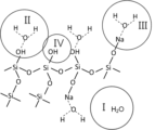
- FIG. 1 is a schematic diagram showing the state of water molecules present in sodium silicate.
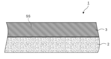
- FIG. 2 is a cross-sectional view showing a schematic diagram of an embodiment of the fire spread prevention material.
- FIG. 3 is a cross-sectional view showing a schematic diagram of an embodiment of the fire spread prevention material.
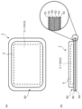
- Fig. 4(a) is a plan view showing an embodiment of a fire spread prevention material having an exterior body
- Fig. 4(b) is a side view showing an embodiment of a fire spread prevention material having an exterior body and an enlarged view showing a cross section of an end portion.
- FIG. 5 is a graph showing the change in moisture content (decrease rate) of sodium silicate with temperature change.
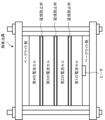
- FIG. 6 is a schematic diagram showing the configuration of a battery cell assembly for a simulated combustion test.
- Fig. 1 is a schematic diagram showing the state of water molecules present in sodium silicate
- Fig. 2 and Fig. 3 are cross-sectional views each showing a typical embodiment of a fire prevention material.
- the fire spread prevention material of the present invention is used by being disposed between two adjacent battery cells of a battery pack having two or more battery cells.
- the fire prevention material is required to have heat insulating properties (fire prevention properties) that suppress heat transfer to adjacent battery cells in the event of an abnormality.
- the fire spread prevention material of the present invention includes an inorganic fiber substrate containing inorganic fibers and sodium silicate supported on the inorganic fiber substrate.
- the sodium silicate has a moisture content of 15% by mass or more and 35% by mass or less at 100° C.
- the sodium silicate is a compound represented by Na 2 O.nSiO 2.mH 2 O (m is 0 or a positive number).
- sodium silicate contains sufficient moisture even at 100° C., so that in an emergency, the latent heat of vaporization of moisture provides good insulation (insulation effect). Therefore, even if one battery cell were to catch fire in an emergency, the spread of fire to adjacent battery cells can be prevented or delayed.
- the fire spread prevention property of a fire spread prevention material can be evaluated by heating one side of the fire spread prevention material at 650°C for 120 seconds and measuring the surface temperature of the other side of the fire spread prevention material (surface temperature after 120 seconds have passed).
- the surface temperature of the other side of the fire spread prevention material after 120 seconds is preferably about 150° C. or less, more preferably about 140° C. or less, and even more preferably about 120° C. or less.
- the lower limit of the surface temperature is, for example, about 25° C. If the fire spread prevention material exhibits a surface temperature in the above range, it can be determined that the fire spread prevention property is excellent.
- the surface temperature can be measured by the method described in the Examples.
- the fire spread prevention material has flexibility that can follow the expansion and contraction of the battery cells.
- an inorganic fiber base material carrying sodium silicate with, for example, a polyurethane sheet material, it is possible to impart good flexibility to the fire spread prevention material. This allows the fire spread prevention material to follow the expansion and contraction of the battery cells, reducing the mechanical load on the battery cells, and as a result, the assembled battery can repeatedly operate (charge and discharge) stably.
- sodium silicate contains a larger amount of moisture at temperatures below 100° C. Therefore, the fire prevention material can maintain high flexibility during production of the fire prevention material, storage of the fire prevention material, production of the assembled battery, etc. As a result, the productivity of the fire prevention material and the assembled battery can be improved.
- the moisture content of sodium silicate at 100°C may be about 15% by mass or more and 35% by mass or less, preferably about 18% by mass or more and 32% by mass or less, and more preferably about 21% by mass or more and 29% by mass or less. In this case, the above-mentioned effect of the fire spread prevention material can be further improved.
- the moisture content (moisture content change) of sodium silicate can be measured (obtained) by the method described in the examples.
- the rate of decrease in moisture content of sodium silicate from 30° C. to 100° C. is preferably about 0.75% by mass/° C. or less, more preferably about 0.65% by mass/° C. or less, and even more preferably about 0.55% by mass/° C. or less.
- the fire spread prevention material contains sufficient moisture in the temperature range of 30° C. to 100° C., which can contribute to improving the productivity of the fire spread prevention material and the battery pack, and to stable operation of the battery pack.
- the rate of decrease in moisture content can be calculated by the following formula 1.
- Moisture content reduction rate (mass%/°C) ([moisture content of sodium silicate at 30°C] - [moisture content of sodium silicate at 100°C]) / [moisture content of sodium silicate at 30°C] x 100
- the state of water molecules present in sodium silicate is classified as follows: I: free water, II: water molecules hydrogen-bonded with OH, III: water molecules adsorbed to Na, and IV: water molecules present as OH, as shown in Figure 1.
- the order of evaporation of water molecules is thought to be I ⁇ II ⁇ III ⁇ IV (however, evaporation may occur simultaneously).
- it is preferable to increase the ratio of Na2O contained in sodium silicate i.e., to decrease the SiO2 / Na2O molar ratio).
- the SiO2 / Na2O molar ratio is preferably about 3.7 or less, more preferably about 1 to 3.5, even more preferably about 1.5 to 3, and particularly preferably 2 to 2.3.
- the fire spread prevention property of the fire spread prevention material is further improved, and the productivity of the fire spread prevention material and the battery pack can also be further increased.
- the ratio of sodium silicate to the total of sodium silicate and the inorganic fiber substrate is preferably about 60% by mass or more and about 98% by mass or less, more preferably about 70% by mass or more and about 95% by mass or less, and even more preferably about 75% by mass or more and about 90% by mass or less. In this case, it is easy to impart superior fire spread prevention properties to the fire spread prevention material, and the weight of the fire spread prevention material can also be reduced.
- the ratio of the inorganic fiber base material to the total of sodium silicate and the inorganic fiber base material is preferably about 1% by mass to 40% by mass, more preferably about 1% by mass to 35% by mass, even more preferably about 5% by mass to 35% by mass, particularly preferably about 8% by mass to 30% by mass, and most preferably about 10% by mass to 20% by mass. In this case, it is easy to impart better fire spread prevention properties to the fire spread prevention material.
- the inorganic fiber substrate is a substrate (e.g., a sheet) composed primarily of inorganic fibers.
- a substrate e.g., a sheet
- multiple gaps (pores) are formed between the inorganic fibers.
- the inorganic fiber substrate has a porous structure.
- a layer containing sodium silicate can be unevenly distributed on one side of the inorganic fiber substrate by preparing a relatively highly viscous aqueous solution of sodium silicate, applying it to one side of the inorganic fiber substrate, and then drying it.
- a relatively low-viscosity aqueous solution of sodium silicate can be prepared, impregnated into the inorganic fiber substrate, and then dried to fill the voids in the inorganic fiber substrate with sodium silicate.
- inorganic fibers are fibrous substances having a length of about 1 mm or more and an aspect ratio (length/width) of about 100 or more.
- the length (fiber length) of the inorganic fibers is preferably about 3 mm or more and 12 mm or less.
- the width (fiber diameter) of the inorganic fibers is preferably about 3 ⁇ m or more and 10 ⁇ m or less.
- the average fiber diameter of the inorganic fibers is preferably about 5 ⁇ m or more and 10 ⁇ m.
- the average fiber diameter is a value measured by microscope observation such as a scanning electron microscope (SEM) or an optical microscope.
- the inorganic fiber substrate may be made of one type or a plurality of types of inorganic fibers.
- the constituent material of the inorganic fiber constituting the inorganic fiber substrate include silica (SiO 2 ), alumina (Al 2 O 3 ), carbon, silicon carbide (SiC), etc.
- the constituent material of the inorganic fiber preferably contains at least one selected from the group consisting of silica (SiO 2 ) and alumina (Al 2 O 3 ).
- the fire spread prevention material can be imparted with higher fire spread prevention properties, and the inorganic fiber substrate tends to have excellent shape processability before drying in the manufacturing process.
- inorganic fibers examples include glass fibers, silica fibers, alumina-silica fibers, alumina fibers, basalt fibers, rock wool, etc.
- the inorganic fiber substrate contains at least one of glass fibers, silica fibers, and alumina-silica fibers. In this case, the above-mentioned effects can be further improved.
- the content of inorganic fibers in the inorganic fiber substrate is preferably about 60% by mass or more and 100% by mass or less, more preferably about 70% by mass or more and 98% by mass or less, even more preferably about 80% by mass or more and 95% by mass or less, and particularly preferably about 85% by mass or more and 93% by mass or less.
- the fire spread prevention material can impart excellent fire spread prevention properties.
- the inorganic fiber substrate may further contain an organic binder.
- the organic binder is, for example, an organic material that bonds the inorganic fibers together, and one type of organic binder may be used alone, or multiple types may be used in combination.
- the organic binder for example, a resin having a glass transition point of room temperature (e.g., 25° C.) or lower, a water-soluble resin, etc.
- the organic binder include, for example, an acrylic resin, a polyvinyl alcohol resin (such as Vinylon), an epoxy resin, cellulose such as cellulose microfibril, a polyvinyl chloride resin, etc.
- the acrylic resin is a polymer containing at least one monomer unit selected from the group consisting of acrylic acid and its derivatives (such as acrylic acid esters), and methacrylic acid and its derivatives (such as methacrylic acid esters).
- the cellulose microfibril refers to microfibrillated cellulose fibers.
- the organic binder preferably contains at least one selected from the group consisting of an acrylic resin, a polyvinyl alcohol resin, and an epoxy resin. In this case, a fire prevention material having higher fire spread prevention properties tends to be obtained.
- the content of the organic binder in the inorganic fiber substrate is preferably about 0% by mass or more and about 40% by mass or less, more preferably about 2% by mass or more and about 30% by mass or less, even more preferably about 5% by mass or more and about 20% by mass or less, and particularly preferably about 7% by mass or more and about 15% by mass or less. In this case, a fire prevention material having better fire spread prevention properties is easily obtained.
- the inorganic fiber substrate may further contain inorganic particles, such as silica, aluminum hydroxide, zinc oxide, magnesium carbonate, and aluminum silicate.
- examples of particles containing silica include precipitated silica, fumed silica, colloidal silica, etc.
- precipitated silica is amorphous silica particles obtained by a precipitation method, which is a type of wet method, and has a porous structure.
- the average particle size of the inorganic particles is preferably about 0.1 ⁇ m or more and 100 ⁇ m or less, more preferably about 0.5 ⁇ m or more and 80 ⁇ m or less, and even more preferably about 1 ⁇ m or more and 50 ⁇ m or less.
- the average particle size of the inorganic particles is the value of the volume cumulative particle size D50 measured by a laser diffraction type particle size measuring device.
- Inorganic particles having such an average particle size are easy to handle and can be more uniformly distributed in the inorganic fiber substrate.
- the content of inorganic particles in the inorganic fiber substrate is preferably about 20% by mass or more and 50% by mass or less, more preferably about 25% by mass or more and 45% by mass or less, and even more preferably about 30% by mass or more and 40% by mass or less.
- inorganic particles By containing inorganic particles at such a content, heat insulation is improved and a fire prevention material having better fire prevention properties can be obtained.
- an inorganic fiber substrate (and thus a fire prevention material) that is lighter and has higher mechanical strength. From the viewpoint of increasing the mechanical strength of the inorganic fiber substrate, it is preferable that the inorganic fiber substrate does not contain precipitated silica, and it is more preferable that the inorganic fiber substrate does not contain inorganic particles.
- the inorganic fiber substrate may contain a flocculant such as a polyamidine polymer.
- the content of the flocculant in the inorganic fiber substrate is preferably about 0.1% by mass or more and about 5% by mass or less, more preferably about 0.3% by mass or more and about 4% by mass or less, and even more preferably about 0.5% by mass or more and about 3% by mass or less.
- the inorganic fiber substrate may contain sodium silicate (sodium silicate other than sodium silicate having a moisture content at 100° C. of 15% by mass or more and 35% by mass or less), or may not contain such sodium silicate. When such sodium silicate is contained, the content of sodium silicate in the inorganic fiber substrate is preferably about 10 mass % or less, more preferably about 5 mass % or less, and even more preferably about 3 mass % or less.
- the inorganic fiber substrate for example, a substrate having excellent retention (support) of sodium silicate is preferably used.
- the inorganic fiber substrate is preferably a nonwoven fabric, more preferably a sheet (wet-formed sheet) formed by a wet-formed sheeting method.
- the wet-formed sheet is preferable from the viewpoint of being particularly excellent in retention of sodium silicate.
- materials inorganic fibers, organic binders, etc.
- This method makes it easy to obtain an inorganic fiber substrate (nonwoven fabric) having substantially uniformly distributed voids.
- the apparent density of the inorganic fiber substrate is preferably about 0.08 g/cm 3 or more and 0.2 g/cm 3 or less.
- the basis weight of the inorganic fiber substrate is preferably about 100 g/m 2 or less and 170 g/m 2 or less when the thickness is 1 mm.
- the thickness of the inorganic fiber substrate is preferably 0.2 mm or more and 3 mm or less.
- the sodium silicate may be unevenly distributed on one side of the inorganic fiber substrate, or may be impregnated into the inorganic fiber substrate. That is, the fire spread prevention material 1 may have a two-layer structure of an inorganic fiber substrate 2 and a layer 3 containing sodium silicate SS as shown in Fig. 2, or may have a single-layer structure in which the inorganic fiber substrate 2 is impregnated with sodium silicate SS as shown in Fig. 3.
- the sodium silicate SS unevenly distributed or impregnated in the inorganic fiber substrate 2 may be in a liquid state or a gel state, but is preferably in a gel state.
- the gel-like sodium silicate SS is easily supported on the inorganic fiber substrate 2, and is therefore unlikely to fall off from the inorganic fiber substrate 2 during the manufacture of the fire spread prevention material 1.
- the two-layer fire spread prevention material 1 can be formed, for example, by preparing an aqueous solution of sodium silicate SS with a relatively high viscosity, applying it to one side of the inorganic fiber substrate 2, and then drying it to form a layer 3 containing sodium silicate SS unevenly distributed on one side of the inorganic fiber substrate 2.
- a gravure coating method, a slot die coating method, a knife coating method, a blade coating method, a comma coating method, a reverse roll coating method, an inkjet method, or the like is suitably used.
- a single-layer fire spread prevention material 1 can be produced, for example, by preparing an aqueous solution of sodium silicate SS with a relatively low viscosity, impregnating it into an inorganic fiber substrate 2, pressurizing it if necessary, and then drying it, thereby filling the voids in the inorganic fiber substrate 2 with sodium silicate SS.
- Any of the above fire spread prevention materials 1 are suitably manufactured by a roll-to-roll process in which the inorganic fiber substrate 2 wound into a roll is sent out, an aqueous solution of sodium silicate SS is supplied thereto, the aqueous solution is dried, and the fire spread prevention material 1 is wound into a roll.
- the fire spread prevention material 1 can maintain high flexibility even during the manufacture of the fire spread prevention material 1. Therefore, the operation of winding the fire spread prevention material 1 into a roll can be performed smoothly, and cracks, etc. are unlikely to occur in the fire spread prevention material 1 even after it is wound into a roll.
- the layer 3 and in the configuration example of Fig. 3, the fire spread prevention material 1 preferably absorb heat in the temperature range of 100° C. to 300° C.
- the mass reduction rate when the sodium silicate-containing portion is heated from 100° C. to 300° C. at a rate of 50° C./min is 15% by mass or more.
- the endothermic reaction of the sodium silicate-containing portion is believed to occur when moisture in the sodium silicate-containing portion (e.g., water molecules in sodium silicate) undergoes an endothermic reaction in the temperature range of 100° C. to 300° C.
- the mass loss of the sodium silicate-containing portion is believed to occur due to this endothermic reaction. Therefore, the mass reduction rate when the sodium silicate-containing portion is heated from 100° C. to 300° C. at 50° C./min correlates with the moisture content and heat absorption amount contained in the sodium silicate-containing portion. For this reason, it is presumed that when the mass reduction rate of the sodium silicate-containing portion is 15% by mass or more, the heat absorption amount in the above temperature range becomes large, and sufficient fire spread prevention properties are obtained in the fire spread prevention material.
- the endothermic heat of the sodium silicate-containing portion can be confirmed, for example, by performing thermogravimetry-differential thermal analysis (TG-DTA) measurement and checking the presence or absence of an endothermic peak within a temperature range of 100° C. or higher and 300° C. or lower.
- TG-DTA thermogravimetry-differential thermal analysis
- the mass reduction rate when the sodium silicate-containing portion is heated from 100°C to 300°C at 50°C/min is preferably about 15% by mass or more and 30% by mass or less, more preferably about 17% by mass or more and 28% by mass or less, even more preferably about 20% by mass or more and 25% by mass or less, particularly preferably about 23% by mass or more and 25% by mass or less, and most preferably about 23.5% by mass or more and 25% by mass or less.
- a fire spread prevention material having better fire spread prevention properties is easily obtained.
- the mass reduction rate can be calculated by the following formula 2.
- Mass reduction rate (mass%) [mass reduction amount of sodium silicate-containing part] / [mass of sodium silicate-containing part at 100 ° C.] ⁇ 100
- the mass loss of the sodium silicate-containing portion is the difference between the mass of the sodium silicate-containing portion at 100° C. and the mass of the sodium silicate-containing portion at 300° C.
- the mass loss rate of each sodium silicate-containing portion may be in the above range, and the total mass loss rate of all the sodium silicate-containing portions may be in the above range.
- the fire spread prevention material is preferably insulating.
- the fire spread prevention material can be given high insulating properties.
- having insulating properties means that the electrical resistivity measured by volume resistivity measurement is 10 8 ⁇ cm or more.
- the fire spread prevention material may be in a sheet form (for example, a flat plate form) or may be processed into a predetermined shape. The predetermined shape may be appropriately set depending on the shape of the installation location of the fire spread prevention material.
- the predetermined shape may be, for example, a shape that conforms to the shape of the installation location of the fire spread prevention material (such as the surface shape of the component that is placed opposite the fire spread prevention material).
- Specific examples of the shape include a sheet shape with unevenness on the surface, a sheet shape with a curved portion at an angle of 90° or more, etc.
- the shape of the unevenness is not particularly limited, and may be a rectangular cross-section, a V-shaped cross-section, a U-shaped cross-section, etc.
- the fire spread prevention material processed into a predetermined shape can be manufactured by the manufacturing method described below, thereby preventing the inorganic fiber substrate and the sodium silicate from being separated or broken. The absence of separation or breakage in the fire spread prevention material can be confirmed, for example, by observing the cross section of the fire spread prevention material with a scanning electron microscope (SEM).
- a fire prevention material that has been processed into a predetermined shape can maintain that shape.
- the ability of a fire prevention material to maintain a predetermined shape can be quantified by the three-point bending strength of the fire prevention material.
- the three-point bending strength of the fire spread prevention material measured according to JIS K 7171 is preferably about 0.5 MPa to 5 MPa, more preferably about 0.8 MPa to 4 MPa, and even more preferably about 1 MPa to 3 MPa. It can be said that a fire spread prevention material with such a three-point bending strength has sufficient strength to maintain a predetermined shape.
- the total thickness of the inorganic fiber substrate and sodium silicate thickness of the fire spread prevention material 1 in the configuration examples of Figs.
- a fire spread prevention material with higher fire spread prevention properties can be obtained, and the arrangement space for the fire spread prevention material in the battery pack can be prevented from becoming large.
- the fire spread prevention material 1 may further include an exterior body 5 that contains the inorganic fiber substrate 2 and sodium silicate SS.
- the fire spread prevention material 1 includes a fire spread prevention material main body, which is the inorganic fiber substrate 2 carrying sodium silicate SS, and an exterior body 5 that contains this fire spread prevention material main body.
- the amount of moisture dissipated from the fire spread prevention material 1 can be adjusted (reduced).
- Fig. 4(a) is a plan view showing an embodiment of a fire spread prevention material having an exterior body, and Fig.
- the water vapor transmission rate of the exterior body 5 at 40°C and 90% RH is preferably about 15 g/ m2 /day or less, more preferably about 10 g/ m2 /day or less, even more preferably about 5 g/ m2 /day or less, and particularly preferably about 1 g/ m2 /day or less.
- the lower limit of the water vapor transmission rate of the exterior body at 40°C is about 0.01 g/ m2 /day.
- the water vapor permeability (water vapor permeability) is measured by a method according to JIS K 7129-2:2019.
- the exterior body 5 contains a composite of the inorganic fiber substrate 2 and sodium silicate SS inside by sealing the outer peripheries of the two sheet materials 5a, 5b with a seal portion 50.
- the seal portion 50 is formed by joining the outer peripheries of the two sheet materials 5a, 5b by a method such as fusion (ultrasonic fusion, high-frequency fusion, heat fusion). Note that it is also possible to fold one sheet material in half and seal the outer periphery with a seal portion to contain a composite of the inorganic fiber substrate 2 and sodium silicate SS inside.
- each sheet material 5a, 5b is a laminate having a base layer 51, a sealing layer 52 provided on the inner surface side of the base layer 51, and a protective layer 53 provided on the outer surface side of the base layer 51.
- the base layer 51 has a function of imparting mechanical strength to the sheet materials 5a and 5b, and a function of adjusting (blocking) the transmission of moisture (water vapor).
- the base layer 51 may be made of a metal foil. Examples of materials for the metal foil include aluminum or an aluminum alloy, nickel or a nickel alloy, and stainless steel.
- the thickness of the base layer 51 is not particularly limited, but is preferably about 5 ⁇ m to 100 ⁇ m, more preferably about 8 ⁇ m to 80 ⁇ m, and even more preferably about 12 ⁇ m to 60 ⁇ m, in which case the sheet materials 5 a, 5 b can have an appropriate water vapor permeability and sufficient flexibility.
- the sealing layer 52 has a function of sealing the exterior body 5 by being fused.
- the constituent material (fusible material) of the sealing layer 52 include polyethylene (LDPE, LLPDE), polypropylene, ethylene-vinyl acetate copolymer, polyethylene terephthalate, polybutylene terephthalate, polyvinyl chloride, polyvinylidene chloride, ethylene-vinyl alcohol copolymer, polystyrene, polyacrylonitrile, ethylene-(meth)acrylic acid copolymer, polymethylpentene, etc.
- polypropylene is more preferable, and non-oriented polypropylene is even more preferable.
- the thickness of the sealing layer 52 is not particularly limited, but is preferably about 5 ⁇ m to 200 ⁇ m, more preferably about 10 ⁇ m to 100 ⁇ m, even more preferably about 20 ⁇ m to 120 ⁇ m, and particularly preferably about 30 ⁇ m to 80 ⁇ m. This makes it possible to improve the sealing property while ensuring the flexibility of each of the sheet materials 5 a and 5 b.
- the protective layer 53 has a function of protecting the base material layer 51 (preventing corrosion, etc., of the base material layer 51 ).
- a relatively hard resin material is used as the constituent material of the protective layer 53.
- hard resin materials include polyamide resins (nylon), acrylic resins, polyimide resins, polyetherimide resins, polysulfone resins, polyethersulfone resins, polyetheretherketone resins, polycarbonate resins, polyvinyl butyral resins, polyarylate resins, fluorine resins, and polyester resins.
- the thickness of the protective layer 53 is not particularly limited, but is preferably about 5 ⁇ m to 100 ⁇ m, more preferably about 10 ⁇ m to 50 ⁇ m, and even more preferably about 15 ⁇ m to 30 ⁇ m.
- the thickness of the exterior body is not particularly limited, but is preferably about 250 ⁇ m or less, more preferably about 200 ⁇ m or less, and even more preferably about 100 ⁇ m or less. In this case, it becomes easier to set the water vapor transmission rate of the exterior body 5 within the above range. As a result, the amount of moisture dissipated from the fire spread prevention material 1 can be suitably adjusted (reduced), and thus the fire spread prevention property is further improved.
- the sheet materials 5a and 5b are not limited to a three-layer structure, and may be a single-layer (one-layer) structure, a two-layer structure, or a four-layer or more structure depending on the required characteristics.
- the fire spread prevention material of the present invention is not limited to the above embodiment.
- a battery pack including two or more battery cells and the above-mentioned fire prevention material disposed between adjacent battery cells.
- the battery pack is, for example, a lithium ion battery.
- an automobile including an automobile body and the above-described battery pack mounted in the automobile body. Furthermore, it may be provided in the following aspects:
- a fire spread prevention material comprising an inorganic fiber substrate containing inorganic fibers and sodium silicate supported on the inorganic fiber substrate, the sodium silicate having a moisture content of 15% by mass or more and 35% by mass or less at 100°C.
- a fire prevention material according to any one of (1) to (4) above, in which the sodium silicate is unevenly distributed on one side of the inorganic fiber substrate or is impregnated into the inorganic fiber substrate.
- a fire prevention material according to any one of (1) to (8) above, which is used by being placed between two adjacent battery cells of a battery pack having two or more battery cells.
- FIG. 5 is a graph showing the change in moisture content (decrease rate) of sodium silicate with temperature change.
- Sodium silicate SS1 had a moisture content of 55% by mass at 30°C and 26% by mass at 100°C, and the rate of decrease in moisture content from 30°C to 100°C was 0.53% by mass/°C.
- Sodium silicate SS2 had a moisture content of 61% by mass at 30°C and 19% by mass at 100°C, and the rate of decrease in moisture content from 30°C to 100°C was 0.69% by mass/°C.
- Sodium silicate SS3 had a moisture content of 61% by mass at 30°C and 13% by mass at 100°C, and the rate of decrease in moisture content from 30°C to 100°C was 0.79% by mass/°C.
- the order of the magnitude relationship of the moisture content of sodium silicate SS1, sodium silicate SS2 and sodium silicate SS3 was reversed between 30°C and 100°C.
- inorganic fiber substrate 6.5 parts by mass of inorganic fiber F1 and 0.7 parts by mass of organic binder B1 were added to 100 parts by mass of pure water, and mixed for 2 hours with a homomixer manufactured by Tokushu Kika Kogyo Co., Ltd. to obtain a dispersion.
- This dispersion was formed into a papermaking screen and dried with a Yankee dryer to prepare wet-formed sheets (nonwoven fabric) A and wet-formed sheets (nonwoven fabric) B of different thicknesses.
- the wet-formed sheet A had a thickness of 1.5 mm and a basis weight of 73 g/ m2 .
- the wet-formed sheet B had thicknesses of 1.5 mm, 2 mm, and 3 mm and a basis weight of 120 g/ m2 .
- Example 1 An aqueous solution of sodium silicate SS1 prepared to a predetermined solid content was applied to the upper surface of the wet-formed sheet (inorganic fiber substrate) A by a slot die coating method, and then dried at 30° C. In this way, a fire spread prevention material (total thickness: 3 mm) having a two-layer structure including the wet-formed sheet and an upper layer containing sodium silicate SS1 was produced.
- Example 2 A two-layer fire prevention material was prepared in the same manner as in Example 1, except that sodium silicate SS1 was changed to sodium silicate SS2.
- Comparative Example 1 A two-layer fire prevention material was prepared in the same manner as in Example 1, except that sodium silicate SS1 was changed to sodium silicate SS3.
- Example 3 The aqueous solution of sodium silicate SS1 prepared to a predetermined solid content was impregnated into a wet-formed sheet (inorganic fiber substrate) B, compressed with a roller, and then dried at 30° C. In this way, a one-layer fire spread prevention material (total thickness: 1.5 mm, 2 mm, and 3 mm) in which sodium silicate SS1 was filled in the voids of the wet-formed sheet was produced.
- Example 4 A one-layer fire prevention material was prepared in the same manner as in Example 3, except that sodium silicate SS1 was changed to sodium silicate SS2. (Comparative Example 2) A one-layer fire prevention material was prepared in the same manner as in Example 3, except that sodium silicate SS1 was changed to sodium silicate SS3.
- A The back surface temperature of the fire prevention material was 150°C or lower.
- B The back surface temperature of the fire prevention material was higher than 150°C and lower than 190°C.
- C The back surface temperature of the fire prevention material was higher than 190°C.
- Example 3 Each of the fire spread prevention materials (thickness 3 mm) of Example 3, Example 4, and Comparative Example 2 was sandwiched between two exterior sheets (manufactured by Toppan Printing Co., Ltd., "GX-P-F", thickness 200 ⁇ m, water vapor transmission rate 0.05 g/m 2 /day (40°C, 90% RH)) and the outer periphery was sealed to prepare an exterior body.
- a fire spread prevention material equipped with an exterior body was obtained.
- the fire spread prevention property of this fire spread prevention material equipped with an exterior body was evaluated according to the method described in "5-2. Evaluation of fire spread prevention property". The results are shown in Table 3 below.
- FIG. 6 is a schematic diagram showing the configuration of a battery cell assembly for a simulated combustion test.
- Test Example 1 four battery cells ("laminated type", "capacity approximately 80 Ah") were prepared. The size of each battery cell was 545 mm in total length, 98 mm in width, 9 mm in thickness, and the weight was 1.1 kg. One sheet of the fire spread prevention material (thickness 1 mm) of Example 3 was placed between each pair of adjacent battery cells. In other words, the battery cell spacing was 1 mm. With Bakelite plates placed above and below this laminate, it was fixed with a restraining jig. In this way, a battery cell assembly was produced. A heater was provided on the lower Bakelite plate so as to come into contact with the first battery cell.
- Test Example 2 A battery cell assembly was fabricated in the same manner as in Test Example 1, except for the following changes.
- One fire spread prevention material (thickness 1.5 mm) of Example 3 was placed between the first battery cell and the second battery cell, one fire spread prevention material (thickness 1.5 mm) of Example 3 was placed between the second battery cell and the third battery cell, and one fire spread prevention material (thickness 2 mm) of Example 3 was placed between the third battery cell and the fourth battery cell. That is, the battery cell intervals from the bottom were 1.5 mm, 1.5 mm, and 2 mm, respectively.
- a battery cell assembly was produced in the same manner as in Test Example 1, except that nothing was placed between the first battery cell and the second battery cell, and an alumina fiber base material having a thickness of 1 mm ("Arsen Paper” manufactured by Denka Company Ltd.) was placed between the second battery cell and the third battery cell, and between the third battery cell and the fourth battery cell.
- 1 Fire prevention material
- 2 Inorganic fiber base material
- 3 Layer
- 5 Exterior body
- 5a Sheet material
- 5b Sheet material
- 50 Sealing part
- 51 Base material layer
- 52 Sealing layer
- 53 Protective layer
- SS Sodium silicate
Landscapes
- Chemical & Material Sciences (AREA)
- Life Sciences & Earth Sciences (AREA)
- Chemical Kinetics & Catalysis (AREA)
- General Chemical & Material Sciences (AREA)
- Engineering & Computer Science (AREA)
- Geochemistry & Mineralogy (AREA)
- Materials Engineering (AREA)
- Organic Chemistry (AREA)
- General Life Sciences & Earth Sciences (AREA)
- Electrochemistry (AREA)
- Inorganic Chemistry (AREA)
- Manufacturing & Machinery (AREA)
- Battery Mounting, Suspending (AREA)
- Secondary Cells (AREA)
- Surface Treatment Of Glass Fibres Or Filaments (AREA)
- Laminated Bodies (AREA)
Priority Applications (1)
| Application Number | Priority Date | Filing Date | Title |
|---|---|---|---|
| EP24849083.1A EP4755858A1 (en) | 2023-07-28 | 2024-07-26 | Fire spread prevention material, battery pack, and automobile |
Applications Claiming Priority (2)
| Application Number | Priority Date | Filing Date | Title |
|---|---|---|---|
| JP2023-123559 | 2023-07-28 | ||
| JP2023123559A JP7499390B1 (ja) | 2023-07-28 | 2023-07-28 | 延焼防止材、組電池及び自動車 |
Publications (1)
| Publication Number | Publication Date |
|---|---|
| WO2025028430A1 true WO2025028430A1 (ja) | 2025-02-06 |
Family
ID=91377615
Family Applications (1)
| Application Number | Title | Priority Date | Filing Date |
|---|---|---|---|
| PCT/JP2024/026768 Ceased WO2025028430A1 (ja) | 2023-07-28 | 2024-07-26 | 延焼防止材、組電池及び自動車 |
Country Status (3)
| Country | Link |
|---|---|
| EP (1) | EP4755858A1 (cg-RX-API-DMAC7.html) |
| JP (3) | JP7499390B1 (cg-RX-API-DMAC7.html) |
| WO (1) | WO2025028430A1 (cg-RX-API-DMAC7.html) |
Families Citing this family (2)
| Publication number | Priority date | Publication date | Assignee | Title |
|---|---|---|---|---|
| CN122459956A (zh) * | 2023-12-26 | 2026-07-24 | 电化株式会社 | 延烧防止材、电池组及汽车 |
| WO2026023563A1 (ja) * | 2024-07-23 | 2026-01-29 | デンカ株式会社 | 延焼防止材、組電池及び自動車 |
Citations (2)
| Publication number | Priority date | Publication date | Assignee | Title |
|---|---|---|---|---|
| JP2010053196A (ja) | 2008-08-27 | 2010-03-11 | Asahi Kasei E-Materials Corp | 吸熱シート |
| WO2022270359A1 (ja) * | 2021-06-24 | 2022-12-29 | デンカ株式会社 | 延焼防止材、組電池及び自動車 |
Family Cites Families (2)
| Publication number | Priority date | Publication date | Assignee | Title |
|---|---|---|---|---|
| JP2010228960A (ja) | 2009-03-27 | 2010-10-14 | Aica Kogyo Co Ltd | スラリー及びプリプレグ並びに不燃基材 |
| AT523824B1 (de) | 2020-06-10 | 2021-12-15 | Eine Illarion | Brandschutzsystem |
-
2023
- 2023-07-28 JP JP2023123559A patent/JP7499390B1/ja active Active
-
2024
- 2024-06-03 JP JP2024089650A patent/JP7637300B2/ja active Active
- 2024-07-26 EP EP24849083.1A patent/EP4755858A1/en active Pending
- 2024-07-26 WO PCT/JP2024/026768 patent/WO2025028430A1/ja not_active Ceased
-
2025
- 2025-02-14 JP JP2025022552A patent/JP2025068008A/ja active Pending
Patent Citations (2)
| Publication number | Priority date | Publication date | Assignee | Title |
|---|---|---|---|---|
| JP2010053196A (ja) | 2008-08-27 | 2010-03-11 | Asahi Kasei E-Materials Corp | 吸熱シート |
| WO2022270359A1 (ja) * | 2021-06-24 | 2022-12-29 | デンカ株式会社 | 延焼防止材、組電池及び自動車 |
Non-Patent Citations (1)
| Title |
|---|
| OTAKA TAKESHI, ASAKO YUTAKA: "Heat Protection Characteristics of Fire Protection Materials of High Water Content Using Sodium Silicate", BULLETIN OF JAPAN ASSOCIATION FOR FIRE SCIENCE AND ENGINEERING, JAPAN ASSOCIATION FOR FIRE SCIENCE AND ENGINEERING, vol. 56, no. 1, 1 January 2006 (2006-01-01), pages 9 - 14, XP093270449, ISSN: 0546-0794, DOI: 10.11196/kasai.56.1_9 * |
Also Published As
| Publication number | Publication date |
|---|---|
| JP2025019759A (ja) | 2025-02-07 |
| EP4755858A1 (en) | 2026-06-10 |
| JP2025019997A (ja) | 2025-02-07 |
| JP7637300B2 (ja) | 2025-02-27 |
| JP2025068008A (ja) | 2025-04-24 |
| JP7499390B1 (ja) | 2024-06-13 |
Similar Documents
| Publication | Publication Date | Title |
|---|---|---|
| JP7637300B2 (ja) | 延焼防止材、組電池及び自動車 | |
| CN113875082A (zh) | 用于高安全性包设计的导热性各向异性的多层复合材料 | |
| CN112151918B (zh) | 一种隔热膜及其制备方法与应用 | |
| US12521961B2 (en) | Thermal insulation material | |
| JP7009892B2 (ja) | 蓄電モジュール及び蓄電パック | |
| JP7533183B2 (ja) | シート状耐熱材の製造方法および積層体 | |
| CN113811638A (zh) | 用于单电池的具有隔热层的壳体 | |
| WO2022270359A1 (ja) | 延焼防止材、組電池及び自動車 | |
| US20240250334A1 (en) | Thermal runaway suppression sheet and battery pack and/or battery module using the same | |
| JP2024103675A (ja) | シート状耐熱材および積層体 | |
| US20240278531A1 (en) | Fire spread prevention material, method for producing same, laminate, assembled battery, and automobile | |
| JP7772582B2 (ja) | 電池用保護シート及び組電池モジュール | |
| JP2023118245A (ja) | 熱暴走抑制シート及びこれを用いた組電池 | |
| WO2025142352A1 (ja) | 延焼防止材、組電池及び自動車 | |
| JP2023056748A (ja) | 熱伝達抑制シート、熱伝達抑制シートの製造方法及び組電池 | |
| JP7533182B2 (ja) | シート状耐熱材の製造方法および積層体 | |
| JP2022125585A (ja) | 断熱材 | |
| JP7400070B1 (ja) | 延焼防止材、積層体、組電池及び自動車 | |
| JP7832051B2 (ja) | バスバー及び蓄電装置 | |
| WO2022234746A1 (ja) | 無機粉体シート及びその製造方法 | |
| JP7831226B2 (ja) | 断熱シート、組電池 | |
| WO2025197842A1 (ja) | 延焼防止材、組電池及び自動車 | |
| WO2026023563A1 (ja) | 延焼防止材、組電池及び自動車 | |
| JP7810583B2 (ja) | 防炎構造体の製造方法 | |
| CN118738748A (zh) | 包括耐火性和热扩散性改进型复合云母绝缘垫的电池模块 |
Legal Events
| Date | Code | Title | Description |
|---|---|---|---|
| 121 | Ep: the epo has been informed by wipo that ep was designated in this application |
Ref document number: 24849083 Country of ref document: EP Kind code of ref document: A1 |
|
| WWE | Wipo information: entry into national phase |
Ref document number: 2024849083 Country of ref document: EP |
|
| NENP | Non-entry into the national phase |
Ref country code: DE |