WO2025028362A1 - 冷凍装置及び制御方法 - Google Patents
冷凍装置及び制御方法 Download PDFInfo
- Publication number
- WO2025028362A1 WO2025028362A1 PCT/JP2024/026467 JP2024026467W WO2025028362A1 WO 2025028362 A1 WO2025028362 A1 WO 2025028362A1 JP 2024026467 W JP2024026467 W JP 2024026467W WO 2025028362 A1 WO2025028362 A1 WO 2025028362A1
- Authority
- WO
- WIPO (PCT)
- Prior art keywords
- oil
- unit
- refrigeration
- pipe
- units
- Prior art date
- Legal status (The legal status is an assumption and is not a legal conclusion. Google has not performed a legal analysis and makes no representation as to the accuracy of the status listed.)
- Pending
Links
Images


Classifications
-
- F—MECHANICAL ENGINEERING; LIGHTING; HEATING; WEAPONS; BLASTING
- F25—REFRIGERATION OR COOLING; COMBINED HEATING AND REFRIGERATION SYSTEMS; HEAT PUMP SYSTEMS; MANUFACTURE OR STORAGE OF ICE; LIQUEFACTION SOLIDIFICATION OF GASES
- F25B—REFRIGERATION MACHINES, PLANTS OR SYSTEMS; COMBINED HEATING AND REFRIGERATION SYSTEMS; HEAT PUMP SYSTEMS
- F25B1/00—Compression machines, plants or systems with non-reversible cycle
Definitions
- This disclosure relates to a refrigeration device and a control method thereof.
- Patent Document 1 discloses a technology for combining and connecting multiple refrigerators, each of which has a compressor, oil separator, and condenser, to form a large-capacity multi-refrigeration system.
- Patent Document 2 discloses a refrigeration system incorporating multiple compressors and oil separators.
- the present disclosure aims to provide a refrigeration device equipped with multiple oil separators that can adjust the amount of oil contained in the multiple oil separators, and a control method thereof.
- the refrigeration device of the present disclosure includes N (N is an integer of 2 or more) refrigeration units each having a compressor, an oil separator, and an oil return pipe that returns oil separated from the refrigerant by the oil separator to the compressor; an oil supply pipe connecting the oil return pipes of the N refrigeration units; N oil supply valves that are arranged in the oil supply pipe between the oil return pipes of the adjacent refrigeration units and control the flow of oil in the oil supply pipe; and a control unit that, when it is determined that the amount of oil in the oil separator of at least one of the N refrigeration units is less than a predetermined threshold, opens all oil supply valves arranged in the oil supply pipe between the oil return pipe of at least one of the refrigeration units other than the refrigeration unit whose oil amount is determined to be less than the predetermined threshold and closes the other oil supply valves.
- the control method disclosed herein is a control method for a refrigeration system including N (N is an integer of 2 or more) refrigeration units each having a compressor, an oil separator, and an oil return pipe for returning oil separated from a refrigerant by the oil separator to the compressor, an oil supply pipe connecting the oil return pipes of the N refrigeration units, N oil supply valves arranged in the oil supply pipe between the oil return pipes of the adjacent refrigeration units and for controlling the flow of oil in the oil supply pipe, and a control unit, and further including: When it is determined that the oil amount in the oil separator of at least one of the refrigeration units is less than the predetermined threshold, and when it is determined that the oil amount in the oil separator of at least one of the N refrigeration units is less than the predetermined threshold, control is performed to open all the oil supply valves arranged in the oil supply pipe between the oil return pipe of at least one of the refrigeration units other than the refrigeration unit determined to have the oil amount less than the predetermined threshold and the oil return pipe of the refrigeration unit determined to have the oil amount less than the predetermined
- the amount of oil contained in the multiple oil separators can be adjusted.
- FIG. 1 is a diagram showing a schematic configuration of a refrigeration device according to an embodiment of the present disclosure.
- FIG. 1 is a diagram showing a schematic configuration of a refrigeration unit.
- Block diagram showing the control system of the refrigeration device FIG. 4 is a diagram for explaining a first control.
- FIG. 4 is a diagram for explaining a second control.
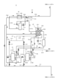
- Fig. 1 is a diagram showing a schematic configuration of a refrigeration device 1 according to an embodiment of the present disclosure.
- Fig. 2 is a diagram showing a schematic configuration of a refrigeration unit 20.
- the refrigeration device 1 includes four refrigeration units 20_1 to 20_4, a cooling unit 50, a connection unit 60, and a control unit 70.
- the four freezing units 20_1 to 20_4 are arranged in parallel in the refrigeration cycle. Note that, in this embodiment, an example in which the refrigeration device 1 is equipped with four freezing units 20_1 to 20_4 is described, but the refrigeration device of the present disclosure may be equipped with multiple (N) freezing units. In other words, the number of freezing units equipped in the refrigeration device may be two, three, five or more.
- one of the four freezer units will be referred to as 20_1, the freezer unit arranged adjacent to freezer unit 20_1 will be referred to as 20_2, the freezer unit arranged further adjacent to freezer unit 20_2 will be referred to as 20_3, and the freezer unit arranged further adjacent to freezer unit 20_3 will be referred to as 20_4.
- the four freezer units 20_1 to 20_4 each have the same configuration.
- the suffixes "_1", “_2", “_3”, and “_4" may be omitted.
- FIG. 2 which illustrates the configuration common to the four freezer units 20_1 to 20_4, the suffixes are omitted.
- the refrigeration unit 20 includes a compression section 21, a heat dissipation heat exchanger 22, an oil separator 23, a pressure reducing valve 41, an intermediate cooler 42, and a split heat exchanger 43.
- the refrigeration device 1 includes four pressure reducing valves, the same number as the refrigeration units.
- the compression section 21 includes a first compressor 211 and a second compressor 212.
- the first compressor 211 and the second compressor 212 are arranged in parallel in a refrigeration cycle.
- the compression section 21 may include one compressor or three or more compressors. When the compression section 21 includes three or more compressors, the three or more compressors are arranged in parallel in a refrigeration cycle. Since the first compressor 211 and the second compressor 212 have a similar configuration, the first compressor 211 will be described in detail and the second compressor 212 will be described briefly.
- the first compressor 211 has a sealed container.
- the sealed container is formed with a first low-stage suction port 211A, a first low-stage discharge port 211B, a first high-stage suction port 211C, and a first high-stage discharge port 211D.
- the first low-stage suction port 211A is connected to the evaporator of the cooling unit 50 via a pipe P1.
- the first low-stage discharge port 211B is connected to the intercooler 222 of the heat dissipation heat exchanger 22 via a pipe P2.
- the first high-stage suction port 211C is connected to the intercooler 222 via a pipe P3.
- the first high-stage discharge port 211D is connected to the oil separator 23 via a pipe P4.
- a check valve CV1 is arranged in the pipe P4 to prevent the refrigerant discharged from the first high-stage discharge port 211D from flowing back to the first high-stage discharge port 211D.
- first low-stage compression element Inside the sealed container of the first compressor 211, there are arranged a first low-stage compression element, a first high-stage compression element, and a first motor, none of which are shown in the figure.
- the first low-stage compression element and the first high-stage compression element rotate in synchronization with the rotation of the first motor.
- the first low-stage compression element pressurizes the low-pressure refrigerant sucked from the evaporator of the cooling unit 50 to an intermediate pressure via the pipe P1 and the first low-stage suction port 211A.
- the first low-stage compression element discharges the refrigerant pressurized to the intermediate pressure to the intercooler 222 via the first low-stage discharge port 211B and the pipe P2.
- the first high-stage compression element pressurizes the intermediate-pressure refrigerant sucked from the intercooler 222 to a high pressure via the first high-stage suction port 211C and the pipe P3.
- the first high-stage compression element discharges the refrigerant pressurized to the high pressure to the oil separator 23 via the first high-stage discharge port 211D and the pipe P4. In this way, the first compressor 211 compresses the refrigerant in two stages.
- the second compressor 212 has a sealed container in which a second low-stage suction port 212A, a second low-stage discharge port 212B, a second high-stage suction port 212C, and a second high-stage discharge port 212D are formed.
- the second low-stage suction port 212A is connected to the evaporator of the cooling unit 50 via a pipe P5 branched from the pipe P1.
- the second low-stage discharge port 212B is connected to the intercooler 222 via a pipe P6 branched from the pipe P2.
- the second high-stage suction port 212C is connected to the intercooler 222 via a pipe P7 branched from the pipe P3.
- the second high-stage discharge port 212D is connected to the oil separator 23 via a pipe P8 branched from the pipe P4.
- a check valve CV2 is disposed in the pipe P8.
- a second low-stage compression element Inside the sealed container of the second compressor 212, a second low-stage compression element, a second high-stage compression element, and a second motor (not shown) are arranged.
- the second low-stage compression element and the second high-stage compression element rotate in synchronization with the rotation of the second motor, thereby compressing the refrigerant in two stages.
- a first oil amount detection unit 211E that detects the amount of oil remaining in the sealed container is disposed in the sealed container of the first compressor 211.
- a second oil amount detection unit 212E that detects the amount of oil remaining in the sealed container is disposed in the sealed container of the second compressor 212.
- the first and second oil amount detection units 211E, 212E are, for example, configured with oil level switches, and output a signal corresponding to the detected amount of oil remaining to the control unit 70.
- the heat dissipation heat exchanger 22 includes a heat dissipation blower 221, an intercooler 222, and a gas cooler 223.
- the heat dissipation fan 221 cools the intercooler 222 and the gas cooler 223.
- the intercooler 222 cools the intermediate pressure refrigerant discharged from the first and second low stage compression elements of the first and second compressors 211, 212, and discharges it to the first and second high stage compression elements.
- the gas cooler 223 is connected to the oil separator 23 via a pipe P9.
- the gas cooler 223 is connected to the intermediate cooler 42 via a pipe P10.
- the gas cooler 223 cools the high-pressure refrigerant discharged from the oil separator 23 and discharges it to the intermediate cooler 42.
- An outside air temperature sensor 224 is disposed near the heat dissipation heat exchanger 22.
- the outside air temperature sensor 224 outputs a signal corresponding to the detection result of the outside air temperature to the control unit 70.
- the oil separator 23 is connected to the respective sealed containers of the first compressor 211 and the second compressor 212 via an oil return pipe Q1.
- the oil return pipe Q1 includes a main pipe Q10 having one end connected to the oil separator 23, a first branch pipe Q11 connecting the other end of the main pipe Q10 to the sealed container of the first compressor 211, and a second branch pipe Q12 connecting the other end of the main pipe Q10 to the sealed container of the second compressor 212.
- a connection pipe Q13 connected to the connecting unit 60 is connected between the oil separator 23 of the main pipe Q10 and the branch point of the first branch pipe Q11 and the second branch pipe Q12.
- the oil separator 23 separates and stores the oil contained in the high-pressure refrigerant discharged from the first and second high-stage compression elements of the first and second compressors 211 and 212.
- the oil separator 23 returns the stored oil to the first and second compressors 211 and 212 via the oil return pipe Q1.
- a first oil valve V1 is disposed in the first branch pipe Q11.
- a second oil valve V2 is disposed in the second branch pipe Q12.
- a return valve V3 is disposed in the main pipe Q10.
- the first oil valve V1, the second oil valve V2, and the return valve V3 are each constituted by, for example, an electric valve, and are opened and closed under the control of the control unit 70.
- the first oil valve V1, the second oil valve V2, and the return valve V3 may be valves whose opening degree can be controlled in multiple stages under the control of the control unit 70.
- the destination of the oil returned from the oil separator 23 is controlled by opening and closing the first oil valve V1, the second oil valve V2, and the return valve V3.
- opening and closing the return valve V3 prevents gas from flowing from the oil separator 23 into the oil return pipe Q1, for example, when the oil separator 23 is low on oil.
- a high-pressure sensor H1 is disposed in the pipe P10.
- the high-pressure sensor H1 outputs a signal corresponding to the pressure in the pipe P10 to the control unit 70.
- the pressure detected by the high-pressure sensor H1 is approximately the same as the pressure in the gas cooler 223 and the oil separator 23.
- the pressure reducing valve 41 is, for example, an electric valve.
- the pressure reducing valve 41 is disposed closer to the intermediate cooler 42 than the position of the high pressure sensor H1 in the pipe P10.
- the pressure reducing valve 41 reduces the pressure of the high pressure refrigerant discharged from the gas cooler 223 and discharges it into the upper part of the intermediate cooler 42.
- the lower part of the intermediate cooler 42 is connected to one end of the first flow path 431 of the split heat exchanger 43 via the pipe P41.
- the upper part of the intermediate cooler 42 is connected to one end of the second flow path 432 of the split heat exchanger 43 via the pipe P42.
- a gas return motor valve V11 is arranged in the pipe P42.
- the intermediate cooler 42 cools the refrigerant depressurized by the pressure reducing valve 41.
- the refrigerant liquefied by cooling (liquid refrigerant) is discharged to the first flow path 431 of the split heat exchanger 43 via the pipe P41.
- the refrigerant not liquefied by cooling (gas refrigerant) is discharged to the second flow path 432 of the split heat exchanger 43 via the pipe P42.
- the other end of the first flow path 431 of the split heat exchanger 43 is connected to the cooling unit 50 via a pipe P43.
- a pipe P44 branching off from the pipe P42 is connected to the middle of the pipe P43.
- a liquid return motorized valve V12 is disposed in the pipe P44.
- the other end of the second flow path 432 of the split heat exchanger 43 is connected to the pipe P3 via a pipe P45.
- the split heat exchanger 43 having such a configuration, when the liquid return motor valve V12 is open, most of the liquid refrigerant discharged from the intercooler 42 passes through the first flow path 431 and the pipe P43 and flows into the cooling unit 50, while the remaining liquid refrigerant passes through the pipes P44 and P42 and flows into the second flow path 432. The flow of the remaining liquid refrigerant into the second flow path 432 supercools the refrigerant passing through the first flow path 431 toward the evaporator of the cooling unit 50.
- the gas refrigerant discharged from the intercooler 42 passes through the pipes P42, the second flow path 432, and the pipes P45, P3, and P7, and is returned to the first and second high-stage compression elements of the first and second compressors 211 and 212.
- the cooling unit 50 is disposed, for example, in a showcase that is the object to be cooled by the refrigeration device 1. Pipes P43_1 to P43_4 extending from each of the refrigeration units 20_1 to 20_4 are connected to the cooling unit 50. Although not shown in the figure, the cooling unit 50 includes one or more pressure reducing valves and the same number of evaporators as the pressure reducing valves.
- the pressure reducing valve of the cooling unit 50 is, for example, an electric valve.
- the pressure reducing valve of the cooling unit 50 reduces the pressure of the refrigerant discharged from the split heat exchanger 43 of the freezing unit 20 and discharges it to the evaporator.
- the evaporator of the cooling unit 50 exchanges heat between the liquid refrigerant flowing in from the pressure reducing valve and the air around the evaporator to generate cooling air for cooling the object to be cooled.
- the refrigerant after heat exchange passes through pipes P1_1 to P1_4 and P5_1 to P5_4 and is returned to the first and second low-stage compression elements of the freezing units 20_1 to 20_4.
- connection unit 60 connects the oil separators 23_1 to 23_4 of the four refrigeration units 20_1 to 20_4 to each other.
- the connection unit 60 has a loop-shaped oil supply pipe 61, four oil supply valves 62_1 to 62_4, and four check valves 63_1 to 63_4.
- the oil supply pipe 61 connects the oil return pipes Q1_1 to Q1_4 of the refrigeration units 20_1 to 20_4 via the connection pipes Q13_1 to Q13_4. As described above, the oil return pipes Q1_1 to Q1_4 are connected to the oil separators 23_1 to 23_4, respectively, so the oil supply pipe 61 connects the oil separators 23_1 to 23_4 of the four refrigeration units 20_1 to 20_4 in parallel.
- the four oil supply valves 62_1 to 62_4 are provided in the same number as the four refrigeration units 20_1 to 20_4.
- the four oil supply valves 62_1 to 62_4 are provided on the oil supply pipe 61.
- the oil supply valves 62 are arranged between the oil return pipes Q1 of the refrigeration units 20 adjacent to each other. That is, the oil supply valve 62_1 is arranged between the oil return pipe Q1_1 of the refrigeration unit 20_1 and the oil return pipe Q1_2 of the refrigeration unit 20_2.
- the oil supply valve 62_2 is arranged between the oil return pipe Q1_2 of the refrigeration unit 20_2 and the oil return pipe Q1_3 of the refrigeration unit 20_3.
- the oil supply valve 62_3 is arranged between the oil return pipe Q1_3 of the refrigeration unit 20_3 and the oil return pipe Q1_4 of the refrigeration unit 20_4.
- the oil supply valve 62_4 is disposed between the oil return pipe Q1_4 of the refrigeration unit 20_4 and the oil return pipe Q1_1 of the refrigeration unit 20_1.
- the oil supply valve 62 is, for example, an electrically operated valve.
- Each of the four oil supply valves 62_1 to 62_4 controls the flow of oil in the oil supply pipe 61 by opening and closing under the control of the control unit 70, which will be described later.
- the four check valves 63_1 to 63_4 are provided in the same number as the four freezing units 20_1 to 20_4.
- the four check valves 63_1 to 63_4 are provided in the oil supply pipe 61.
- the check valve 63 is arranged in series with the oil supply valve 62 between the oil return pipes Q1 of the freezing units 20 adjacent to each other.
- the check valve 63_1 is arranged between the oil return pipe Q1_1 of the freezing unit 20_1 and the oil return pipe Q1_2 of the freezing unit 20_2.
- the check valve 63_2 is arranged between the oil return pipe Q1_2 of the freezing unit 20_2 and the oil return pipe Q1_3 of the freezing unit 20_3.
- the check valve 63_3 is arranged between the oil return pipe Q1_3 of the freezing unit 20_3 and the oil return pipe Q1_4 of the freezing unit 20_4.
- the check valve 63_4 is disposed between the oil return pipe Q1_4 of the refrigeration unit 20_4 and the oil return pipe Q1_1 of the refrigeration unit 20_1.
- the check valve 63 allows the oil pipe 61 to flow in either direction.
- the oil flows only clockwise through the oil pipe 61, but in this disclosure the oil may also flow in the opposite direction (counterclockwise) through the oil pipe.
- the control unit 70 controls the operation of the entire refrigeration device 1 by controlling the controllable components of the refrigeration device 1.
- the control unit 70 is composed of, for example, a processor or a microcontroller having a CPU (Central Processing Unit).
- the refrigeration device 1 includes one control unit 70, but the present disclosure is not limited to this.
- a control unit that controls refrigeration unit 20_1, a control unit that controls refrigeration unit 20_2, a control unit that controls refrigeration unit 20_3, and a control unit that controls refrigeration unit 20_4 may each be provided separately.
- the four control units may cooperate with each other to operate the entire refrigeration device 1.
- the oil supply valve 62_1 arranged between the freezing unit 20_1 and the freezing unit 20_2 may be controlled, for example, by the control unit that controls the freezing unit 20_1.
- the oil supply valve 62_2 arranged between the freezing unit 20_2 and the freezing unit 20_3 may be controlled, for example, by the control unit that controls the freezing unit 20_2.
- the oil supply valve 62_3 arranged between the freezing unit 20_3 and the freezing unit 20_4 may be controlled, for example, by the control unit that controls the freezing unit 20_3.
- the oil supply valve 62_4 arranged between the freezing unit 20_4 and the freezing unit 20_1 may be controlled, for example, by the control unit that controls the freezing unit 20_4.
- Control system of refrigeration device 1 The following describes a control system of the refrigeration device 1, including the control unit 70.
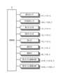
- Fig. 3 is a block diagram showing the control system of the refrigeration device 1.
- control unit 70 is configured to be able to transmit and receive various signals between the high pressure sensors H1_1-H1_4, the outside air temperature sensors 224_1-224_4, the first oil valves V1_1-V1_4, the second oil valves V2_1-V2_4, the return valves V3_1-V3_4, the pressure reducing valves 41_1-41_4, the oil supply valves 62_1-62_4, the first oil amount detection units 211E_1-211E_4, and the second oil amount detection units 212E_1-212E_4.
- the control unit 70 determines whether the amount of oil in the oil separator 23 is less than the first threshold value based on the detection results of the first oil amount detection unit 211E and the second oil amount detection unit 212E in each refrigeration unit 20.
- the first threshold is an example of a predetermined threshold of the present disclosure.
- the first threshold is the minimum amount of oil required in the oil separator 23 to supply sufficient oil to the first and second compressors 211 and 212.
- the first threshold is determined in advance based on the capacity of each of the first and second compressors 211 and 212, etc.
- the first threshold may also be determined in advance based on the initial value of the oil holding amount of each of the first and second compressors 211 and 212, or the initial value of the oil level position, etc.
- an oil level detection unit such as an oil level switch is provided in the compressor, but in the refrigeration system 1 disclosed herein, the amount of oil in the oil separator 23 is determined using the first and second oil level detection units 211E, 212E that are generally provided, so there is no need to provide the refrigeration system 1 with a new configuration to determine the amount of oil in the oil separator 23. Therefore, the amount of oil in the oil separator 23 can be determined at a relatively low cost.
- the control unit 70 also selectively controls the return valve V3 and oil supply valve 62 of each freezing unit 20 to perform a first control for circulating oil within each freezing unit 20, and a second control for supplying oil from within one of the freezing units to the other freezing unit.
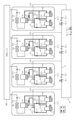
- FIG. 4 is a diagram for explaining the first control.
- FIG. 4 and FIG. 5 described later show only the main components, and the arrangement of the piping may differ from the example shown in FIG. 2.
- the suffixes "_1" to "_4" are omitted for the internal configuration of the refrigeration units 20_1 to 20_4.
- the pipes shown in solid lines are pipes through which oil, refrigerant, or a mixture of these flows.
- the pipes shown in dashed lines are pipes through which oil, refrigerant, or a mixture of these does not flow.
- when the figure showing the oil supply valve 62 is filled in it indicates that the valve is open, and when it is filled in, it indicates that the valve is closed.
- the control unit 70 opens the return valves V3 of all the refrigeration units 20 and closes all the oil supply valves 62 to drive the compression units 21. This allows oil to circulate between the first and second compressors 211, 212 and the oil separator 23 in each refrigeration unit 20, and restricts the movement of oil between the multiple refrigeration units 20 via the oil supply pipes 61.
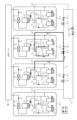
- FIG. 5 is a diagram for explaining the second control.
- the second control is a control for supplying oil from another freezing unit to a freezing unit in which the oil in the oil separator 23 falls below the first threshold.
- a freezing unit to which oil is supplied when the oil in the oil separator 23 falls below the first threshold is referred to as a "target unit.”
- FIG. 5 shows an example of the second control when freezing unit 20_3 is the target unit.
- FIG. 5 shows a case in which only one freezer unit 20_3 out of the four freezer units 20_1 to 20_4 is the target unit, but the present disclosure is not limited to this.
- the N e.g., four
- multiple units e.g., two or h is three
- the control unit 70 closes the return valve V3 of the target unit and opens the return valve V3 of the freezing units 20 other than the target unit.
- the control unit 70 then opens the oil supply valve 62_2, which is located between the oil return pipe Q1 of the target unit (freezing unit 20_3) and the oil return pipe Q1 of the freezing unit 20_2, which is located one upstream from the target unit in the oil flow direction allowed in the oil supply pipe 61, and controls to close the other oil supply valves.
- oil is replenished from the freezing unit 20_2, which is located one upstream from the target unit (freezing unit 20_3), to the target unit.
- the freezing unit that replenishes the target unit with oil may be referred to as a replenishment unit.
- the oil supply valve 62_2 located between the target unit, refrigeration unit 20_3, and refrigeration unit 20_2, which is one unit upstream from refrigeration unit 20_3, is closed, and the other oil supply valves 62_1, 62_3, and 62_4 are maintained in an open state.
- oil flows from the oil separator 23 of the compensation unit (refrigeration unit 20_2 in the example shown in FIG. 5) through the oil return pipe Q1 and connecting pipe Q13 to the oil supply pipe 61. Then, through the connecting pipe Q13 and oil return pipe Q1 of the target unit, the oil is supplied to the first compressor 211 and second compressor 212 of the target unit. In this way, the target unit is compensated for with oil.
- the check valve 63_2 allows the oil to flow in one direction through the oil supply pipe 61. Therefore, the oil that flows into the oil supply pipe 61 from the compensation unit (refrigeration unit 20_2) flows in one direction (clockwise in the example shown in FIG. 5) through the oil supply pipe 61, passes through the oil supply valve 62_2, and flows into the oil return pipe Q1 of the target unit (refrigeration unit 20_3).
- freezing unit 20_1 and freezing unit 20_3 are the two target units
- freezing unit 20_2 and freezing unit 20_4 may be set as compensation units in the second control.
- the number of target units and compensation units does not have to be the same. For example, if the three target units are freezing units 20_1 to 20_3, only freezing unit 20_4 is the compensation unit. Also, if freezing unit 20_4 is the target unit, one to three of freezing units 20_1 to 20_3 may be the compensation units. Even in these cases, the second control allows the compensation unit to compensate for oil to the target units.
- the refrigeration unit 20 one unit upstream from the target unit is used as the compensation unit, but the present disclosure is not limited to this. At least one of the refrigeration units 20 other than the target unit may be used as the compensation unit.
- the target unit is, for example, refrigeration unit 20_2
- oil can be replenished via the oil supply pipe 61 even if the compensation unit is refrigeration unit 20_3, which is one unit downstream from refrigeration unit 20_2, rather than refrigeration unit 20_1, which is one unit upstream from refrigeration unit 20_2.
- the control unit 70 opens all of the oil valves 62 installed in the oil supply pipe 61 between the oil return pipe Q1 of the target unit and the oil return pipe Q1 of the compensation unit. For example, if the freezing unit 20_1 is the target unit and the freezing unit 20_3 is the compensation unit, the control unit 70 opens both of the oil supply valves 62_3 and 62_4 installed between the connection point between the oil return pipe Q1 of the freezing unit 20_1 and the oil supply pipe 61 to the connection point between the oil return pipe Q1 of the freezing unit 20_3 and the oil supply pipe 61. This makes it possible to supply oil from the compensation unit to the target unit even if the target unit and the compensation unit are not adjacent to each other.
- the reason for performing the second control will be explained.
- the refrigerant containing oil hereinafter, sometimes referred to as “oil-containing refrigerant”
- oil-containing refrigerant passes from the compression section 21 of each freezing unit 20 through the oil separator 23, the gas cooler 223, and the pressure reducing valve 41, is supplied to the cooling unit 50, and then returns to the compression section 21 of each freezing unit 20.
- the amount of oil-containing refrigerant returning to the compression section 21 of each freezing unit 20 is approximately the same, the amount of oil circulating through each freezing unit 20 in the first control will be approximately the same.
- the amount of oil separated by the oil separator 23 of each freezing unit 20 will be approximately the same.
- the amount of oil in the oil separator 23 of each freezing unit 20 will be equal to or greater than the first threshold.
- the first threshold value is set to a value that allows the amount of oil in the first and second compressors 211, 212 to be equal to or greater than the second threshold value by returning the oil stored in the oil separator 23 to the first and second compressors 211, 212.
- the second threshold is the minimum amount of oil required in the first and second compressors 211 and 212.
- the amount of oil in the oil separator 23 may fall below the first threshold, resulting in a refrigeration unit 20 in which the amount of oil in at least one of the first and second compressors 211, 212 cannot be increased to or above the second threshold.
- the second control is performed to prevent such malfunctions from occurring.
- FIG. 6 is a flowchart for explaining an example of the operation of the refrigeration device 1.
- FIG. 6 is a flowchart showing the operation of the refrigeration device.
- step S1 the control unit 70 starts the first control, for example, based on a user operation (step S1).
- the control unit 70 opens the return valves V3 of all the refrigeration units 20, closes all the oil supply valves 62, and starts the operation of the compression units 21 of each refrigeration unit 20, as described above (see FIG. 4).
- the oil separated from the refrigerant by the oil separator 23 is stored in the oil separator 23.
- the control unit 70 supplies the oil in the oil separator 23 to the first and second compressors 211 and 212 so that the amount of oil in both the first and second compressors 211 and 212 is equal to or greater than the second threshold.
- the control unit 70 keeps the first oil valve V1 open (maximum opening) until the amount of oil in the first compressor 211 is equal to or greater than the second threshold, and closes the first oil valve V1 (sets the opening to 0) when the amount of oil in the first compressor 211 is equal to or greater than the second threshold.
- the pressure in the oil separator 23 is higher than the pressure at the part of the first compressor 211 where the oil flows in, the oil in the oil separator 23 is supplied to the first compressor 211 due to the pressure difference.
- the refrigerant that has passed through the oil separator 23 is depressurized by the pressure reducing valve 41 and used to generate cooling air in the cooling unit 50.
- control unit 70 controls the pressure reducing valve 41 so that the pressure inside the oil separator 23 becomes a target high pressure value based on the outside air temperature, based on the detection result of the outside air temperature sensor 224. Specifically, the control unit 70 controls the pressure reducing valve 41 so that the higher the outside air temperature, the higher the pressure detected by the high pressure sensor H1.
- step S2 the control unit 70 determines whether or not the amount of oil in the oil separator 23 of any of the four refrigeration units 20 is less than the first threshold. As described above, the control unit 70 estimates (determines) that the amount of oil in the oil separator 23 is less than the first threshold when, for example, the amount of oil in at least one of the first compressor 211 and the second compressor 212 remains less than the second threshold for a predetermined period of time or more.
- step S3 the control unit 70 starts the second control.
- the control unit 70 closes the return valve V3 of the target unit, opens the return valves V3 of the refrigeration units 20 other than the target unit, and opens all oil supply valves 62 installed in the oil supply pipe 61 between the oil return pipe Q1 of the target unit and the oil return pipe Q1 of the compensation unit, while keeping the other oil supply valves 62 closed.
- the amount of oil in the oil separator 23 decreases to below the first threshold, which can cause gaseous refrigerant to flow through the oil return pipe Q1 into the compression section 21.
- the return valve V3 provided in the oil return pipe Q1 is closed to prevent the refrigerant from flowing into the compression section 21.
- the control unit 70 may control the pressure reducing valve 41 of each refrigeration unit 20 so that the pressure in the oil separator 23 of the target unit is lower than the pressure in the oil separator 23 of the compensation unit.
- control unit 70 may further perform control in the second control to make the opening degree of the first oil valve V1 and the second oil valve V2 in the compensation unit lower than the opening degree in the first control.
- the opening degree of the first oil valve V1 and the second oil valve V2 can be controlled to three levels: “100” (opening degree when the valve is fully opened), “0" (opening degree when the valve is closed), and “50" (intermediate opening degree between fully opened and closed).
- the control unit 70 controls the opening degree of the first oil valve V1 and the second oil valve V2 in the compensation unit during the second control to "50". Note that it is desirable to maintain the opening degree of the first oil valve V1 and the second oil valve V2 of the target unit at "100".
- This type of control allows the oil from the oil separator 23 in the compensation unit to flow more easily to the target unit than to the compression section 21 of the compensation unit.
- step S4 the control unit 70 determines whether the amount of oil in all compressors (first and second compressors 211, 212) of all refrigeration units 20 has reached or exceeded the second threshold value based on the detection results of the first and second oil amount detection units 211E, 212E of each refrigeration unit 20.
- control unit 70 determines that the amount of oil in all compressors of all refrigeration units 20 is not equal to or greater than the second threshold (step S4: NO), it performs the process of step S4 again after a predetermined period of time has elapsed.
- step S4 YES
- the control unit 70 determines that the amount of oil in all compressors of all refrigeration units 20 is equal to or greater than the second threshold (step S4: YES)
- it ends the second control returns operation to step S1, and resumes the first control.
- control unit 70 determines that there is no target unit in which the amount of oil in the oil separator 23 is less than the first threshold (step S2: NO), the control unit 70 returns the operation to step S1 and continues the first control.
- the refrigeration device 1 comprises N (N is an integer of 3 or more) refrigeration units 20 each having a compressor (first compressor 211, second compressor 212), an oil separator 23, and an oil return pipe Q1 that returns the oil separated from the refrigerant by the oil separator 23 to the first compressor 211 and the second compressor 212, an oil supply pipe 61 that connects the oil return pipes Q1 of the N refrigeration units 20, and an oil return pipe Q1 that is disposed between the oil return pipes Q1 of the adjacent refrigeration units 20 in the oil supply pipe 61.
- N is an integer of 3 or more
- N oil supply valves 62 are provided to control the flow of oil in the oil supply pipe 61, and when it is determined that the amount of oil in the oil separator 23 of at least one of the N refrigeration units 20 is less than a predetermined threshold, control is performed to open all oil supply valves 62 arranged in the oil supply pipe 61 between the oil return pipe Q1 of at least one of the refrigeration units (compensating units) other than the refrigeration unit (target unit) determined to have an oil amount less than the predetermined threshold, and the oil return pipe Q1 of the target unit, and to close the other oil supply valves 62.
- the target unit when there is a target unit among the N refrigeration units 20 in which the amount of oil in the oil separator 23 is less than the amount (first threshold) that can supply sufficient oil to the first and second compressors 211, 212, the target unit can be replenished with oil from the replenishment unit via the oil supply pipe 61 and the oil supply valve 62. This makes it possible to avoid malfunctions (such as breakdowns) that may occur due to a lack of oil in the first and second compressors 211, 212 of the target unit.
- the oil supply pipe 61 allows oil to flow in one direction
- the control unit 70 performs control to open the oil supply valve 62 located between the target unit and the refrigeration unit 20 that is one unit upstream in the oil flow allowed by the oil supply pipe 61 as viewed from the target unit, and to close the other oil supply valve 62.
- the refrigeration unit 20 closest to the refrigeration unit 20 to be replenished with oil in the oil flow direction of the oil supply pipe 61 and one unit upstream can be used as the replenishment unit. This allows the target unit to be reliably replenished with oil, and also shortens the time required for oil to be replenished from the replenishment unit to the target unit.
- each refrigeration unit 20 further has a return valve V3 provided in the oil return pipe Q1, and the control unit 70 performs control to close the return valve V3 of the refrigeration unit 20 (target unit) in which the amount of oil in the oil separator 23 is determined to be less than the first threshold value.
- each refrigeration unit 20 further has a pressure reducing valve 41 that reduces the pressure of the refrigerant separated by the oil separator 23, and the control unit 70 controls the pressure reducing valve 41 of each refrigeration unit 20 so that the pressure in the oil separator 23 of the target unit is lower than the pressure in the oil separator 23 of the compensation unit.
- the oil supply pipe 61 allows oil to flow in one direction, but the present disclosure is not limited to this.
- the oil supply pipe of the present disclosure may allow oil to flow in either direction.
- the control unit opens the oil supply valve provided in the oil supply pipe, and oil is supplied from one of the other refrigeration units due to the pressure difference to a refrigeration unit in which the amount of oil in the oil separator is small and the pressure in the oil separator is low.
- the control unit controls the direction of oil flow permitted by the oil supply valve, and oil is preferably supplied between the refrigeration units.
- the oil supply pipe 61 does not have to be a looped pipe.
- the oil supply pipe of the present disclosure may be, for example, a straight pipe. Even in such a case, the oil supply valve between the target unit and the compensation unit is opened. Oil is supplied from the compensation unit to the target unit.
- the target unit may be any unit other than the compensation unit.
- the refrigeration unit with the largest amount of oil remaining in its oil separator may be the compensation unit.
- oil may be supplied from multiple compensation units to one target unit. Also, the number of target units does not have to be one.
- the control unit 70 estimates (determines) the amount of oil in the oil separator 23 based on the detection results of the first and second oil amount detection units 211E, 212E provided in the first and second compressors 211, 212.
- a detection unit that detects the amount of oil in each oil separator 23 may be disposed, and the control unit 70 may determine whether the amount of oil in each oil separator 23 is less than the first threshold value based on the detection results of the detection unit.
- the connecting unit 60 has an oil supply pipe 61, an oil supply valve 62, and a check valve 63, but at least one of the oil supply valve 62 and the check valve 63 may be included in any one of the N refrigeration units 20.
- a control unit 70 is provided to control the operation of the entire refrigeration device 1.
- an independent control unit may be provided for each of the N refrigeration units 20, for example.
- the control units provided for each of the N refrigeration units 20 communicate with each other and operate in cooperation with each other, or one of the control units mainly controls the other control units, thereby performing the same operation as in the above-described embodiment.
- the oil supply valve 62_1 provided between the refrigeration units 20_1 and 20_2 may be controlled, for example, by a control unit provided in the refrigeration unit 20_1, or by a control unit provided in the refrigeration unit 20_2.
- each of the four freezing units 20 has a split heat exchanger 43.
- only one split heat exchanger may be provided for multiple freezing units.
- the piping extending from the gas cooler of each freezing unit may be connected to one split heat exchanger.
- This disclosure can be applied to refrigeration equipment.
Landscapes
- Engineering & Computer Science (AREA)
- Physics & Mathematics (AREA)
- Mechanical Engineering (AREA)
- Thermal Sciences (AREA)
- General Engineering & Computer Science (AREA)
- Devices That Are Associated With Refrigeration Equipment (AREA)
Abstract
本開示の冷凍装置は、N個の冷凍ユニットのうち、少なくともいずれかの冷凍ユニットのオイルセパレータのオイル量が所定閾値未満であると判定されたとき、前記オイル量が前記所定閾値未満であると判定された冷凍ユニット以外の少なくともいずれかの冷凍ユニットのオイル戻し配管から、前記オイル量が前記所定閾値未満であると判定された冷凍ユニットの前記オイル戻し配管までの間の補油管に配置されている全ての補油弁を開き、他の補油弁を閉じる制御を行う制御部を備える。
Description
本開示は、冷凍装置及びその制御方法に関する。
複数の圧縮機及びオイルセパレータを備えた冷凍装置が知られている。例えば特許文献1には、それぞれが圧縮機、油分離機、及び凝縮器を有する複数の冷凍機を組み合わせ接続して大容量のマルチ冷凍機を構成する技術が開示されている。また、特許文献2には、複数の圧縮機及び油分離機を内包する冷凍装置が開示されている。
複数のオイルセパレータを備えた冷凍装置においては、それぞれのオイルセパレータ内に微小な圧力差が生じ、その圧力差が原因となり複数のオイルセパレータに収容される油の量が不均一となってしまうことがある。この場合、オイルセパレータから圧縮機へ戻すオイルの量が不足してしまい、冷凍装置の動作に不具合が生じることがあるため、改善が要望されている。
本開示は、複数のオイルセパレータを備える冷凍装置において、複数のオイルセパレータに収容される油の量を調整することができる冷凍装置及びその制御方法を提供することを目的とする。
本開示の冷凍装置は、圧縮機、オイルセパレータ、及び、前記オイルセパレータにより冷媒から分離されたオイルを前記圧縮機に戻すオイル戻し配管をそれぞれ有するN(Nは2以上の整数)個の冷凍ユニットと、前記N個の冷凍ユニットがそれぞれ有する前記オイル戻し配管同士を接続している補油管と、互いに隣接する前記冷凍ユニットの前記オイル戻し配管同士の間の前記補油管に配置されており、前記補油管におけるオイルの流れを制御するN個の補油弁と、前記N個の冷凍ユニットのうち、少なくともいずれかの冷凍ユニットの前記オイルセパレータのオイル量が所定閾値未満であると判定されたとき、前記オイル量が前記所定閾値未満であると判定された冷凍ユニット以外の少なくともいずれかの冷凍ユニットの前記オイル戻し配管から、前記オイル量が前記所定閾値未満であると判定された冷凍ユニットの前記オイル戻し配管までの間の前記補油管に配置されている全ての補油弁を開き、他の補油弁を閉じる制御を行う制御部と、を備える。
本開示の制御方法は、圧縮機、オイルセパレータ、及び、前記オイルセパレータにより冷媒から分離されたオイルを前記圧縮機に戻すオイル戻し配管をそれぞれ有するN(Nは2以上の整数)個の冷凍ユニットと、前記N個の冷凍ユニットがそれぞれ有する前記オイル戻し配管同士を接続している補油管と、前記補油管における、互いに隣接する前記冷凍ユニットの前記オイル戻し配管同士の間に配置されており、前記補油管におけるオイルの流れを制御するN個の補油弁と、制御部と、を備える冷凍装置の制御方法であって、前記N個の冷凍ユニットのうち、少なくともいずれかの冷凍ユニットの前記オイルセパレータのオイル量が所定閾値未満であるか否かを判定し、少なくともいずれかの冷凍ユニットの前記オイルセパレータのオイル量が所定閾値未満であると判定されたとき、前記N個の冷凍ユニットのうち、少なくともいずれかの冷凍ユニットの前記オイルセパレータのオイル量が所定閾値未満であると判定されたとき、前記オイル量が前記所定閾値未満であると判定された冷凍ユニット以外の少なくともいずれかの冷凍ユニットの前記オイル戻し配管から、前記オイル量が前記所定閾値未満であると判定された冷凍ユニットの前記オイル戻し配管までの間の前記補油管に配置されている全ての補油弁を開き、他の補油弁を閉じる制御を行う。
本開示の冷凍装置によれば、複数のオイルセパレータを備える冷凍装置において、複数のオイルセパレータに収容される油の量を調整することができる。
以下、図面を参照しながら本開示の実施の形態について説明する。
<冷凍装置1の構成>
まず、冷凍装置の構成について説明する。図1は、本開示の実施の形態に係る冷凍装置1の概略構成を示す図である。図2は、冷凍ユニット20の概略構成を示す図である。
まず、冷凍装置の構成について説明する。図1は、本開示の実施の形態に係る冷凍装置1の概略構成を示す図である。図2は、冷凍ユニット20の概略構成を示す図である。
図1に示すように、本開示の実施の形態に係る冷凍装置1は、4個の冷凍ユニット20_1~20_4と、冷却ユニット50と、連結ユニット60と、制御部70と、を備える。
4個の冷凍ユニット20_1~20_4は、冷凍サイクルにおいて並列に配置される。なお、本実施の形態では冷凍装置1が4個の冷凍ユニット20_1~20_4を備える例について説明するが、本開示の冷凍装置は、冷凍ユニットを複数(N個)備えていればよい。すなわち、冷凍装置が備える冷凍ユニットの数は、2個、3個、または5個以上であってもよい。
以下の説明では、4個の冷凍ユニットのうち1つを20_1とし、冷凍ユニット20_1に隣接して配置された冷凍ユニットを20_2とし、冷凍ユニット20_2にさらに隣接して配置された冷凍ユニットを20_3とし、冷凍ユニット20_3にさらに隣接して配置された冷凍ユニットを20_4として説明を行う。
4個の冷凍ユニット20_1~20_4はそれぞれ同様の構成を有する。本明細書において、4個の冷凍ユニットのそれぞれを区別する必要がない場合、末尾符号「_1」、「_2」、「_3」、「_4」の記載を省略することがある。このため、4個の冷凍ユニット20_1~20_4に共通の構成を説明する図2では、末尾符号を省略して示している。
図2に示すように、冷凍ユニット20は、圧縮部21と、放熱用熱交換器22と、オイルセパレータ23と、減圧弁41と、中間冷却器42と、スプリット熱交換器43と、を備える。つまり、冷凍装置1は、冷凍ユニットと同じ個数である4個の減圧弁を備える。
圧縮部21は、第1圧縮機211と、第2圧縮機212と、備える。第1圧縮機211と第2圧縮機212は、冷凍サイクルにおいて並列に配置される。なお、圧縮部21は、1台又は3台以上の圧縮機を備えても良い。圧縮部21が3台以上の圧縮機を備える場合、当該3台以上の圧縮機は、冷凍サイクルにおいて並列に配置される。第1圧縮機211と第2圧縮機212は、同様の構成を有するため、第1圧縮機211について詳細に説明し、第2圧縮機212については簡単に説明する。
第1圧縮機211は、密閉容器を備える。密閉容器には、第1低段側吸込口211Aと、第1低段側吐出口211Bと、第1高段側吸込口211Cと、第1高段側吐出口211Dと、が形成されている。第1低段側吸込口211Aには、配管P1を介して、冷却ユニット50の蒸発器が接続されている。第1低段側吐出口211Bには、配管P2を介して、放熱用熱交換器22のインタークーラ222が接続されている。第1高段側吸込口211Cには、配管P3を介して、インタークーラ222が接続されている。第1高段側吐出口211Dには、配管P4を介して、オイルセパレータ23に接続されている。配管P4には、第1高段側吐出口211Dから吐出された冷媒が第1高段側吐出口211Dに逆流することを防止する逆止弁CV1が配置されている。
第1圧縮機211の密閉容器内には、それぞれ図示されない第1低段圧縮要素と、第1高段圧縮要素と、第1モータと、が配置されている。第1低段圧縮要素及び第1高段圧縮要素は、第1モータの回転と同期して回転する。
第1モータが回転すると、第1低段圧縮要素は、配管P1及び第1低段側吸込口211Aを介して、冷却ユニット50の蒸発器から吸入される低圧の冷媒を中間圧まで昇圧する。第1低段圧縮要素は、中間圧まで昇圧された冷媒を、第1低段側吐出口211B及び配管P2を介して、インタークーラ222へ吐出する。第1高段圧縮要素は、第1高段側吸込口211C及び配管P3を介して、インタークーラ222から吸入される中間圧の冷媒を高圧まで昇圧する。第1高段圧縮要素は、高圧まで昇圧された冷媒を、第1高段側吐出口211D及び配管P4を介して、オイルセパレータ23へ吐出する。このように、第1圧縮機211は、冷媒を二段圧縮する。
第2圧縮機212は、第2低段側吸込口212Aと、第2低段側吐出口212Bと、第2高段側吸込口212Cと、第2高段側吐出口212Dと、が形成された密閉容器を備える。第2低段側吸込口212Aには、配管P1から分岐した配管P5を介して、冷却ユニット50の蒸発器が接続されている。第2低段側吐出口212Bには、配管P2から分岐した配管P6を介して、インタークーラ222が接続されている。第2高段側吸込口212Cには、配管P3から分岐した配管P7を介して、インタークーラ222が接続されている。第2高段側吐出口212Dには、配管P4から分岐した配管P8を介して、オイルセパレータ23に接続されている。配管P8には、逆止弁CV2が配置されている。
第2圧縮機212の密閉容器内には、それぞれ図示されない第2低段圧縮要素と、第2高段圧縮要素と、第2モータと、が配置されている。第2圧縮機212は、第1圧縮機211と同様に、第2低段圧縮要素及び第2高段圧縮要素が第2モータの回転と同期して回転することにより、冷媒を二段圧縮する。
第1圧縮機211の密閉容器には、密閉容器内のオイルの残量を検出する第1オイル量検出部211Eが配置されている。第2圧縮機212の密閉容器には、密閉容器内のオイルの残量を検出する第2オイル量検出部212Eが配置されている。第1,第2オイル量検出部211E,212Eは、例えば、オイルレベルスイッチにより構成され、検出された残量に対応する信号を、制御部70へ出力する。
放熱用熱交換器22は、放熱送風機221と、インタークーラ222と、ガスクーラ223と、を備える。
放熱送風機221は、インタークーラ222及びガスクーラ223を冷却する。
インタークーラ222は、第1,第2圧縮機211,212の第1,第2低段圧縮要素から吐出された中間圧の冷媒を冷却して、第1,第2高段圧縮要素へ吐出する。
ガスクーラ223は、配管P9を介して、オイルセパレータ23に接続されている。ガスクーラ223は、配管P10を介して、中間冷却器42に接続されている。ガスクーラ223は、オイルセパレータ23から吐出された高圧の冷媒を冷却して、中間冷却器42へ吐出する。
放熱用熱交換器22の近傍には、外気温センサ224が配置されている。外気温センサ224は、外気温の検出結果に対応する信号を、制御部70へ出力する。
オイルセパレータ23は、オイル戻し配管Q1を介して、第1圧縮機211及び第2圧縮機212のそれぞれの密閉容器に接続されている。オイル戻し配管Q1は、一端がオイルセパレータ23に接続された基管Q10と、基管Q10の他端と第1圧縮機211の密閉容器とを接続する第1分岐管Q11と、基管Q10の他端と第2圧縮機212の密閉容器とを接続する第2分岐管Q12と、を備える。基管Q10のオイルセパレータ23と第1分岐管Q11及び第2分岐管Q12の分岐箇所との間には、連結ユニット60に接続される接続管Q13が接続されている。
オイルセパレータ23は、第1,第2圧縮機211,212の第1,第2高段圧縮要素から吐出された高圧の冷媒に含まれるオイルを冷媒から分離して溜める。オイルセパレータ23は、溜められたオイルを、オイル戻し配管Q1を介して、第1,第2圧縮機211,212に戻す。
第1分岐管Q11には、第1オイル弁V1が配置されている。第2分岐管Q12には、第2オイル弁V2が配置されている。基管Q10には、戻し弁V3が配置されている。第1オイル弁V1、第2オイル弁V2、及び戻し弁V3は、例えばそれぞれ電動弁により構成され、制御部70の制御により開閉する。第1オイル弁V1、第2オイル弁V2、及び戻し弁V3は、制御部70の制御により開度を複数段階で制御可能な弁であってもよい。
第1オイル弁V1、第2オイル弁V2、及び戻し弁V3の開閉により、オイルセパレータ23からのオイルの戻し先が制御される。特に、戻し弁V3の開閉により、例えばオイルセパレータ23のオイル不足時に、ガスがオイルセパレータ23からオイル戻し配管Q1に流れ込むことが防止される。
配管P10には、高圧センサH1が配置されている。高圧センサH1は、配管P10の圧力に対応する信号を、制御部70へ出力する。高圧センサH1により検出された圧力は、ガスクーラ223及びオイルセパレータ23内の圧力とほぼ同じになる。
減圧弁41は、例えば電動弁により構成されている。減圧弁41は、配管P10における高圧センサH1の配置位置よりも、中間冷却器42側に配置されている。減圧弁41は、ガスクーラ223から吐出された高圧の冷媒を減圧して、中間冷却器42の上部に吐出する。
中間冷却器42の下部は、配管P41を介して、スプリット熱交換器43の第1流路431の一端に接続されている。中間冷却器42の上部は、配管P42を介して、スプリット熱交換器43の第2流路432の一端に接続されている。配管P42には、ガス戻し電動弁V11が配置されている。中間冷却器42は、減圧弁41により減圧された冷媒を冷却する。冷却により液化された冷媒(液冷媒)は、配管P41を介して、スプリット熱交換器43の第1流路431に吐出される。冷却により液化されなかった冷媒(ガス冷媒)は、配管P42を介して、スプリット熱交換器43の第2流路432に吐出される。
スプリット熱交換器43の第1流路431の他端は、配管P43を介して、冷却ユニット50に接続されている。配管P43の途中には、配管P42から分岐した配管P44が接続されている。配管P44には、液戻し電動弁V12が配置されている。スプリット熱交換器43の第2流路432の他端は、配管P45を介して、配管P3に接続されている。
このような構成を有するスプリット熱交換器43において、液戻し電動弁V12が開いている場合、中間冷却器42から吐出された液冷媒の大部分は、第1流路431及び配管P43を通過して冷却ユニット50に流入する一方で、残りの液冷媒は、配管P44,P42を通過して、第2流路432に流入する。この残りの液冷媒の第2流路432への流入により、冷却ユニット50の蒸発器へ向けて第1流路431を通過する冷媒が過冷却される。中間冷却器42から吐出されたガス冷媒は、配管P42、第2流路432、及び、配管P45,P3,P7を通過して、第1,第2圧縮機211,212の第1,第2高段圧縮要素に戻される。
冷却ユニット50は、例えば冷凍装置1の冷却対象であるショーケースなどに配置されている。冷却ユニット50には、冷凍ユニット20_1~20_4のそれぞれから延びる配管P43_1~P43_4が接続されている。図示は省略するが、冷却ユニット50は、1または複数の減圧弁と、減圧弁と同数の蒸発器と、を備える。
冷却ユニット50の減圧弁は、例えば電動弁により構成されている。冷却ユニット50の減圧弁は、冷凍ユニット20のスプリット熱交換器43から吐出された冷媒を減圧して、蒸発器に吐出する。
冷却ユニット50の蒸発器は、減圧弁から流入する液冷媒と、当該蒸発器の周囲の空気との熱交換を行うことにより、冷却対象を冷却するための冷却空気を生成する。熱交換後の冷媒は、配管P1_1~P1_4及びP5_1~P5_4を通過して、冷凍ユニット20_1~20_4の第1,第2低段圧縮要素に戻される。
連結ユニット60は、4個の冷凍ユニット20_1~20_4がそれぞれ有するオイルセパレータ23_1~23_4同士を互いに連結する。連結ユニット60は、ループ状の補油管61と、4個の補油弁62_1~62_4と、4個の逆止弁63_1~63_4と、を有している。
補油管61は、接続管Q13_1~Q13_4を介して、冷凍ユニット20_1~20_4がそれぞれ有するオイル戻し配管Q1_1~Q1_4同士を接続する。オイル戻し配管Q1_1~Q1_4は、上述したように、それぞれオイルセパレータ23_1~23_4に接続されているため、補油管61は、4個の冷凍ユニット20_1~20_4のオイルセパレータ23_1~23_4を並列に接続していることになる。
4個の補油弁62_1~62_4は、4個の冷凍ユニット20_1~20_4と同数設けられている。4個の補油弁62_1~62_4は、補油管61に設けられている。補油弁62は、互いに隣接する冷凍ユニット20のオイル戻し配管Q1同士の間に配置されている。すなわち、補油弁62_1は、冷凍ユニット20_1のオイル戻し配管Q1_1と、冷凍ユニット20_2のオイル戻し配管Q1_2との間に配置されている。また、補油弁62_2は、冷凍ユニット20_2のオイル戻し配管Q1_2と、冷凍ユニット20_3のオイル戻し配管Q1_3との間に配置されている。補油弁62_3は、冷凍ユニット20_3のオイル戻し配管Q1_3と、冷凍ユニット20_4のオイル戻し配管Q1_4との間に配置されている。また、補油弁62_4は、冷凍ユニット20_4のオイル戻し配管Q1_4と、冷凍ユニット20_1のオイル戻し配管Q1_1との間に配置されている。
補油弁62は、例えば電動弁である。4個の補油弁62_1~62_4のそれぞれは、後述の制御部70の制御に基づいて開閉動作を行うことにより、補油管61におけるオイルの流れを制御する。
4個の逆止弁63_1~63_4は、4個の冷凍ユニット20_1~20_4と同数設けられている。4個の逆止弁63_1~63_4は、補油管61に設けられている。逆止弁63は、互いに隣接する冷凍ユニット20のオイル戻し配管Q1同士の間に、補油弁62と直列に配置されている。逆止弁63_1は、冷凍ユニット20_1のオイル戻し配管Q1_1と、冷凍ユニット20_2のオイル戻し配管Q1_2との間に配置されている。また、逆止弁63_2は、冷凍ユニット20_2のオイル戻し配管Q1_2と、冷凍ユニット20_3のオイル戻し配管Q1_3との間に配置されている。逆止弁63_3は、冷凍ユニット20_3のオイル戻し配管Q1_3と、冷凍ユニット20_4のオイル戻し配管Q1_4との間に配置されている。また、逆止弁63_4は、冷凍ユニット20_4のオイル戻し配管Q1_4と、冷凍ユニット20_1のオイル戻し配管Q1_1との間に配置されている。
逆止弁63により、補油管61は、いずれか一方向へのオイルの流れを許容するようになっている。図1に示す例では、オイルは補油管61を時計回りにのみ流れるようになっているが、本開示ではオイルが補油管を反対方向(反時計回り)に流れてもよい。
制御部70は、冷凍装置1が有する制御可能な構成を制御することで、冷凍装置1全体の動作を制御する。制御部70は、例えばCPU(Central Processing Unit)を有するプロセッサまたはマイクロコントローラ等で構成される。
図1に示す例では、冷凍装置1が制御部70を1個備えているが、本開示はこれに限定されない。例えば、冷凍ユニット20_1を制御する制御部と、冷凍ユニット20_2を制御する制御部と、冷凍ユニット20_3を制御する制御部と、冷凍ユニット20_4を制御する制御部と、がそれぞれ別体に設けられていてもよい。
この場合、4個の制御部同士が互いに連携することによって、冷凍装置1全体の動作が行われればよい。なお、冷凍ユニット20_1と冷凍ユニット20_2との間に配置されている補油弁62_1は、例えば冷凍ユニット20_1を制御する制御部によって制御されればよい。冷凍ユニット20_2と冷凍ユニット20_3との間に配置されている補油弁62_2は、例えば冷凍ユニット20_2を制御する制御部によって制御されればよい。冷凍ユニット20_3と冷凍ユニット20_4との間に配置されている補油弁62_3は、例えば冷凍ユニット20_3を制御する制御部によって制御されればよい。冷凍ユニット20_4と冷凍ユニット20_1との間に配置されている補油弁62_4は、例えば冷凍ユニット20_4を制御する制御部によって制御されればよい。
<冷凍装置1の制御系>
以下では、制御部70を含む冷凍装置1の制御系について説明する。図3は、冷凍装置1の制御系を示すブロック図である。
以下では、制御部70を含む冷凍装置1の制御系について説明する。図3は、冷凍装置1の制御系を示すブロック図である。
図3に示すように、制御部70は、高圧センサH1_1~H1_4と、外気温センサ224_1~224_4と、第1オイル弁V1_1~V1_4と、第2オイル弁V2_1~V2_4と、戻し弁V3_1~V3_4と、減圧弁41_1~41_4と、補油弁62_1~62_4と、第1オイル量検出部211E_1~211E_4と、第2オイル量検出部212E_1~212E_4と、の間で各種信号を送受信できるように構成されている。
制御部70は、各冷凍ユニット20において、第1オイル量検出部211E及び第2オイル量検出部212Eの検出結果に基づいて、オイルセパレータ23内のオイル量が第1閾値未満か否かを判定する。
第1閾値は、本開示の所定閾値の一例である。第1閾値は、オイルセパレータ23内のオイルの量が、第1,第2圧縮機211,212に十分なオイルを供給するために必要な量の最小値である。第1閾値は、第1,第2圧縮機211,212それぞれの容量等によって予め定められる。また、第1閾値は、第1,第2圧縮機211,212それぞれのオイル保持量の初期値、または油面位置の初期値などに基づいてあらかじめ決定されてもよい。
一般的な冷凍装置において、圧縮機にはオイルレベルスイッチ等のオイル量検出部が配置されているが、本開示の冷凍装置1では、一般的に設けられている第1,第2オイル量検出部211E,212Eを用いてオイルセパレータ23内のオイル量を判定するので、オイルセパレータ23内のオイル量を判定するために新しい構成を冷凍装置1に設ける必要が無くなる。このため、比較的低コストでオイルセパレータ23内のオイル量を判定できる。
また、制御部70は、各冷凍ユニット20の戻し弁V3及び補油弁62を選択的に制御して、各冷凍ユニット20の内部でそれぞれオイルを循環させる第1制御と、いずれかの冷凍ユニット内に他の冷凍ユニット内のオイルを供給する第2制御と、を行う。
図4は、第1制御について説明するための図である。図4、及び後述の図5では、簡略化のため、主要な構成のみ図示されているとともに、配管の配置等が図2に示す例と異なっている場合がある。また、図4、及び後述の図5では、冷凍ユニット20_1~20_4の内部構成については末尾符号「_1」~「_4」の記載を省略している。
図4、及び後述の図5において、実線で図示された配管は、オイル、冷媒、またはこれらの混合物が流れている配管である。破線で図示された配管は、オイル、冷媒、またはこれらの混合物が流れていない配管である。また、図4、及び後述の図5において、補油弁62を示す図形が黒塗りの場合、当該弁が開いている状態を表し、白抜きの場合、当該弁が閉じている状態を表している。
また、図4および図5において、冷却ユニット50から戻る冷媒が通過する配管P1は図示を省略している。
図4に示すように、第1制御を行う際、制御部70は、全ての冷凍ユニット20の戻し弁V3を開くとともに、全ての補油弁62を閉じて圧縮部21を駆動する。これにより、各冷凍ユニット20において、第1,第2圧縮機211,212とオイルセパレータ23との間のオイルの循環が行われるとともに、補油管61を介した、複数の冷凍ユニット20間のオイルの移動が規制される。
図5は、第2制御について説明するための図である。第2制御は、オイルセパレータ23内のオイルが第1閾値未満になった冷凍ユニットに対し、他の冷凍ユニット内のオイルを供給する制御である。以下の説明において、オイルセパレータ23内のオイルが第1閾値未満となり、オイル供給の対象となった冷凍ユニットを、被対象ユニットと記載する。図5では、冷凍ユニット20_3が被対象ユニットとなった場合の第2制御の例が示されている。
なお、図5では、4個の冷凍ユニット20_1~20_4のうち、1個の冷凍ユニット20_3のみが被対象ユニットとなった場合が示されるが、本開示はこれに限定されない。本開示では、N個(例えば、4個)の冷凍ユニットのうち、複数(例えば、2個またhは3個)のユニットが被対象ユニットとなってもよい。
第2制御を行う際、制御部70は、被対象ユニットの戻し弁V3を閉じるとともに、被対象ユニット以外の冷凍ユニット20の戻し弁V3を開く。そして、制御部70は、被対象ユニット(冷凍ユニット20_3)のオイル戻し配管Q1と、補油管61において許容されるオイルの流れ方向における、被対象ユニットから見て1つ上流側に配置されている冷凍ユニット20_2のオイル戻し配管Q1と、の間に配置されている補油弁62_2を開き、他の補油弁を閉じる制御を行う。これにより、被対象ユニット(冷凍ユニット20_3)から見て1つ上流側に配置されている冷凍ユニット20_2から、被対象ユニットにオイルの補填が行われる。なお、以下の説明において、被対象ユニットに対してオイルの補填を行う冷凍ユニットを、補填ユニットと記載することがある。
図5に示す例では、被対象ユニットである冷凍ユニット20_3と、冷凍ユニット20_3から見て1つ上流側の冷凍ユニット20_2との間に設けられている補油弁62_2が閉じられ、他の補油弁62_1,62_3,62_4は開かれた状態が維持されている。
このような制御により、補填ユニット(図5に示す例では、冷凍ユニット20_2)のオイルセパレータ23から、オイル戻し配管Q1及び接続管Q13を通って補油管61にオイルが流れる。そして、被対象ユニットの接続管Q13、およびオイル戻し配管Q1を通って、オイルが被対象ユニットの第1圧縮機211および第2圧縮機212に供給される。これにより、被対象ユニットへのオイルの補填が行われる。
上述したように、逆止弁63_2により、補油管61は一方向へのオイルの流れを許容する。このため、補填ユニット(冷凍ユニット20_2)から補油管61に流入したオイルは、補油管61内を一方向(図5に示す例では時計回り方向)に流れ、補油弁62_2を通過して被対象ユニット(冷凍ユニット20_3)のオイル戻し配管Q1に流れ込む。
なお、図5に示す例では、被対象ユニット及び補填ユニットはそれぞれ1つであったが、本開示はこれに限定されない。本開示において、被対象ユニット及び補填ユニットは複数であってもよい。
例えば冷凍ユニット20_1と冷凍ユニット20_3の2個が被対象ユニットであった場合、第2制御において、冷凍ユニット20_2と冷凍ユニット20_4とが補填ユニットとされてもよい。
被対象ユニットと補填ユニットの数は、同じでなくてもよい。例えば冷凍ユニット20_1~20_3の3個が被対象ユニットであった場合、冷凍ユニット20_4のみが補填ユニットとされる。また、例えば冷凍ユニット20_4が被対象ユニットであった場合、冷凍ユニット20_1~20_3のうち、1~3個の冷凍ユニット20が補填ユニットとされてよい。これらの場合でも、第2制御により、補填ユニットから被対象ユニットへのオイルの補填が可能である。
また、図5に示す例では、被対象ユニットから見て1つ上流側の冷凍ユニット20を補填ユニットとしていたが、本開示はこれに限定されない。被対象ユニット以外の冷凍ユニット20のうち、少なくともいずれかが補填ユニットとされてもよい。上述したように、各冷凍ユニット20はループ状の配管である補油管61により接続されているため、例えば冷凍ユニット20_2が被対象ユニットである場合、冷凍ユニット20_2から見て1つ上流側である冷凍ユニット20_1ではなく、1つ下流側である冷凍ユニット20_3が補填ユニットとされた場合でも、補油管61を介したオイルの補填は可能である。
補填ユニットが被対象ユニットから見て1つ上流側ではない場合、第2制御において、制御部70は、被対象ユニットのオイル戻し配管Q1から補填ユニットのオイル戻し配管Q1までの間の補油管61に設けられている全ての補油弁62を開く。例えば冷凍ユニット20_1が被対象ユニットであり、冷凍ユニット20_3が補填ユニットとされた場合、制御部70は、冷凍ユニット20_1のオイル戻し配管Q1と補油管61との接続箇所から、冷凍ユニット20_3のオイル戻し配管Q1と補油管61との接続箇所までの間に設けられている、補油弁62_3および補油弁62_4をいずれも開く。これにより、被対象ユニットと補填ユニットとが互いに隣接していない場合でも、補填ユニットから被対象ユニットへのオイルの補填が可能となる。
ここで、第2制御を行う理由について説明する。圧縮部21を駆動して第1制御を行う場合、オイルを含む冷媒(以下、「オイル含有冷媒」と言う場合がある)は、各冷凍ユニット20の圧縮部21から、オイルセパレータ23、ガスクーラ223、及び減圧弁41を通過して、冷却ユニット50に供給された後、各冷凍ユニット20の圧縮部21に戻る。この場合、各冷凍ユニット20の圧縮部21に戻るオイル含有冷媒の量がほぼ同じであれば、第1制御において、各冷凍ユニット20を循環するオイル量は、ほぼ同じになる。すなわち、各冷凍ユニット20のオイルセパレータ23により分離されるオイルの量は、ほぼ同じになる。その結果、各冷凍ユニット20のオイルセパレータ23内のオイルの量は、いずれも第1閾値以上になる。
第1閾値は、オイルセパレータ23に溜められたオイルを第1,第2圧縮機211,212に戻すことにより、第1,第2圧縮機211,212内のオイル量を第2閾値以上にすることができる値に設定されている。
第2閾値は、第1,第2圧縮機211,212内において最低限必要なオイルの量である。
しかしながら、例えば以下の(1)~(3)のような場合、第1制御において、いずれかの冷凍ユニット20を循環するオイル量に偏りが生じうる。
(1)冷却ユニット50の蒸発器から各冷凍ユニット20の圧縮部21にオイル含有冷媒が戻る際の分流の具合により、それぞれの圧縮部21に戻るオイル含有冷媒の量に差が生じた場合。
(2)各冷凍ユニット20における中間圧と高圧との差が異なることに起因して、冷凍ユニット20毎にオイルセパレータ23から圧縮部21に戻るオイルの速度が異なってしまい、オイルセパレータ23からオイルが無くなる速度が異なる場合。
(3)冷凍ユニット20毎に、圧縮部21を構成する第1,第2圧縮機211,212の運転周波数が異なる場合。
これらの(1)~(3)の場合、例えば、オイルセパレータ23内のオイルの量が、第1閾値未満になってしまい、第1,第2圧縮機211,212のうち少なくとも一方のオイル量を第2閾値以上にすることができなくなってしまう冷凍ユニット20が生じうる。第2制御は、このような不具合の発生を抑制するために行われる。
次に、図6を参照して、冷凍装置1の動作について説明する。図6は、冷凍装置1の動作例を説明するためのフローチャートである。
図6で例示する冷凍装置1の動作は、第1,第2圧縮機211,212により二段圧縮された冷媒を用いて、冷却対象を冷却する動作である。図6は、冷凍装置の動作を示すフローチャートである。
ステップS1において、例えばユーザの操作などに基づいて、制御部70は、第1制御を開始する(ステップS1)。制御部70は、第1制御を開始する際、上述したように、全ての冷凍ユニット20の戻し弁V3を開くとともに、全ての補油弁62を閉じ、各冷凍ユニット20の圧縮部21の運転を開始する(図4参照)。
圧縮部21の運転が開始されると、圧縮部21により二段圧縮された冷媒がオイルセパレータ23に流入する。
オイルセパレータ23により冷媒から分離されたオイルは、オイルセパレータ23に溜められる。制御部70は、第1,第2オイル量検出部211E,212Eの検出結果に基づいて、第1,第2圧縮機211,212の両方のオイルの量が第2閾値以上になるように、オイルセパレータ23内のオイルを第1,第2圧縮機211,212に供給する。例えば、制御部70は、第1圧縮機211のオイルの量が第2閾値以上になるまで、第1オイル弁V1を開いた(開度が最大の)状態を維持する一方で、第2閾値以上になった場合第1オイル弁V1を閉じる(開度を0にする)。このとき、オイルセパレータ23内の圧力が第1圧縮機211におけるオイルが流入する部位の圧力より高いため、当該圧力の差により、オイルセパレータ23内のオイルが第1圧縮機211内に供給される。
一方で、オイルセパレータ23を通過した冷媒は、減圧弁41により減圧されて、冷却ユニット50における冷却空気の生成に利用される。
また、制御部70は、第1制御を行っている間、外気温センサ224における検出結果に基づいて、オイルセパレータ23内の圧力が外気温に基づく目標高圧値になるように、減圧弁41を制御する。具体的には、制御部70は、外気温が高いほど、高圧センサH1で検出される圧力が高くなるように、減圧弁41を制御する。
ステップS2において、制御部70は、4個の冷凍ユニット20のうち、オイルセパレータ23内のオイルの量が第1閾値未満となっているものがあるか否かを判定する。上述したように、制御部70は、例えば、第1圧縮機211及び第2圧縮機212のうち少なくとも一方のオイルの量が第2閾値未満の状態が所定時間以上継続した場合、オイルセパレータ23内のオイルの量が第1閾値未満であると推定(判定)する。
オイルセパレータ23内のオイルの量が第1閾値未満となっている冷凍ユニット20(被対象ユニット)があると判定した場合(ステップS2:YES)、ステップS3において、制御部70は、第2制御を開始する。第2制御を開始する際、上述したように、制御部70は、被対象ユニットの戻し弁V3を閉じ、被対象ユニット以外の冷凍ユニット20の戻し弁V3を開くとともに、被対象ユニットのオイル戻し配管Q1から補填ユニットのオイル戻し配管Q1までの間の補油管61に設けられている全ての補油弁62を開き、その他の補油弁62については、閉じた状態を維持する。
これにより、第2制御では、図5に示すように、補填ユニットから、被対象ユニットに対してオイルの補填が行われる。第2制御では、補填ユニットおよび被対象ユニット以外の冷凍ユニット20については、他の冷凍ユニット20との間のオイルの移動は生じない。このような第2制御により、各冷凍ユニット20の第1,第2圧縮機211,212内にオイルが不足する事態を防止できる。
被対象ユニットでは、オイルセパレータ23内のオイルの量が第1閾値未満まで少なくなっていることにより、ガス状の冷媒がオイル戻し配管Q1を通って圧縮部21側へ流入することがある。第2制御では、オイル戻し配管Q1に設けられた戻し弁V3を閉じることにより、冷媒が圧縮部21側へ流入することを防止できる。
なお、第2制御において、被対象ユニットのオイルセパレータ23内の圧力が、補填ユニットのオイルセパレータ23内の圧力よりも高い場合、被対象ユニットから補填ユニットまでの間の補油管61に配置されている補油弁62を開いても、補填ユニットからのオイルが被対象ユニットに流入しにくいことがある。このような事態を防止するため、制御部70は、第2制御において、上記の制御に加えて、被対象ユニットのオイルセパレータ23内の圧力が、補填ユニットのオイルセパレータ23内の圧力より低くなるように、各冷凍ユニット20の減圧弁41を制御するようにしてもよい。
また、第2制御中の補填ユニットにおいて、オイルセパレータ23から自ユニットの第1,第2圧縮機211,212へオイルを供給するよりも、被対象ユニットへのオイルの供給を優先した方がよいことがある。このような場合のために、制御部70は、第2制御において、補填ユニットにおける第1オイル弁V1及び第2オイル弁V2の開度を、第1制御における開度よりも低くする制御をさらに行ってもよい。
以下、当該制御について具体例を挙げて説明する。第1オイル弁V1及び第2オイル弁V2の開度が「100」(弁を最大限に開いた場合の開度)、「0」(弁を閉じた場合の開度)、および「50」(弁を最大限に開いた場合と閉じた場合との中間の開度)の3段階に制御可能であったとする。この場合、制御部70は、第1制御における第1オイル弁V1及び第2オイル弁V2の開度が「100」であったとすると、第2制御中の補填ユニットにおいては、第1オイル弁V1及び第2オイル弁V2の開度を「50」に制御する。なお、被対象ユニットの第1オイル弁V1及び第2オイル弁V2の開度は「100」を維持することが望ましい。
このような制御により、補填ユニットにおいて、オイルセパレータ23からのオイルを、当該ユニットの圧縮部21よりも被対象ユニットに流れやすくすることができる。
図6の説明に戻る。ステップS4において、制御部70は、各冷凍ユニット20の第1,第2オイル量検出部211E,212Eの検出結果に基づいて、全ての冷凍ユニット20の全ての圧縮機(第1,第2圧縮機211,212)内のオイルの量が第2閾値以上になったか否かを判定する。
制御部70は、全ての冷凍ユニット20の全ての圧縮機内のオイルの量が第2閾値以上になっていないと判定した場合(ステップS4:NO)、所定期間経過後に、再度ステップS4の処理を行う。
一方、制御部70は、全ての冷凍ユニット20の全ての圧縮機内のオイルの量が第2閾値以上になったと判定した場合(ステップS4:YES)、第2制御を終了して動作をステップS1に戻し、第1制御を再開する。
また、制御部70は、オイルセパレータ23内のオイルの量が第1閾値未満となっている被対象ユニットがないと判定した場合(ステップS2:NO)、動作をステップS1に戻し、第1制御を継続する。
以上のステップS1~S4の動作は、例えばユーザにより冷凍装置1の運転を終了する操作が行われるまで実行される。
以上説明したように、本開示の実施の形態に係る冷凍装置1は、圧縮機(第1圧縮機211,第2圧縮機212)、オイルセパレータ23、及び、オイルセパレータ23により冷媒から分離されたオイルを第1圧縮機211,第2圧縮機212に戻すオイル戻し配管Q1をそれぞれ有するN(Nは3以上の整数)個の冷凍ユニット20と、N個の冷凍ユニット20がそれぞれ有するオイル戻し配管Q1同士を接続している補油管61と、補油管61における、互いに隣接する冷凍ユニット20のオイル戻し配管Q1同士の間に配置されており、補油管61におけるオイルの流れを制御するN個の補油弁62と、N個の冷凍ユニット20のうち、少なくともいずれかの冷凍ユニット20のオイルセパレータ23のオイル量が所定閾値未満であると判定されたとき、オイル量が所定閾値未満であると判定された冷凍ユニット(被対象ユニット)以外の少なくともいずれかの冷凍ユニット(補填ユニット)のオイル戻し配管Q1から、被対象ユニットのオイル戻し配管Q1までの間の補油管61に配置されている全ての補油弁62を開き、他の補油弁62を閉じる制御を行う。
このような構成により、本開示の実施の形態に係る冷凍装置1は、N個の冷凍ユニット20のうち、オイルセパレータ23内のオイル量が、第1,第2圧縮機211,212に十分なオイルを供給できる量(第1閾値)未満である被対象ユニットがある場合、補油管61および補油弁62を介して、補填ユニットから被対象ユニットへオイルを補填することができる。これにより、被対象ユニットの第1,第2圧縮機211,212内のオイルが不足することにより生じうる不具合(故障など)を回避できる。
また、本開示の実施の形態に係る冷凍装置1において、補油管61は、いずれか一方向へのオイルの流れを許容しており、制御部70は、被対象ユニットから見て、補油管61により許容されるオイルの流れにおける1つ上流側の冷凍ユニット20と、被対象ユニットとの間に配置されている補油弁62を開き、他の補油弁62を閉じる制御を行う。
これにより、オイルを補填したい冷凍ユニット20から見て補油管61のオイルの流れ方向において最も近い、1つ上流側の冷凍ユニット20を補填ユニットとすることができる。このため、被対象ユニットに確実にオイルを補填できるとともに、補填ユニットから被対象ユニットへオイルが補填されるために要する時間を短縮できる。
また、本開示の実施の形態に係る冷凍装置1において、各冷凍ユニット20は、オイル戻し配管Q1に設けられている戻し弁V3をさらに有し、制御部70は、オイルセパレータ23のオイル量が第1閾値未満であると判定された冷凍ユニット20(被対象ユニット)の戻し弁V3を閉じる制御を行う。
これにより、被対象ユニットにおいて、冷媒ガスがオイルセパレータ23からオイル戻し配管Q1に流れ込むことが防止される。
また、本開示の実施の形態に係る冷凍装置1において、各冷凍ユニット20は、オイルセパレータ23により分離された冷媒を減圧する減圧弁41をさらに有し、制御部70は、被対象ユニットのオイルセパレータ23内の圧力が、補填ユニットのオイルセパレータ23内の圧力より低くなるように、各冷凍ユニット20の減圧弁41を制御する。
これにより、被対象ユニットのオイルセパレータ23内の圧力が低下するので、補填ユニットからのオイルが被対象ユニットのオイルセパレータ23に流れ込みやすくなる。
[変形例]
本開示は、以上説明した実施の形態に限られない。本開示には、その趣旨を逸脱しない範囲内で、種々の変形を加えることができる。また、上記実施形態及び以下に示される変形例は、正常に機能する限り、どのように組み合わせてもよい。
本開示は、以上説明した実施の形態に限られない。本開示には、その趣旨を逸脱しない範囲内で、種々の変形を加えることができる。また、上記実施形態及び以下に示される変形例は、正常に機能する限り、どのように組み合わせてもよい。
上述した実施の形態では、補油管61がいずれか一方向へのオイルの流れを許容するとしたが、本開示はこれに限られない。本開示の補油管は、いずれの方向へのオイルの流れを許容してもよい。このような場合でも、制御部が補油管に設けられた補油弁を開くことにより、オイルセパレータ内のオイル量が少なくオイルセパレータ内の圧力が小さい冷凍ユニットに対して、圧力差によって他のいずれかの冷凍ユニットからオイルが補填される。この場合、例えば補油弁を方向制御弁とすることにより、補油弁が許容するオイルの流れ方向が制御部により制御され、冷凍ユニット間のオイルの補填が好適に行われる。
また、補油管61がループ状の配管ではなくてもよい。本開示の補油管は、例えば直線状の配管であってもよい。このような場合でも、被対象ユニットと補填ユニットとの間の補油弁を開くことにより。補填ユニットから被対象ユニットにオイルが補填される。なお、この場合、被対象ユニットは補填ユニット以外のいずれのユニットであってもよく、例えばオイルセパレータ内のオイル残量が最も多い冷凍ユニットが補填ユニットとされればよい。例えば1つの被対象ユニットに対して複数の補填ユニットからオイルが補填されてもよい。また、被対象ユニットも1つでなくてもよい。
また、上述した実施の形態では、第1,第2圧縮機211,212に設けられた第1,第2オイル量検出部211E,212Eの検出結果に基づいて、制御部70は、オイルセパレータ23内のオイル量を推定(判定)していた。しかしながら、本開示では、例えばオイルセパレータ23毎に当該オイルセパレータ23内のオイルの量を検出する検出部を配置し、当該検出部における検出結果に基づいて、制御部70が、各オイルセパレータ23内のオイルの量が第1閾値未満か否かを判定してもよい。
上述した実施の形態では、連結ユニット60が、補油管61、補油弁62、及び逆止弁63を有する例について説明したが、補油弁62及び逆止弁63の少なくともいずれかは、N個の冷凍ユニット20のいずれかに含まれてもよい。
上述した実施の形態では、冷凍装置1全体の動作を制御する制御部70が設けられていた。本開示では、例えばN個の冷凍ユニット20毎に独立した制御部が設けられてもよい。この場合、N個の冷凍ユニット20毎に設けられた制御部同士が互いに通信を行い、連携して動作する、またはいずれか1つの制御部が主体となって他の制御部を制御することにより、上述した実施の形態と同様の動作を行うことができる。また、この場合、冷凍ユニット20_1と冷凍ユニット20_2との間に設けられた補油弁62_1の制御は、例えば冷凍ユニット20_1に設けられた制御部により行われてもよいし、冷凍ユニット20_2に設けられた制御部により行われてもよい。
上述した実施の形態では、4個の冷凍ユニット20がそれぞれスプリット熱交換器43を有する場合について説明した。本開示では、例えば複数の冷凍ユニットに対して、スプリット熱交換器が1個のみ設けられていてもよい。この場合、各冷凍ユニットのガスクーラから延びる配管が、1個のスプリット熱交換器に接続されればよい。
2023年8月3日出願の特願2023-127064の日本出願に含まれる明細書、図面および要約書の開示内容は、全て本願に援用される。
本開示は、冷凍装置に適用できる。
1 冷凍装置
20 冷凍ユニット
21 圧縮部
22 放熱用熱交換器
23 オイルセパレータ
41 減圧弁
42 中間冷却器
43 スプリット熱交換器
50 冷却ユニット
60 連結ユニット
61 補油管
62 補油弁
63 逆止弁
70 制御部
211 第2圧縮機
211A 第1低段側吸込口
211B 第1低段側吐出口
211C 第1高段側吸込口
211D 第1高段側吐出口
211E 第1オイル量検出部
212 第2圧縮機
212A 第2低段側吸込口
212B 第2低段側吐出口
212C 第2高段側吸込口
212D 第2高段側吐出口
212E 第2オイル量検出部
221 放熱送風機
222 インタークーラ
223 ガスクーラ
224 外気温センサ
431 第1流路
432 第2流路
CV1 逆止弁
CV2 逆止弁
H1 高圧センサ
P1,P2,P3,P4,P5,P6,P7,P8,P9,P10、P41,P42,
P43,P44,P45 配管
Q1 オイル戻し配管
Q10 基管
Q11 第1分岐管
Q12 第2分岐管
Q13 接続管
V1 第1オイル弁
V11 ガス戻し電動弁
V12 液戻し電動弁
V2 第2オイル弁
V3 戻し弁
Claims (8)
- 圧縮機、オイルセパレータ、及び、前記オイルセパレータにより冷媒から分離されたオイルを前記圧縮機に戻すオイル戻し配管をそれぞれ有するN(Nは2以上の整数)個の冷凍ユニットと、
前記N個の冷凍ユニットがそれぞれ有する前記オイル戻し配管同士を接続している補油管と、
互いに隣接する前記冷凍ユニットの前記オイル戻し配管同士の間の前記補油管に配置されており、前記補油管におけるオイルの流れを制御するN個の補油弁と、
前記N個の冷凍ユニットのうち、少なくともいずれかの冷凍ユニットの前記オイルセパレータのオイル量が所定閾値未満であると判定されたとき、前記オイル量が前記所定閾値未満であると判定された冷凍ユニット以外の少なくともいずれかの冷凍ユニットの前記オイル戻し配管から、前記オイル量が前記所定閾値未満であると判定された冷凍ユニットの前記オイル戻し配管までの間の前記補油管に配置されている全ての補油弁を開き、他の補油弁を閉じる制御を行う制御部と、
を備える、冷凍装置。 - 前記補油管は、いずれか一方向への前記オイルの流れを許容しており、
前記制御部は、前記オイル量が前記所定閾値未満であると判定された冷凍ユニットから見て、前記オイルの流れ方向において1つ上流側の冷凍ユニットと、前記オイル量が前記所定閾値未満であると判定された冷凍ユニットとの間に配置されている補油弁を開き、他の補油弁を閉じる制御を行う、
請求項1に記載の冷凍装置。 - 前記N個の冷凍ユニットのそれぞれは、前記オイル戻し配管に設けられている戻し弁をさらに有し、
前記制御部は、前記オイル量が所定閾値未満であると判定された冷凍ユニットの前記戻し弁を閉じる制御を行う、
請求項1に記載の冷凍装置。 - 前記補油管は、ループ状の配管を有する、
請求項1に記載の冷凍装置。 - 前記補油管は、前記補油管により許容される前記オイルの流れとは反対方向のオイルの流れを規制する逆止弁をさらに備える、
請求項2に記載の冷凍装置。 - 前記補油弁は、前記補油管における前記オイルの流れ方向を制御可能な方向制御弁である、
請求項1に記載の冷凍装置。 - 前記N個の冷凍ユニットは、前記オイルセパレータにより分離された前記冷媒を減圧する減圧弁をさらに有し、
前記制御部は、前記オイル量が所定閾値未満であると判定された冷凍ユニットのオイルセパレータ内の圧力が、前記オイル量が所定閾値未満であると判定されていない冷凍ユニットのオイルセパレータ内の圧力より低くなるように、各冷凍ユニットの減圧弁を制御する、
請求項1に記載の冷凍装置。 - 圧縮機、オイルセパレータ、及び、前記オイルセパレータにより冷媒から分離されたオイルを前記圧縮機に戻すオイル戻し配管をそれぞれ有するN(Nは2以上の整数)個の冷凍ユニットと、前記N個の冷凍ユニットがそれぞれ有する前記オイル戻し配管同士を接続している補油管と、前記補油管における、互いに隣接する前記冷凍ユニットの前記オイル戻し配管同士の間に配置されており、前記補油管におけるオイルの流れを制御するN個の補油弁と、制御部と、を備える冷凍装置の制御方法であって、
前記N個の冷凍ユニットのうち、少なくともいずれかの冷凍ユニットの前記オイルセパレータのオイル量が所定閾値未満であるか否かを判定し、
前記N個の冷凍ユニットのうち、少なくともいずれかの冷凍ユニットの前記オイルセパレータのオイル量が所定閾値未満であると判定されたとき、前記オイル量が前記所定閾値未満であると判定された冷凍ユニット以外の少なくともいずれかの冷凍ユニットの前記オイル戻し配管から、前記オイル量が前記所定閾値未満であると判定された冷凍ユニットの前記オイル戻し配管までの間の前記補油管に配置されている全ての補油弁を開き、他の補油弁を閉じる制御を行う、
制御方法。
Priority Applications (1)
| Application Number | Priority Date | Filing Date | Title |
|---|---|---|---|
| JP2025537352A JPWO2025028362A1 (ja) | 2023-08-03 | 2024-07-24 |
Applications Claiming Priority (2)
| Application Number | Priority Date | Filing Date | Title |
|---|---|---|---|
| JP2023127064 | 2023-08-03 | ||
| JP2023-127064 | 2023-08-03 |
Publications (1)
| Publication Number | Publication Date |
|---|---|
| WO2025028362A1 true WO2025028362A1 (ja) | 2025-02-06 |
Family
ID=94395282
Family Applications (1)
| Application Number | Title | Priority Date | Filing Date |
|---|---|---|---|
| PCT/JP2024/026467 Pending WO2025028362A1 (ja) | 2023-08-03 | 2024-07-24 | 冷凍装置及び制御方法 |
Country Status (2)
| Country | Link |
|---|---|
| JP (1) | JPWO2025028362A1 (ja) |
| WO (1) | WO2025028362A1 (ja) |
Citations (8)
| Publication number | Priority date | Publication date | Assignee | Title |
|---|---|---|---|---|
| JPH01173686A (ja) | 1987-12-28 | 1989-07-10 | Omron Tateisi Electron Co | 波長可変型半導体レーザ |
| JPH0217763A (ja) | 1988-07-06 | 1990-01-22 | Ricoh Co Ltd | ファクシミリ装置 |
| JP2001124388A (ja) * | 1999-10-29 | 2001-05-11 | Sanyo Electric Co Ltd | 空気調和装置 |
| JP2001336840A (ja) * | 2000-05-30 | 2001-12-07 | Sanyo Electric Co Ltd | 空気調和装置 |
| US20110155816A1 (en) * | 2009-12-24 | 2011-06-30 | Jeong Hojong | Air Conditioner |
| JP2013204927A (ja) * | 2012-03-28 | 2013-10-07 | Toshiba Carrier Corp | 冷凍装置 |
| JP2023117097A (ja) * | 2022-02-10 | 2023-08-23 | パナソニックIpマネジメント株式会社 | 冷凍装置 |
| JP2023127064A (ja) | 2022-03-01 | 2023-09-13 | プライムプラネットエナジー&ソリューションズ株式会社 | 電池モジュール |
-
2024
- 2024-07-24 JP JP2025537352A patent/JPWO2025028362A1/ja active Pending
- 2024-07-24 WO PCT/JP2024/026467 patent/WO2025028362A1/ja active Pending
Patent Citations (8)
| Publication number | Priority date | Publication date | Assignee | Title |
|---|---|---|---|---|
| JPH01173686A (ja) | 1987-12-28 | 1989-07-10 | Omron Tateisi Electron Co | 波長可変型半導体レーザ |
| JPH0217763A (ja) | 1988-07-06 | 1990-01-22 | Ricoh Co Ltd | ファクシミリ装置 |
| JP2001124388A (ja) * | 1999-10-29 | 2001-05-11 | Sanyo Electric Co Ltd | 空気調和装置 |
| JP2001336840A (ja) * | 2000-05-30 | 2001-12-07 | Sanyo Electric Co Ltd | 空気調和装置 |
| US20110155816A1 (en) * | 2009-12-24 | 2011-06-30 | Jeong Hojong | Air Conditioner |
| JP2013204927A (ja) * | 2012-03-28 | 2013-10-07 | Toshiba Carrier Corp | 冷凍装置 |
| JP2023117097A (ja) * | 2022-02-10 | 2023-08-23 | パナソニックIpマネジメント株式会社 | 冷凍装置 |
| JP2023127064A (ja) | 2022-03-01 | 2023-09-13 | プライムプラネットエナジー&ソリューションズ株式会社 | 電池モジュール |
Also Published As
| Publication number | Publication date |
|---|---|
| JPWO2025028362A1 (ja) | 2025-02-06 |
Similar Documents
| Publication | Publication Date | Title |
|---|---|---|
| EP2495512B1 (en) | Refrigeration cycle device | |
| JP4360203B2 (ja) | 冷凍装置 | |
| JP5932971B2 (ja) | 冷凍装置及び冷凍サイクル装置 | |
| KR20130050700A (ko) | 비공비 혼합냉매를 이용한 냉장고 및 그 제어방법 | |
| JP7150148B2 (ja) | 室外ユニット、冷凍サイクル装置および冷凍機 | |
| US12410942B2 (en) | Heat source unit and refrigeration apparatus | |
| JP5764734B2 (ja) | 冷凍装置 | |
| KR20210075922A (ko) | 냉장고 | |
| EP2314954B1 (en) | Refrigeration device | |
| KR102237596B1 (ko) | 냉장고 및 그 제어방법 | |
| WO2011072679A1 (en) | A vapour compression system with split evaporator | |
| WO2025028362A1 (ja) | 冷凍装置及び制御方法 | |
| JP6835176B1 (ja) | 冷凍装置 | |
| JP7668467B2 (ja) | 冷凍装置 | |
| US20050150246A1 (en) | Refrigerating equipment | |
| WO2025028243A1 (ja) | 冷凍装置及び制御方法 | |
| JP5764736B2 (ja) | 冷凍装置 | |
| JP5764735B2 (ja) | 冷凍装置 | |
| US20170276416A1 (en) | Refrigeration apparatus | |
| KR100743753B1 (ko) | 냉장고 및 냉장고의 제어 방법 | |
| CN118140103A (zh) | 制冷循环装置 | |
| KR102246351B1 (ko) | 냉장고 | |
| JPH0480555A (ja) | 冷凍装置 | |
| JP7832513B2 (ja) | 空気調和装置 | |
| US20230251004A1 (en) | Refrigeration apparatus |
Legal Events
| Date | Code | Title | Description |
|---|---|---|---|
| 121 | Ep: the epo has been informed by wipo that ep was designated in this application |
Ref document number: 24849017 Country of ref document: EP Kind code of ref document: A1 |
|
| ENP | Entry into the national phase |
Ref document number: 2025537352 Country of ref document: JP Kind code of ref document: A |
|
| WWE | Wipo information: entry into national phase |
Ref document number: 2024849017 Country of ref document: EP |
|
| NENP | Non-entry into the national phase |
Ref country code: DE |