WO2025028362A1 - Dispositif de réfrigération et procédé de commande - Google Patents
Dispositif de réfrigération et procédé de commande Download PDFInfo
- Publication number
- WO2025028362A1 WO2025028362A1 PCT/JP2024/026467 JP2024026467W WO2025028362A1 WO 2025028362 A1 WO2025028362 A1 WO 2025028362A1 JP 2024026467 W JP2024026467 W JP 2024026467W WO 2025028362 A1 WO2025028362 A1 WO 2025028362A1
- Authority
- WO
- WIPO (PCT)
- Prior art keywords
- oil
- unit
- refrigeration
- pipe
- units
- Prior art date
- Legal status (The legal status is an assumption and is not a legal conclusion. Google has not performed a legal analysis and makes no representation as to the accuracy of the status listed.)
- Pending
Links
Images


Classifications
-
- F—MECHANICAL ENGINEERING; LIGHTING; HEATING; WEAPONS; BLASTING
- F25—REFRIGERATION OR COOLING; COMBINED HEATING AND REFRIGERATION SYSTEMS; HEAT PUMP SYSTEMS; MANUFACTURE OR STORAGE OF ICE; LIQUEFACTION SOLIDIFICATION OF GASES
- F25B—REFRIGERATION MACHINES, PLANTS OR SYSTEMS; COMBINED HEATING AND REFRIGERATION SYSTEMS; HEAT PUMP SYSTEMS
- F25B1/00—Compression machines, plants or systems with non-reversible cycle
Definitions
- This disclosure relates to a refrigeration device and a control method thereof.
- Patent Document 1 discloses a technology for combining and connecting multiple refrigerators, each of which has a compressor, oil separator, and condenser, to form a large-capacity multi-refrigeration system.
- Patent Document 2 discloses a refrigeration system incorporating multiple compressors and oil separators.
- the present disclosure aims to provide a refrigeration device equipped with multiple oil separators that can adjust the amount of oil contained in the multiple oil separators, and a control method thereof.
- the refrigeration device of the present disclosure includes N (N is an integer of 2 or more) refrigeration units each having a compressor, an oil separator, and an oil return pipe that returns oil separated from the refrigerant by the oil separator to the compressor; an oil supply pipe connecting the oil return pipes of the N refrigeration units; N oil supply valves that are arranged in the oil supply pipe between the oil return pipes of the adjacent refrigeration units and control the flow of oil in the oil supply pipe; and a control unit that, when it is determined that the amount of oil in the oil separator of at least one of the N refrigeration units is less than a predetermined threshold, opens all oil supply valves arranged in the oil supply pipe between the oil return pipe of at least one of the refrigeration units other than the refrigeration unit whose oil amount is determined to be less than the predetermined threshold and closes the other oil supply valves.
- the control method disclosed herein is a control method for a refrigeration system including N (N is an integer of 2 or more) refrigeration units each having a compressor, an oil separator, and an oil return pipe for returning oil separated from a refrigerant by the oil separator to the compressor, an oil supply pipe connecting the oil return pipes of the N refrigeration units, N oil supply valves arranged in the oil supply pipe between the oil return pipes of the adjacent refrigeration units and for controlling the flow of oil in the oil supply pipe, and a control unit, and further including: When it is determined that the oil amount in the oil separator of at least one of the refrigeration units is less than the predetermined threshold, and when it is determined that the oil amount in the oil separator of at least one of the N refrigeration units is less than the predetermined threshold, control is performed to open all the oil supply valves arranged in the oil supply pipe between the oil return pipe of at least one of the refrigeration units other than the refrigeration unit determined to have the oil amount less than the predetermined threshold and the oil return pipe of the refrigeration unit determined to have the oil amount less than the predetermined
- the amount of oil contained in the multiple oil separators can be adjusted.
- FIG. 1 is a diagram showing a schematic configuration of a refrigeration device according to an embodiment of the present disclosure.
- FIG. 1 is a diagram showing a schematic configuration of a refrigeration unit.
- Block diagram showing the control system of the refrigeration device FIG. 4 is a diagram for explaining a first control.
- FIG. 4 is a diagram for explaining a second control.
- Fig. 1 is a diagram showing a schematic configuration of a refrigeration device 1 according to an embodiment of the present disclosure.
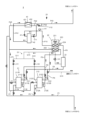
- Fig. 2 is a diagram showing a schematic configuration of a refrigeration unit 20.
- the refrigeration device 1 includes four refrigeration units 20_1 to 20_4, a cooling unit 50, a connection unit 60, and a control unit 70.
- the four freezing units 20_1 to 20_4 are arranged in parallel in the refrigeration cycle. Note that, in this embodiment, an example in which the refrigeration device 1 is equipped with four freezing units 20_1 to 20_4 is described, but the refrigeration device of the present disclosure may be equipped with multiple (N) freezing units. In other words, the number of freezing units equipped in the refrigeration device may be two, three, five or more.
- one of the four freezer units will be referred to as 20_1, the freezer unit arranged adjacent to freezer unit 20_1 will be referred to as 20_2, the freezer unit arranged further adjacent to freezer unit 20_2 will be referred to as 20_3, and the freezer unit arranged further adjacent to freezer unit 20_3 will be referred to as 20_4.
- the four freezer units 20_1 to 20_4 each have the same configuration.
- the suffixes "_1", “_2", “_3”, and “_4" may be omitted.
- FIG. 2 which illustrates the configuration common to the four freezer units 20_1 to 20_4, the suffixes are omitted.
- the refrigeration unit 20 includes a compression section 21, a heat dissipation heat exchanger 22, an oil separator 23, a pressure reducing valve 41, an intermediate cooler 42, and a split heat exchanger 43.
- the refrigeration device 1 includes four pressure reducing valves, the same number as the refrigeration units.
- the compression section 21 includes a first compressor 211 and a second compressor 212.
- the first compressor 211 and the second compressor 212 are arranged in parallel in a refrigeration cycle.
- the compression section 21 may include one compressor or three or more compressors. When the compression section 21 includes three or more compressors, the three or more compressors are arranged in parallel in a refrigeration cycle. Since the first compressor 211 and the second compressor 212 have a similar configuration, the first compressor 211 will be described in detail and the second compressor 212 will be described briefly.
- the first compressor 211 has a sealed container.
- the sealed container is formed with a first low-stage suction port 211A, a first low-stage discharge port 211B, a first high-stage suction port 211C, and a first high-stage discharge port 211D.
- the first low-stage suction port 211A is connected to the evaporator of the cooling unit 50 via a pipe P1.
- the first low-stage discharge port 211B is connected to the intercooler 222 of the heat dissipation heat exchanger 22 via a pipe P2.
- the first high-stage suction port 211C is connected to the intercooler 222 via a pipe P3.
- the first high-stage discharge port 211D is connected to the oil separator 23 via a pipe P4.
- a check valve CV1 is arranged in the pipe P4 to prevent the refrigerant discharged from the first high-stage discharge port 211D from flowing back to the first high-stage discharge port 211D.
- first low-stage compression element Inside the sealed container of the first compressor 211, there are arranged a first low-stage compression element, a first high-stage compression element, and a first motor, none of which are shown in the figure.
- the first low-stage compression element and the first high-stage compression element rotate in synchronization with the rotation of the first motor.
- the first low-stage compression element pressurizes the low-pressure refrigerant sucked from the evaporator of the cooling unit 50 to an intermediate pressure via the pipe P1 and the first low-stage suction port 211A.
- the first low-stage compression element discharges the refrigerant pressurized to the intermediate pressure to the intercooler 222 via the first low-stage discharge port 211B and the pipe P2.
- the first high-stage compression element pressurizes the intermediate-pressure refrigerant sucked from the intercooler 222 to a high pressure via the first high-stage suction port 211C and the pipe P3.
- the first high-stage compression element discharges the refrigerant pressurized to the high pressure to the oil separator 23 via the first high-stage discharge port 211D and the pipe P4. In this way, the first compressor 211 compresses the refrigerant in two stages.
- the second compressor 212 has a sealed container in which a second low-stage suction port 212A, a second low-stage discharge port 212B, a second high-stage suction port 212C, and a second high-stage discharge port 212D are formed.
- the second low-stage suction port 212A is connected to the evaporator of the cooling unit 50 via a pipe P5 branched from the pipe P1.
- the second low-stage discharge port 212B is connected to the intercooler 222 via a pipe P6 branched from the pipe P2.
- the second high-stage suction port 212C is connected to the intercooler 222 via a pipe P7 branched from the pipe P3.
- the second high-stage discharge port 212D is connected to the oil separator 23 via a pipe P8 branched from the pipe P4.
- a check valve CV2 is disposed in the pipe P8.
- a second low-stage compression element Inside the sealed container of the second compressor 212, a second low-stage compression element, a second high-stage compression element, and a second motor (not shown) are arranged.
- the second low-stage compression element and the second high-stage compression element rotate in synchronization with the rotation of the second motor, thereby compressing the refrigerant in two stages.
- a first oil amount detection unit 211E that detects the amount of oil remaining in the sealed container is disposed in the sealed container of the first compressor 211.
- a second oil amount detection unit 212E that detects the amount of oil remaining in the sealed container is disposed in the sealed container of the second compressor 212.
- the first and second oil amount detection units 211E, 212E are, for example, configured with oil level switches, and output a signal corresponding to the detected amount of oil remaining to the control unit 70.
- the heat dissipation heat exchanger 22 includes a heat dissipation blower 221, an intercooler 222, and a gas cooler 223.
- the heat dissipation fan 221 cools the intercooler 222 and the gas cooler 223.
- the intercooler 222 cools the intermediate pressure refrigerant discharged from the first and second low stage compression elements of the first and second compressors 211, 212, and discharges it to the first and second high stage compression elements.
- the gas cooler 223 is connected to the oil separator 23 via a pipe P9.
- the gas cooler 223 is connected to the intermediate cooler 42 via a pipe P10.
- the gas cooler 223 cools the high-pressure refrigerant discharged from the oil separator 23 and discharges it to the intermediate cooler 42.
- An outside air temperature sensor 224 is disposed near the heat dissipation heat exchanger 22.
- the outside air temperature sensor 224 outputs a signal corresponding to the detection result of the outside air temperature to the control unit 70.
- the oil separator 23 is connected to the respective sealed containers of the first compressor 211 and the second compressor 212 via an oil return pipe Q1.
- the oil return pipe Q1 includes a main pipe Q10 having one end connected to the oil separator 23, a first branch pipe Q11 connecting the other end of the main pipe Q10 to the sealed container of the first compressor 211, and a second branch pipe Q12 connecting the other end of the main pipe Q10 to the sealed container of the second compressor 212.
- a connection pipe Q13 connected to the connecting unit 60 is connected between the oil separator 23 of the main pipe Q10 and the branch point of the first branch pipe Q11 and the second branch pipe Q12.
- the oil separator 23 separates and stores the oil contained in the high-pressure refrigerant discharged from the first and second high-stage compression elements of the first and second compressors 211 and 212.
- the oil separator 23 returns the stored oil to the first and second compressors 211 and 212 via the oil return pipe Q1.
- a first oil valve V1 is disposed in the first branch pipe Q11.
- a second oil valve V2 is disposed in the second branch pipe Q12.
- a return valve V3 is disposed in the main pipe Q10.
- the first oil valve V1, the second oil valve V2, and the return valve V3 are each constituted by, for example, an electric valve, and are opened and closed under the control of the control unit 70.
- the first oil valve V1, the second oil valve V2, and the return valve V3 may be valves whose opening degree can be controlled in multiple stages under the control of the control unit 70.
- the destination of the oil returned from the oil separator 23 is controlled by opening and closing the first oil valve V1, the second oil valve V2, and the return valve V3.
- opening and closing the return valve V3 prevents gas from flowing from the oil separator 23 into the oil return pipe Q1, for example, when the oil separator 23 is low on oil.
- a high-pressure sensor H1 is disposed in the pipe P10.
- the high-pressure sensor H1 outputs a signal corresponding to the pressure in the pipe P10 to the control unit 70.
- the pressure detected by the high-pressure sensor H1 is approximately the same as the pressure in the gas cooler 223 and the oil separator 23.
- the pressure reducing valve 41 is, for example, an electric valve.
- the pressure reducing valve 41 is disposed closer to the intermediate cooler 42 than the position of the high pressure sensor H1 in the pipe P10.
- the pressure reducing valve 41 reduces the pressure of the high pressure refrigerant discharged from the gas cooler 223 and discharges it into the upper part of the intermediate cooler 42.
- the lower part of the intermediate cooler 42 is connected to one end of the first flow path 431 of the split heat exchanger 43 via the pipe P41.
- the upper part of the intermediate cooler 42 is connected to one end of the second flow path 432 of the split heat exchanger 43 via the pipe P42.
- a gas return motor valve V11 is arranged in the pipe P42.
- the intermediate cooler 42 cools the refrigerant depressurized by the pressure reducing valve 41.
- the refrigerant liquefied by cooling (liquid refrigerant) is discharged to the first flow path 431 of the split heat exchanger 43 via the pipe P41.
- the refrigerant not liquefied by cooling (gas refrigerant) is discharged to the second flow path 432 of the split heat exchanger 43 via the pipe P42.
- the other end of the first flow path 431 of the split heat exchanger 43 is connected to the cooling unit 50 via a pipe P43.
- a pipe P44 branching off from the pipe P42 is connected to the middle of the pipe P43.
- a liquid return motorized valve V12 is disposed in the pipe P44.
- the other end of the second flow path 432 of the split heat exchanger 43 is connected to the pipe P3 via a pipe P45.
- the split heat exchanger 43 having such a configuration, when the liquid return motor valve V12 is open, most of the liquid refrigerant discharged from the intercooler 42 passes through the first flow path 431 and the pipe P43 and flows into the cooling unit 50, while the remaining liquid refrigerant passes through the pipes P44 and P42 and flows into the second flow path 432. The flow of the remaining liquid refrigerant into the second flow path 432 supercools the refrigerant passing through the first flow path 431 toward the evaporator of the cooling unit 50.
- the gas refrigerant discharged from the intercooler 42 passes through the pipes P42, the second flow path 432, and the pipes P45, P3, and P7, and is returned to the first and second high-stage compression elements of the first and second compressors 211 and 212.
- the cooling unit 50 is disposed, for example, in a showcase that is the object to be cooled by the refrigeration device 1. Pipes P43_1 to P43_4 extending from each of the refrigeration units 20_1 to 20_4 are connected to the cooling unit 50. Although not shown in the figure, the cooling unit 50 includes one or more pressure reducing valves and the same number of evaporators as the pressure reducing valves.
- the pressure reducing valve of the cooling unit 50 is, for example, an electric valve.
- the pressure reducing valve of the cooling unit 50 reduces the pressure of the refrigerant discharged from the split heat exchanger 43 of the freezing unit 20 and discharges it to the evaporator.
- the evaporator of the cooling unit 50 exchanges heat between the liquid refrigerant flowing in from the pressure reducing valve and the air around the evaporator to generate cooling air for cooling the object to be cooled.
- the refrigerant after heat exchange passes through pipes P1_1 to P1_4 and P5_1 to P5_4 and is returned to the first and second low-stage compression elements of the freezing units 20_1 to 20_4.
- connection unit 60 connects the oil separators 23_1 to 23_4 of the four refrigeration units 20_1 to 20_4 to each other.
- the connection unit 60 has a loop-shaped oil supply pipe 61, four oil supply valves 62_1 to 62_4, and four check valves 63_1 to 63_4.
- the oil supply pipe 61 connects the oil return pipes Q1_1 to Q1_4 of the refrigeration units 20_1 to 20_4 via the connection pipes Q13_1 to Q13_4. As described above, the oil return pipes Q1_1 to Q1_4 are connected to the oil separators 23_1 to 23_4, respectively, so the oil supply pipe 61 connects the oil separators 23_1 to 23_4 of the four refrigeration units 20_1 to 20_4 in parallel.
- the four oil supply valves 62_1 to 62_4 are provided in the same number as the four refrigeration units 20_1 to 20_4.
- the four oil supply valves 62_1 to 62_4 are provided on the oil supply pipe 61.
- the oil supply valves 62 are arranged between the oil return pipes Q1 of the refrigeration units 20 adjacent to each other. That is, the oil supply valve 62_1 is arranged between the oil return pipe Q1_1 of the refrigeration unit 20_1 and the oil return pipe Q1_2 of the refrigeration unit 20_2.
- the oil supply valve 62_2 is arranged between the oil return pipe Q1_2 of the refrigeration unit 20_2 and the oil return pipe Q1_3 of the refrigeration unit 20_3.
- the oil supply valve 62_3 is arranged between the oil return pipe Q1_3 of the refrigeration unit 20_3 and the oil return pipe Q1_4 of the refrigeration unit 20_4.
- the oil supply valve 62_4 is disposed between the oil return pipe Q1_4 of the refrigeration unit 20_4 and the oil return pipe Q1_1 of the refrigeration unit 20_1.
- the oil supply valve 62 is, for example, an electrically operated valve.
- Each of the four oil supply valves 62_1 to 62_4 controls the flow of oil in the oil supply pipe 61 by opening and closing under the control of the control unit 70, which will be described later.
- the four check valves 63_1 to 63_4 are provided in the same number as the four freezing units 20_1 to 20_4.
- the four check valves 63_1 to 63_4 are provided in the oil supply pipe 61.
- the check valve 63 is arranged in series with the oil supply valve 62 between the oil return pipes Q1 of the freezing units 20 adjacent to each other.
- the check valve 63_1 is arranged between the oil return pipe Q1_1 of the freezing unit 20_1 and the oil return pipe Q1_2 of the freezing unit 20_2.
- the check valve 63_2 is arranged between the oil return pipe Q1_2 of the freezing unit 20_2 and the oil return pipe Q1_3 of the freezing unit 20_3.
- the check valve 63_3 is arranged between the oil return pipe Q1_3 of the freezing unit 20_3 and the oil return pipe Q1_4 of the freezing unit 20_4.
- the check valve 63_4 is disposed between the oil return pipe Q1_4 of the refrigeration unit 20_4 and the oil return pipe Q1_1 of the refrigeration unit 20_1.
- the check valve 63 allows the oil pipe 61 to flow in either direction.
- the oil flows only clockwise through the oil pipe 61, but in this disclosure the oil may also flow in the opposite direction (counterclockwise) through the oil pipe.
- the control unit 70 controls the operation of the entire refrigeration device 1 by controlling the controllable components of the refrigeration device 1.
- the control unit 70 is composed of, for example, a processor or a microcontroller having a CPU (Central Processing Unit).
- the refrigeration device 1 includes one control unit 70, but the present disclosure is not limited to this.
- a control unit that controls refrigeration unit 20_1, a control unit that controls refrigeration unit 20_2, a control unit that controls refrigeration unit 20_3, and a control unit that controls refrigeration unit 20_4 may each be provided separately.
- the four control units may cooperate with each other to operate the entire refrigeration device 1.
- the oil supply valve 62_1 arranged between the freezing unit 20_1 and the freezing unit 20_2 may be controlled, for example, by the control unit that controls the freezing unit 20_1.
- the oil supply valve 62_2 arranged between the freezing unit 20_2 and the freezing unit 20_3 may be controlled, for example, by the control unit that controls the freezing unit 20_2.
- the oil supply valve 62_3 arranged between the freezing unit 20_3 and the freezing unit 20_4 may be controlled, for example, by the control unit that controls the freezing unit 20_3.
- the oil supply valve 62_4 arranged between the freezing unit 20_4 and the freezing unit 20_1 may be controlled, for example, by the control unit that controls the freezing unit 20_4.
- Control system of refrigeration device 1 The following describes a control system of the refrigeration device 1, including the control unit 70.
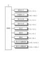
- Fig. 3 is a block diagram showing the control system of the refrigeration device 1.
- control unit 70 is configured to be able to transmit and receive various signals between the high pressure sensors H1_1-H1_4, the outside air temperature sensors 224_1-224_4, the first oil valves V1_1-V1_4, the second oil valves V2_1-V2_4, the return valves V3_1-V3_4, the pressure reducing valves 41_1-41_4, the oil supply valves 62_1-62_4, the first oil amount detection units 211E_1-211E_4, and the second oil amount detection units 212E_1-212E_4.
- the control unit 70 determines whether the amount of oil in the oil separator 23 is less than the first threshold value based on the detection results of the first oil amount detection unit 211E and the second oil amount detection unit 212E in each refrigeration unit 20.
- the first threshold is an example of a predetermined threshold of the present disclosure.
- the first threshold is the minimum amount of oil required in the oil separator 23 to supply sufficient oil to the first and second compressors 211 and 212.
- the first threshold is determined in advance based on the capacity of each of the first and second compressors 211 and 212, etc.
- the first threshold may also be determined in advance based on the initial value of the oil holding amount of each of the first and second compressors 211 and 212, or the initial value of the oil level position, etc.
- an oil level detection unit such as an oil level switch is provided in the compressor, but in the refrigeration system 1 disclosed herein, the amount of oil in the oil separator 23 is determined using the first and second oil level detection units 211E, 212E that are generally provided, so there is no need to provide the refrigeration system 1 with a new configuration to determine the amount of oil in the oil separator 23. Therefore, the amount of oil in the oil separator 23 can be determined at a relatively low cost.
- the control unit 70 also selectively controls the return valve V3 and oil supply valve 62 of each freezing unit 20 to perform a first control for circulating oil within each freezing unit 20, and a second control for supplying oil from within one of the freezing units to the other freezing unit.
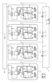
- FIG. 4 is a diagram for explaining the first control.
- FIG. 4 and FIG. 5 described later show only the main components, and the arrangement of the piping may differ from the example shown in FIG. 2.
- the suffixes "_1" to "_4" are omitted for the internal configuration of the refrigeration units 20_1 to 20_4.
- the pipes shown in solid lines are pipes through which oil, refrigerant, or a mixture of these flows.
- the pipes shown in dashed lines are pipes through which oil, refrigerant, or a mixture of these does not flow.
- when the figure showing the oil supply valve 62 is filled in it indicates that the valve is open, and when it is filled in, it indicates that the valve is closed.
- the control unit 70 opens the return valves V3 of all the refrigeration units 20 and closes all the oil supply valves 62 to drive the compression units 21. This allows oil to circulate between the first and second compressors 211, 212 and the oil separator 23 in each refrigeration unit 20, and restricts the movement of oil between the multiple refrigeration units 20 via the oil supply pipes 61.
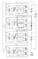
- FIG. 5 is a diagram for explaining the second control.
- the second control is a control for supplying oil from another freezing unit to a freezing unit in which the oil in the oil separator 23 falls below the first threshold.
- a freezing unit to which oil is supplied when the oil in the oil separator 23 falls below the first threshold is referred to as a "target unit.”
- FIG. 5 shows an example of the second control when freezing unit 20_3 is the target unit.
- FIG. 5 shows a case in which only one freezer unit 20_3 out of the four freezer units 20_1 to 20_4 is the target unit, but the present disclosure is not limited to this.
- the N e.g., four
- multiple units e.g., two or h is three
- the control unit 70 closes the return valve V3 of the target unit and opens the return valve V3 of the freezing units 20 other than the target unit.
- the control unit 70 then opens the oil supply valve 62_2, which is located between the oil return pipe Q1 of the target unit (freezing unit 20_3) and the oil return pipe Q1 of the freezing unit 20_2, which is located one upstream from the target unit in the oil flow direction allowed in the oil supply pipe 61, and controls to close the other oil supply valves.
- oil is replenished from the freezing unit 20_2, which is located one upstream from the target unit (freezing unit 20_3), to the target unit.
- the freezing unit that replenishes the target unit with oil may be referred to as a replenishment unit.
- the oil supply valve 62_2 located between the target unit, refrigeration unit 20_3, and refrigeration unit 20_2, which is one unit upstream from refrigeration unit 20_3, is closed, and the other oil supply valves 62_1, 62_3, and 62_4 are maintained in an open state.
- oil flows from the oil separator 23 of the compensation unit (refrigeration unit 20_2 in the example shown in FIG. 5) through the oil return pipe Q1 and connecting pipe Q13 to the oil supply pipe 61. Then, through the connecting pipe Q13 and oil return pipe Q1 of the target unit, the oil is supplied to the first compressor 211 and second compressor 212 of the target unit. In this way, the target unit is compensated for with oil.
- the check valve 63_2 allows the oil to flow in one direction through the oil supply pipe 61. Therefore, the oil that flows into the oil supply pipe 61 from the compensation unit (refrigeration unit 20_2) flows in one direction (clockwise in the example shown in FIG. 5) through the oil supply pipe 61, passes through the oil supply valve 62_2, and flows into the oil return pipe Q1 of the target unit (refrigeration unit 20_3).
- freezing unit 20_1 and freezing unit 20_3 are the two target units
- freezing unit 20_2 and freezing unit 20_4 may be set as compensation units in the second control.
- the number of target units and compensation units does not have to be the same. For example, if the three target units are freezing units 20_1 to 20_3, only freezing unit 20_4 is the compensation unit. Also, if freezing unit 20_4 is the target unit, one to three of freezing units 20_1 to 20_3 may be the compensation units. Even in these cases, the second control allows the compensation unit to compensate for oil to the target units.
- the refrigeration unit 20 one unit upstream from the target unit is used as the compensation unit, but the present disclosure is not limited to this. At least one of the refrigeration units 20 other than the target unit may be used as the compensation unit.
- the target unit is, for example, refrigeration unit 20_2
- oil can be replenished via the oil supply pipe 61 even if the compensation unit is refrigeration unit 20_3, which is one unit downstream from refrigeration unit 20_2, rather than refrigeration unit 20_1, which is one unit upstream from refrigeration unit 20_2.
- the control unit 70 opens all of the oil valves 62 installed in the oil supply pipe 61 between the oil return pipe Q1 of the target unit and the oil return pipe Q1 of the compensation unit. For example, if the freezing unit 20_1 is the target unit and the freezing unit 20_3 is the compensation unit, the control unit 70 opens both of the oil supply valves 62_3 and 62_4 installed between the connection point between the oil return pipe Q1 of the freezing unit 20_1 and the oil supply pipe 61 to the connection point between the oil return pipe Q1 of the freezing unit 20_3 and the oil supply pipe 61. This makes it possible to supply oil from the compensation unit to the target unit even if the target unit and the compensation unit are not adjacent to each other.
- the reason for performing the second control will be explained.
- the refrigerant containing oil hereinafter, sometimes referred to as “oil-containing refrigerant”
- oil-containing refrigerant passes from the compression section 21 of each freezing unit 20 through the oil separator 23, the gas cooler 223, and the pressure reducing valve 41, is supplied to the cooling unit 50, and then returns to the compression section 21 of each freezing unit 20.
- the amount of oil-containing refrigerant returning to the compression section 21 of each freezing unit 20 is approximately the same, the amount of oil circulating through each freezing unit 20 in the first control will be approximately the same.
- the amount of oil separated by the oil separator 23 of each freezing unit 20 will be approximately the same.
- the amount of oil in the oil separator 23 of each freezing unit 20 will be equal to or greater than the first threshold.
- the first threshold value is set to a value that allows the amount of oil in the first and second compressors 211, 212 to be equal to or greater than the second threshold value by returning the oil stored in the oil separator 23 to the first and second compressors 211, 212.
- the second threshold is the minimum amount of oil required in the first and second compressors 211 and 212.
- the amount of oil in the oil separator 23 may fall below the first threshold, resulting in a refrigeration unit 20 in which the amount of oil in at least one of the first and second compressors 211, 212 cannot be increased to or above the second threshold.
- the second control is performed to prevent such malfunctions from occurring.
- FIG. 6 is a flowchart for explaining an example of the operation of the refrigeration device 1.
- FIG. 6 is a flowchart showing the operation of the refrigeration device.
- step S1 the control unit 70 starts the first control, for example, based on a user operation (step S1).
- the control unit 70 opens the return valves V3 of all the refrigeration units 20, closes all the oil supply valves 62, and starts the operation of the compression units 21 of each refrigeration unit 20, as described above (see FIG. 4).
- the oil separated from the refrigerant by the oil separator 23 is stored in the oil separator 23.
- the control unit 70 supplies the oil in the oil separator 23 to the first and second compressors 211 and 212 so that the amount of oil in both the first and second compressors 211 and 212 is equal to or greater than the second threshold.
- the control unit 70 keeps the first oil valve V1 open (maximum opening) until the amount of oil in the first compressor 211 is equal to or greater than the second threshold, and closes the first oil valve V1 (sets the opening to 0) when the amount of oil in the first compressor 211 is equal to or greater than the second threshold.
- the pressure in the oil separator 23 is higher than the pressure at the part of the first compressor 211 where the oil flows in, the oil in the oil separator 23 is supplied to the first compressor 211 due to the pressure difference.
- the refrigerant that has passed through the oil separator 23 is depressurized by the pressure reducing valve 41 and used to generate cooling air in the cooling unit 50.
- control unit 70 controls the pressure reducing valve 41 so that the pressure inside the oil separator 23 becomes a target high pressure value based on the outside air temperature, based on the detection result of the outside air temperature sensor 224. Specifically, the control unit 70 controls the pressure reducing valve 41 so that the higher the outside air temperature, the higher the pressure detected by the high pressure sensor H1.
- step S2 the control unit 70 determines whether or not the amount of oil in the oil separator 23 of any of the four refrigeration units 20 is less than the first threshold. As described above, the control unit 70 estimates (determines) that the amount of oil in the oil separator 23 is less than the first threshold when, for example, the amount of oil in at least one of the first compressor 211 and the second compressor 212 remains less than the second threshold for a predetermined period of time or more.
- step S3 the control unit 70 starts the second control.
- the control unit 70 closes the return valve V3 of the target unit, opens the return valves V3 of the refrigeration units 20 other than the target unit, and opens all oil supply valves 62 installed in the oil supply pipe 61 between the oil return pipe Q1 of the target unit and the oil return pipe Q1 of the compensation unit, while keeping the other oil supply valves 62 closed.
- the amount of oil in the oil separator 23 decreases to below the first threshold, which can cause gaseous refrigerant to flow through the oil return pipe Q1 into the compression section 21.
- the return valve V3 provided in the oil return pipe Q1 is closed to prevent the refrigerant from flowing into the compression section 21.
- the control unit 70 may control the pressure reducing valve 41 of each refrigeration unit 20 so that the pressure in the oil separator 23 of the target unit is lower than the pressure in the oil separator 23 of the compensation unit.
- control unit 70 may further perform control in the second control to make the opening degree of the first oil valve V1 and the second oil valve V2 in the compensation unit lower than the opening degree in the first control.
- the opening degree of the first oil valve V1 and the second oil valve V2 can be controlled to three levels: “100” (opening degree when the valve is fully opened), “0" (opening degree when the valve is closed), and “50" (intermediate opening degree between fully opened and closed).
- the control unit 70 controls the opening degree of the first oil valve V1 and the second oil valve V2 in the compensation unit during the second control to "50". Note that it is desirable to maintain the opening degree of the first oil valve V1 and the second oil valve V2 of the target unit at "100".
- This type of control allows the oil from the oil separator 23 in the compensation unit to flow more easily to the target unit than to the compression section 21 of the compensation unit.
- step S4 the control unit 70 determines whether the amount of oil in all compressors (first and second compressors 211, 212) of all refrigeration units 20 has reached or exceeded the second threshold value based on the detection results of the first and second oil amount detection units 211E, 212E of each refrigeration unit 20.
- control unit 70 determines that the amount of oil in all compressors of all refrigeration units 20 is not equal to or greater than the second threshold (step S4: NO), it performs the process of step S4 again after a predetermined period of time has elapsed.
- step S4 YES
- the control unit 70 determines that the amount of oil in all compressors of all refrigeration units 20 is equal to or greater than the second threshold (step S4: YES)
- it ends the second control returns operation to step S1, and resumes the first control.
- control unit 70 determines that there is no target unit in which the amount of oil in the oil separator 23 is less than the first threshold (step S2: NO), the control unit 70 returns the operation to step S1 and continues the first control.
- the refrigeration device 1 comprises N (N is an integer of 3 or more) refrigeration units 20 each having a compressor (first compressor 211, second compressor 212), an oil separator 23, and an oil return pipe Q1 that returns the oil separated from the refrigerant by the oil separator 23 to the first compressor 211 and the second compressor 212, an oil supply pipe 61 that connects the oil return pipes Q1 of the N refrigeration units 20, and an oil return pipe Q1 that is disposed between the oil return pipes Q1 of the adjacent refrigeration units 20 in the oil supply pipe 61.
- N is an integer of 3 or more
- N oil supply valves 62 are provided to control the flow of oil in the oil supply pipe 61, and when it is determined that the amount of oil in the oil separator 23 of at least one of the N refrigeration units 20 is less than a predetermined threshold, control is performed to open all oil supply valves 62 arranged in the oil supply pipe 61 between the oil return pipe Q1 of at least one of the refrigeration units (compensating units) other than the refrigeration unit (target unit) determined to have an oil amount less than the predetermined threshold, and the oil return pipe Q1 of the target unit, and to close the other oil supply valves 62.
- the target unit when there is a target unit among the N refrigeration units 20 in which the amount of oil in the oil separator 23 is less than the amount (first threshold) that can supply sufficient oil to the first and second compressors 211, 212, the target unit can be replenished with oil from the replenishment unit via the oil supply pipe 61 and the oil supply valve 62. This makes it possible to avoid malfunctions (such as breakdowns) that may occur due to a lack of oil in the first and second compressors 211, 212 of the target unit.
- the oil supply pipe 61 allows oil to flow in one direction
- the control unit 70 performs control to open the oil supply valve 62 located between the target unit and the refrigeration unit 20 that is one unit upstream in the oil flow allowed by the oil supply pipe 61 as viewed from the target unit, and to close the other oil supply valve 62.
- the refrigeration unit 20 closest to the refrigeration unit 20 to be replenished with oil in the oil flow direction of the oil supply pipe 61 and one unit upstream can be used as the replenishment unit. This allows the target unit to be reliably replenished with oil, and also shortens the time required for oil to be replenished from the replenishment unit to the target unit.
- each refrigeration unit 20 further has a return valve V3 provided in the oil return pipe Q1, and the control unit 70 performs control to close the return valve V3 of the refrigeration unit 20 (target unit) in which the amount of oil in the oil separator 23 is determined to be less than the first threshold value.
- each refrigeration unit 20 further has a pressure reducing valve 41 that reduces the pressure of the refrigerant separated by the oil separator 23, and the control unit 70 controls the pressure reducing valve 41 of each refrigeration unit 20 so that the pressure in the oil separator 23 of the target unit is lower than the pressure in the oil separator 23 of the compensation unit.
- the oil supply pipe 61 allows oil to flow in one direction, but the present disclosure is not limited to this.
- the oil supply pipe of the present disclosure may allow oil to flow in either direction.
- the control unit opens the oil supply valve provided in the oil supply pipe, and oil is supplied from one of the other refrigeration units due to the pressure difference to a refrigeration unit in which the amount of oil in the oil separator is small and the pressure in the oil separator is low.
- the control unit controls the direction of oil flow permitted by the oil supply valve, and oil is preferably supplied between the refrigeration units.
- the oil supply pipe 61 does not have to be a looped pipe.
- the oil supply pipe of the present disclosure may be, for example, a straight pipe. Even in such a case, the oil supply valve between the target unit and the compensation unit is opened. Oil is supplied from the compensation unit to the target unit.
- the target unit may be any unit other than the compensation unit.
- the refrigeration unit with the largest amount of oil remaining in its oil separator may be the compensation unit.
- oil may be supplied from multiple compensation units to one target unit. Also, the number of target units does not have to be one.
- the control unit 70 estimates (determines) the amount of oil in the oil separator 23 based on the detection results of the first and second oil amount detection units 211E, 212E provided in the first and second compressors 211, 212.
- a detection unit that detects the amount of oil in each oil separator 23 may be disposed, and the control unit 70 may determine whether the amount of oil in each oil separator 23 is less than the first threshold value based on the detection results of the detection unit.
- the connecting unit 60 has an oil supply pipe 61, an oil supply valve 62, and a check valve 63, but at least one of the oil supply valve 62 and the check valve 63 may be included in any one of the N refrigeration units 20.
- a control unit 70 is provided to control the operation of the entire refrigeration device 1.
- an independent control unit may be provided for each of the N refrigeration units 20, for example.
- the control units provided for each of the N refrigeration units 20 communicate with each other and operate in cooperation with each other, or one of the control units mainly controls the other control units, thereby performing the same operation as in the above-described embodiment.
- the oil supply valve 62_1 provided between the refrigeration units 20_1 and 20_2 may be controlled, for example, by a control unit provided in the refrigeration unit 20_1, or by a control unit provided in the refrigeration unit 20_2.
- each of the four freezing units 20 has a split heat exchanger 43.
- only one split heat exchanger may be provided for multiple freezing units.
- the piping extending from the gas cooler of each freezing unit may be connected to one split heat exchanger.
- This disclosure can be applied to refrigeration equipment.
Landscapes
- Engineering & Computer Science (AREA)
- Physics & Mathematics (AREA)
- Mechanical Engineering (AREA)
- Thermal Sciences (AREA)
- General Engineering & Computer Science (AREA)
- Devices That Are Associated With Refrigeration Equipment (AREA)
Abstract
Un dispositif de réfrigération selon la présente divulgation est pourvu d'une unité de commande qui, s'il est déterminé qu'une quantité d'huile d'un séparateur d'huile d'au moins l'une des N unités de réfrigération est inférieure à un seuil prédéterminé, effectue une commande pour ouvrir toutes les vannes de remplissage d'huile disposées dans un tuyau de remplissage d'huile entre un tuyau de retour d'huile d'au moins l'une des unités de réfrigération autres que l'unité de réfrigération dans laquelle la quantité d'huile a été déterminée comme étant inférieure au seuil prédéterminé et le tuyau de retour d'huile de l'unité de réfrigération dans laquelle il a été déterminé que la quantité d'huile est inférieure au seuil prédéterminé et pour fermer les autres vannes de remplissage d'huile.
Priority Applications (1)
| Application Number | Priority Date | Filing Date | Title |
|---|---|---|---|
| JP2025537352A JPWO2025028362A1 (fr) | 2023-08-03 | 2024-07-24 |
Applications Claiming Priority (2)
| Application Number | Priority Date | Filing Date | Title |
|---|---|---|---|
| JP2023127064 | 2023-08-03 | ||
| JP2023-127064 | 2023-08-03 |
Publications (1)
| Publication Number | Publication Date |
|---|---|
| WO2025028362A1 true WO2025028362A1 (fr) | 2025-02-06 |
Family
ID=94395282
Family Applications (1)
| Application Number | Title | Priority Date | Filing Date |
|---|---|---|---|
| PCT/JP2024/026467 Pending WO2025028362A1 (fr) | 2023-08-03 | 2024-07-24 | Dispositif de réfrigération et procédé de commande |
Country Status (2)
| Country | Link |
|---|---|
| JP (1) | JPWO2025028362A1 (fr) |
| WO (1) | WO2025028362A1 (fr) |
Citations (8)
| Publication number | Priority date | Publication date | Assignee | Title |
|---|---|---|---|---|
| JPH01173686A (ja) | 1987-12-28 | 1989-07-10 | Omron Tateisi Electron Co | 波長可変型半導体レーザ |
| JPH0217763A (ja) | 1988-07-06 | 1990-01-22 | Ricoh Co Ltd | ファクシミリ装置 |
| JP2001124388A (ja) * | 1999-10-29 | 2001-05-11 | Sanyo Electric Co Ltd | 空気調和装置 |
| JP2001336840A (ja) * | 2000-05-30 | 2001-12-07 | Sanyo Electric Co Ltd | 空気調和装置 |
| US20110155816A1 (en) * | 2009-12-24 | 2011-06-30 | Jeong Hojong | Air Conditioner |
| JP2013204927A (ja) * | 2012-03-28 | 2013-10-07 | Toshiba Carrier Corp | 冷凍装置 |
| JP2023117097A (ja) * | 2022-02-10 | 2023-08-23 | パナソニックIpマネジメント株式会社 | 冷凍装置 |
| JP2023127064A (ja) | 2022-03-01 | 2023-09-13 | プライムプラネットエナジー&ソリューションズ株式会社 | 電池モジュール |
-
2024
- 2024-07-24 JP JP2025537352A patent/JPWO2025028362A1/ja active Pending
- 2024-07-24 WO PCT/JP2024/026467 patent/WO2025028362A1/fr active Pending
Patent Citations (8)
| Publication number | Priority date | Publication date | Assignee | Title |
|---|---|---|---|---|
| JPH01173686A (ja) | 1987-12-28 | 1989-07-10 | Omron Tateisi Electron Co | 波長可変型半導体レーザ |
| JPH0217763A (ja) | 1988-07-06 | 1990-01-22 | Ricoh Co Ltd | ファクシミリ装置 |
| JP2001124388A (ja) * | 1999-10-29 | 2001-05-11 | Sanyo Electric Co Ltd | 空気調和装置 |
| JP2001336840A (ja) * | 2000-05-30 | 2001-12-07 | Sanyo Electric Co Ltd | 空気調和装置 |
| US20110155816A1 (en) * | 2009-12-24 | 2011-06-30 | Jeong Hojong | Air Conditioner |
| JP2013204927A (ja) * | 2012-03-28 | 2013-10-07 | Toshiba Carrier Corp | 冷凍装置 |
| JP2023117097A (ja) * | 2022-02-10 | 2023-08-23 | パナソニックIpマネジメント株式会社 | 冷凍装置 |
| JP2023127064A (ja) | 2022-03-01 | 2023-09-13 | プライムプラネットエナジー&ソリューションズ株式会社 | 電池モジュール |
Also Published As
| Publication number | Publication date |
|---|---|
| JPWO2025028362A1 (fr) | 2025-02-06 |
Similar Documents
| Publication | Publication Date | Title |
|---|---|---|
| EP2495512B1 (fr) | Dispositif à cycle de réfrigération | |
| JP4360203B2 (ja) | 冷凍装置 | |
| JP5932971B2 (ja) | 冷凍装置及び冷凍サイクル装置 | |
| KR20130050700A (ko) | 비공비 혼합냉매를 이용한 냉장고 및 그 제어방법 | |
| JP7150148B2 (ja) | 室外ユニット、冷凍サイクル装置および冷凍機 | |
| US12410942B2 (en) | Heat source unit and refrigeration apparatus | |
| JP5764734B2 (ja) | 冷凍装置 | |
| KR20210075922A (ko) | 냉장고 | |
| EP2314954B1 (fr) | Réfrigérateur | |
| KR102237596B1 (ko) | 냉장고 및 그 제어방법 | |
| WO2011072679A1 (fr) | Système de compression de vapeur ayant un évaporateur divisé | |
| WO2025028362A1 (fr) | Dispositif de réfrigération et procédé de commande | |
| JP6835176B1 (ja) | 冷凍装置 | |
| JP7668467B2 (ja) | 冷凍装置 | |
| US20050150246A1 (en) | Refrigerating equipment | |
| WO2025028243A1 (fr) | Dispositif de réfrigération et procédé de commande | |
| JP5764736B2 (ja) | 冷凍装置 | |
| JP5764735B2 (ja) | 冷凍装置 | |
| US20170276416A1 (en) | Refrigeration apparatus | |
| KR100743753B1 (ko) | 냉장고 및 냉장고의 제어 방법 | |
| CN118140103A (zh) | 制冷循环装置 | |
| KR102246351B1 (ko) | 냉장고 | |
| JPH0480555A (ja) | 冷凍装置 | |
| JP7832513B2 (ja) | 空気調和装置 | |
| US20230251004A1 (en) | Refrigeration apparatus |
Legal Events
| Date | Code | Title | Description |
|---|---|---|---|
| 121 | Ep: the epo has been informed by wipo that ep was designated in this application |
Ref document number: 24849017 Country of ref document: EP Kind code of ref document: A1 |
|
| ENP | Entry into the national phase |
Ref document number: 2025537352 Country of ref document: JP Kind code of ref document: A |
|
| WWE | Wipo information: entry into national phase |
Ref document number: 2024849017 Country of ref document: EP |
|
| NENP | Non-entry into the national phase |
Ref country code: DE |