WO2025028145A1 - 波動伝播速度計測方法、波動伝播速度計測装置及びプログラム - Google Patents
波動伝播速度計測方法、波動伝播速度計測装置及びプログラム Download PDFInfo
- Publication number
- WO2025028145A1 WO2025028145A1 PCT/JP2024/024159 JP2024024159W WO2025028145A1 WO 2025028145 A1 WO2025028145 A1 WO 2025028145A1 JP 2024024159 W JP2024024159 W JP 2024024159W WO 2025028145 A1 WO2025028145 A1 WO 2025028145A1
- Authority
- WO
- WIPO (PCT)
- Prior art keywords
- propagation velocity
- propagation
- wave
- unit
- shape model
- Prior art date
- Legal status (The legal status is an assumption and is not a legal conclusion. Google has not performed a legal analysis and makes no representation as to the accuracy of the status listed.)
- Pending
Links
Images










Classifications
-
- G—PHYSICS
- G01—MEASURING; TESTING
- G01H—MEASUREMENT OF MECHANICAL VIBRATIONS OR ULTRASONIC, SONIC OR INFRASONIC WAVES
- G01H5/00—Measuring propagation velocity of ultrasonic, sonic or infrasonic waves, e.g. of pressure waves
-
- G—PHYSICS
- G01—MEASURING; TESTING
- G01N—INVESTIGATING OR ANALYSING MATERIALS BY DETERMINING THEIR CHEMICAL OR PHYSICAL PROPERTIES
- G01N29/00—Investigating or analysing materials by the use of ultrasonic, sonic or infrasonic waves; Visualisation of the interior of objects by transmitting ultrasonic or sonic waves through the object
- G01N29/04—Analysing solids
- G01N29/07—Analysing solids by measuring propagation velocity or propagation time of acoustic waves
-
- G—PHYSICS
- G01—MEASURING; TESTING
- G01N—INVESTIGATING OR ANALYSING MATERIALS BY DETERMINING THEIR CHEMICAL OR PHYSICAL PROPERTIES
- G01N29/00—Investigating or analysing materials by the use of ultrasonic, sonic or infrasonic waves; Visualisation of the interior of objects by transmitting ultrasonic or sonic waves through the object
- G01N29/44—Processing the detected response signal, e.g. electronic circuits specially adapted therefor
Definitions
- the present invention relates to a wave propagation velocity measuring method, a wave propagation velocity measuring device, and a program.
- a method for evaluating the mechanical properties of an object involves measuring the propagation speed of elastic waves, which have a high correlation with the mechanical properties from the standpoint of the object's degree of freedom and operational safety.
- Patent Document 1 describes an elastic wave inspection system that irradiates an elastic wave onto a test object and measures the propagation velocity of the elastic wave from the propagation time.
- Patent Document 2 describes an elastic constant measurement device that propagates elastic waves onto a plate to be measured from each direction, calculates multiple propagation velocities, and calculates the elastic constant of the plate to be measured based on the multiple propagation velocities.
- Patent Document 1 measures the propagation speed in multiple directions to reduce measurement variation, but since the propagation speeds measured in multiple directions are arithmetically averaged, materials with acoustic anisotropy cannot be evaluated.
- Patent Document 2 makes it possible to measure the elastic modulus in each direction for materials with acoustic anisotropy, but it has the problem that it requires elastic waves with different properties, such as longitudinal waves and transverse waves, to propagate in different directions, making the measurement time-consuming.
- the present invention has been made in consideration of the above circumstances. Its purpose is to provide a wave propagation velocity measurement method, a wave propagation velocity measurement device, and a program that can more easily measure the propagation velocity of elastic waves in a specified direction in an object having acoustic anisotropy.
- the present invention provides a method for measuring wave propagation velocity, comprising: A transmitter disposed on a first surface of an object having acoustic anisotropy transmits an elastic wave to the first surface; A receiving unit disposed on a first surface of the object or a second surface opposite to the first surface receives a plurality of the elastic waves propagating at different angles within the object, thereby acquiring a plurality of pieces of reception information; Calculating a plurality of propagation velocity vectors based on the plurality of received information; determining a propagation wavefront shape model corresponding to the acoustic anisotropy of the object based on the plurality of propagation velocity vectors; A wave propagation velocity measuring method for calculating a horizontal propagation velocity parallel to the first surface based on the propagation wavefront shape model.
- the invention described in claim 2 is the wave propagation velocity measuring method described in claim 1,
- Each of the plurality of pieces of received information includes information on a propagation time of the elastic wave propagating through the object,
- the plurality of propagation velocity vectors are calculated based on the plurality of pieces of reception information, a plurality of pieces of information on the arrangement intervals between the transmission unit and the reception unit in a direction parallel to the first surface, and a thickness information of the object.
- the invention described in claim 3 is the wave propagation velocity measuring method described in claim 1,
- the propagation wavefront shape model is calculated based on the plurality of propagation velocity vectors.
- the invention described in claim 4 is the wave propagation velocity measuring method described in claim 1,
- the propagation wavefront shape model is selected from a plurality of propagation wavefront shape model candidates based on the plurality of propagation velocity vectors.
- the invention described in claim 5 is the wave propagation velocity measuring method described in claim 2,
- the thickness information of the object is a tentative thickness value that is a tentative length in the thickness direction of the object, or a true thickness value that is a true length in the thickness direction of the object.
- the invention described in claim 6 is the wave propagation velocity measuring method described in claim 5, When the thickness information of the object is the true thickness value, In addition to the horizontal propagation velocity, a vertical propagation velocity perpendicular to the first surface is calculated.
- the invention described in claim 7 is the wave propagation velocity measuring method described in claim 2,
- the plurality of pieces of reception information are obtained by adjusting the distance between the transmitting unit and the receiving unit.
- the invention described in claim 8 is the wave propagation velocity measuring method described in claim 7,
- the distance between the transmitter and receiver is adjusted by selecting from a plurality of transmitting and/or receiving sensor elements that are pre-arranged at a predetermined position and/or shape.
- the invention described in claim 9 is the wave propagation velocity measuring method described in claim 1, arranging the transmitter and the receiver in an acoustic isotropy in-plane direction in which an object having uniaxial acoustic anisotropy exhibits acoustic isotropy, and calculating a first propagation velocity vector; Calculating a normal propagation velocity normal to the first surface based on the first propagation velocity vector; The transmitter and the receiver are disposed in an acoustic anisotropy plane direction in which the object exhibits acoustic anisotropy, and a second propagation velocity vector is calculated; A horizontal propagation velocity within the acoustic anisotropy plane is calculated based on the vertical propagation velocity, the second propagation velocity vector, and a propagation wavefront shape model corresponding to the acoustic anisotropy of the object.
- the invention described in claim 10 is the wave propagation velocity measuring method described in claim 1, changing the arrangement positions and/or arrangement directions of the transmitting unit and the receiving unit; The horizontal propagation velocity is measured for each of the installation positions and/or installation directions.
- the invention described in claim 11 is the wave propagation velocity measuring method described in claim 10, A horizontal propagation velocity corresponding to the placement position and/or placement direction is analyzed.
- the invention described in claim 12 is the wave propagation velocity measuring method described in claim 11, For each of the installation positions, statistical data including at least one of a maximum value, a minimum value, an average value, a variance value, and a principal component analysis result of the horizontal propagation velocity corresponding to the installation direction is obtained.
- the invention described in claim 13 is the wave propagation velocity measuring method described in claim 12, For each of the installation positions, an installation direction in which the horizontal propagation velocity exhibits a maximum value and/or a minimum value is derived.
- the invention described in claim 14 is the wave propagation velocity measuring method described in claim 10, The installation position and/or installation direction are displayed in association with the magnitude of the horizontal propagation velocity.
- the invention described in claim 15 is a wave propagation velocity measuring method according to any one of claims 1 to 14,
- the transmitting section and/or the receiving section has a plurality of acoustic elements integrally arranged in a line or matrix.
- the invention described in claim 16 is a wave propagation velocity measuring method according to any one of claims 1 to 14,
- the propagation wavefront shape model has an elliptical shape in the acoustic anisotropy plane of the object.
- the invention described in claim 17 is a wave propagation velocity measuring device, A transmitter disposed on a first surface of an object having acoustic anisotropy and configured to input an elastic wave to the first surface; A receiving unit that is disposed on a first surface of the object or a second surface opposite to the first surface, receives a plurality of the elastic waves propagating at different angles within the object, and outputs a plurality of pieces of received information; a propagation speed vector calculation unit that calculates a plurality of propagation speed vectors based on the plurality of pieces of received information; a propagation wavefront shape model determination unit that determines a propagation wavefront shape model corresponding to acoustic anisotropy of the object based on the plurality of propagation velocity vectors; a propagation velocity calculation unit that calculates a horizontal propagation velocity parallel to the first surface based on the propagation wavefront shape model.
- the invention according to claim 18 is a program, A transmitter disposed on a first surface of an object having acoustic anisotropy and configured to input an elastic wave to the first surface; A computer of a wave propagation velocity measuring device including a receiving unit disposed on a first surface of the object or a second surface opposite to the first surface, receiving a plurality of the elastic waves propagating at different angles within the object, and outputting a plurality of pieces of reception information, a propagation speed vector calculation unit that calculates a plurality of propagation speed vectors based on the plurality of pieces of received information; a propagation wavefront shape model determination unit that determines a propagation wavefront shape model corresponding to acoustic anisotropy of the object based on the plurality of propagation velocity vectors; The wavefront shape model is configured to function as a propagation velocity calculation unit that calculates a horizontal propagation velocity parallel to the first surface based on the propagation wavefront shape model.
- the present invention makes it easier to measure the propagation velocity of elastic waves in a specified direction in an object with acoustic anisotropy.
- FIG. 1 is a block diagram showing a configuration of a wave propagation velocity measuring device.
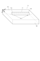
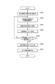
- FIG. 2 is a schematic perspective view showing the arrangement of a sensor element and an object of a wave propagation velocity measuring device. 4 is a flowchart showing a horizontal propagation velocity calculation method according to the first embodiment.
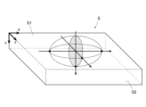
- FIG. 2 is a perspective conceptual diagram showing an acoustic anisotropy axis of an object according to the first embodiment.
- FIG. 2 is a schematic side view showing the arrangement of a sensor element and an object in a wave propagation velocity measuring device.
- FIG. 1 is a conceptual diagram of a wavefront shape model of an in-plane elastic wave propagation that exhibits acoustic anisotropy.
- FIG. 1 is a conceptual diagram of a wavefront shape model of an in-plane elastic wave propagation that exhibits acoustic anisotropy.
- FIG. 1 is a conceptual diagram of a wavefront shape model of an in-plane elastic wave propagation that exhibit
- FIG. 11 is a block diagram showing another configuration of the wave propagation velocity measuring device.
- 10 is a flowchart showing a horizontal propagation velocity calculation method according to a modified example of the first embodiment.
- 10 is a flowchart showing a horizontal propagation velocity calculation method according to a second embodiment.
- FIG. 13 is a schematic perspective view showing an arrangement of a sensor element and an object according to a modification of the first to fourth embodiments.
- FIG. 13 is a schematic side view showing an arrangement of a sensor element and a target object according to the modified examples of the first to fourth embodiments.
- FIG. 13 is a schematic perspective view showing an arrangement of a sensor element and an object whose orientation is set in a first direction according to a fifth embodiment.
- FIG. 13 is a schematic perspective view showing an arrangement of a sensor element and an object whose arrangement direction has been changed to a second direction according to the fifth embodiment.
- 13 is a flowchart showing a horizontal propagation velocity calculation method according to the fifth embodiment.
- FIG. 1 is a conceptual diagram of a wavefront shape model of a propagation wave of an elastic wave in a plane exhibiting acoustic isotropy.
- 13 is a flowchart showing a horizontal propagation velocity calculation method according to the sixth embodiment.
- 13 is a flowchart showing a horizontal propagation velocity calculation method according to a modification of the sixth embodiment.
- FIG. 2 is a perspective conceptual diagram of an object whose acoustic anisotropy axis is not parallel to a first surface.
- FIG. 1 is a conceptual diagram of a wavefront shape model of a propagation wave of an elastic wave in a plane exhibiting acoustic isotropy.
- 13 is a flowchart showing a horizontal propagation velocity
- FIG. 2 is a schematic side view of an object whose acoustic anisotropy axis is not parallel to a first surface.
- FIG. 23 is a schematic perspective view showing an arrangement of a sensor element and an object according to a modified example of the sixth embodiment.
- 1 is an example of a velocity map showing velocity data corresponding to the arrangement position of an array type sensor.
- 13 is another example of a velocity map showing velocity data corresponding to the arrangement positions of the array type sensor.
- 1 is an example of a velocity map showing velocity data corresponding to an arrangement direction of an array type sensor.
- Fig. 1 is a block diagram showing the functional configuration of a wave propagation velocity measuring device 100.
- the wave propagation velocity measuring device 100 includes a sensor unit 10 and a processing device 20, and measures the propagation velocity of an elastic wave in an object S.
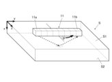
- Fig. 2 is a perspective view showing the arrangement of sensor elements 11 constituting the sensor unit 10 that propagates an elastic wave in the object S.
- elastic waves are waves that propagate through an elastic body, and include, for example, sound waves, seismic waves, etc.
- ultrasonic waves are used as elastic waves.
- the x direction, y direction, and z direction represent the directions shown in Figure 2.
- the object S is a material that exhibits acoustic anisotropy.
- Acoustic anisotropy is the property of the propagation speed of elastic waves varying depending on the direction of propagation.
- Materials that may have acoustic anisotropy include, for example, metals or metal alloys such as titanium (Ti) that contain a crystalline structure or are stretched in a specific direction, or composites that combine various fillers with a resin base material, such as carbon fiber reinforced plastics (CFRP), carbon fiber reinforced thermoplastics (CFRTP), or glass fiber reinforced plastics (GFRP).
- CFRP carbon fiber reinforced plastics
- CFRTP carbon fiber reinforced thermoplastics
- GFRP glass fiber reinforced plastics
- the object S is shown as being flat, but is not limited to this. However, it is preferable that the first surface S1 (yz surface) and the opposing second surface S2 are substantially parallel to each other, and the object S may be cylindrical, for example.
- the sensor unit 10 transmits and receives ultrasonic waves while in contact with the first surface S1 of the target object S.
- the sensor unit 10 includes a sensor element 11 and a drive unit 12.
- the sensor element 11 is an array type sensor consisting of a plurality of piezoelectric elements arranged one-dimensionally in a predetermined direction, for example as shown in Fig. 2.
- the transmitter 11a is selected from the sensor element 11, and transmits ultrasonic waves by vibrating according to a transmission signal output from a signal generating unit 22 (described later) of the processing device 20.
- the receiver 11b is selected from the sensor element 11, and receives the ultrasonic waves transmitted by the transmitter 11a, converts them into an electrical signal, and generates a received signal, which is input to the processing device 20.
- the driving unit 12 changes the arrangement position and arrangement direction of the sensor element 11.
- the driving unit 12 is a two-dimensional movement mechanism that moves the sensor element 11 to an arbitrary position on the first surface S1 of the target S, and a rotation mechanism that rotates the sensor element 11 in an arbitrary direction on the first surface S1.
- the processing device 20 is connected to the sensor unit 10 and controls the sensor unit 10.
- the sensor unit 10 and the processing device 20 may be connected by wire, for example, a cable and a connector, or may be connected wirelessly by wireless communication.
- the processing device 20 includes a control unit 21, a signal generating unit 22, a display unit 23, an operation input unit 24, a storage unit 25, etc.
- the control unit 21 includes a central processing unit (CPU), a random access memory (RAM), and a read only memory (ROM).
- the control unit 21 controls the overall operation of the wave propagation velocity measuring device 100.
- the CPU controls each part of the wave propagation velocity measuring device 100.
- the RAM is a volatile memory that temporarily stores various information in a writable and readable manner.
- the ROM is a non-volatile memory in which various information and programs are stored in a readable manner. More specifically, the control unit 21 reads out a specified program from the various programs stored in the ROM using the CPU and expands it into the RAM. The control unit 21 then executes various processes in cooperation with the expanded program.
- the control unit 21 functions as a propagation time measurement unit 21a that measures, for example, the propagation time, which is the time from when the transmitting unit 11a transmits an ultrasonic wave until the receiving unit 11b receives the ultrasonic wave, as reception information.
- the control unit 21 also functions as a transmission/reception interval adjustment unit 21b that selects the transmitting unit 11a and the receiving unit 11b from the sensor element 11 by supplying a signal to the sensor unit 10, and adjusts the arrangement interval between the transmitting unit 11a and the receiving unit 11b.
- the control unit 21 also functions as a propagation velocity vector calculation unit 21c that calculates a propagation velocity vector based on the propagation time of the ultrasonic wave, the arrangement interval between the transmitting unit 11a and the receiving unit 11b, and the thickness information of the object S.
- the control unit 21 also functions as a propagation wavefront shape model determination unit 21d that determines a propagation wavefront shape model of the ultrasonic wave in the object S based on the calculated propagation velocity vector.
- the control unit 21 also functions as a propagation velocity calculation unit 21e that calculates the propagation velocity of the ultrasonic wave in a predetermined direction of the object S based on the propagation wavefront shape model.
- the control unit 21 also functions as an analysis unit 21f that analyzes the propagation speed of ultrasonic waves corresponding to the installation position and/or installation direction of the transmission unit 11a and the reception unit 11b.
- the signal generating unit 22 under the control of the control unit 21, inputs a transmission signal, which is an electrical signal, to the transmitting unit 11a of the sensor unit 10, thereby transmitting ultrasonic waves to the target S from the transmitting unit 11a.
- the display unit 23 displays various information in a propagation velocity calculation process described later. In particular, the display unit 23 displays a velocity map described later.
- the display unit 23 includes a display panel such as an LCD (Liquid Crystal Display) or an organic EL (Electro-Luminescence) display.
- the operation input unit 24 is operated by a user who uses the processing device 20. In response to the operation, the operation input unit 24 inputs various information and instructions to the processing device 20.
- the operation input unit 24 is, for example, a mouse, a keyboard, and a push button.
- the storage unit 25 is configured with a hard disk drive (HDD) or a solid state drive (SSD) and stores various types of information in a readable and writable manner.
- HDD hard disk drive
- SSD solid state drive
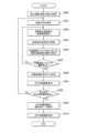
- the control unit 21 which has received operation input from the user via the operation input unit 24, acquires thickness information D relating to the thickness value of the target object S (step S100).
- the control unit 21 acquires the true thickness value, which is an actual measurement value, as the thickness information D from data previously stored in the memory unit 25 or from operation input from the user via the operation input unit 24.
- the control unit 21 After acquiring the thickness information D, the control unit 21, which is the transmission/reception interval adjustment unit 21b, sets the arrangement interval L1 in the y direction between the transmission unit 11a and the reception unit 11b (step S102). Specifically, the control unit 21 sets the arrangement interval L1 by selecting the sensor elements 11 that function as the transmission unit 11a and the reception unit 11b.
- the control unit 21 After setting the arrangement interval L1 , the control unit 21 inputs a transmission signal from the signal generating unit 22 to the transmitting unit 11a to transmit ultrasonic waves from the transmitting unit 11a, and receives the ultrasonic waves at the receiving unit 11b and outputs a reception signal (step S103). Then, the control unit 21, which is the propagation velocity vector calculation unit 21c, calculates the propagation velocity vector of the ultrasonic waves (step S104).
- the oblique propagation time from when an ultrasonic wave is transmitted from the transmitting unit 11a on the first surface S1 of the object S and reflected by the second surface S2 until the ultrasonic wave is received by the receiving unit 11b on the first surface S1 that is L1 away from the transmitting unit 11a is denoted as t1 .
- the control unit 21 calculates the magnitude Vc1 of the first propagation velocity vector from FIG. 4B using the following formula (1).
- the input angle of the ultrasonic wave transmitted from the transmitting unit 11a and input to the first surface S1 is calculated from FIG. 4B using the following formula (2).
- the control unit 21 determines whether or not a plurality of propagation velocity vectors have been calculated (step S105). If a plurality of propagation velocity vectors have not been calculated (step S105; No), the control unit 21 transitions to step S102 and changes the arrangement interval to L2 , which is different from L1 .
- the oblique propagation time from when an ultrasonic wave is transmitted from the transmitting unit 11a until the ultrasonic wave is received by the receiving unit 11b (11b') that is L2 away from the transmitting unit 11a is set to t2 .
- the control unit 21 calculates the magnitude Vc2 of the second propagation velocity vector of the ultrasonic wave that is input to the first surface S1 at an angle different from the first propagation velocity vector and propagates through the object S by the following formula (3), similar to formula (1).
- angle ⁇ 2 that the second propagation velocity vector makes with respect to the y-axis is calculated by the following formula (4), similarly to formula (2).
- control unit 21 which is the propagation wavefront shape model determination unit 21d, determines a propagation wavefront shape model of the ultrasonic waves propagating within the object S from the multiple propagation velocity vectors (step S106).
- the object S is an acoustically anisotropic material with one axis of anisotropy in the y direction.
- the wavefront of the ultrasonic waves propagating in the xy plane of the object S shows an elliptical shape or a shape similar thereto. Therefore, if the vertical propagation velocity (propagation velocity in the x direction) of the object S is Va and the horizontal propagation velocity is Vb, the multiple propagation velocity vectors calculated in steps S102 to S105 can be mapped onto the same propagation wavefront shape model expressed as an ellipse, as shown in FIG. 5. In other words, based on the first and second propagation velocity vectors, the propagation wavefront shape models expressed by the following mathematical expressions (5) and (6) are simultaneously established.
- the arrangement intervals L1 and L2 , the thickness information D, and the oblique propagation times t1 and t2 are all values obtained by actual measurement. Therefore, by substituting the formulas (1) and (2) into the formula (5) and the formulas (3) and (4) into the formula (6), the only unknown values among the variables included in the formulas (5) and (6) are the vertical propagation velocity Va and the horizontal propagation velocity Vb. Therefore, the horizontal propagation velocity Vb and the vertical propagation velocity Va can be calculated by simultaneously solving the formulas (5) and (6).
- the transmitting unit 11a arranged on the first surface S1 of the object S having acoustic anisotropy transmits an elastic wave to the first surface S1
- the receiving unit 11b arranged on the first surface S1 of the object S receives a plurality of elastic waves propagating at different angles within the object S, thereby acquiring a plurality of pieces of reception information.
- a plurality of propagation velocity vectors are calculated based on the plurality of reception information, a propagation wavefront shape model corresponding to the acoustic anisotropy of the object S is determined based on the plurality of propagation velocity vectors, and a horizontal propagation velocity Vb parallel to the first surface S1 is calculated based on the propagation wavefront shape model.
- the horizontal propagation velocity Vb in the y direction can be calculated without arranging the transmitting unit 11a and the receiving unit 11b opposite each other on both end surfaces parallel to the zx plane of the object S to propagate the ultrasonic wave in the y direction.
- the propagation velocity of the elastic wave in a predetermined direction can be measured more easily even for an object S having an elongated shape for which it is physically difficult to arrange a sensor on the end surface.
- the propagation wavefront shape model is arithmetically determined by substituting a plurality of propagation velocity vectors into the formulas (5) and (6), but the present invention is not limited to this. That is, as shown in FIG. 6, a plurality of candidates for the propagation wavefront shape model (hereinafter, referred to as propagation wavefront shape model candidates) corresponding to the object S are calculated in advance and stored in the storage unit 25. Then, an optimal propagation wavefront shape model may be selected based on the plurality of propagation velocity vectors expressed by the formulas (1) and (2) and the formulas (3) and (4). This can save the effort and cost of sequentially calculating the propagation wavefront shape model using the propagation velocity vectors, and can more efficiently calculate the horizontal propagation velocity Vb.
- multiple sensor elements 11 may be simultaneously selected as the transmission unit 11a, multiple ultrasonic waves may be simultaneously transmitted, and multiple reception signals may be obtained by receiving the ultrasonic waves with one reception unit 11b, thereby calculating multiple propagation velocity vectors. This eliminates the need to set the placement interval multiple times and transmit and receive ultrasonic waves multiple times, and makes it possible to calculate the horizontal propagation velocity Vb more efficiently.
- the control unit 21 acquires thickness information D relating to the thickness value of the target object S (step S1000).
- the control unit 21 transmits ultrasonic waves from the transmission unit 11a, receives ultrasonic waves at the reception unit 11b that is L1 away from the transmission unit 11a and the reception unit 11b (11b') that is L2 away from the transmission unit 11a, and outputs a plurality of reception signals (step S1003).
- control unit 21, which is the propagation velocity vector calculation unit 21c calculates a plurality of propagation velocity vectors based on the plurality of reception signals (step S1004).
- the control unit 21, which is the propagation wavefront shape model determination unit 21d determines a propagation wavefront shape model of the ultrasonic waves propagating in the target object S from the plurality of propagation velocity vectors (step S1006).
- the control unit 21, which is the propagation velocity calculation unit 21e calculates the horizontal propagation velocity Vb from the propagation wavefront shape model (step S1007).
- the control unit 21 transmits ultrasonic waves from the transmission unit 11a, receives the ultrasonic waves at the reception unit 11b, which is disposed at the same position as the transmission unit 11a and at a position L away from the transmission unit 11a, and measures the vertical propagation time ta and the diagonal propagation time tc. Then, by acquiring the thickness information D, the control unit 21 calculates the magnitude Vc of the propagation velocity vector and the input angle ⁇ according to the following formulas (7) and (8) based on formulas (1) and (2).
- the vertical propagation speed Va is calculated by the following formula (9) using the thickness information D and the vertical propagation time ta.
- the placement interval L, thickness information D, vertical propagation time ta, and diagonal propagation time tc are all values obtained by actual measurement. Therefore, when formulas (7) to (9) are substituted into formula (10), the only unknown value among the variables contained in formula (10) is the horizontal propagation velocity Vb, and by solving this, the horizontal propagation velocity Vb can be calculated.
- the control unit 21 which receives operation input from the user via the operation input unit 24, obtains the thickness information D of the target object S by setting a provisional thickness value (step S200).
- Steps S202 to S206 are substantially the same as steps S102 to S106 in FIG. 3, and therefore will not be described here.
- the control unit 21, which is the propagation velocity calculation unit 21e calculates the horizontal propagation velocity Vb (step S207).
- the thickness information D is an unknown value. Therefore, even if the formulas (1) and (2) and the values of L1 and t1 are substituted into the formula (5), and the formulas (3) and (4) and the values of L2 and t2 are substituted into the formula (6), the unknown values among the variables included in the formulas (5) and (6) are three, namely Va, Vb, and D, and the horizontal propagation velocity Vb cannot be calculated even if the formulas (5) and (6) are solved simultaneously.
- the vertical propagation time ta until the ultrasonic wave is received by the receiving unit 11b, which is disposed in the same position as the transmitting unit 11a, is further obtained, and the vertical propagation speed Va is calculated using formula (9).
- the unknown variables contained in formulas (5) and (6) are the horizontal propagation velocity Vb and the thickness information D. Therefore, similar to the case where the thickness information D is known, the horizontal propagation velocity Vb can be calculated by simultaneously solving formulas (5) and (6).
- the vertical propagation velocity Va is used as the new third propagation velocity vector, but this is not limited to this.
- the new third propagation velocity vector may be an ultrasonic propagation velocity vector having a predetermined input angle, similar to the first and second propagation velocity vectors.
- the propagation velocity of the elastic wave in a predetermined direction of the object S can be measured even if the thickness of the object S is unknown.
- control unit 21 measures a vertical propagation time ta and an oblique propagation time tc. Then, by setting a predetermined temporary thickness value Dp as thickness information, the control unit 21 calculates a magnitude Vcp of the propagation velocity vector corresponding to Dp , the input angle ⁇ p , and the vertical propagation velocity Vap by the following formulas (11 ) to (13) based on formulas (1), (2), and (9).
- control unit 21 sets a predetermined temporary thickness value Dq different from Dp as thickness information, and calculates the magnitude Vcq of the propagation velocity vector corresponding to Dq , the input angle ⁇ q , and the vertical propagation velocity Vaq by the following formulas (14) to (16) based on the formulas (3), (4), and (9).
- the propagation velocity vector (Vc p , ⁇ p ), the vertical propagation velocity Va p , and the horizontal propagation velocity V b corresponding to D p can be mapped onto the first propagation wavefront shape model.
- the propagation velocity vector (Vc q , ⁇ q ), the vertical propagation velocity Va q , and the horizontal propagation velocity V b corresponding to D q can be mapped onto the second propagation wavefront shape model. Therefore, the following formulas (17) and (18) are simultaneously satisfied.
- the horizontal propagation velocity Vb can be calculated by determining the value of Vb that simultaneously satisfies formulas (17) and (18).
- control unit 21 sets thickness information of the object to a predetermined value D3 , transmits ultrasonic waves from the transmitting unit 11a, and receives the ultrasonic waves with the receiving unit 11b disposed at a position L away from the transmitting unit 11a, thereby measuring the oblique propagation time t3 . Then, the control unit 21 calculates the magnitude Vc3 and the input angle ⁇ 3 of the first propagation velocity vector by the following formulas (19) and (20) based on formulas (1) and (2).
- control unit 21 sets the thickness information to a predetermined value D4 different from D3 , and measures the oblique propagation time t4 by transmitting ultrasonic waves from the transmitting unit 11a and receiving them with the receiving unit 11b. Then, the control unit 21 calculates the magnitude Vc4 and the input angle ⁇ 4 of the second propagation velocity vector by the following formulas (21) and (22) based on formulas (3) and (4).
- the first and second propagation velocity vectors can be mapped onto the same propagation wavefront shape model together with the vertical propagation velocity Va and the horizontal propagation velocity Vb. Therefore, the following equations (23) and (24) hold simultaneously.
- conditions under which the thickness information of the object S can be changed include when the object S is a deformable material such as a liquid, or when the object S is a solid material such as a metal, samples of different thicknesses can be prepared.
- the horizontal propagation velocity of the object S can be measured without changing the distance between the transmitter and the receiver of the ultrasonic wave.
- the sensor unit 10 is an array-type sensor configured by arranging a plurality of sensor elements 11 in a one-dimensional array, and the transmitter 11a and the receiver 11b are selected from the plurality of sensor elements 11, but this is not limited to the above.
- the sensor unit 10 may have a plurality of independent sensor elements 11, for example as shown in FIG. 9A, with the first sensor element 11 being the transmitter 11a and the second sensor element 11 being the receiver 11b.
- the control unit 21 sets the spacing and/or direction of the transmitter 11a and receiver 11b by moving the sensor element 11 corresponding to either the transmitter 11a or the receiver 11b, or both, using the two-dimensional movement mechanism of the drive unit 12.
- ultrasonic waves are transmitted from the transmitting unit 11a disposed on the first surface S1, and ultrasonic waves reflected by the second surface S2 are received by the receiving unit 11b, but this is not limited to the configuration.
- the receiving unit 11b may be disposed on the second surface S2, and ultrasonic waves that have passed through the target object S may be received.
- the object S has uniaxial acoustic anisotropy
- the two acoustic anisotropy axes are parallel to the first surface S1, and the axial direction is known.
- the horizontal propagation velocity Vb is calculated while changing the arrangement direction ⁇ of the transmitter 11a and the receiver 11b (sensor element 11) on the first surface S1 of the object S.
- the propagation speed calculation process according to the fifth embodiment will be explained using the flowchart in FIG. 11. Note that in this embodiment, the thickness of the target object S is unknown. In the following, detailed explanations of the contents common to FIG. 8 will be omitted and the differences will be mainly explained.
- the control unit 21 acquires a tentative thickness value as thickness information D of the object S (step S300).
- the control unit 21 controls the drive unit 12 to set the arrangement direction ⁇ of the sensor element 11 (step S301). Specifically, as shown in FIG. 10A, the control unit 21 sets the arrangement direction ⁇ of the sensor element 11 to the in-plane direction (z direction) in which the object S exhibits acoustic isotropy.
- control unit 21 receives a plurality of ultrasonic waves at different arrangement intervals L1 and L2 in one direction, and calculates the magnitudes Vc1 , Vc2 of a plurality of propagation velocity vectors in a cross section including the direction by using the formulas (1) and (3).
- the control unit 21 calculates the true thickness value of the object S (step S306).
- the wavefront shape of the ultrasonic wave propagating in the object S becomes a perfect circle as shown in Fig. 12. Therefore, the magnitudes Vc1 and Vc2 of the multiple propagation velocity vectors calculated by arranging the sensor elements 11 in the in-plane direction are all equal.
- the thickness information D of the target object S can be expressed by the following formula (25) based on formulas (1) and (3).
- the true thickness value D can be calculated by substituting the arrangement intervals L1 and L2 set in the isotropic in-plane direction of the target object S and the oblique propagation times t1 and t2 , which are actual measured values, into formula (25).
- control unit 21 measures the vertical propagation time ta and substitutes it into equation (9) together with the true thickness value D calculated in step S306 to calculate the vertical propagation speed Va (step S307).
- control unit 21 changes the arrangement direction ⁇ of the sensor element 11 by 90° using the drive unit 12 (step S308). That is, as shown in FIG. 10B, the control unit 21 sets the arrangement direction ⁇ of the sensor element 11 to the in-plane direction (y direction) in which the object S exhibits acoustic anisotropy.
- the subsequent steps S309 to S311 are substantially similar to steps S302 to S304, and therefore detailed description will be omitted. That is, the control unit 21 sets the placement interval L and transmits and receives ultrasonic waves, thereby calculating the magnitude Vc and the input angle ⁇ of one propagation velocity vector in a cross section including the direction using formulas (7) and (8).
- the control unit 21 determines a propagation wavefront shape model expressed by formula (10) (step S312).
- the control unit 21 calculates the horizontal propagation velocity Vb by substituting the magnitude Vc and the input angle ⁇ of the propagation velocity vector and the vertical propagation velocity Va calculated in step S307 into formula (10) (step S313).
- the transmitter 11a and the receiver 11b are arranged in the acoustic isotropy plane direction of the object S having uniaxial acoustic anisotropy to calculate a plurality of propagation velocity vectors, and the true thickness value of the object S and the vertical propagation velocity Va perpendicular to the first surface S1 are calculated based on the propagation velocity vectors.
- the transmitter 11a and the receiver 11b are arranged in the acoustic anisotropy plane direction of the object S to calculate a propagation velocity vector, and the horizontal propagation velocity Vb in the acoustic anisotropy plane is calculated based on the propagation velocity vector, the vertical propagation velocity Va, and a propagation wavefront shape model corresponding to the acoustic anisotropy of the object S.
- the horizontal propagation velocity Vb of the uniaxial anisotropic material but also the thickness information D and the vertical propagation velocity Va can be measured.
- the sensor element 11 is arranged in the acoustic isotropic in-plane direction of the object S, and the receiving unit 11b arranged at the same position as the transmitting unit 11a receives an ultrasonic wave once, measures the propagation time, and calculates the vertical propagation velocity Va.
- the object S is a material having uniaxial acoustic anisotropy, and the two axes of the acoustic anisotropy are parallel to the first surface S1 and the axial directions are known, that is, the surface direction showing acoustic isotropy is known.
- the direction of the acoustic anisotropy axes of the object S is unknown, that is, the surface direction showing acoustic isotropy is unknown.
- the propagation speed calculation process according to the sixth embodiment will be explained using the flowchart in FIG. 13. Note that in this embodiment, the thickness information of the target object S is assumed to be unknown. In the following, detailed explanations of the content common to FIG. 8 will be omitted, and the differences will be mainly explained.
- the control unit 21 acquires a tentative thickness value as thickness information D of the target object S (step S400).
- the control unit 21 controls the drive unit 12 to set the arrangement direction ⁇ of the sensor element 11 to a predetermined direction (step S401).
- the control unit 21 receives multiple ultrasonic waves at different arrangement intervals in a predetermined direction ⁇ , and calculates multiple propagation velocity vectors in a cross section including the direction ⁇ . Then, based on the multiple propagation velocity vectors, it calculates the horizontal propagation velocity Vh( ⁇ ) in the arrangement direction ⁇ .
- control unit 21 determines whether the horizontal propagation speed Vh( ⁇ ) in all directions within the desired measurement range has been calculated (step S408).
- step S408 If the horizontal propagation speed Vh( ⁇ ) in all directions in the desired measurement range has not been calculated (step S408; No), the process proceeds to step S401, where the installation direction ⁇ is changed and the horizontal propagation speed Vh( ⁇ ) is calculated again.
- control unit 21 analyzes the relationship between the multiple horizontal propagation velocities Vh( ⁇ ) and the placement position and placement direction ⁇ of the sensor element 11 corresponding to each horizontal propagation velocity Vh( ⁇ ).
- control unit 21, which is the analysis unit 21f, acquires statistical data of the horizontal propagation speed Vh( ⁇ ) corresponding to the installation direction ⁇ for each installation position of the sensor element 11 (step S409).
- the statistical data includes at least one of the maximum value, minimum value, average value, variance value, and principal component analysis result of the horizontal propagation speed Vh( ⁇ ).
- the control unit 21 After acquiring the statistical data of the horizontal propagation velocity Vh( ⁇ ), the control unit 21 determines the vertical propagation velocity Va and the horizontal propagation velocity Vb based on the statistical data.
- the propagation wavefront shape model in the cross section of the object S is elliptical, and the horizontal propagation velocity Vh( ⁇ ) with respect to the arrangement direction ⁇ also changes to show an ellipse.
- the vertical propagation velocity Va coincides with either the maximum or minimum value of the horizontal propagation velocity Vh( ⁇ )
- the horizontal propagation velocity Vb coincides with either the maximum or minimum value of the horizontal propagation velocity Vh( ⁇ ) that is different from the vertical propagation velocity Va. Therefore, of the maximum or minimum values of the horizontal propagation velocity Vh( ⁇ ), the one closest to the tentative value Va' of the vertical propagation velocity calculated in step S404 is set as the vertical propagation velocity Va (true value) (step S410). In addition, the one with the largest difference from Va' is set as the horizontal propagation velocity Vb (step S411).
- control unit 21 calculates the true thickness value based on the determined vertical propagation speed Va and formula (9) (step S412).
- the direction of the acoustic anisotropy axis may change depending on the blending state of the contained filler.
- the blending state of the contained filler can be known, and the strength characteristics of the object S can be estimated.
- the arrangement direction dependency of the horizontal propagation velocity Vb can be obtained, and the strength characteristics of the object S can be evaluated based on this.
- the control unit 21 acquires a true thickness value as thickness information D of the object S (step S500).
- the thickness information D is known
- the vertical propagation time ta is acquired, the vertical propagation speed Va can be directly calculated using equation (9) (step S504). Accordingly, the horizontal propagation speed Vb can be calculated more simply by selecting statistical data that is different from the vertical propagation speed Va (step 510).
- the control unit 21 moves one or both of the sensor elements using the two-dimensional movement mechanism of the drive unit 12, thereby setting the arrangement direction ⁇ of the transmission unit 11a and the reception unit 11b.
- the transmitting unit 11a and the receiving unit 11b are disposed on the first surface S1, but in the fifth and sixth embodiments, either one may be disposed on the second surface S2, as in FIG. 9B.
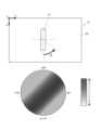
- the control unit 21 may also display on the display unit 23 a velocity map or the like that visualizes the position dependency and directional dependency of the horizontal propagation velocity in the object S, as shown in Figures 17A to 17C, based on the analysis results of the analysis unit 21f.
- FIG. 17A is an example of a two-dimensional map of the horizontal propagation velocity in the z direction
- FIG. 17B is an example of a two-dimensional map of the horizontal propagation velocity in the y direction
- FIG. 17C is an example of a two-dimensional map showing the directional dependency of the horizontal propagation velocity.
- the areas where the horizontal propagation velocity of the ultrasonic waves is relatively fast are shown in dark areas
- the areas where the horizontal propagation velocity of the ultrasonic waves is relatively slow are shown in light areas.
- the horizontal propagation velocity is faster in the 135° direction, so the elastic strength is increased in that direction.
- Such information is known to be closely related to the orientation state of the contained filler in fiber-reinforced resins such as CFRTP, and provides useful information when considering filler blending and shaping methods.
- Figures 17A to 17C show examples of velocity maps that display the degree of orientation in the object S in two dimensions, but in cases where the object S does not have an acoustic anisotropy axis on the first surface S1, a three-dimensional velocity map may be displayed.
- FIGs. 2, 4B, 10A and 10B an array-type sensor in which sensor elements 11 including transmitters 11a and receivers 11b are arranged in a one-dimensional array is shown as an example, but the present invention is not limited to this.
- it may be a matrix-type sensor in which multiple sensor elements 11 are arranged in a two-dimensional array (matrix).
- ultrasonic waves can be transmitted and received by disposing the transmitter 11a and receiver 11b at any position and/or direction of the object S by electronically selecting the sensor elements, without physically moving the sensor elements using the drive unit 12.
- a ROM is used as a computer-readable medium for the program according to the present invention, but this is not limiting.
- non-volatile memory such as a flash memory and portable recording media such as a CD-ROM can be applied.
- a carrier wave can also be applied to the present invention as a medium for providing data for the program according to the present invention via a communication line.
- the present invention can be used in a wave propagation velocity measurement method, a wave propagation velocity measurement device, and a program that can more easily measure the propagation velocity of elastic waves in a specified direction in an object with acoustic anisotropy.
Landscapes
- Physics & Mathematics (AREA)
- General Physics & Mathematics (AREA)
- Biochemistry (AREA)
- Life Sciences & Earth Sciences (AREA)
- Chemical & Material Sciences (AREA)
- Analytical Chemistry (AREA)
- Health & Medical Sciences (AREA)
- General Health & Medical Sciences (AREA)
- Immunology (AREA)
- Pathology (AREA)
- Acoustics & Sound (AREA)
- Engineering & Computer Science (AREA)
- Signal Processing (AREA)
- Investigating Or Analyzing Materials By The Use Of Ultrasonic Waves (AREA)
Priority Applications (1)
| Application Number | Priority Date | Filing Date | Title |
|---|---|---|---|
| JP2025537772A JPWO2025028145A1 (https=) | 2023-08-02 | 2024-07-04 |
Applications Claiming Priority (2)
| Application Number | Priority Date | Filing Date | Title |
|---|---|---|---|
| JP2023125979 | 2023-08-02 | ||
| JP2023-125979 | 2023-08-02 |
Publications (1)
| Publication Number | Publication Date |
|---|---|
| WO2025028145A1 true WO2025028145A1 (ja) | 2025-02-06 |
Family
ID=94394425
Family Applications (1)
| Application Number | Title | Priority Date | Filing Date |
|---|---|---|---|
| PCT/JP2024/024159 Pending WO2025028145A1 (ja) | 2023-08-02 | 2024-07-04 | 波動伝播速度計測方法、波動伝播速度計測装置及びプログラム |
Country Status (2)
| Country | Link |
|---|---|
| JP (1) | JPWO2025028145A1 (https=) |
| WO (1) | WO2025028145A1 (https=) |
Citations (9)
| Publication number | Priority date | Publication date | Assignee | Title |
|---|---|---|---|---|
| JPS61203359U (https=) * | 1985-06-12 | 1986-12-20 | ||
| JPS62207441A (ja) * | 1986-03-06 | 1987-09-11 | 株式会社東芝 | 超音波診断装置 |
| JPH02296147A (ja) * | 1989-05-10 | 1990-12-06 | Nkk Corp | 音響異方性測定方法および装置 |
| US5408882A (en) * | 1991-06-24 | 1995-04-25 | General Electric Company | Ultrasonic device and method for non-destructive evaluation of polymer composites |
| JPH07174736A (ja) * | 1993-12-17 | 1995-07-14 | Nippon Steel Corp | 斜角電磁超音波探傷装置の超音波伝播角度補正方法 |
| JP2000055891A (ja) * | 1998-08-12 | 2000-02-25 | Nkk Corp | 鋼管の超音波探傷方法及び鋼管の超音波探傷装置 |
| JP2007127547A (ja) | 2005-11-04 | 2007-05-24 | Nippon Steel Corp | 弾性定数計測装置、弾性定数計測方法、プログラム及びコンピュータ読み取り可能な記憶媒体 |
| JP2008286622A (ja) | 2007-05-17 | 2008-11-27 | Ihi Aerospace Co Ltd | 超音波測定装置と超音波測定方法 |
| CN104483385A (zh) * | 2014-12-05 | 2015-04-01 | 中国航空工业集团公司北京航空材料研究院 | 一种各向异性材料纵波声速的测量方法 |
-
2024
- 2024-07-04 JP JP2025537772A patent/JPWO2025028145A1/ja active Pending
- 2024-07-04 WO PCT/JP2024/024159 patent/WO2025028145A1/ja active Pending
Patent Citations (9)
| Publication number | Priority date | Publication date | Assignee | Title |
|---|---|---|---|---|
| JPS61203359U (https=) * | 1985-06-12 | 1986-12-20 | ||
| JPS62207441A (ja) * | 1986-03-06 | 1987-09-11 | 株式会社東芝 | 超音波診断装置 |
| JPH02296147A (ja) * | 1989-05-10 | 1990-12-06 | Nkk Corp | 音響異方性測定方法および装置 |
| US5408882A (en) * | 1991-06-24 | 1995-04-25 | General Electric Company | Ultrasonic device and method for non-destructive evaluation of polymer composites |
| JPH07174736A (ja) * | 1993-12-17 | 1995-07-14 | Nippon Steel Corp | 斜角電磁超音波探傷装置の超音波伝播角度補正方法 |
| JP2000055891A (ja) * | 1998-08-12 | 2000-02-25 | Nkk Corp | 鋼管の超音波探傷方法及び鋼管の超音波探傷装置 |
| JP2007127547A (ja) | 2005-11-04 | 2007-05-24 | Nippon Steel Corp | 弾性定数計測装置、弾性定数計測方法、プログラム及びコンピュータ読み取り可能な記憶媒体 |
| JP2008286622A (ja) | 2007-05-17 | 2008-11-27 | Ihi Aerospace Co Ltd | 超音波測定装置と超音波測定方法 |
| CN104483385A (zh) * | 2014-12-05 | 2015-04-01 | 中国航空工业集团公司北京航空材料研究院 | 一种各向异性材料纵波声速的测量方法 |
Also Published As
| Publication number | Publication date |
|---|---|
| JPWO2025028145A1 (https=) | 2025-02-06 |
Similar Documents
| Publication | Publication Date | Title |
|---|---|---|
| Bernard et al. | Resonant ultrasound spectroscopy for viscoelastic characterization of anisotropic attenuative solid materials | |
| Makoond et al. | Dynamic elastic properties of brick masonry constituents | |
| Webersen et al. | Guided ultrasonic waves for determining effective orthotropic material parameters of continuous-fiber reinforced thermoplastic plates | |
| Coppieters et al. | On the synergy between physical and virtual sheet metal testing: calibration of anisotropic yield functions using a microstructure-based plasticity model | |
| D'Emilia et al. | Calibration of tri-axial MEMS accelerometers in the low-frequency range–Part 1: comparison among methods | |
| Yonezu et al. | A method to estimate residual stress in austenitic stainless steel using a microindentation test | |
| Prates et al. | Identification of material parameters for thin sheets from single biaxial tensile test using a sequential inverse identification strategy | |
| Yamamoto et al. | Determination of elastic constants in complex-shaped materials through vibration-mode-pattern-matching-assisted resonant ultrasound spectroscopy | |
| Li et al. | Non-destructive mapping of stress and strain in soft thin films through sound waves | |
| Jakes et al. | Contact area correction for surface tilt in pyramidal nanoindentation | |
| WO2025028145A1 (ja) | 波動伝播速度計測方法、波動伝播速度計測装置及びプログラム | |
| Johannesmann et al. | An acoustic waveguide-based approach to the complete characterisation of linear elastic, orthotropic material behaviour | |
| Bause et al. | Transient modeling of ultrasonic guided waves in circular viscoelastic waveguides for inverse material characterization | |
| Kovář et al. | The discrepancy between the indentation curves obtained by the finite element method calculation with a Berkovich and a conical indenter | |
| Mandal et al. | Experimental investigation of vibration power flow in thin technical orthotropic plates by the method of vibration intensity | |
| Fisher et al. | Modeling and characterizing the elastodynamic response of octet-truss lattice structures using resonance techniques | |
| JP3953754B2 (ja) | 密度不均一試料解析方法ならびにその装置およびシステム | |
| JP5447323B2 (ja) | 音速分布測定装置、音速分布測定方法及びプログラム | |
| Henning et al. | Computer-assisted design of transducers for ultrasonic sensor systems | |
| Claus et al. | Dynamic experiments using simultaneous compression and shear loading | |
| JP2779201B2 (ja) | 構造物の力学的異方性測定法 | |
| CA2669865A1 (en) | Method and system for determining young's modulus and poisson's ratio for a crystalline material | |
| Shigematsu et al. | Friction drive of an SAW motor. Part II: Analyses | |
| Park et al. | Measurement of viscoelastic properties from the vibration of a compliantly supported beam | |
| Johannesmann et al. | Characterization of the linear-acoustic material behavior of fiber-reinforced composites using lamb waves |
Legal Events
| Date | Code | Title | Description |
|---|---|---|---|
| 121 | Ep: the epo has been informed by wipo that ep was designated in this application |
Ref document number: 24848804 Country of ref document: EP Kind code of ref document: A1 |
|
| ENP | Entry into the national phase |
Ref document number: 2025537772 Country of ref document: JP Kind code of ref document: A |
|
| WWE | Wipo information: entry into national phase |
Ref document number: 2025537772 Country of ref document: JP |
|
| WWE | Wipo information: entry into national phase |
Ref document number: 2024848804 Country of ref document: EP |
|
| NENP | Non-entry into the national phase |
Ref country code: DE |