WO2025028024A1 - X線撮影システム - Google Patents
X線撮影システム Download PDFInfo
- Publication number
- WO2025028024A1 WO2025028024A1 PCT/JP2024/020729 JP2024020729W WO2025028024A1 WO 2025028024 A1 WO2025028024 A1 WO 2025028024A1 JP 2024020729 W JP2024020729 W JP 2024020729W WO 2025028024 A1 WO2025028024 A1 WO 2025028024A1
- Authority
- WO
- WIPO (PCT)
- Prior art keywords
- arm
- angle
- dose
- ray
- unit
- Prior art date
- Legal status (The legal status is an assumption and is not a legal conclusion. Google has not performed a legal analysis and makes no representation as to the accuracy of the status listed.)
- Pending
Links
Images









Classifications
-
- A—HUMAN NECESSITIES
- A61—MEDICAL OR VETERINARY SCIENCE; HYGIENE
- A61B—DIAGNOSIS; SURGERY; IDENTIFICATION
- A61B6/00—Apparatus or devices for radiation diagnosis; Apparatus or devices for radiation diagnosis combined with radiation therapy equipment
-
- A—HUMAN NECESSITIES
- A61—MEDICAL OR VETERINARY SCIENCE; HYGIENE
- A61B—DIAGNOSIS; SURGERY; IDENTIFICATION
- A61B6/00—Apparatus or devices for radiation diagnosis; Apparatus or devices for radiation diagnosis combined with radiation therapy equipment
- A61B6/10—Safety means specially adapted therefor
Definitions
- the present invention relates to an X-ray imaging system that displays the distribution of X-ray dose.
- U.S. Patent Application Publication No. 2011/0317815 describes an X-ray imaging device that displays the distribution of X-ray doses irradiated onto the surface of a patient.
- the X-ray imaging device described in U.S. Patent Application Publication No. 2011/0317815 includes an arm that supports, in opposing relation to each other, an X-ray irradiation unit having an X-ray source that irradiates X-rays, and an X-ray detection unit that detects the X-rays irradiated from the X-ray irradiation unit.
- X-ray imaging devices such as those described in U.S. Patent Application Publication No. 2011/0317815 are used in interventional radiology (IVR).
- IVR interventional radiology
- conventional X-ray imaging devices such as those described in U.S. Patent Application Publication No. 2011/0317815 may have two arms that support an X-ray irradiation unit and an X-ray detection unit facing each other.
- This invention has been made to solve the problems described above, and one objective of the invention is to provide an X-ray imaging system with two arms that can prevent an operator from setting the target angles of the arms in a way that causes interference between the two arms while viewing the distribution of X-ray dose.
- the X-ray imaging system includes a first arm that supports, in opposing relation, a first X-ray irradiator having an X-ray source that irradiates X-rays and a first X-ray detection unit that detects the X-rays irradiated from the first X-ray irradiator, a second arm that supports, in opposing relation, a second X-ray irradiator having an X-ray source and a second X-ray detection unit that detects the X-rays irradiated from the second X-ray irradiator, and a second arm that displays an angle of the first arm and an angle of the second arm, a first dose distribution that is the dose of X-rays irradiated by the first X-ray irradiator, a second dose distribution that is the dose of X-rays irradiated by the second X-ray irradiator, and a second range
- the device includes a display unit that displays an irradiation range screen including the first irradiation range and a second irradiation range that is an irradiation range of X-rays by the second X-ray irradiation unit, an operation unit that accepts an operation to set a target angle of the first arm and a target angle of the second arm on the dose distribution screen displayed on the display unit, and a movement mechanism that moves the first arm and the second arm based on the target angle of the first arm and the target angle of the second arm set by the operation unit, and the display unit is configured to display a range in which the first arm and the second arm do not interfere with each other on the dose distribution screen when at least one of the target angle of the first arm and the target angle of the second arm is set by the operation unit.
- the display unit is configured to display on the dose distribution screen the range in which the first arm and the second arm do not interfere with each other when setting at least one of the target angles of the first arm and the second arm with the operation unit.
- This allows the operator to visually recognize the range in which the first arm and the second arm do not interfere with each other when setting at least one of the target angles of the first arm and the second arm with the operation unit on the dose distribution screen.
- This makes it possible, in a configuration with two arms, to prevent the operator from setting the target angles of the arms in a way that causes the two arms to interfere with each other while viewing the distribution of X-ray dose.
- FIG. 1 is a schematic diagram for explaining the configuration of an X-ray imaging system according to an embodiment of the present invention.
- 1 is a block diagram showing the overall configuration of an X-ray imaging system according to an embodiment of the present invention.
- FIG. 4 is a diagram for explaining a display on a monitor according to the present embodiment.
- 2 is a block diagram for explaining the functional configuration of a dose calculation processing unit according to the present embodiment.
- FIG. 11 is a diagram for explaining acquisition of the positional relationship between the tabletop and the first and second imaging units;
- FIG. 11 is a diagram for explaining calculation of X-ray dose distribution in a virtual model.
- FIG. 11 is a diagram for explaining correspondence between the surface of the virtual model and the angle of the imaging unit.
- FIG. 13 is a diagram for explaining an angular dose image and a color scale image.
- 13 is a diagram for explaining updating of an angular dose image when the tabletop is moved in the up-down direction of the subject;
- FIG. 13 is a diagram for explaining updating of an angular dose image when the tabletop is moved in the left-right direction of the subject;
- FIG. 13 is a diagram for explaining updating of an angular dose image when the tabletop is moved in the vertical direction.
- FIG. 13A and 13B are diagrams for explaining updating of an angular dose image when an angular interval is changed.
- 11A and 11B are diagrams for explaining setting of a target angle of a first arm.
- 11 is a diagram for explaining setting of a target angle of a second arm.
- FIG. 13 is a diagram for explaining a warning display indicating that the set target angle is within a range in which the first arm and the second arm interfere with each other.
- FIG. 13 is a diagram for explaining a warning display indicating that the set target angle is in a range in which the first dose and the second dose exceed predetermined threshold values.
- FIG. 13 is a diagram showing an example of a display of a recommended angle region.
- FIG. 13 is a diagram showing an example of a timeline display.
- 13 is a diagram showing an example of a display for selecting an imaging unit angle on a touch panel.
- FIG. FIG. 13 is a diagram showing a display of an angle dose image on a touch panel.
- FIG. 13 is a diagram showing an example of a three-dimensional image display.
- the X-ray imaging system 100 is a device that takes an X-ray image 41 (see FIG. 3) of the inside of a subject P, such as a human body, by irradiating the subject P with X-rays from the outside.
- An operator using the X-ray imaging system 100 can perform various treatments such as interventional radiology (IVR) by inserting a medical device such as a catheter into the blood vessels of the subject P (for example, the blood vessels of the subject P's heart) while viewing the X-ray image 41 of the subject P.
- IVR interventional radiology
- the term "operator using the X-ray imaging system 100" is not limited to the surgeon (doctor) who treats the subject P, but also includes an operator who simply operates the X-ray imaging system 100 without being directly involved in the treatment of the subject P.
- the X-ray imaging system 100 includes a tabletop 1, a first imaging unit 2A, a second imaging unit 2B, a moving mechanism 3, a monitor 4, a touch panel 5, and an operation unit 6.
- the monitor 4 is an example of a "display unit” in the claims.
- the touch panel 5 is an example of a “display unit” and an “operation unit” in the claims.
- the tabletop 1 is configured as an examination table on which the subject P lies (is placed) when X-ray imaging is performed.
- the tabletop 1 is supported by a tabletop support part 11.
- the first imaging unit 2A captures an X-ray image 41 (see Fig. 3) of the subject P.
- the first imaging unit 2A also includes a first X-ray irradiator 21A and a first X-ray detector 22A.
- the first X-ray irradiator 21A and the first X-ray detector 22A are supported by a first arm 23A so as to face each other across the tabletop 1 on which the subject P lies.
- the X-ray imaging system 100 includes a first arm 23A that supports the first X-ray irradiator 21A and the first X-ray detector 22A so as to face each other.
- the first X-ray irradiator 21A has an X-ray source 21Aa and a collimator 21Ab.
- the X-ray source 21Aa irradiates X-rays to the subject P lying on the tabletop 1.
- the X-ray source 21Aa is connected to a high voltage generator (not shown) and is an X-ray tube that generates X-rays by applying a high voltage and irradiates the subject P with the generated X-rays.
- the X-ray source 21Aa is arranged with the X-ray emission direction facing the detection surface of the first X-ray detector 22A.
- the collimator 21Ab is configured to adjust the irradiation field of the X-rays irradiated by the X-ray source 21Aa.
- the first X-ray irradiator 21A generates X-rays according to preset imaging conditions such as tube voltage, tube current, and time interval of X-ray irradiation under the control of the control device 101 described later.
- the first X-ray detection unit 22A detects the X-rays irradiated from the first X-ray irradiation unit 21A. The first X-ray detection unit 22A then outputs a detection signal according to the detected X-ray intensity.
- the first X-ray detection unit 22A is configured, for example, by an FPD (Flat Panel Detector).
- the first X-ray detection unit 22A is connected to the control device 101, which will be described later.
- the second imaging unit 2B takes an X-ray image 41 (see FIG. 3) of the subject P.
- the second imaging unit 2B also includes a second X-ray irradiator 21B and a second X-ray detector 22B.
- the second X-ray irradiator 21B and the second X-ray detector 22B are supported by a second arm 23B so as to face each other across the tabletop 1 on which the subject P lies.
- the X-ray imaging system 100 includes a second arm 23B that supports the second X-ray irradiator 21B and the second X-ray detector 22B so as to face each other.
- the second X-ray irradiator 21B has an X-ray source 21Ba and a collimator 21Bb.
- the X-ray source 21Ba irradiates X-rays to the subject P lying on the tabletop 1.
- the X-ray source 21Ba is connected to a high voltage generator (not shown) and is an X-ray tube that generates X-rays by applying a high voltage and irradiates the subject P with the generated X-rays.
- the X-ray source 21Ba is arranged with the X-ray emission direction facing the detection surface of the second X-ray detector 22B.
- the collimator 21Bb is configured to adjust the irradiation field of the X-rays irradiated by the X-ray source 21Ba.
- the second X-ray irradiator 21B generates X-rays according to preset imaging conditions such as tube voltage, tube current, and time interval of X-ray irradiation under the control of the control device 101 described later.
- the second X-ray detection unit 22B detects the X-rays irradiated from the second X-ray irradiation unit 21B. The second X-ray detection unit 22B then outputs a detection signal according to the detected X-ray intensity.
- the second X-ray detection unit 22B is configured, for example, by an FPD (Flat Panel Detector).
- the second X-ray detection unit 22B is connected to the control device 101, which will be described later.
- the moving mechanism 3 moves at least one of the tabletop 1, the first imaging unit 2A, and the second imaging unit 2B. Specifically, the moving mechanism 3 changes the relative positional relationship between the tabletop 1 and the first imaging unit 2A, thereby changing the position of the body surface of the subject P to which X-rays are irradiated by the first X-ray irradiator 21A. The moving mechanism 3 also changes the relative positional relationship between the tabletop 1 and the second imaging unit 2B, thereby changing the position of the body surface of the subject P to which X-rays are irradiated by the second X-ray irradiator 21B.
- the movement mechanism 3 includes a tabletop movement mechanism 31 that moves the tabletop 1, a first image pickup unit movement mechanism 32A that changes the angle of the first image pickup unit 2A (angle of the first arm 23A), and a second image pickup unit movement mechanism 32B that changes the angle of the second image pickup unit 2B (angle of the second arm 23B).
- the tabletop movement mechanism 31 is configured to be able to move the tabletop 1 in the horizontal direction (direction parallel to the horizontal plane) and the vertical direction.
- the tabletop movement mechanism 31 is also configured to be able to change the angle of the tabletop 1.
- the first image pickup unit movement mechanism 32A is configured to be able to change the position and angle of the first image pickup unit 2A (first arm 23A).
- the first image pickup unit movement mechanism 32A is also configured to be able to change the distance between the first X-ray irradiation unit 21A and the first X-ray detection unit 22A.
- the second image pickup unit movement mechanism 32B is configured to be able to change the position and angle of the second image pickup unit 2B (second arm 23B).
- the second imaging unit moving mechanism 32B is configured to be able to change the distance between the second X-ray irradiation unit 21B and the second X-ray detection unit 22B.
- the moving mechanism 3 includes, for example, a servo motor controlled by the control device 101 described below.
- a fluoroscopic image of the heart (X-ray image 41 (see FIG. 3)) is continuously acquired as a moving image, and the treatment is performed while changing the X-ray irradiation angle (angle of the first imaging unit 2A) by the first X-ray irradiator 21A and the X-ray irradiation angle (angle of the second imaging unit 2B) by the second X-ray irradiator 21B in order to suppress an increase in the local X-ray dose on the body surface (skin) of the subject P.
- IVR imaging-guided therapy
- the moving mechanism 3 is configured to change the angle of the first imaging unit 2A and the angle of the second imaging unit 2B by a control process by the control device 101, which will be described later.
- the angle of the first imaging unit 2A is the angle in the direction in which the first X-ray irradiator 21A and the first X-ray detector 22A face each other.
- the angle of the second imaging unit 2B is the angle in the direction in which the second X-ray irradiator 21B and the second X-ray detector 22B face each other.
- the angle of the first imaging unit 2A is changed so that the first X-ray detection unit 22A moves to the LAO (left anterior oblique) and RAO (right anterior oblique), which are the left and right directions of the subject P, and to the CRA (cranial) and CAU (caudal), which are the up and down directions (head side and leg side) of the subject P, based on the state in which the first X-ray irradiation unit 21A and the first X-ray detection unit 22A are arranged along the vertical direction.
- the angle of the second imaging unit 2B is changed so that the second X-ray detection unit 22B moves to the LAO and RAO, and to the CRA and CAU, based on the state in which the second X-ray irradiation unit 21B and the second X-ray detection unit 22B are arranged along the vertical direction.
- monitor 4 displays an X-ray image 41, an angular dose image 42, a color scale image 43, a maximum value display 44, a timeline display 45 (see FIG. 18), and a three-dimensional image 46 under the control of a control device 101, which will be described later.
- Monitor 4 includes a display monitor, which is a device that displays video signals of still images or videos output from a device such as a computer. Details of the display on monitor 4 will be described later.
- the angular dose image 42 is an example of a "dose distribution screen" in the claims.
- the touch panel 5 accepts input operations by an operator (surgeon or operator) to operate the X-ray imaging system 100.
- the touch panel 5 is configured to transmit an input signal based on the accepted input operation to the control device 101 and dose calculation device 102 described below.
- the touch panel 5 is a tablet PC having a calculation device such as a CPU (Central Processing Unit) and a storage unit such as a flash memory, and is configured to be able to communicate with the control device 101 and dose calculation device 102 described below.
- the touch panel 5 is configured to display a display related to the selection of the angle of the first imaging unit 2A and the angle of the second imaging unit 2B. The display of the touch panel 5 will be described in detail later.
- the operation unit 6 like the touch panel 5, accepts input operations by an operator (surgeon or operator).
- the operation unit 6 includes, for example, a pointing device such as a keyboard or a mouse.
- the operation unit 6 also includes an irradiation button that accepts an input operation to irradiate X-rays, and a movement operation button that accepts an input operation to move the tabletop 1 and the first and second imaging units 2A and 2B.
- the operation unit 6 is also configured to transmit an input signal based on the accepted input operation to the control device 101, which will be described later.
- each part of the X-ray imaging system 100 is controlled based on input operations on the touch panel 5 and the operation unit 6.
- the touch panel 5 and the operation unit 6 accept an input operation to select (change) the angle at which X-ray imaging is performed from among the angles of the multiple first imaging unit 2A. They also accept an input operation to select (change) the angle at which X-ray imaging is performed from among the angles of the multiple second imaging unit 2B.
- the touch panel 5 and the operation unit 6 also accept an input operation to change the display on the monitor 4.
- the touch panel 5 and the operation unit 6 also accept an input operation to irradiate X-rays.
- the X-ray imaging system 100 also includes a control device 101, a dose calculation device 102, and a three-dimensional image generation device 103.
- the control device 101 is a computer (computing device) including a CPU, a GPU (Graphics Processing Unit), a ROM (Read Only Memory), and a RAM (Random Access Memory).
- the control device 101 also includes storage devices such as a HDD (Hard Disk Drive) and an SSD (Solid State Drive).
- the control device 101 controls the operation of the X-ray imaging system 100 based on the operation by the operator.
- the control device 101 also controls the display of the monitor 4. That is, the control device 101 controls the X-ray imaging by controlling the first imaging unit 2A and the second imaging unit 2B, and generates the X-ray image 41.
- control device 101 controls the operation of the first X-ray irradiator 21A and the second X-ray irradiator 21B to irradiate X-rays to the subject P.
- the control device 101 also acquires detection signals output from the first X-ray detector 22A and the second X-ray detector 22B, and generates an X-ray image 41 based on the acquired detection signals.
- the X-ray image 41 is an image showing the inside of the subject P based on the detection signal of the X-rays that have passed through the subject P.
- the X-ray image 41 is continuously acquired so that the operator can observe the state inside the subject P in real time.
- the X-ray image 41 is configured to be displayed on the monitor 4 as a moving image.
- the control device 101 also changes the relative position and angle between the tabletop 1 and the first and second imaging units 2A and 2B, and between the tabletop 1 and the second imaging unit 2B, by controlling the operation of the movement mechanism 3 based on input operations on the touch panel 5 and the operation unit 6.
- the control device 101 is configured to set the angle at which X-ray imaging is to be performed by the first and second imaging units 2A and 2B, by controlling the operation of the movement mechanism 3.
- the dose calculation device 102 has a dose calculation processing unit 70, which is a computer (arithmetic device) including a CPU, GPU, ROM, and RAM.
- the dose calculation device 102 also has a storage device such as an HDD or SSD that stores a predetermined program for operating the dose calculation processing unit 70.
- the storage device also stores a virtual model Pa, which will be described later, and various setting values (parameters).
- the storage device also stores a history of the dose of X-rays irradiated to the subject P.
- the dose calculation processing unit 70 is configured to calculate the dose of X-rays irradiated to the subject P.
- the three-dimensional image generating device 103 is a computer (arithmetic device) including a CPU, a GPU, a ROM, and a RAM, similar to the control device 101 and the dose calculation device 102.
- the three-dimensional image generating device 103 generates a three-dimensional image 46. The generation of the three-dimensional image 46 will be described in detail later.
- control device 101 In the X-ray imaging system 100, the control device 101, the dose calculation device 102, and the three-dimensional image generation device 103 are configured to transmit and receive signals to each other.
- the control device 101, the dose calculation device 102, and the three-dimensional image generation device 103 are connected to each other via a computer network such as a LAN (Local Area Network).
- LAN Local Area Network
- the monitor 4 displays the X-ray dose calculated by the dose calculation device 102. Specifically, the monitor 4 is configured to display an angle dose image 42 generated by the dose calculation device 102. Specifically, the angle dose image 42 generated by the dose calculation device 102 is transmitted to the control device 101. Then, the control device 101 causes the monitor 4 to display the angle dose image 42.
- the dose calculation processing unit 70 of the dose calculation device 102 includes, as functional components, a positional relationship acquisition unit 71, a model dose calculation unit 72, an angle matching unit 73, an angle dose calculation unit 74, an image generation unit 75, an irradiation area calculation unit 76, a storage processing unit 77, and a dose prediction unit 78. That is, the dose calculation processing unit 70 functions as the positional relationship acquisition unit 71, the model dose calculation unit 72, the angle matching unit 73, the angle dose calculation unit 74, the image generation unit 75, the irradiation area calculation unit 76, the storage processing unit 77, and the dose prediction unit 78 by executing a predetermined program stored in the storage device.
- the positional relationship acquisition unit 71 (dose calculation processing unit 70) is configured to acquire the virtual positional relationship between the virtual model Pa and the first and second imaging units 2A and 2B based on the positional relationship between the tabletop 1 and the first and second imaging units 2A and 2B. Note that the second imaging unit 2B is not shown in FIG. 5.
- the dose calculation device 102 is configured to acquire the position and angle of the tabletop 1, the position and angle of the first imaging unit 2A, and the position and angle of the second imaging unit 2B from the control device 101.
- the positional relationship acquisition unit 71 acquires the positional relationship between the tabletop 1, the first imaging unit 2A, and the second imaging unit 2B in the three-dimensional virtual space based on the acquired position and angle of the tabletop 1, the position and angle of the first imaging unit 2A (the first X-ray irradiation unit 21A and the first X-ray detection unit 22A), and the position and angle of the second imaging unit 2B (the second X-ray irradiation unit 21B and the second X-ray detection unit 22B).
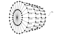
- the positional relationship acquisition unit 71 also acquires a virtual model Pa (see FIG. 6) representing the subject P lying on the tabletop 1 in the three-dimensional virtual space.
- the virtual model Pa is a three-dimensional model having a cylindrical shape.
- the virtual model Pa is also stored in advance in the storage device of the dose calculation device 102.
- the size of the virtual model Pa may be changed according to the body size (BMI: Body Mass Index, etc.) of the subject P.
- the positional relationship acquisition unit 71 acquires the virtual positional relationship between the first imaging unit 2A and the second imaging unit 2B and the virtual model Pa in the three-dimensional virtual space.
- the position of the virtual model Pa in the three-dimensional virtual space is set based on the position and angle of the tabletop 1.
- the model dose calculation unit 72 (dose calculation processing unit 70) is configured to calculate the distribution of X-ray doses on the surface of the three-dimensional virtual model Pa based on the dose of X-rays irradiated to the subject P by X-ray irradiation from the first imaging unit 2A (first X-ray irradiator 21A) and the dose of X-rays irradiated to the subject P by X-ray irradiation from the second imaging unit 2B (second X-ray irradiator 21B). Note that the second imaging unit 2B is not shown in FIG. 6.
- the dose calculation device 102 acquires from the control device 101 the period during which X-rays were irradiated, the imaging unit angles (the angle of the first imaging unit 2A and the angle of the second imaging unit 2B), and imaging conditions such as tube voltage, tube current, and time interval of X-ray irradiation.
- the dose calculation device 102 also acquires from the control device 101 the dose of X-rays irradiated to the subject P and the imaging unit angle in association with each other.
- the model dose calculation unit 72 then calculates the integrated value of the X-ray dose on the surface of the virtual model Pa based on the dose of X-rays irradiated to the subject P, the imaging unit angle, and the virtual positional relationship between the first imaging unit 2A and the second imaging unit 2B and the virtual model Pa in the three-dimensional virtual space.
- the model dose calculation unit 72 then updates the integrated value of the X-ray dose on the surface of the virtual model Pa every time X-rays are irradiated by the first imaging unit 2A and the second imaging unit 2B.
- the model dose calculation unit 72 calculates the integrated value of the X-ray dose for each microelement on the surface of the virtual model Pa, which is divided into microelements.
- the angle matching unit 73 (dose calculation processing unit 70) is configured to match the imaging unit angle to the surface of the virtual model Pa based on the imaging unit angle (the angle of the first imaging unit 2A and the angle of the second imaging unit 2B) and the position on the surface of the virtual model Pa where the X-rays are irradiated.
- the angle matching unit 73 acquires positions on the surface of the virtual model Pa where X-rays are irradiated for each imaging unit angle (angle of the first imaging unit 2A and angle of the second imaging unit 2B) at a predetermined angle interval, based on the virtual positional relationship between the first imaging unit 2A and the second imaging unit 2B and the virtual model Pa in the three-dimensional virtual space. For example, when the predetermined angle interval is 10 degrees, the angle matching unit 73 acquires the imaging unit angle when the imaging unit angle is vertical (reference direction) as (0,0), the imaging unit angle when tilted 10 degrees to the LAO as (10,0), and the imaging unit angle when tilted 20 degrees to the LAO as (20,0).
- the angle matching unit 73 also acquires the imaging unit angle when tilted 10 degrees to the LAO and 10 degrees to the CRA as (10,10).
- the angle matching unit 73 maps the positions of the centers (centers of the field of view) of the irradiation axes of the X-rays irradiated from the first imaging unit 2A and the second imaging unit 2B to the surface of the virtual model Pa at predetermined angular intervals (for example, 10 degrees) based on the positional relationship between the first imaging unit 2A and the second imaging unit 2B and the virtual model Pa at predetermined angular intervals in the three-dimensional virtual space so as to correspond to the positions on the surface of the virtual model Pa.
- the angle dose calculation unit 74 (dose calculation processing unit 70) is configured to calculate the X-ray dose in each of a plurality of angle regions partitioned at a predetermined angle interval of the imaging unit angle based on the distribution of X-ray dose on the surface of the virtual model Pa calculated by the model dose calculation unit 72 and the imaging unit angles (the angle of the first imaging unit 2A and the angle of the second imaging unit 2B) associated with the surface of the virtual model Pa by the angle association unit 73.
- the image generation unit 75 (dose calculation processing unit 70) then generates an angle dose image 42 in which the magnitude of the X-ray dose in each of the plurality of angle regions calculated by the angle dose calculation unit 74 can be distinguished.
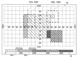
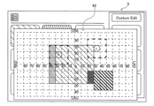
- the angle dose image 42 is an image in which a plurality of angle regions are partitioned in a lattice pattern at a predetermined angle interval of the imaging unit angle, and the magnitude of the X-ray dose in each of the plurality of angle regions partitioned in a lattice pattern can be distinguished.
- the angular dose image 42 is an image including the angles of the first arm 23A and the second arm 23B, and a distribution of the first dose, which is the dose of X-rays irradiated by the first X-ray irradiator 21A, and a distribution of the second dose, which is the dose of X-rays irradiated by the second X-ray irradiator 21B, which are associated with the angles of the first arm 23A and the second arm 23B.
- the angular dose image 42 generated by the image generator 75 is output from the dose calculator 102 to the control device 101 and displayed on the monitor 4.
- the angular dose calculation unit 74 obtains the maximum X-ray dose in each of the angular regions (see FIG. 7) partitioned at predetermined angular intervals on the surface of the virtual model Pa by the angle matching unit 73 based on the distribution of X-ray dose on the surface of the virtual model Pa. Then, the image generation unit 75 generates an angular dose image 42 in which the directions of LAO and RAO are set as the horizontal axis and the directions of CRA and CAU are set as the vertical axis, with each angular region being partitioned into a square at predetermined angular intervals (for example, 10 degrees).
- the size of the angular interval on the horizontal axis and the size of the angular interval on the vertical axis are configured to be approximately the same size (scale). Furthermore, the ranges of the vertical and horizontal axes are set based on the movable angular ranges of the first imaging unit 2A and the second imaging unit 2B.
- the magnitude of the X-ray dose in each of the multiple angle regions is represented by color coding.
- the magnitude of the X-ray dose is represented by five colors, purple, red, orange, yellow, and green, in order of decreasing dose. Note that in Figure 8, differences in color coding are represented by differences in hatching.
- the image generating unit 75 generates a color scale image 43 that indicates the standard for color-coding the angle dose image 42.
- the areas are displayed in the order of increasing X-ray dose, purple, red, orange, yellow, and green, in order of decreasing X-ray dose, so as to correspond to the color-coding of the angle dose image 42.
- numerical values indicating the specific X-ray dose values that serve as the standard for color-coding are displayed.
- areas where the maximum X-ray dose is greater than 4000 mGy are displayed as purple, areas where the maximum dose is greater than 3000 mGy and less than or equal to 4000 mGy are displayed as red, areas where the maximum X-ray dose is greater than 2000 mGy and less than or equal to 3000 mGy are displayed as orange, areas where the maximum X-ray dose is greater than 1000 mGy and less than or equal to 2000 mGy are displayed as yellow, and areas where the maximum X-ray dose is greater than 0 mGy and less than or equal to 1000 mGy are displayed as green.
- a display showing preset X-ray dose thresholds 43a and 43b is displayed so as to be superimposed on the color scale image 43.
- the thresholds 43a and 43b are preset by the operator.
- a warning message is displayed on the monitor 4.
- the warning message is displayed, for example, as text (text information) in a predetermined portion of the monitor 4. Then, the display of the warning message on the monitor 4 is stopped after a predetermined time has elapsed or due to an input operation on the operation unit 6, etc.
- the monitor 4 may also display the total skin dose of the subject P during surgery.
- the dose calculation processing unit 70 calculates the total X-ray dose on the entire body surface of the subject P based on the acquired X-ray dose.
- the calculated total X-ray dose is then output from the dose calculation device 102 to the control device 101, and is displayed on the monitor 4 by control processing by the control device 101.
- the angle correlator 73 is configured to update the correspondence of the imaging unit angles (the angle of the first imaging unit 2A and the angle of the second imaging unit 2B) on the surface of the virtual model Pa based on the virtual positional relationship acquired by the positional relationship acquisition unit 71 when the positional relationship between the tabletop 1 and the first and second imaging units 2A and 2B is changed.
- the angular dose calculator 74 is configured to update the X-ray dose in each of the multiple angular regions based on the updated correspondence of the imaging unit angles on the surface of the virtual model Pa.
- the image generator 75 is configured to regenerate the angular dose image 42 based on the updated X-ray dose in each of the multiple angular regions.
- the positional relationship acquisition unit 71 updates the position and angle of the virtual model Pa in the three-dimensional virtual space based on information indicating the position and angle of the tabletop 1 newly acquired from the control device 101. Also, when an operation to change the position and angle of the first imaging unit 2A is accepted, the positional relationship acquisition unit 71 updates the position and angle of the first imaging unit 2A in the three-dimensional virtual space based on information indicating the position and angle of the first imaging unit 2A newly acquired from the control device 101.
- the angle correspondence unit 73 updates the correspondence (mapping) of the imaging unit angles on the surface of the virtual model Pa by newly acquiring (calculating) the positions at which X-rays are irradiated for each imaging unit angle (the angle of the first imaging unit 2A and the angle of the second imaging unit 2B) at predetermined angle intervals on the surface of the virtual model Pa based on the changed virtual positional relationship. Then, the angle correspondence unit 73 reacquires the newly partitioned angular area on the surface of the virtual model Pa based on the updated correspondence (mapping).
- the angle dose calculation unit 74 recalculates the X-ray dose in each of the multiple angle regions divided at a predetermined angle interval based on the distribution of X-ray dose on the surface of the virtual model Pa calculated by the model dose calculation unit 72 and the angle region by the correspondence of the imaging unit angles (the angle of the first imaging unit 2A and the angle of the second imaging unit 2B) updated by the angle correspondence unit 73. Then, the image generation unit 75 updates the angle dose image 42 so that the magnitude of the X-ray dose in each of the newly recalculated multiple angle regions can be distinguished.
- the degree of distribution of the X-ray dose in the angle dose image 42 changes based on the X-ray dose in each of the newly recalculated multiple angle regions. Note that when only the imaging unit angle is moved (changed) without moving the tabletop 1, the correspondence of the imaging unit angle on the surface of the virtual model Pa in the three-dimensional virtual space is not changed. In other words, when only the imaging unit angle is changed, the angular dose image 42 is not updated, and the degree of distribution of the X-ray dose in the angular dose image 42 does not change.
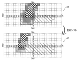
- the degree of distribution of the X-ray dose in the angular dose image 42 shifts in the vertical direction (the CRA and CAU directions).
- the degree of distribution of the X-ray dose in the angle dose image 42 also changes.
- the degree of distribution of the X-ray dose in the angle dose image 42 also changes. Note that the change in the degree of distribution of the X-ray dose in the angle dose image 42 when the positional relationship between the tabletop 1 and the first imaging unit 2A and the second imaging unit 2B is changed is different from simple parallel (shift) movement and zooming, because the correspondence of the imaging unit angles (the angle of the first imaging unit 2A and the angle of the second imaging unit 2B) on the surface of the cylindrical virtual model Pa is changed.
- the angular dose calculator 74 (dose calculation processor 70) is configured to calculate an X-ray dose in each of the angular regions divided by the predetermined angular intervals whose size has been changed when an operation to change the size of the predetermined angular intervals dividing the angular regions is received by the touch panel 5 or the operation unit 6.
- the image generator 75 then generates an angular dose image 42 in which the magnitude of the X-ray dose in each of the angular regions whose size of the predetermined angular interval has been changed can be distinguished.
- the monitor 4 is then configured to display the angular dose image 42 in which the size of the predetermined angular interval has been changed.
- the angle matching unit 73 updates the correspondence (mapping) of the imaging unit angles (the angle of the first imaging unit 2A and the angle of the second imaging unit 2B) on the surface of the virtual model Pa so that the predetermined angle intervals whose sizes have been changed are partitioned, thereby reacquiring the newly partitioned angle areas on the surface of the virtual model Pa.
- the angle dose calculation unit 74 recalculates the X-ray dose in each of the angle areas whose sizes have been updated.
- the image generation unit 75 updates the angle dose image 42 so that the magnitude of the X-ray dose in each of the newly recalculated multiple angle areas can be distinguished.
- the image generation unit 75 generates the angle dose image 42 in which the size of each partitioned angle area has been changed in accordance with the change in the angle interval. For example, when the predetermined angle interval is changed from 10 degrees to 5 degrees, the size of the angle dose image 42 itself is not changed, and the size of the partitions in the angle dose image 42 is halved.
- the X-ray dose is displayed in a distinguishable color based on the distribution of X-ray dose in the angular regions divided every 5 degrees on the surface of the virtual model Pa.
- the angular dose image 42 is an image including a first irradiation area indication 42Aa which is an irradiation area of X-rays by the first X-ray irradiator 21A and a second irradiation area indication 42Ba which is an irradiation area of X-rays by the second X-ray irradiator 21B.
- the first irradiation area indication 42Aa and the second irradiation area indication 42Ba are examples of the "first irradiation area” and the "second irradiation area” in the claims, respectively.
- the irradiation area calculation unit 76 (dose calculation processing unit 70) is configured to calculate the irradiation area of the first X-ray irradiation unit 21A and the irradiation area of the second X-ray irradiation unit 21B, which are areas on the surface of the virtual model Pa to which X-rays are irradiated at the current imaging unit angle (the angle of the first imaging unit 2A and the angle of the second imaging unit 2B).
- the irradiation area calculation unit 76 calculates the irradiation area (the irradiation area of the first X-ray irradiation unit 21A and the irradiation area of the second X-ray irradiation unit 21B) on the surface of the virtual model Pa to which X-rays are irradiated at the current imaging unit angle based on the virtual positional relationship between the virtual model Pa and the first imaging unit 2A and the second imaging unit 2B in the three-dimensional virtual space acquired by the positional relationship acquisition unit 71 and the shooting conditions acquired from the control device 101.
- the irradiation area calculation unit 76 acquires, as an angle area included in the irradiation area, an angle area that includes a part or the entire irradiation area irradiated with X-rays from among the multiple angle areas partitioned at predetermined angle intervals by the angle association unit 73.
- the image generation unit 75 superimposes an irradiation area display (first irradiation area display 42Aa and second irradiation area display 42Ba) indicating the angle area included in the irradiation area acquired by the irradiation area calculation unit 76 on the angle dose image 42.
- the angle dose image 42 with the irradiation area display 42a superimposed thereon is output to the control device 101, and is displayed on the monitor 4.
- the first irradiation area display 42Aa shows the irradiation area of the first X-ray irradiation unit 21A so as to surround the entire angular area included in the irradiation area of the first X-ray irradiation unit 21A.
- the first irradiation area display 42Aa may color the angular area included in the irradiation area of the first X-ray irradiation unit 21A, or may show it by superimposing a diagonal line or the like.
- the first irradiation area display 42Aa includes a display that can identify the angular area including the center of the irradiation axis (center of the field of view) of the irradiated X-rays from the angular area included in the irradiation area of the first X-ray irradiation unit 21A.
- the first irradiation area display 42Aa includes an icon 42Ab that shows the angular area including the center of the irradiation axis (center of the field of view) in the irradiation area of the first X-ray irradiation unit 21A. That is, the angular dose image 42 is an image that includes the angle of the first imaging unit 2A (first arm 23A).
- the size and shape of the first irradiation area display 42Aa change depending on the irradiation area (field of view size) of the X-rays irradiated from the first X-ray irradiator 21A, the opening amount of the collimator 21Ab, or the distance between the first X-ray irradiator 21A and the first X-ray detector 22A (SID: focus detector distance).
- the first irradiation area display 42Aa may be a square area in the angular dose image 42, or may be a rectangle or a polygon.
- the second irradiation area display 42Ba shows the irradiation area of the second X-ray irradiation unit 21B so as to surround the entire angular area included in the irradiation area of the second X-ray irradiation unit 21B.
- the second irradiation area display 42Ba may color the angular area included in the irradiation area of the second X-ray irradiation unit 21B, or may show it by superimposing a diagonal line or the like.
- the second irradiation area display 42Ba includes a display that can identify the angular area including the center of the irradiation axis (center of the field of view) of the irradiated X-rays from the angular area included in the irradiation area of the second X-ray irradiation unit 21B.
- the second irradiation area display 42Ba includes an icon 42Bb that shows the angular area including the center of the irradiation axis (center of the field of view) in the irradiation area of the second X-ray irradiation unit 21B. That is, the angular dose image 42 is an image that includes the angle of the second imaging unit 2B (second arm 23B).
- the size and shape of the second irradiation area display 42Ba change depending on the irradiation area (field of view size) of the X-rays irradiated from the second X-ray irradiator 21B, the opening amount of the collimator 21Bb, or the distance between the second X-ray irradiator 21B and the second X-ray detector 22B (SID: focus detector distance).
- the second irradiation area display 42Ba may be a square area in the angular dose image 42, or may be a rectangle or a polygon.
- the monitor 4 is configured to identifiably display the maximum value of the X-ray dose in the angle region included in the irradiation region, separately from the angle dose image 42.
- the irradiation region calculation unit 76 is configured to acquire the angle region in which the X-ray dose is maximum from among the multiple angle regions included in the irradiation region. Then, a signal indicating the X-ray dose in the angle region in which the X-ray dose is maximum is output from the dose calculation device 102 to the control device 101.
- the control device 101 displays a maximum value display 44 indicating the maximum value of the X-ray dose in the angle region included in the irradiation region (irradiation region display 42a) on the monitor 4.
- the maximum value of each of the X-ray doses in the multiple angle regions included in the irradiation region is displayed in a state in which it is colored in the same color as the color coding of the angle dose image 42.
- a warning message may be displayed when the X-ray dose exceeds a preset dose (for example, a threshold value 43a).
- the X-ray imaging system 100 is configured to change the imaging unit angles (the angle of the first imaging unit 2A and the angle of the second imaging unit 2B) based on an input operation to the touch panel 5 or the operation unit 6.
- the touch panel 5 accepts an operation to set a target angle 42Ac of the first arm 23A and a target angle 42Bc of the second arm 23B on an angle dose image 42 displayed on the touch panel 5.
- the moving mechanism 3 moves the first arm 23A and the second arm 23B based on the target angle 42Ac of the first arm 23A and the target angle 42Bc of the second arm 23B set by the touch panel 5.
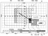
- the operation unit 6 accepts an operation to set a target angle 42Ac of the first arm 23A and a target angle 42Bc of the second arm 23B on an angle dose image 42 displayed on the monitor 4. Then, the movement mechanism 3 moves the first arm 23A and the second arm 23B based on the target angle 42Ac of the first arm 23A and the target angle 42Bc of the second arm 23B set by the operation unit 6. Note that Figs. 13 to 16 show an example in which the target angle 42Ac of the first arm 23A and the target angle 42Bc of the second arm 23B are set by the operation unit 6 on the angle dose image 42 displayed on the monitor 4.
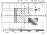
- the operator sets the target angle 42Ac of the first arm 23A by performing an operation on the operation unit 6 to move an icon 42Ab indicating the center of the irradiation axis in the irradiation area of the first X-ray irradiator 21A on the angle dose image 42 displayed on the monitor 4.
- the operator sets the target angle 42Bc of the second arm 23B by performing an operation on the operation unit 6 to move an icon 42Bb indicating the center of the irradiation axis in the irradiation area of the second X-ray irradiator 21B on the angle dose image 42 displayed on the monitor 4.
- the control device 101 controls the movement mechanism 3 to move the first arm 23A and the second arm 23B based on the set target angle 42Ac of the first arm 23A and the set target angle 42Bc of the second arm 23B. That is, the movement mechanism 3 moves the first arm 23A and the second arm 23B based on the set target angle 42Ac of the first arm 23A and the set target angle 42Bc of the second arm 23B by the operation unit 6.
- the irradiation area calculation unit 76 acquires a new first irradiation area display 42Aa and a new second irradiation area display 42Ba each time the angle of the first imaging unit 2A and the angle of the second imaging unit 2B are changed.
- the irradiation area calculation unit 76 is also configured to acquire a new first irradiation area display 42Aa and a new second irradiation area display 42Ba even when the angle of the first imaging unit 2A and the second imaging unit 2B other than the imaging unit angle and the positional relationship with the tabletop 1 are changed.
- the degree of distribution of the X-ray dose in the angle dose image 42 is not changed, and only the first irradiation area display 42Aa and the second irradiation area display 42Ba are moved (changed).
- the color-coded display (colored portion) indicating the magnitude of the X-ray dose in the angle dose image 42 may be displayed semi-transparently to improve the visibility of the first irradiation area display 42Aa and the second irradiation area display 42Ba.
- the first irradiation area display 42Aa and the second irradiation area display 42Ba being moved and the first irradiation area display 42Aa and the second irradiation area display 42Ba at the destination may be displayed in the angle dose image 42.
- the monitor 4 is configured to identifiably display, among multiple angle regions in the angle dose image 42, angle regions for which X-ray irradiation is recommended.
- the image generating unit 75 dose calculation processing unit 70
- the display (coloring) indicating the recommended imaging unit angle (angle region) is displayed on the monitor 4 when the maximum value of the X-ray dose in the angle region included in the irradiation region (irradiation region display 42a) at the current imaging unit angle becomes greater than a predetermined dose (for example, threshold value 43a).
- the recommended imaging section angle (angle area) is selected based on the part of the subject P to be treated or examined from information previously input by the operator, a database stored in the system, or a database acquired through the network. For example, when imaging the blood vessels of the heart, a recommended imaging section angle is set in advance for each type of blood vessel.
- a recommended imaging section angle is set in advance for each type of blood vessel.
- the image generating unit 75 displays the recommended imaging section angle (angle area) set to correspond to the right coronary artery in color in the angle dose image 42.
- the image generating unit 75 displays the imaging unit angles (angle regions) corresponding to each rank in different colors so that the ranks can be identified in the angular dose image 42.
- the imaging unit angles (angle regions) that are recommended may be displayed while excluding regions that already have a high dose.
- the monitor 4 is configured to display a range 42d in which the first arm 23A and the second arm 23B do not interfere with each other on the angle dose image 42 when at least one of the target angle 42Ac of the first arm 23A and the target angle 42Bc of the second arm 23B is set by the operation unit 6.
- the touch panel 5 is configured to display a range 42d in which the first arm 23A and the second arm 23B do not interfere with each other on the angle dose image 42 when at least one of the target angle 42Ac of the first arm 23A and the target angle 42Bc of the second arm 23B is set by the touch panel 5.
- the range 42d in which the first arm 23A and the second arm 23B do not interfere with each other is displayed, for example, by displaying a frame surrounding the non-interference range 42d or by making the color of the non-interference range 42d different from that of other angle regions.
- the monitor 4 is configured to display the range 42d in which the first arm 23A and the second arm 23B do not interfere with each other on the angle dose image 42 when the monitor 4 is in an angle setting mode in which at least one of the target angle 42Ac of the first arm 23A and the target angle 42Bc of the second arm 23B is set, and when an operation is being performed to set at least one of the target angle 42Ac of the first arm 23A and the target angle 42Bc of the second arm 23B.
- the touch panel 5 is configured to display the range 42d in which the first arm 23A and the second arm 23B do not interfere with each other on the angle dose image 42 when the monitor 4 is in an angle setting mode in which at least one of the target angle 42Ac of the first arm 23A and the target angle 42Bc of the second arm 23B is set, and when an operation is being performed to set at least one of the target angle 42Ac of the first arm 23A and the target angle 42Bc of the second arm 23B.
- the angle setting mode is started, for example, when a button (not shown) for transitioning to the angle setting mode is operated.
- the operation for setting at least one of the target angle 42Ac of the first arm 23A and the target angle 42Bc of the second arm 23B is, for example, an operation of moving the icon 42Ab and the icon 42Bb.
- the monitor 4 is configured to display a warning on the angle dose image 42 indicating that at least one of the target angle 42Ac of the first arm 23A and the target angle 42Bc of the second arm 23B set by the operation unit 6 is within the range 42e in which the first arm 23A and the second arm 23B interfere with each other.
- the monitor 4 displays a warning message 42f on the angle dose image 42 indicating that at least one of the target angle 42Ac of the first arm 23A and the target angle 42Bc of the second arm 23B set by the operation unit 6 is within the range 42e in which the first arm 23A and the second arm 23B interfere with each other.
- the touch panel 5 is configured to display a warning on the angle dose image 42 indicating that at least one of the target angle 42Ac of the first arm 23A and the target angle 42Bc of the second arm 23B set by the touch panel 5 is within the range 42e in which the first arm 23A and the second arm 23B interfere with each other.
- the touch panel 5 displays a warning message 42f on the angle dose image 42 indicating that at least one of the target angle 42Ac of the first arm 23A and the target angle 42Bc of the second arm 23B set by the touch panel 5 is in the range 42e in which the first arm 23A and the second arm 23B interfere with each other.
- the monitor 4 is configured to display a warning on the angle dose image 42 indicating that at least one of the target angle 42Ac of the first arm 23A and the target angle 42Bc of the second arm 23B set by the operation unit 6 is in a range in which at least one of the first dose and the second dose exceeds a predetermined threshold value 43b.
- the monitor 4 displays a warning message 42g on the angle dose image 42 indicating that at least one of the target angle 42Ac of the first arm 23A and the target angle 42Bc of the second arm 23B set by the operation unit 6 is in a range in which at least one of the first dose and the second dose exceeds the predetermined threshold value 43b.
- the touch panel 5 is configured to display a warning on the angle dose image 42 indicating that at least one of the target angle 42Ac of the first arm 23A and the target angle 42Bc of the second arm 23B set by the touch panel 5 is in a range in which at least one of the first dose and the second dose exceeds the predetermined threshold value 43b.
- the touch panel 5 displays a warning message 42g on the angle dose image 42 indicating that at least one of the target angle 42Ac of the first arm 23A and the target angle 42Bc of the second arm 23B set by the touch panel 5 is in a range in which at least one of the first dose and the second dose exceeds the predetermined threshold value 43b.
- FIG. 43b Note that FIG.
- 16 shows a case in which at least one of the target angle 42Ac of the first arm 23A and the target angle 42Bc of the second arm 23B set by the operation unit 6 is in a range 42e in which the first arm 23A and the second arm 23B interfere with each other, and in which at least one of the first dose and the second dose exceeds the predetermined threshold value 43b.
- the operating unit 6 is configured to set one of the target angle 42Ac of the first arm 23A and the target angle 42Bc of the second arm 23B on the angle dose image 42 in a range 42d where the first arm 23A and the second arm 23B do not interfere with each other, and then set the other of the target angle 42Ac of the first arm 23A and the target angle 42Bc of the second arm 23B in a range 42d where the first arm 23A and the second arm 23B do not interfere with each other.
- the touch panel 5 is configured to set one of the target angle 42Ac of the first arm 23A and the target angle 42Bc of the second arm 23B in the range 42d where the first arm 23A and the second arm 23B do not interfere with each other on the angle dose image 42, and then set the other of the target angle 42Ac of the first arm 23A and the target angle 42Bc of the second arm 23B in the range 42d where the first arm 23A and the second arm 23B do not interfere with each other. That is, as shown in FIG. 13, the operator first sets the target angle 42Ac of the first arm 23A so that the first arm 23A and the second arm 23B do not interfere with each other. Then, as shown in FIG. 14, the operator next sets the target angle 42Ac of the second arm 23B so that the first arm 23A and the second arm 23B do not interfere with each other.
- the moving mechanism 3 is configured to move the first arm 23A and the second arm 23B based on the target angle 42Ac of the first arm 23A and the target angle 42Bc of the second arm 23B set by the operating unit 6 until the relative positions of the first arm 23A and the second arm 23B are at a position where the first arm 23A and the second arm 23B do not interfere with each other and are close to a position where the first arm 23A and the second arm 23B interfere with each other.
- the movement mechanism 3 is configured to move the first arm 23A and the second arm 23B based on the target angle 42Ac of the first arm 23A and the target angle 42Bc of the second arm 23B set by the touch panel 5 until the relative positions of the first arm 23A and the second arm 23B are in a position where the first arm 23A and the second arm 23B do not interfere with each other and are close to a position where the first arm 23A and the second arm 23B interfere with each other.
- the monitor 4 displays a timeline display 45 for checking the progress of the dose of irradiated X-rays.
- the timeline display 45 is displayed on the monitor 4 based on an input operation on the touch panel 5 or the operation unit 6, for example.
- the X-ray imaging system 100 is configured to cause the monitor 4 to display an angular dose image 42 at a predetermined timing in the past based on a selection operation on the timeline display 45.
- the memory processing unit 77 (dose calculation processing unit 70) is configured to store history information of the distribution of X-ray dose on the surface of the virtual model Pa based on the irradiation of X-rays by the first imaging unit 2A and the irradiation of X-rays by the second imaging unit 2B.
- the memory processing unit 77 stores the history of the irradiated X-ray dose in the storage device of the dose calculation device 102 each time X-ray irradiation by the first imaging unit 2A and the irradiation of X-rays by the second imaging unit 2B are performed.
- the dose calculation processing unit 70 acquires from the storage device history information including the X-ray dose value at the selected predetermined past timing based on an operation to select one of the timings from the time series in the timeline display 45.
- the X-ray imaging system 100 in order to capture an X-ray image 41 as a moving image, X-rays are continuously irradiated over a predetermined period in capturing one X-ray image 41.
- the timeline display 45 a predetermined past timing is displayed in a selectable manner for each predetermined period for generating one X-ray image 41 of a moving image.
- the monitor 4 is configured to display the angular dose image 42 at a predetermined timing in the past based on the history information stored by the memory processing unit 77. That is, based on the stored history information, the distribution of X-ray dose on the surface of the virtual model Pa at the selected predetermined timing in the past and the virtual positional relationship between the first imaging unit 2A and the second imaging unit 2B and the virtual model Pa are acquired. Then, the image generating unit 75 generates the angular dose image 42 based on the X-ray dose value at the predetermined timing in the past by executing a process similar to that for generating the angular dose image 42 at the current time. The generated angular dose image 42 at the predetermined timing in the past is output to the control device 101 and displayed on the monitor 4.
- the memory processing unit 77 may be configured to directly store the generated angular dose image 42 in a storage device for each timing of generation of the X-ray image 41.
- the X-ray imaging system 100 is also configured to display a predicted angular dose image 42 on the monitor 4 based on a selection operation on the timeline display 45.
- the dose prediction unit 78 (dose calculation processing unit 70) is configured to calculate a predicted value of the X-ray dose irradiated by the first imaging unit 2A and a predicted value of the X-ray dose irradiated by the second imaging unit 2B based on the distribution of the X-ray dose on the surface of the virtual model Pa calculated by the model dose calculation unit 72.
- the dose calculation processing unit 70 accepts a selection of a predicted portion of the timeline display 45 (a portion beyond the current timing (current position)) based on an input operation on the touch panel 5 or the operation unit 6.
- the dose prediction unit 78 predicts an increase in the X-ray dose in the case where the X-ray irradiation in the current irradiation area is continued based on the acceptance of the selection of the predicted portion in the timeline display 45.
- the dose prediction unit 78 predicts an increase in the X-ray dose in the case where the irradiation is continued based on, for example, history information.
- the dose prediction unit 78 may also predict an increase in the X-ray dose in the current irradiation area based on a preset database.
- the dose prediction unit 78 may also calculate a predicted value of the X-ray dose when the imaging conditions are changed.
- the dose prediction unit 78 calculates a predicted value of the X-ray dose, thereby calculating a predicted value of the X-ray dose distribution on the surface of the virtual model Pa.
- the monitor 4 is configured to display a predicted angle dose image 42 based on the predicted value predicted by the dose prediction unit 78. That is, the image generation unit 75 generates a predicted angle dose image 42 based on the predicted value of the dose distribution on the surface of the virtual model Pa. The generated predicted angle dose image 42 is then output to the control device 101 and displayed on the monitor 4.
- the touch panel 5 displays the imaging unit angles (the angle of the first imaging unit 2A and the angle of the second imaging unit 2B) in a selectable manner.
- the touch panel 5 also accepts an input operation to change the imaging unit angle.
- the touch panel 5 displays a plurality of imaging unit angle displays 5a as a list so that the imaging unit angle can be selected, based on a database stored in a storage unit such as a flash memory included in the touch panel 5, a storage device of the control device 101, or a storage device of the dose calculation device 102.
- the touch panel 5 also displays a current angle display 5b indicating the current imaging unit angle so that it can be distinguished from the plurality of imaging unit angle displays 5a displayed as a list.
- the touch panel 5 acquires information indicating the positions of the first imaging unit 2A and the second imaging unit 2B from the control device 101.
- the touch panel 5 displays the current imaging unit angle in a visually distinguishable manner by displaying the background of the plurality of imaging unit angle displays 5a displayed as a list in white and the background of the current angle display 5b in blue based on the information acquired from the control device 101.
- the touch panel 5 also displays a non-recommended angle display 5c indicating non-recommended imaging unit angles (angles of the first imaging unit 2A and the second imaging unit 2B) in a visually identifiable manner from among the multiple imaging unit angle displays 5a displayed as a list. Specifically, the touch panel 5 acquires the X-ray dose calculated for each of the multiple angle regions from the dose calculation device 102. The touch panel 5 then displays the non-recommended angle display 5c for imaging unit angles included in an angle region exceeding a predetermined dose (for example, threshold value 43a) from among the imaging unit angles corresponding to the multiple imaging unit angle displays 5a in a visually identifiable manner as non-recommended imaging unit angles. For example, the touch panel 5 displays the non-recommended angle display 5c with a red background to visually identify the non-recommended imaging unit angles.
- a predetermined dose for example, threshold value 43a
- the touch panel 5 also displays a recommended angle display 5d, which is a display (for example, a star mark) indicating the imaging unit angle (the angle of the first imaging unit 2A and the angle of the second imaging unit 2B) at which X-ray irradiation is recommended.
- the recommended imaging unit angle is selected based on the part of the subject P to be treated or examined from information previously input by the operator, a database stored in the system, or a database obtained through the network.
- the touch panel 5 also selectably displays a desired angle display 5e indicating a desired imaging unit angle previously registered by the operator.
- the recommended imaging unit angle and the desired imaging unit angle may be stored in a storage unit such as a flash memory included in the touch panel 5, or may be stored in a storage unit of the control device 101 or a storage unit of the dose calculation device 102.
- the touch panel 5 is configured to display an angular dose image 42. Specifically, the touch panel 5 acquires the angular dose image 42 generated by the image generation unit 75 from the dose calculation device 102. The touch panel 5 is configured to display the acquired angular dose image 42, for example, by switching the display based on an input operation by the operator.
- the monitor 4 displays a three-dimensional image 46 of the inside of the body of the subject P that has been acquired in advance.
- the three-dimensional image 46 is generated by a three-dimensional image generating device 103.
- the three-dimensional image generating device 103 generates the three-dimensional image 46 representing the inside of the body of the subject P based on three-dimensional image data of the inside of the body of the subject P that has been acquired in advance by a CT (Computed Tomography) device or the like.
- the three-dimensional image 46 generated by the three-dimensional image generating device 103 is output from the three-dimensional image generating device 103 to the control device 101, and is displayed on the monitor 4.
- the monitor 4 is configured to identifiably display the X-ray dose in the angle region at the imaging section angle (angle of the first imaging section 2A and angle of the second imaging section 2B) corresponding to the display angle of the displayed three-dimensional image 46.
- the three-dimensional image generating device 103 generates an angle indicator 46a along with the three-dimensional image 46.
- the angle indicator 46a indicates the display angle of the displayed three-dimensional image 46 by indicating the positional relationship between the display showing the subject P, who is the subject, and the display showing the first imaging section 2A and the second imaging section 2B, so as to correspond to the spatial viewpoint (camera position) of the displayed three-dimensional image 46.
- the three-dimensional image generating device 103 acquires the X-ray dose in each of the multiple angle regions from the dose calculation device 102, and causes the angle indicator 46a to identifiably display the magnitude of the acquired X-ray dose.
- the three-dimensional image generating device 103 displays the display indicating the first imaging unit 2A and the second imaging unit 2B in the angle indicator 46a in the same color coding as the angular dose image 42. That is, the three-dimensional image generating device 103 displays the magnitude of the X-ray dose in the angle region including the imaging unit angle corresponding to the current display angle in a distinguishable manner by color coding in the angle indicator 46a.
- the X-ray dose in the angle region including the imaging unit angle corresponding to the current display angle may be displayed by an icon display color coded similar to the angular dose image 42, separately from the angle indicator 46a.
- the monitor 4 (display unit) and the touch panel 5 (display unit) are configured to display the range 42d in which the first arm 23A and the second arm 23B do not interfere with each other on the angle dose image 42 (dose distribution screen) when setting at least one of the target angle 42Ac of the first arm 23A and the target angle 42Bc of the second arm 23B using the operation unit 6 and the touch panel 5 (operation unit).
- This allows the operator to visually recognize the range 42d in which the first arm 23A and the second arm 23B do not interfere with each other when setting at least one of the target angle 42Ac of the first arm 23A and the target angle 42Bc of the second arm 23B on the angle dose image 42 using the operation unit 6 and the touch panel 5.
- This makes it possible to prevent the operator from setting the target angles of the arms so that the two arms interfere with each other while viewing the distribution of the X-ray dose in a configuration with two arms.
- this embodiment has the following additional advantages due to the following configuration:
- the monitor 4 (display unit) and the touch panel 5 (display unit) are configured to display the range 42d in which the first arm 23A and the second arm 23B do not interfere with each other on the angle dose image 42 (dose distribution screen) when the angle setting mode is in which at least one of the target angle 42Ac of the first arm 23A and the target angle 42Bc of the second arm 23B is set, and when an operation is being performed to set at least one of the target angle 42Ac of the first arm 23A and the target angle 42Bc of the second arm 23B.
- the monitor 4 (display unit) and the touch panel 5 (display unit) are configured to display a warning on the angle dose image 42 (dose distribution screen) indicating that at least one of the target angle 42Ac of the first arm 23A and the target angle 42Bc of the second arm 23B set by the operation unit 6 and the touch panel 5 (operation unit) is in the range 42e where the first arm 23A and the second arm 23B interfere with each other when at least one of the target angle 42Ac of the first arm 23A and the target angle 42Bc of the second arm 23B set by the operation unit 6 and the touch panel 5 is in the range 42e where the first arm 23A and the second arm 23B interfere with each other.
- the monitor 4 (display unit) and the touch panel 5 (display unit) display a warning on the angle dose image 42 (dose distribution screen) indicating that at least one of the target angle 42Ac of the first arm 23A and the target angle 42Bc of the second arm 23B set by the operation unit 6 and the touch panel 5 is in the range 42e where the first arm 23A and the second arm 23B interfere with each other.
- a warning is displayed on the angle dose image 42 indicating that at least one of the target angle 42Ac of the first arm 23A and the target angle 42Bc of the second arm 23B set by the operation unit 6 and the touch panel 5 is in a range in which at least one of the first dose and the second dose exceeds the predetermined threshold value 43b.
- the operation unit 6 and the touch panel 5 are configured to set one of the target angle 42Ac of the first arm 23A and the target angle 42Bc of the second arm 23B on the angle dose image 42 (dose distribution screen) in a range 42d where the first arm 23A and the second arm 23B do not interfere with each other, and then set the other of the target angle 42Ac of the first arm 23A and the target angle 42Bc of the second arm 23B in a range 42d where the first arm 23A and the second arm 23B do not interfere with each other.
- the moving mechanism 3 is configured to move the first arm 23A and the second arm 23B based on the target angle 42Ac of the first arm 23A and the target angle 42Bc of the second arm 23B set by the operation unit 6 and the touch panel 5 until the relative positions of the first arm 23A and the second arm 23B are at a position where the first arm 23A and the second arm 23B do not interfere with each other and are close to a position where the first arm 23A and the second arm 23B interfere with each other.
- the moving mechanism 3 moves the first arm 23A and the second arm 23B to the middle of the moving path based on the target angle 42Ac of the first arm 23A and the target angle 42Bc of the second arm 23B set by the operation unit 6 and the touch panel 5.
- the target angle 42Ac of the first arm 23A and the target angle 42Bc of the second arm 23B set by the operation unit 6 and the touch panel 5 again and move the first arm 23A and the second arm 23B again. That is, the examination time of the subject becomes longer. Therefore, it is possible to effectively apply a configuration that can prevent the operator from setting the target angle of the arms so that the two arms interfere with each other while watching the distribution of the X-ray dose.
- the moving mechanism 3 is configured to move the first arm 23A and the second arm 23B based on the target angle 42Ac of the first arm 23A and the target angle 42Bc of the second arm 23B set by the operation unit 6 and the touch panel 5 (operation unit) until the relative positions of the first arm 23A and the second arm 23B are at a position where the first arm 23A and the second arm 23B do not interfere with each other and are close to a position where the first arm 23A and the second arm 23B interfere with each other, even if at least one of the target angle 42Ac of the first arm 23A and the target angle 42Bc of the second arm 23B set by the operation unit 6 and the touch panel 5 (operation unit) is in the range 42e where the first arm 23A and the second arm 23B interfere with each other; however, the present invention is not limited to this.
- the movement mechanism may be configured not to move the first arm and the second arm based on the target angle of the first arm and the target angle of the second arm set by the operation unit when at least one of the target angle of the first arm and the target angle of the second arm set by the operation unit is within a range in which the first arm and the second arm interfere with each other.
- the operation unit 6 and the touch panel 5 are configured to set one of the target angle 42Ac of the first arm 23A and the target angle 42Bc of the second arm 23B in the range 42d where the first arm 23A and the second arm 23B do not interfere with each other on the angle dose image 42 (dose distribution screen), and then set the other of the target angle 42Ac of the first arm 23A and the target angle 42Bc of the second arm 23B in the range 42d where the first arm 23A and the second arm 23B do not interfere with each other, but the present invention is not limited to this.
- the operation unit may be configured to simultaneously set both the target angle of the first arm and the target angle of the second arm on the dose distribution screen in the range where the first arm and the second arm do not interfere with each other.
- the monitor 4 (display unit) and the touch panel 5 (display unit) are configured to display a warning on the angle dose image 42 indicating that at least one of the target angle 42Ac of the first arm 23A and the target angle 42Bc of the second arm 23B set by the operation unit 6 and the touch panel 5 is in a range in which at least one of the first dose, which is the dose of X-rays irradiated by the first X-ray irradiator 21A, and the second dose, which is the dose of X-rays irradiated by the second X-ray irradiator 21B, exceeds a predetermined threshold value 43b.
- the present invention is not limited to this.
- the display unit may be configured not to display the above warning on the angle dose image when at least one of the target angle of the first arm and the target angle of the second arm set by the operation unit is in a range in which at least one of the first dose, which is the dose of X-rays irradiated by the first X-ray irradiator, and the second dose, which is the dose of X-rays irradiated by the second X-ray irradiator, exceeds a predetermined threshold value.
- the monitor 4 (display unit) and the touch panel 5 (display unit) are configured to display a warning on the angle dose image 42 (dose distribution screen) indicating that at least one of the target angle 42Ac of the first arm 23A and the target angle 42Bc of the second arm 23B set by the operation unit 6 is in the range 42e where the first arm 23A and the second arm 23B interfere with each other when at least one of the target angle 42Ac of the first arm 23A and the target angle 42Bc of the second arm 23B set by the operation unit 6 is in the range 42e where the first arm 23A and the second arm 23B interfere with each other, but the present invention is not limited to this.
- the display unit may be configured not to display the warning on the dose distribution screen when at least one of the target angle of the first arm and the target angle of the second arm set by the operation unit is in the range where the first arm and the second arm interfere with each other.
- the monitor 4 (display unit) and the touch panel 5 (display unit) are configured to display the range 42d in which the first arm 23A and the second arm 23B do not interfere with each other on the angle dose image 42 (dose distribution screen) when the angle setting mode is in which at least one of the target angle 42Ac of the first arm 23A and the target angle 42Bc of the second arm 23B is set, and when an operation is being performed to set at least one of the target angle 42Ac of the first arm 23A and the target angle 42Bc of the second arm 23B, but the present invention is not limited to this.
- the display unit may be configured not to display on the dose distribution screen the range in which the first arm and the second arm do not interfere with each other when in an angle setting mode in which at least one of the target angle of the first arm and the target angle of the second arm is set, or may be configured not to display on the dose distribution screen the range in which the first arm and the second arm do not interfere with each other when an operation is being performed to set at least one of the target angle of the first arm and the target angle of the second arm.
- a first arm that supports, in opposing relation to each other, a first X-ray irradiator having an X-ray source that irradiates X-rays and a first X-ray detection unit that detects the X-rays irradiated from the first X-ray irradiator; a second arm supporting a second X-ray irradiating unit having the X-ray source and a second X-ray detecting unit that detects X-rays irradiated from the second X-ray irradiating unit in opposing relation to each other; a display unit that displays an angle of the first arm and an angle of the second arm, and a dose distribution screen including a first dose distribution which is a dose of X-rays irradiated by the first X-ray irradiator, a second dose distribution which is a dose of X-rays irradiated by the second X-ray irradiator, a first dose distribution which is
- (Item 2) 2. The X-ray imaging system according to item 1, wherein the display unit is configured to display on the dose distribution screen a range within which the first arm and the second arm do not interfere with each other when the display unit is in an angle setting mode in which at least one of a target angle of the first arm and a target angle of the second arm is set, and when an operation for setting at least one of a target angle of the first arm and a target angle of the second arm is being performed.
- (Item 3) The X-ray imaging system according to item 1 or 2, wherein the display unit is configured to, when at least one of the target angle of the first arm and the target angle of the second arm set by the operation unit is within a range in which the first arm and the second arm interfere with each other, display a warning on the dose distribution screen indicating that at least one of the target angle of the first arm and the target angle of the second arm set by the operation unit is within a range in which the first arm and the second arm interfere with each other.
- (Item 4) Item 3. The X-ray imaging system according to item 3, wherein the display unit is configured to display, when at least one of the target angle of the first arm and the target angle of the second arm set by the operation unit is in a range where the first arm and the second arm interfere with each other, a warning indicating that at least one of the target angle of the first arm and the target angle of the second arm set by the operation unit is in a range where the first arm and the second arm interfere with each other, on the dose distribution screen; and, when at least one of the target angle of the first arm and the target angle of the second arm set by the operation unit is in a range where at least one of a first dose that is a dose of X-rays irradiated by the first X-ray irradiator and a second dose that is a dose of X-rays irradiated by the second X-ray irradiator exceeds a predetermined threshold value, a warning indicating that at least one of the target angle of the first arm
- (Item 5) The X-ray imaging system according to any one of items 1 to 4, wherein the operation unit is configured to set, on the dose distribution screen, one of the target angle of the first arm and the target angle of the second arm within a range in which the first arm and the second arm do not interfere with each other, and then set the other of the target angle of the first arm and the target angle of the second arm within a range in which the first arm and the second arm do not interfere with each other.
- (Item 6) The X-ray imaging system according to any one of items 1 to 5, wherein the movement mechanism is configured to move the first arm and the second arm based on the target angle of the first arm and the target angle of the second arm set by the operation unit, even if at least one of the target angle of the first arm and the target angle of the second arm set by the operation unit is within a range in which the first arm and the second arm interfere with each other, until the relative positions of the first arm and the second arm are at a position where the first arm and the second arm do not interfere with each other and are close to a position where the first arm and the second arm interfere with each other.
- Movement mechanism Display unit 5 Touch panel (display unit, operation unit) 6 Operation unit 21A First X-ray irradiation unit 22A First X-ray detection unit 21B Second X-ray irradiation unit 22B Second X-ray detection unit 23A First arm 23B Second arm 42 Angular dose image (dose distribution screen) 42Aa First illumination area display (first illumination range) 42Ac Target angle of first arm 42Ba Second irradiation area display (second irradiation range) 42Bc: target angle of the second arm; 42d: range in which the first arm and the second arm do not interfere with each other; 42e: range in which the first arm and the second arm interfere with each other; 43b: predetermined threshold value; 100: X-ray imaging system
Landscapes
- Health & Medical Sciences (AREA)
- Life Sciences & Earth Sciences (AREA)
- Medical Informatics (AREA)
- Engineering & Computer Science (AREA)
- Radiology & Medical Imaging (AREA)
- Biomedical Technology (AREA)
- Biophysics (AREA)
- Nuclear Medicine, Radiotherapy & Molecular Imaging (AREA)
- Optics & Photonics (AREA)
- Pathology (AREA)
- Physics & Mathematics (AREA)
- High Energy & Nuclear Physics (AREA)
- Heart & Thoracic Surgery (AREA)
- Molecular Biology (AREA)
- Surgery (AREA)
- Animal Behavior & Ethology (AREA)
- General Health & Medical Sciences (AREA)
- Public Health (AREA)
- Veterinary Medicine (AREA)
- Apparatus For Radiation Diagnosis (AREA)
Priority Applications (2)
| Application Number | Priority Date | Filing Date | Title |
|---|---|---|---|
| JP2025537703A JPWO2025028024A1 (https=) | 2023-08-01 | 2024-06-06 | |
| CN202480049917.2A CN121620329A (zh) | 2023-08-01 | 2024-06-06 | X射线摄影系统 |
Applications Claiming Priority (2)
| Application Number | Priority Date | Filing Date | Title |
|---|---|---|---|
| JP2023125864 | 2023-08-01 | ||
| JP2023-125864 | 2023-08-01 |
Publications (1)
| Publication Number | Publication Date |
|---|---|
| WO2025028024A1 true WO2025028024A1 (ja) | 2025-02-06 |
Family
ID=94394407
Family Applications (1)
| Application Number | Title | Priority Date | Filing Date |
|---|---|---|---|
| PCT/JP2024/020729 Pending WO2025028024A1 (ja) | 2023-08-01 | 2024-06-06 | X線撮影システム |
Country Status (3)
| Country | Link |
|---|---|
| JP (1) | JPWO2025028024A1 (https=) |
| CN (1) | CN121620329A (https=) |
| WO (1) | WO2025028024A1 (https=) |
Citations (5)
| Publication number | Priority date | Publication date | Assignee | Title |
|---|---|---|---|---|
| US20110317815A1 (en) * | 2010-06-29 | 2011-12-29 | Philipp Bernhardt | Method for Visualizing a Patient Dose, Computer Program Product and X-Ray Apparatus |
| JP2015500119A (ja) * | 2011-12-14 | 2015-01-05 | コーニンクレッカ フィリップス エヌ ヴェ | 高線量cアーチ幾何学的位置を防ぐためのリアルタイム・フィードバック |
| JP2015096179A (ja) * | 2013-11-15 | 2015-05-21 | 株式会社東芝 | X線診断装置および線量分布表示方法 |
| JP2019122767A (ja) * | 2018-01-15 | 2019-07-25 | キヤノンメディカルシステムズ株式会社 | 医用情報処理装置、x線診断システム及び医用情報処理プログラム |
| JP2021065387A (ja) * | 2019-10-21 | 2021-04-30 | 株式会社島津製作所 | X線透視撮影装置 |
-
2024
- 2024-06-06 WO PCT/JP2024/020729 patent/WO2025028024A1/ja active Pending
- 2024-06-06 JP JP2025537703A patent/JPWO2025028024A1/ja active Pending
- 2024-06-06 CN CN202480049917.2A patent/CN121620329A/zh active Pending
Patent Citations (5)
| Publication number | Priority date | Publication date | Assignee | Title |
|---|---|---|---|---|
| US20110317815A1 (en) * | 2010-06-29 | 2011-12-29 | Philipp Bernhardt | Method for Visualizing a Patient Dose, Computer Program Product and X-Ray Apparatus |
| JP2015500119A (ja) * | 2011-12-14 | 2015-01-05 | コーニンクレッカ フィリップス エヌ ヴェ | 高線量cアーチ幾何学的位置を防ぐためのリアルタイム・フィードバック |
| JP2015096179A (ja) * | 2013-11-15 | 2015-05-21 | 株式会社東芝 | X線診断装置および線量分布表示方法 |
| JP2019122767A (ja) * | 2018-01-15 | 2019-07-25 | キヤノンメディカルシステムズ株式会社 | 医用情報処理装置、x線診断システム及び医用情報処理プログラム |
| JP2021065387A (ja) * | 2019-10-21 | 2021-04-30 | 株式会社島津製作所 | X線透視撮影装置 |
Also Published As
| Publication number | Publication date |
|---|---|
| CN121620329A (zh) | 2026-03-06 |
| JPWO2025028024A1 (https=) | 2025-02-06 |
Similar Documents
| Publication | Publication Date | Title |
|---|---|---|
| JP6768878B2 (ja) | 画像表示の生成方法 | |
| JP6876065B2 (ja) | 放射線照射を低減された手術中の3次元視覚化 | |
| US9138197B2 (en) | Selection of optimal viewing angle to optimize anatomy visibility and patient skin dose | |
| CN107019522B (zh) | 对操作者提供图像支持的x射线装置和数据载体 | |
| JP2016198262A (ja) | X線診断装置 | |
| US20170135654A1 (en) | Automatic or assisted region of interest positioning in x-ray diagnostics and interventions | |
| US10993690B2 (en) | Medical apparatus and x-ray system | |
| JP5405010B2 (ja) | 画像表示装置及び画像表示方法 | |
| JP6687393B2 (ja) | 医用画像診断装置 | |
| JP7806816B2 (ja) | X線撮影システム | |
| JP7412908B2 (ja) | 吸収線量管理装置及び吸収線量管理方法 | |
| WO2025028024A1 (ja) | X線撮影システム | |
| US12605217B2 (en) | X-ray imaging system and device display method | |
| US11147526B2 (en) | X-ray imaging apparatus | |
| JP5458207B2 (ja) | 画像表示装置及び画像表示方法 | |
| JP5269233B2 (ja) | X線診断装置 | |
| JP7509030B2 (ja) | X線撮影装置、および、画像処理方法 | |
| US20240127450A1 (en) | Medical image processing apparatus and non-transitory computer readable medium | |
| JP2025078423A (ja) | 医用画像処理装置、x線診断装置及び医用画像処理プログラム | |
| CN118715043A (zh) | 医用图像处理装置、治疗系统、医用图像处理方法、程序及存储介质 |
Legal Events
| Date | Code | Title | Description |
|---|---|---|---|
| 121 | Ep: the epo has been informed by wipo that ep was designated in this application |
Ref document number: 24848685 Country of ref document: EP Kind code of ref document: A1 |
|
| ENP | Entry into the national phase |
Ref document number: 2025537703 Country of ref document: JP Kind code of ref document: A |
|
| WWE | Wipo information: entry into national phase |
Ref document number: 2025537703 Country of ref document: JP |
|
| NENP | Non-entry into the national phase |
Ref country code: DE |