US10993690B2 - Medical apparatus and x-ray system - Google Patents
Medical apparatus and x-ray system Download PDFInfo
- Publication number
- US10993690B2 US10993690B2 US16/016,905 US201816016905A US10993690B2 US 10993690 B2 US10993690 B2 US 10993690B2 US 201816016905 A US201816016905 A US 201816016905A US 10993690 B2 US10993690 B2 US 10993690B2
- Authority
- US
- United States
- Prior art keywords
- ray
- suitability
- target site
- suitability level
- irradiating direction
- Prior art date
- Legal status (The legal status is an assumption and is not a legal conclusion. Google has not performed a legal analysis and makes no representation as to the accuracy of the status listed.)
- Active, expires
Links
Images


Classifications
-
- A—HUMAN NECESSITIES
- A61—MEDICAL OR VETERINARY SCIENCE; HYGIENE
- A61B—DIAGNOSIS; SURGERY; IDENTIFICATION
- A61B6/00—Apparatus for radiation diagnosis, e.g. combined with radiation therapy equipment
- A61B6/54—Control of apparatus or devices for radiation diagnosis
- A61B6/542—Control of apparatus or devices for radiation diagnosis involving control of exposure
-
- A—HUMAN NECESSITIES
- A61—MEDICAL OR VETERINARY SCIENCE; HYGIENE
- A61B—DIAGNOSIS; SURGERY; IDENTIFICATION
- A61B6/00—Apparatus for radiation diagnosis, e.g. combined with radiation therapy equipment
- A61B6/10—Application or adaptation of safety means
- A61B6/107—Protection against radiation, e.g. shielding
-
- A—HUMAN NECESSITIES
- A61—MEDICAL OR VETERINARY SCIENCE; HYGIENE
- A61B—DIAGNOSIS; SURGERY; IDENTIFICATION
- A61B6/00—Apparatus for radiation diagnosis, e.g. combined with radiation therapy equipment
- A61B6/42—Apparatus for radiation diagnosis, e.g. combined with radiation therapy equipment with arrangements for detecting radiation specially adapted for radiation diagnosis
- A61B6/4291—Apparatus for radiation diagnosis, e.g. combined with radiation therapy equipment with arrangements for detecting radiation specially adapted for radiation diagnosis the detector being combined with a grid or grating
-
- A—HUMAN NECESSITIES
- A61—MEDICAL OR VETERINARY SCIENCE; HYGIENE
- A61B—DIAGNOSIS; SURGERY; IDENTIFICATION
- A61B6/00—Apparatus for radiation diagnosis, e.g. combined with radiation therapy equipment
- A61B6/44—Constructional features of apparatus for radiation diagnosis
- A61B6/4429—Constructional features of apparatus for radiation diagnosis related to the mounting of source units and detector units
- A61B6/4435—Constructional features of apparatus for radiation diagnosis related to the mounting of source units and detector units the source unit and the detector unit being coupled by a rigid structure
- A61B6/4441—Constructional features of apparatus for radiation diagnosis related to the mounting of source units and detector units the source unit and the detector unit being coupled by a rigid structure the rigid structure being a C-arm or U-arm
-
- A—HUMAN NECESSITIES
- A61—MEDICAL OR VETERINARY SCIENCE; HYGIENE
- A61B—DIAGNOSIS; SURGERY; IDENTIFICATION
- A61B6/00—Apparatus for radiation diagnosis, e.g. combined with radiation therapy equipment
- A61B6/46—Apparatus for radiation diagnosis, e.g. combined with radiation therapy equipment with special arrangements for interfacing with the operator or the patient
- A61B6/461—Displaying means of special interest
- A61B6/465—Displaying means of special interest adapted to display user selection data, e.g. graphical user interface, icons or menus
-
- A—HUMAN NECESSITIES
- A61—MEDICAL OR VETERINARY SCIENCE; HYGIENE
- A61B—DIAGNOSIS; SURGERY; IDENTIFICATION
- A61B6/00—Apparatus for radiation diagnosis, e.g. combined with radiation therapy equipment
- A61B6/50—Clinical applications
- A61B6/504—Clinical applications involving diagnosis of blood vessels, e.g. by angiography
-
- G—PHYSICS
- G01—MEASURING; TESTING
- G01T—MEASUREMENT OF NUCLEAR OR X-RADIATION
- G01T1/00—Measuring X-radiation, gamma radiation, corpuscular radiation, or cosmic radiation
- G01T1/16—Measuring radiation intensity
- G01T1/17—Circuit arrangements not adapted to a particular type of detector
-
- G—PHYSICS
- G01—MEASURING; TESTING
- G01T—MEASUREMENT OF NUCLEAR OR X-RADIATION
- G01T1/00—Measuring X-radiation, gamma radiation, corpuscular radiation, or cosmic radiation
- G01T1/29—Measurement performed on radiation beams, e.g. position or section of the beam; Measurement of spatial distribution of radiation
- G01T1/2907—Angle determination; Directional detectors; Telescopes
-
- G—PHYSICS
- G01—MEASURING; TESTING
- G01T—MEASUREMENT OF NUCLEAR OR X-RADIATION
- G01T1/00—Measuring X-radiation, gamma radiation, corpuscular radiation, or cosmic radiation
- G01T1/29—Measurement performed on radiation beams, e.g. position or section of the beam; Measurement of spatial distribution of radiation
- G01T1/2914—Measurement of spatial distribution of radiation
Definitions
- An embodiment as an aspect of the present invention relates to a medical apparatus and an X-ray system.
- DTS dose tracking system
- AFM arteriovenous malformation
- CAS carotid artery stenting
- PCI coronary artery percutaneous coronary intervention
- TAVR transcatheter aortic valve replacement
- TACE transcatheter arterial chemo-embolization
- the planning apparatus of the prior art can determine the X-ray irradiating direction in consideration of the cumulative dose of the patient using the DTS at the time of treatment planning.
- FIG. 1 is a schematic diagram showing a configuration of an X-ray system according to a first embodiment
- FIG. 2 is a perspective view showing an appearance of an imaging apparatus provided in the X-ray system according to the first embodiment
- FIG. 3 is a diagram showing an example of the cumulative dose distribution in the X-ray system according to the first embodiment
- FIG. 4 is a diagram for showing details of the cumulative dose distribution in the X-ray system according to the first embodiment
- FIG. 5 is a block diagram showing functions of the X-ray system according to the first embodiment
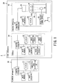
- FIG. 6 is a flowchart showing an operation of the X-ray system according to the first embodiment
- FIG. 7 is a table showing a primary suitability level of each index corresponding to each X-ray irradiating direction in the X-ray system according to the first embodiment
- FIG. 8 is a table showing a secondary suitability level of overall indexes corresponding to each X-ray irradiating direction in the X-ray system according to the first embodiment
- FIGS. 9A to 9C are diagrams showing a third example of an X-ray irradiating direction selection screen in the X-ray system according to the first embodiment
- FIG. 10 is a diagram showing a fourth example of an X-ray irradiating direction selection screen in the X-ray system according to the first embodiment
- FIG. 11 is a diagram showing a fifth example of the X-ray irradiating direction selection screen in the X-ray system according to the first embodiment
- FIG. 12 is a diagram showing a sixth example of the X-ray irradiating direction selection screen in the X-ray system according to the first embodiment
- FIGS. 13A and 13B is a diagram for explaining a method of calculating the primary suitability level of an index “cumulative dose of patient” in the X-ray system according to the first embodiment
- FIGS. 14A and 14B are diagrams for explaining a method of calculating the primary suitability of the index “cumulative dose of patient” in the X-ray system according to the first embodiment
- FIG. 15 is a diagram for explaining a method of calculating the primary suitability level of the index “visibility of treatment target site” in the X-ray system according to the first embodiment
- FIGS. 16A and 16B is a diagram for explaining a method of calculating the primary suitability level of the index “exposure dose of surrounding person” in the X-ray system according to the first embodiment
- FIG. 17 is a block diagram showing functions of an X-ray system according to a second embodiment
- FIGS. 18 and 19 is a flowchart showing an operation of the X-ray system according to the second embodiment
- FIGS. 20A to 20D is a diagram showing a display example of the primary suitability level corresponding to the current X-ray irradiating direction in the X-ray system according to the second embodiment.
- FIG. 21 is a top view showing a movement space of a surrounding person in a modified example of the X-ray systems according to the first and second embodiments.
- a medical apparatus includes control circuitry.
- the control circuitry is configured to: acquire a three-dimensional cumulative dose distribution of an object; set a treatment target site by treatment accompanied with X-ray irradiation to the object; and determine an X-ray irradiating direction for performing the X-ray irradiation based on the three-dimensional cumulative dose distribution and the treatment target site.
- FIG. 1 is a schematic diagram showing a configuration of an X-ray system according to a first embodiment.
- FIG. 2 is a perspective view showing an appearance of an imaging apparatus provided in the X-ray system according to the first embodiment.
- FIGS. 1 and 2 show an X-ray system 1 according to a first embodiment.
- the X-ray system 1 includes a planning apparatus 10 and an X-ray apparatus 20 .
- the planning apparatus 10 is installed outside a treatment room and a control room.
- the X-ray apparatus 20 is an apparatus such as an angiography apparatus or an X-ray fluoroscopic imaging apparatus, and has a console 30 and an imaging apparatus 40 .
- the console 30 of the X-ray apparatus 20 is installed in the control room adjacent to the treatment room.
- the imaging apparatus 40 of the X-ray apparatus 20 is installed in the treatment room.
- the planning apparatus 10 is a medical apparatus connected to the console 30 of the X-ray apparatus 20 so as to be able to communicate with each other via a network such as a local area network (LAN) of the hospital backbone.
- the planning apparatus 10 includes control circuitry 11 , a main memory 12 , an input interface 13 , a display 14 , a cumulative dose distribution data base (DB) 15 and the like.
- the control circuitry 11 means any one of dedicated or general central processing unit (CPU) and a micro processor unit (MPU), an application specific integrated circuit (ASIC), and a programmable logic device.
- the programmable logic device may be, for example, any one of a simple programmable logic device (SPLD), a complex programmable logic device (CPLD), a field programmable gate array (FPGA) and the like.
- SPLD simple programmable logic device
- CPLD complex programmable logic device
- FPGA field programmable gate array
- the control circuitry 11 may be a single circuit or a combination of separate circuits.
- the main memory 12 which stores the programs, may be separately provided for each of the circuits.
- a single main memory 12 may store the programs corresponding to the functions of the multiple circuits.
- the main memory 12 is constituted by a semiconductor memory element such as a random access memory (RAM), a flash memory, a hard disk, an optical disk, and the like.
- the main memory 12 may be constituted by a portable medium such as a universal serial bus (USB) memory and a digital video disk (DVD).
- the main memory 12 stores various processing programs (including an operating system (OS) and the like besides the application program) used in the control circuitry 11 and data necessary for executing the programs.
- the OS may include a graphical user interface (GUI) that allows graphics to be used to display information on the display 14 corresponding to the operator and a basic operation can be performed by the input interface 13 .
- GUI graphical user interface
- the input interface 13 includes an input device operable by the operator, and an input circuit for inputting a signal from the input device.
- the input device includes a pointing device (for example, a mouse), a keyboard, various buttons, and the like.
- the input circuit generates, when the input device is operated by the operator, an input signal corresponding to the operation, and outputs it to the control circuitry 11 .
- the planning apparatus 10 may include a touch panel in which the input device is integrated with the display 14 .
- the display 14 is a display device such as a liquid crystal display panel, a plasma display panel, and an organic electro luminescence (EL) panel.
- the display 14 displays the image data generated under the control of the control circuitry 11 .
- the cumulative dose distribution DB 15 is a storage configured with the HDD, the memory, or the like.
- the cumulative dose distribution DB 15 can register data of cumulative dose distribution showing the distribution of patient identification information (patient ID) for identifying a patient such as the patient U, and of the three-dimensional integrated dose (mGy) in the body surface of each patient.
- patient ID patient identification information
- MGy three-dimensional integrated dose
- the cumulative dose distribution is an integrated value of exposure dose generated by unit patient and unit procedure.
- examples of procedures of the treatment accompanied with the X-ray irradiation are treatment of arteriovenous malformation (AVM), carotid artery stenting (CAS), coiling corresponding to unruptured cerebral artery aneurysm, coronary artery percutaneous coronary intervention (PCI), transcatheter aortic valve replacement (TAVR), and transcatheter arterial chemo-embolization (TACE) or the like.
- AVM arteriovenous malformation
- CAS carotid artery stenting
- PCI coronary artery percutaneous coronary intervention
- TAVR transcatheter aortic valve replacement
- TACE transcatheter arterial chemo-embolization
- FIG. 3 is a diagram showing an example of the cumulative dose distribution in the X-ray system 1 .
- the cumulative dose distribution DB 15 (shown in FIG. 1 ) can store multiple cumulative dose distributions where cumulative doses in a model coordinate system are associated with respective body surface positions of a three-dimensional human body model. Each cumulative dose distribution is accompanied by the patient identifying information contained in patient information (for example, patients U and V).
- FIG. 3 shows the case where mapping of the cumulative doses to the body surface positions of the human body model is stored as the cumulative dose distribution.
- data on the human body model, and the cumulative doses on the body surface positions may be separately stored.
- volume data that has already been generated and encompasses the entire patient may be used.
- FIG. 4 is a diagram for showing details of the cumulative dose distribution in the X-ray system 1 .
- the cumulative dose distribution in the human body model coordinate system is based on the cumulative doses on the body surface positions (points) Q 1 to Q 6 in the human body model.
- the body surface positions Q 1 to Q 6 are associated with information on the X coordinate, Y coordinate, Z coordinate, and cumulative dose (mGy).
- the X coordinate corresponds to the lateral direction of the patient.
- the Y coordinate corresponds to the ventrodorsad direction of the patient.
- the Z coordinate corresponds to the body axis direction of the patient.
- the cumulative doses on the body surface positions may be registered separately from or together with the human body model. In the case with no exposure dose (body surface positions Q 1 to Q 6 ), the cumulative dose is 0 mGy.
- the planning apparatus 10 generates, based on the operations of the control circuitry 11 , the main memory 12 , the input interface 13 , the display 14 and the cumulative dose distribution DB 15 , planned data in accordance with indexes “cumulative dose of patient”, “visibility of treatment target site” and “exposure dose of surrounding person”.
- the planning apparatus 10 generates the planned data based on data such as volume data generated by imaging the patient and on operation input by the operator (hereinafter referred to as “planner”) of the planning apparatus 10 .
- the volume data used in the planning apparatus 10 is data generated in advance by an imaging apparatus (not shown) that can visualize the internal structure of the patient.
- the volume data is an aggregate of voxels arranged in a three-dimensional direction.
- the imaging apparatus includes an X-ray diagnostic apparatus, an X-ray computed tomography (CT) apparatus, a magnetic resonance imaging (MRI) apparatus, a positron emission tomography (PET) apparatus, a single photon emission computed tomography (SPECT) and the like.
- CT computed tomography
- MRI magnetic resonance imaging
- PET positron emission tomography
- SPECT single photon emission computed tomography
- the console 30 of the X-ray apparatus 20 is a medical apparatus connected to the planning apparatus 10 via a network such as the LAN of the hospital backbone so as to be mutually communicable.
- the console 30 includes a control circuitry 31 , a main memory 32 , an input interface 33 , a display 34 , an image generating circuit 35 , an image processing circuit 36 , an image memory 37 and the like, and controls the operation of the imaging apparatus 40 .
- the image generating circuit 35 performs, under the control of the control circuitry 31 , logarithmic transformation processing (LOG processing) on the projection data output from the imaging apparatus 40 , performs addition processing as necessary, thereby generating X-ray image data.
- the image processing circuit 36 performs, under the control of the control circuitry 31 , image processing on the X-ray image data generated by the image generating circuit 35 .
- the image processing includes enlargement/gradation/spatial filter processing corresponding to the data, minimum value/maximum value tracing processing of the data accumulated in time series, addition processing for removing noise, and the like.
- the image memory 37 is a storage constituted by a semiconductor memory element such as the RAM, the flash memory or the like, the hard disk, the optical disk, or the like.
- the image memory 37 stores, under the control of the control circuitry 31 , the X-ray image data after image processing by the image processing circuit 36 .
- the imaging apparatus 40 of the X-ray apparatus 20 is connected to the console apparatus 30 , and is a medical apparatus capable of performing X-ray imaging by performing the X-ray irradiation on the patient U.
- the imaging apparatus 40 is provided with an imaging controller 41 , an input interface 43 , a display 44 , an X-ray irradiator 45 , an X-ray detector 46 , a C-arm 47 (shown in FIG. 2 ), a high voltage power supply 48 and a bed 49 .
- the X-ray imaging includes imaging in which X-rays are irradiated continuously or intermittently (pulse), so-called “fluoroscopy”, and one shot of the X-ray irradiation, so-called “radiography”.
- the imaging apparatus 40 may be any device as long as it can perform X-ray imaging, in the case of being an angio system, the case of being an X-ray TV system, and the like.
- FIGS. 1 and 2 show a case where the imaging apparatus 40 is of an under-tube type. However, it may be an over-tube type.
- the input circuit 43 and the display 44 of the imaging apparatus 40 have the same configurations as the input interface 13 and the display 14 of the planning apparatus 10 , respectively, and the descriptions thereof will be omitted.
- the display 44 can display the X-ray image data generated by the console 30 by X-ray imaging as an X-ray image.
- the practitioner D such as a doctor can proceed with the treatment while viewing the X-ray image displayed on the display 44 in substantially real time.
- the imaging controller 41 includes a control circuitry and a main memory (not shown).
- the control circuitry and the main memory have the same configurations as the control circuitry 11 and the main memory 12 of the planning apparatus 10 , respectively, and the descriptions thereof will be omitted.
- the imaging controller 41 controls, under the control of the console 30 , operations of the X-ray irradiator 45 , the X-ray detector 46 , the C-arm 47 , the high voltage power supply 48 , and the bed 49 for X-ray imaging.
- the X-ray irradiator 45 is provided at one end of the C-arm 47 . Under the control of the imaging controller 41 , so that movement in a direction of changing a source image receiving distance (SID), that is, forward and backward movement is possible.
- the X-ray irradiator 45 is provided with an X-ray source (for example, an X-ray tube) and a movable diaphragm, as not shown in drawings.
- the X-ray tube receives high voltage power from the high voltage power supply 48 , and generates X-rays according to the condition of high voltage power.
- the movable diaphragm movably supports a diaphragm blade (also called “leaf”) constituted by a material which shields X-rays at the X-ray irradiation port of the X-ray tube.
- a linear quality adjustment filter (not shown) for adjusting the quality of X-rays generated by the X-ray tube may be provided on the front of the X-ray tube.
- the X-ray detector 46 is provided at one end of the C-arm 47 so as to face the X-ray irradiator 45 .
- the X-ray detector 46 is provided so as to be able to move back and forth under the control of the imaging controller 41 .
- the X-ray detector 46 includes a flat panel detector (FPD) and an analog to digital (A/D) conversion circuit, as not shown in drawings.
- the FPD has detecting elements arranged two-dimensionally. Between each detecting element of the FPD, the scanning line and the signal line are disposed so as to be orthogonal to each other.
- a grid (not shown) may be provided on the front face of the FPD. In order to absorb the scattered ray incident on the FPD and improve the contrast of the X-ray image, the grid is formed by alternately arranging a grid plate formed of lead or the like having a large X-ray absorption and a grid plate formed of aluminum, wood or the like which is easy to transmit X-rays.
- the A/D conversion circuit converts the projection data of the time-series analog signal (video signal) output from the FPD into a digital signal, and outputs it to the console 30 via the imaging controller 41 .
- the X-ray detector 46 may be an image intensifier (I. I.)-TV system.
- the I. I.-TV system converts the X-rays transmitted through a subject, for example, patient U, and directly incident X-rays into visible light, thereby doubling the luminance in the process of light-electron-light conversion to generate projection data with high sensitivity. Then, the I. I.-TV system converts optical projection data to electric signals using a charge coupled device (CCD) imaging device, and converts the projection data of time series analog signals (video signals) into digital signals.
- CCD charge coupled device
- the C-arm 47 is supported on the ceiling or the floor so as to be rotatable in the left-right direction and the head-foot direction under predetermined restriction with respect to each of the XYZ directions orthogonal to each other. Therefore, it is possible for the C-arm 47 to freely change the X-ray irradiating direction corresponding to the treatment target site of the patient U.
- a straight line passing through the center of the detection surface of the X-ray detector from the X-ray focal point of the X-ray tube is defined as an X-ray irradiating direction (also called “working angle”) AG (shown in FIG. 2 ).
- the X-ray irradiating direction AG is determined by (1) a rotation angle of the C-arm 47 , that is, a rotation angle by a rotation in a left-right direction and (2) a rotation angle by a rotation in a cranial direction.
- the rotation angle of the C-arm 47 in the left-right direction is determined by RAO (Right Anterior Oblique) and LAO (Left Anterior Oblique), and the rotation angle of the C-arm 47 in the cranial direction is CRA (Cranial) and CAU (Caudal).
- the high voltage power supply 48 is, under the control of the imaging controller 41 , capable of supplying high voltage power to the X-ray tube of the X-ray irradiator 45 .
- the bed 49 is supported on the floor surface and supports the table 491 .
- the bed 49 can perform sliding (move in the X axis, Y axis and Z axis directions) or rolling movement with respect to the table 491 under the control of the imaging controller 41 .
- the table 491 is capable of placing the patient U thereon.
- FIG. 5 is a block diagram showing functions of the X-ray system 1 .
- the control circuitry 11 of the planning apparatus 10 executes a program, thereby achieving an acquiring function 51 , a calculating function 52 and a determining function 53 .
- the description is made assuming that the functions 51 to 53 function as software. Alternatively, all or some of the functions 51 to 53 may be implemented as hardware such as the ASIC in the planning apparatus 10 .
- the acquiring function 51 includes a function of acquiring a three-dimensional cumulative dose distribution (shown in FIG. 3 , hereinafter simply referred to as “cumulative dose distribution”) of the patient U from the cumulative dose distribution DB 15 .
- the calculating function 52 includes a function of calculating multiple rotation angles of the C-arm 47 , that is, multiple working angles corresponding to multiple X-ray irradiating directions, as quantitative values.
- the calculating function 52 has a patient dose calculating function 52 a , a visibility calculating function 52 b , a surrounding dose calculating function 52 c and a suitability calculating function 52 d.
- the method for calculating the primary suitability level of the index “cumulative dose of patient” will be described later with reference to FIGS. 13A, 13B, 14A and 14B .
- the index “visibility of treatment target site” means the visibility of the treatment target site in the X-ray image, and is quantified based on not only the structure of the treatment target site but also the content of the procedure when treating the treatment target site (during the treatment etc.).
- the method for calculating the primary suitability level of the index “visibility of treatment target site” will be described later with reference to FIG. 15 .
- the method for calculating the primary suitability level of the index “exposure dose of surrounding person” will be described later with reference to FIGS. 16A and 16B .
- the surrounding person means a person to be stayed in the treatment room in the treatment accompanying the X-ray irradiation of the patient U.
- the surrounding person includes at least one of the practitioner D (shown in FIG. 2 ) such as a doctor performing the treatment, an operator S (shown in FIG. 2 ) for performing a rotating operation or the like of the C-arm 47 during the treatment, and a nurse N (shown in FIG. 2 ) for supporting the treatment.
- the suitability calculating function 52 d includes a function of calculating, based on at least one of the primary suitability levels of the index “cumulative dose of patient”, the index “visibility of treatment target site” and the index “exposure dose of surrounding person”, a secondary suitability level of overall indexes, corresponding to each X-ray irradiating direction.
- the primary suitability level of the index “cumulative dose of patient” corresponds to each X-ray irradiating direction calculated by the patient dose calculating function 52 a .
- the primary suitability level of the index “visibility of treatment target site” corresponds to each X-ray irradiating direction calculated by the visibility calculating function 52 b .
- the primary suitability level of the index “exposure dose of surrounding person” corresponds to each X-ray irradiating direction calculated by the surrounding dose calculating function 52 c.
- the determining function 53 has a function of determining an X-ray irradiating direction for performing the X-ray irradiation, based on the three-dimensional cumulative dose distribution acquired by the acquiring function 51 and at least the treatment target site set by the visibility calculating function 52 b . Specifically, the determining function 53 provides each X-ray irradiating direction and a suitability level (primary or secondary suitability level) corresponding to each X-ray irradiating direction, the suitability level being calculated by the calculating function 52 . Therefore, it is possible for the planner to select the X-ray irradiating direction corresponding to the predetermined suitability level from the multiple suitability levels provided, for example, displayed.
- the determining function 53 determines the selected X-ray irradiating direction as an appropriate X-ray irradiating direction for the X-ray irradiation. Planed data is generated according to the determined X-ray irradiating direction.
- FIG. 6 is a flowchart showing an operation of the X-ray system 1 .
- the secondary suitability level of overall indexes is calculated and provided, based on the primary suitability level of the index “cumulative dose of patient”, the primary suitability level of the index “visibility of treatment target site”, and the primary suitability level of the index “exposure dose of surrounding person”, will be described. However, it is not limited to that case.
- the primary suitability level of any one of the three indexes may be provided.
- the secondary suitability level of overall indexes may be calculated and provided based on the primary suitability level of any two of the three indexes.
- the acquiring function 51 of the planning apparatus 10 sets patient identification information (for example, a patient ID) relating to the patient U to be treated, based on the operation of the planner through the input interface 13 (step ST 1 ).
- patient identification information for example, a patient ID
- the acquiring function 51 acquires a past cumulative dose distribution corresponding to the patient identification information set in step ST 1 , out of the cumulative dose distribution DB 15 (step ST 2 ).
- the acquisition function 51 acquires, when the period condition is set in step ST 2 , the cumulative dose distribution corresponding to the set patient identification information and corresponding to the range of the period condition, out of the cumulative dose distribution DB 15 .
- the calculating function 52 calculates multiple suitability levels corresponding to multiple rotation angles of the C-arm 47 , that is, multiple X-ray irradiating directions, as quantitative values (step ST 3 ). Specifically, the patient dose calculating function 52 a of the calculating function 52 calculates a primary suitability level (shown in FIG. 7 ) of the index “cumulative dose of patient” corresponding to each X-ray irradiating direction, based on the cumulative dose distribution acquired in step ST 2 (step ST 3 a ). When multiple cumulative dose distributions corresponding to the patient identification information are acquired, the patient dose calculating function 52 a integrates the multiple cumulative dose distributions, thereby calculating the primary suitability level of the index “cumulative dose of patient”.
- the visibility calculating function 52 b calculates a primary suitability level (shown in FIG. 7 ) of the index “visibility of treatment target site” corresponding to each X-ray irradiating direction (step ST 3 b ).
- the surrounding dose calculating function 52 c calculates a primary suitability (shown in FIG. 7 ) of the index “exposure dose of surrounding person” corresponding to each X-ray irradiating direction (step ST 3 c ).
- FIG. 7 is a table showing the primary suitability level of each index corresponding to each X-ray irradiating direction in the X-ray system 1 .
- multiple X-ray irradiating directions are associated with the index “cumulative dose of patient”. That is, a combination of the rotation angle in the left-right direction and the rotation angle in the cranial direction of the C-arm 47 are associated with the index “cumulative dose of patient”.
- the rotation angle is set at an interval of 5°, but it is not limited to that case.
- the primary suitability level (Score/10 points) is given to the multiple combinations of the rotation angle in the left-right direction and the rotation angle in the cranial direction of the C-arm 47 .
- the primary suitability level “9” points of the index “cumulative dose of patient” may be normalized to be the primary suitability level “0.9”.
- the case of the indexes “visibility of treatment target site” and “exposure dose of surrounding person” is also the same as the index “cumulative dose of patient”, so the explanations thereof are omitted.
- the suitability calculating function 52 d calculate, based on the primary suitability levels of the index “cumulative dose of patient”, the index “visibility of treatment target site” and the index “exposure dose of surrounding person”, a secondary suitability level of overall indexes, corresponding to each X-ray irradiating direction (step ST 3 d ).
- the primary suitability level of the index “cumulative dose of patient” corresponds to each X-ray irradiating direction calculated in step ST 3 a .
- the primary suitability level of the index “visibility of treatment target site” corresponds to each X-ray irradiating direction calculated in step ST 3 b .
- the primary suitability level of the index “exposure dose of surrounding person” corresponds to each X-ray irradiating direction calculated in step ST 3 c.
- FIG. 8 is a table showing the secondary suitability level of overall indexes corresponding to each X-ray irradiating direction in the X-ray system 1 .
- FIG. 8 shows the secondary suitability level (score/30 points) of overall indexes acquired by simply adding the three primary suitability levels corresponding to the three indexes for the same X-ray irradiating direction in the table shown in FIG. 7 .
- the primary suitability level “9” points shown in FIG. 7 ) of the index “cumulative dose of patient”
- the primary suitability level “6” points shown in FIG. 7
- the index “visibility of treatment target site” and the primary suitability level “7” points (shown in FIG.
- FIG. 8 shows an example in which the three primary suitability levels are simply added, but the three primary suitability levels may be weighted and added.
- the secondary suitability level of “22” points of overall indexes may be normalized to the secondary suitability level of “0.73”.
- the determining function 53 provides a selection screen of the X-ray irradiating direction to the planner, based on the secondary suitability level of overall indexes corresponding to each X-ray irradiating direction calculated in step ST 3 d (step ST 4 ).
- the determining function 53 displays, on the display 14 , a table showing the primary suitability level of FIG. 7 .
- the X-ray irradiating direction corresponding to the primary suitability level is selected as an appropriate X-ray irradiating direction.
- the determining function 53 displays, on the display 14 , the table showing the secondary suitability level of FIG. 8 .
- the planner selects a relatively large secondary suitability level, based on the table showing the secondary suitability level, the X-ray irradiating direction corresponding to the secondary suitability level is selected as an appropriate X-ray irradiating direction.
- the determining function 53 it is possible to determine an appropriate X-ray irradiating direction for the X-ray irradiation.
- the determining function 53 may display, on the display 14 , a distribution showing the primary suitability level in FIGS. 9A to 9C described later.
- the determining function 53 may display, on the display 14 , a distribution showing the secondary suitability level in FIG. 10 described later.
- the determining function 53 may display, on the display 14 , the primary suitability level of FIG. 11 described later, together with the three-dimensional image.
- the determining function 53 may display, on the display 14 , the secondary suitability level of FIG. 12 described later, together with the three-dimensional image.
- the display examples shown in FIGS. 9A to 12 will be described below in order.
- FIGS. 9A to 9C are diagrams showing a third example of the X-ray irradiating direction selection screen in the X-ray system 1 .
- FIG. 9A shows a distribution (first distribution) indicating the primary suitability levels of the index “cumulative dose of patient” for multiple X-ray irradiating directions.
- FIG. 9B shows a distribution (second distribution) indicating the primary suitability levels of the index “visibility of treatment target site” for multiple X-ray irradiating directions.
- FIG. 9C shows a distribution (third distribution) indicating the primary suitability levels of the index “exposure dose of surrounding person” for multiple X-ray irradiating directions.
- FIGS. 9A to 9C indicate the rotation angle in the left-right direction of the C-arm 47
- the vertical axes in FIGS. 9A to 9C indicate the rotation angle in the cranial direction of the C-arm 47
- a color according to the primary suitability level (for example, after normalization) of the index “cumulative dose of patient” in the table shown in FIG. 7 is allocated on the coordinate indicating the X-ray irradiating direction.
- interpolation may be performed based on the surrounding primary suitability levels.
- the determining function 53 determines an X-ray irradiating direction corresponding to the selected area as an appropriate X-ray irradiating direction.
- the determining function 53 may determine, as an appropriate X-ray irradiating direction, a direction in which the cumulative dose is equal to or less than a predetermined threshold value at any position of the cumulative dose distribution.
- the index “visibility of treatment target site” shown FIG. 9B and the index “exposure dose of surrounding person” shown in FIG. 9C are the same as those in the case of the index “cumulative dose of patient” shown in FIG. 9A , so the explanations thereof are omitted.
- FIG. 10 is a diagram showing a fourth example of the X-ray irradiating direction selection screen in the X-ray system 1 .
- FIG. 10 shows a distribution indicating the secondary suitability level of the three indexes for the multiple X-ray irradiating directions.
- the horizontal axis indicates the rotation angle in the left-right direction of the C-arm 47
- the vertical axis indicates the rotation angle in the cranial direction of the C-arm 47 .
- a color according to the level of secondary suitability (for example, after normalization) in the table shown in FIG. 8 is allocated on the coordinate indicating the X-ray irradiating direction. In the case where there is no corresponding secondary suitability on the coordinate indicating the X-ray irradiating direction, interpolation may be performed based on the surrounding secondary suitability levels.
- the determining function 53 determines an X-ray irradiating direction corresponding to the selected area as an appropriate X-ray irradiating direction.
- FIG. 11 is a diagram showing a fifth example of the X-ray irradiating direction selection screen in the X-ray system 1 .
- FIG. 11 shows the primary suitability level of each index with the three-dimensional image.
- the first place (or maximum) of the primary suitability level and the corresponding X-ray irradiating direction are displayed on the display 14 .
- the upper row on the left side of FIG. 11 shows an X-ray irradiating direction corresponding to the first place of the primary suitability level of the index “cumulative dose of patient” in the table shown in FIG. 7 , and a three-dimensional image when the cumulative dose distribution which is the three-dimensional model is viewed from the X-ray irradiating direction.
- the middle row on the left side of FIG. 11 shows an X-ray irradiating direction corresponding to the first place of the primary suitability level of the index “visibility of treatment target site” in the table shown in FIG. 7 , and a three-dimensional image thereof.
- FIG. 11 shows an X-ray irradiating direction corresponding to the first place of the primary suitability level of the index “exposure dose surrounding person” in the table shown in FIG. 7 , and a three-dimensional image thereof. It should be noted that a comparison may be made between the multiple primary suitability levels corresponding to the multiple X-ray irradiating directions at regular intervals (for example, 10° intervals).
- the right side of FIG. 11 shows a three-dimensional image.
- This three-dimensional image corresponds to the three-dimensional image (for example, an upper three-dimensional image on the left side) selected by the planner out of the three three-dimensional images on the left side, the three-dimensional image being acquired by rendering the volume data used at the treatment planning, in the X-ray irradiating direction of the selected three-dimensional image.
- the X-ray imaging is performed in the X-ray irradiating direction of the three-dimensional image selected on the left side, it is possible to predict what kind of the X-ray image will be displayed in the future treatment using the image on the right side.
- FIG. 12 is a diagram showing a sixth example of the X-ray irradiating direction selection screen in the X-ray system 1 .
- FIG. 12 shows the secondary suitability level of overall indexes with the three-dimensional image.
- the secondary suitability levels corresponding to each X-ray irradiating direction are displayed on the display 14 in the order of secondary suitability level order.
- the upper row on the left side of FIG. 12 shows the X-ray irradiating direction corresponding to the first place of the secondary suitability level in the table shown in FIG. 8 , and a three-dimensional image when the cumulative dose distribution which is the three-dimensional model is viewed from the X-ray irradiating direction.
- the middle row on the left side of FIG. 12 shows the X-ray irradiating direction corresponding to the second place of the secondary suitability level in the table shown in FIG. 8 and a three-dimensional image thereof.
- the lower row on the left side of FIG. 12 shows the X-ray irradiating direction corresponding to the third place of the secondary suitability level in the table shown in FIG. 8 and a three-dimensional image thereof. It should be noted that a comparison may be made between the multiple secondary suitability levels corresponding to the multiple X-ray irradiating directions at regular intervals (for example, 10° intervals).
- the determining function 53 may provide X-ray irradiating directions in descending order of the secondary suitability levels corresponding to the three indexes when the suitability level of any one of indexes is equal to or more than a threshold value, the index being selected from the index “cumulative dose of patient”, the index “visibility of treatment target site”, and the index “exposure dose of surrounding person”. For example, in the case where the procedure is coiling of a cerebral aneurysm, since the therapeutic effect is emphasized, the determining function 53 provides X-ray irradiating directions in descending order of the secondary suitability levels corresponding to the three indexes when the suitability level (after normalization) of the index “visibility of treatment target site” is 0.8 or more.
- the determining function 53 provides X-ray irradiating directions in descending order of the secondary suitability levels corresponding to the three indexes when the suitability level (after normalization) of the index “cumulative dose of patient” is 0.8 or more.
- the determination function 53 may exclude a secondary suitability level corresponding to that primary suitability level from the display in the order of the secondary suitability level order.
- the right side of FIG. 12 shows a three-dimensional image.
- This three-dimensional image corresponds to the three-dimensional image (for example, an upper three-dimensional image on the left side) selected by the planner out of the three three-dimensional images on the left side, the three-dimensional image being acquired by rendering the volume data used at the treatment planning, in the X-ray irradiating direction of the selected three-dimensional image.
- the X-ray imaging is performed in the X-ray irradiating direction of the three-dimensional image selected on the left side, it is possible to predict what kind of the X-ray image will be displayed in the future treatment using the image on the right side.
- the determining function 53 may display, side by side, a dose projection image based on the three-dimensional cumulative dose distribution of the patient U, and a morphological projection image based on the volume data.
- the display angles that is, the projection angles are synchronized in the applications, and the projected images are displayed.
- the determining function 53 may display the dose projection image and the morphological projection image with different screen sizes. In this case, the determining function 53 may limit the display portion of the dose projection image.
- the determining function 53 convolutes (synthesizes) the dose projection image and the morphological projection image according to the changed projection angle.
- the cumulative dose distribution may be a cumulative dose of an organ such as a blood vessel, rather than a cumulative dose of the skin.
- the patient dose calculating function 52 a calculates the primary suitability level of the index “cumulative dose of patient” in each X-ray irradiating direction, based on the cumulative dose distribution which is the three-dimensional model.
- FIGS. 13A and 13B are diagram for explaining a method of calculating the primary suitability level of the index “cumulative dose of patient” in the X-ray system 1 .
- FIG. 13A is a diagram for explaining an addition method in the case where there are cumulative dose distributions in the past relating to the patient U.
- the patient dose calculating function 52 a calculates a cumulative dose distribution DT by simple addition of past cumulative dose distributions D 1 and D 2 of the patient U.
- the patient dose calculating function 52 a simply adds corresponding points of each cumulative dose distribution.
- the patient dose calculating function 52 a may weighted add the cumulative dose distributions D 1 and D 2 in consideration of the attenuation of the dose due to the elapsed time from the examination/treatment time to the present.
- the patient dose calculating function 52 a may weighted add the cumulative dose distributions D 1 and D 2 by multiplying a highly sensitive portion (for example, crystalline lens or the like) corresponding to X-ray by one or more coefficients
- FIG. 13B is a cross-sectional view showing the cumulative dose distribution in the past relating to the patient U.
- the cumulative dose distribution DT in the X-ray irradiating direction AG 1 with respect to the treatment target site M, the X-rays pass through the body surface portion H having a relatively large cumulative dose.
- the X-rays in the X-ray irradiating direction AG 2 for the treatment target site M, the X-rays do not pass through the body surface portion H having a relatively large cumulative dose.
- the patient dose calculating function 52 a may set an X-ray irradiating region determined by the size of the FPD of the X-ray detector 46 as a three-dimensional field of view (FOV). Therefore, the patient dose calculating function 52 a calculates the suitability level of the cumulative dose of the patient U, using the maximum value (maximum cumulative dose) of the cumulative dose in the three-dimensional FOV. In this case, the patient dose calculating function 52 a performs position matching (for example, rigid body alignment) between the cumulative dose distribution of the patient U and the volume data of the patient U, and generates three-dimensional synthetic data.
- position matching for example, rigid body alignment
- FIGS. 14A and 14B are diagrams for explaining a method of calculating the primary suitability of the index “cumulative dose of patient” in the X-ray system 1 .
- the patient dose calculating function 52 a acquires the maximum cumulative dose from the three-dimensional FOV included in the three-dimensional synthetic data.
- the patient dose calculating function 52 a can calculate the cumulative dose of the patient by applying the maximum cumulative dose to an equation shown in FIG. 14B .
- the maximum value (threshold value) of the maximum cumulative dose shown in FIG. 14B may be arbitrarily changed by the planner in consideration of the age and the like of the patient U.
- the visibility calculating function 52 b calculates the primary suitability level of the index “visibility of treatment target site”, based on the size of the treatment target site observed from each X-ray irradiating direction.
- FIG. 15 is a diagram for explaining a method of calculating the primary suitability level of the index “visibility of treatment target site” in the X-ray system 1 .
- the visibility calculating function 52 b classifies, as a segmentation region, the treatment target site of the volume data of the patient U used at the time of the treatment planning.
- the visibility calculating function 52 b generates projection images of the segmentation region viewed from projecting directions corresponding to the respective X-ray irradiating directions AG 3 and AG 4 , and calculates a primary suitability level, based on the area of the treatment target site on each projection image. Therefore, the visibility calculating function 52 b can calculate, as a quantitative value, the primary suitability level corresponding to each area of the treatment target site when the treatment target site M is viewed from the projecting directions corresponding to the respective X-ray irradiating directions AG 3 and AG 4 .
- the visibility calculating function 52 b may convert the region of the tissue as the area of the treatment target site or not.
- the planning apparatus 10 may preliminarily have stored, as a database, a shape in which the treatment target site is best viewed for each type of procedure.
- the visibility calculating function 52 b calculates the primary suitability level in each X-ray irradiating direction as one of ten levels, in accordance with the degree of coincidence of the template matching result between the shape of the treatment target site and the segmentation region of the volume data.
- the surrounding dose calculating function 52 c calculates the primary suitability level of the index “exposure dose of surrounding person”, based on the exposure dose of surrounding people in each X-ray irradiating direction.
- FIGS. 16A and 16B is a diagram for explaining a method of calculating the primary suitability level of the index “exposure dose of surrounding person” in the X-ray system 1 .
- FIGS. 16A and 16B shows the relationship between the table 491 of the bed 49 , the X-ray irradiator 45 , and the surgeon, for example, the practitioner D such as a doctor, and shows the patient U viewed from the head side of the patient U.
- the surrounding dose calculating function 52 c may use a position stored in the main memory 12 in advance, as the standing position of the surrounding person, or may use a position changed dynamically by the planner.
- the primary suitability level of the index “exposure dose of surrounding person” may take into account the exposure dose of only the practitioner D, or the maximum exposure dose among the practitioner D, the operator S, and the nurse N. It should be noted that a known method may be used as a calculation method of the exposure dose by the scattered ray determined by the X-ray irradiating direction and the standing position of the surrounding people and the like.
- the planning apparatus 10 as the medical apparatus has the functions 51 to 53 , and the planning apparatus 10 provides the selection screen of the appropriate X-ray irradiating direction, but it is not limited to that case.
- the console 30 as the medical apparatus that controls the imaging apparatus 40 may have the functions 51 to 53 , and the console 30 may be configured to provide the selection screen of the appropriate X-ray irradiating direction.
- the X-ray system 1 including the medical apparatus such as the planning apparatus 10 , and the medical apparatus it is possible to quickly determine, in the time of treatment planning, the X-ray irradiating direction at the time of subsequent treatment, so it is possible to realize shortening of the planning time. Further, according to the X-ray system 1 including the medical apparatus such as the planning apparatus 10 , and the medical apparatus, for the practitioner D such as a doctor, it is possible to proceed the procedure corresponding to the patient U with the determined appropriate X-ray irradiating direction, so it is possible to shorten the treatment time and improve the treatment effect.
- the console 30 of the X-ray apparatus 20 may be configured to update, in real time (including “approximately real time” in which calculating time is taken into account), the suitability level (first or second suitability level) according to the X-ray irradiating direction during the treatment on the treatment target site of the patient U, that is, during the X-ray radiation. Since a configuration of an X-ray system according to a second embodiment is equivalent to the configuration shown in FIG. 1 , description thereof will be omitted. In addition, an appearance of an imaging apparatus provided in the X-ray system according to the second embodiment is equivalent to the appearance shown in FIG. 2 , so description thereof will be omitted.
- FIG. 17 is a block diagram showing functions of the X-ray system according to the second embodiment.
- FIG. 17 shows an X-ray system 1 A according to the second embodiment.
- the X-ray system 1 A includes a planning apparatus 10 and an X-ray apparatus 20 .
- the X-ray apparatus 20 is provided with a console 30 and an imaging apparatus 40 .
- the same members as those in FIGS. 1 and 2 are denoted by the same reference numerals, and description thereof is omitted.
- the control circuitry 31 of the console 30 executes a program, thereby achieving an acquiring function 61 , an imaging function 62 , a calculating function 63 and a providing function 64 .
- the description is made assuming that the functions 61 to 64 function as software. Alternatively, all or some of the functions 61 to 64 may be implemented as hardware such as the ASIC in the console 30 .
- the acquiring function 61 includes a function of acquiring the planed data from the planning apparatus 10 .
- the planed data includes suitability levels (primary or secondary suitability level) corresponding to X-ray irradiating directions, and the appropriate X-ray irradiating direction for the patient U selected by the planning apparatus 10 .
- the imaging function 62 includes a function of setting up the C-arm 47 of the imaging apparatus 40 according to the X-ray irradiating direction acquired by the acquiring function 61 .
- the imaging function 62 includes a function of controlling the imaging apparatus 30 to execute the X-ray irradiation.
- the calculating function 63 includes a function of calculating, in real time, the suitability level corresponding to a current X-ray irradiating direction as a quantitative value.
- the calculating function 63 includes a patient dose calculating function 63 a , a visibility calculating function 63 b , and a suitability calculating function 63 d.
- the patient dose calculating function 63 a includes a function of acquiring, from the suitability levels corresponding to the X-ray irradiating directions acquired by the acquiring function 61 , a past suitability level corresponding to a current X-ray irradiating direction with respect to the index “cumulative dose of patient”.
- the patient dose calculating function 63 a includes a function of calculating a cumulative dose corresponding to the current X-ray irradiating direction using the DTS, and calculating, in real time, a current suitability level corresponding to the calculated cumulative dose as a quantitative value.
- the patient dose calculating function 63 a includes a function of adding, in real time, the current suitability level to the past suitability level.
- the visibility calculating function 63 b includes a function of calculating, in real time, a primary suitability level corresponding to the current X-ray irradiating direction with respect to the index “visibility of treatment target site”.
- the calculating function 63 may include a function of calculating, in real time, a primary suitability level corresponding to the current X-ray irradiating direction with respect to the index “exposure dose of surrounding person”.
- the suitability calculating function 63 d includes a function of calculating, in real time, based on at least one of the primary suitability levels of the index “cumulative dose of patient” and the index “visibility of treatment target site”, a secondary suitability level of overall indexes, corresponding to each X-ray irradiating direction.
- the primary suitability level of the index “cumulative dose of patient” corresponds to each X-ray irradiating direction calculated by the patient dose calculating function 63 a .
- the primary suitability level of the index “visibility of treatment target site” corresponds to each X-ray irradiating direction calculated by the visibility calculating function 63 b.
- the providing function 64 includes a function of providing, in real time, the suitability level (primary or secondary suitability level) corresponding to the X-ray irradiating direction during the X-ray irradiation, calculated by the calculating function 63 . It is possible for the surrounding person to confirm, in real time, the provided suitability level, for example, the displayed suitability level with respect to the current X-ray irradiating direction.
- FIGS. 18 and 19 is a flowchart showing an operation of the X-ray system 1 A.
- the secondary suitability level of overall indexes is, in real time, calculated and provided, based on the primary suitability level of the index “cumulative dose of patient” and the primary suitability level of the index “visibility of treatment target site”, will be described. However, it is not limited to that case.
- the secondary suitability level of overall indexes may be calculated and provided based on the primary suitability level of any one of the two indexes.
- the acquiring function 51 of the planning apparatus 10 sets patient identification information (patient ID) regarding the patient U which is a treatment target and placed on the table 491 , based on the operation of the input interface 33 by the surrounding person (step ST 11 ).
- the acquiring function 61 acquires planed data, that is, multiple primary suitability level corresponding to multiple X-ray irradiating directions, and an appropriate X-ray irradiating direction relating to the patient U, from the planning apparatus 10 , the appropriate X-ray irradiating direction being selected by the planning apparatus 10 (step ST 12 ).
- the imaging function 62 sets up the C-arm 47 according to the initial X-ray irradiating direction acquired in step ST 12 for the patient U corresponding to the patient identification information set in step ST 11 (step ST 13 ).
- the imaging function 62 acquires the past primary suitability level corresponding to the initial X-ray irradiating direction, out of the plurality of primary suitability levels acquired in step ST 12 (step ST 14 ).
- the imaging function 62 starts treatment with the X-ray irradiation (step ST 15 ).
- the calculating function 63 calculates, in real time, the suitability level corresponding to the initial X-ray irradiating direction (or the new X-ray irradiating direction acquired in step ST 19 of FIG. 19 ) acquired in step ST 14 as a quantitative value (step ST 16 ).
- the patient dose calculating function 63 a adds the primary suitability level corresponding to the current X-ray irradiating direction in the X-ray irradiation started in step ST 15 to the past primary suitability level corresponding to the initial X-ray irradiating direction acquired in step ST 14 with respect to the index “cumulative dose of patient”, and calculates, in real time, a primary suitability level corresponding to the current the X-ray irradiation direction (step ST 16 a ).
- the visibility calculating function 63 b calculates, in real time, a primary suitability level corresponding to the current X-ray irradiating direction in the X-ray irradiation started in step ST 15 with respect to the index “visibility of treatment target site” (step ST 16 b ). It should be noted that, the primary suitability level of “visibility of treatment target site” does not change, as long as the X-ray irradiating direction is not changed.
- the suitability calculating function 63 d calculate, in real time, based on the primary suitability levels of the index “cumulative dose of patient” and the index “visibility of treatment target site”, a secondary suitability level of overall indexes, corresponding to the current X-ray irradiating direction (step ST 16 d ).
- the primary suitability level of the index “cumulative dose of patient” corresponds to the current X-ray irradiating direction calculated in step ST 16 a .
- the primary suitability level of the index “visibility of treatment target site” corresponds to the current X-ray irradiating direction calculated in step ST 16 b.
- the providing function 64 provides, to the surrounding person, the secondary suitability level of overall indexes corresponding to the current X-ray irradiating direction calculated in step ST 16 d (step ST 17 ). For instance, the providing function 64 displays, on the display 44 , the secondary suitability level of overall indexes corresponding to the current X-ray irradiating direction.
- FIGS. 20A to 20D is a diagram showing a display example of the primary suitability level corresponding to the current X-ray irradiating direction in the X-ray system LA.
- FIGS. 20A to 20D is a diagram showing, as a radar chart, the primary suitability level corresponding to the current X-ray irradiating direction.
- FIG. 20A shows the primary suitability level of each index corresponding to the X-ray irradiating direction selected at the treatment planning, that is, just before treatment T 1 .
- the providing function 64 determines whether or not the rotation angle of the C-arm 47 is maintained (step ST 18 ). If it is determined as “NO” in step ST 18 , that is, if it is determined that the rotation angle of the C-arm 47 is instructed from the input interface 33 , that is, if the providing function 64 determines that the rotation angle of the C-arm 47 is not maintained, the imaging function 62 moves the C-arm 47 in accordance with a new X-ray irradiating direction (step ST 19 ). The imaging function 62 acquires the past primary suitability level corresponding to the new X-ray irradiating direction out of the primary suitability levels acquired in step ST 12 (step ST 20 ). Then, the process returns to step ST 16 in FIG. 18 .
- the suitability level of the index “visibility of treatment target site” is changed as shown at treatment time T 3 in FIG. 20C .
- the suitability level of the index “cumulative dose of patient” and the suitability level of the index “exposure dose of surrounding person” decrease gradually, as shown in the treatment time T 4 of FIG. 20D .
- the providing function 64 may issue a warning when any level of suitability falls below the threshold value during the treatment.
- the providing function 64 may display the rotation angle of the C-arm 47 .
- step ST 18 if it is determined as “YES” in step ST 18 , that is, if it is determined that the rotation angle of the C-arm 47 is not instructed from the input interface 33 , that is, if the providing function 64 determines that the rotation angle of the C-arm 47 is maintained, the imaging function 62 determines whether or not the treatment accompanying the X-ray irradiation started in step ST 15 is ended (step ST 21 ).
- step ST 21 If it is determined as “NO” in step ST 21 , that is, if it is determined that there is no instruction to instruct the X-ray irradiation from the input interface 33 , that is, if it is determined that the treatment accompanied with the X-ray irradiation is not ended, the process returns to step ST 16 in FIG. 18 .
- step ST 21 If it is determined as “YES” in step ST 21 , that is, if it is determined that there is an instruction to end the X-ray irradiation from the input interface 33 , that is, if it is determined that the treatment accompanied with the X-ray irradiation is ended, the console 30 ends the X-ray irradiation.
- the X-ray system 1 A including the medical apparatus such as the planning apparatus 10 , and the medical apparatus, it is possible for the surrounding person to proceed, during the treatment, the procedure while visually recognizing whether the current X-ray irradiating direction is appropriate, so it is possible to shorten the treatment time and improve the treatment effect.
- index “efficiency of treatment” means a distance between a surrounding person and the X-ray irradiator 45 or the X-ray detector 46 held by the C-arm 47 , the surrounding person being, for example, the practitioner D such as a doctor, the operator S of the C-arm 47 and the nurse N.
- the calculating function 52 shown in FIG. 5 (or the calculating function 63 shown in FIG. 17 ) can calculate the suitability level corresponding to each X-ray irradiating direction, as the primary suitability level for the index “efficiency of treatment”.
- a movement space in which the practitioner D such as a doctor moves, a movement space in which the operator S moves, and a movement space of the nurse N supporting the treatment are registered in advance in the database for each type of procedure.
- FIG. 21 is a top view showing a movement space of a surrounding person in a modified example of the X-ray systems 1 and 1 A.
- FIG. 21 is a view showing a three-dimensional movement space DA of the practitioner D, a three-dimensional movement space SA of the operator S, a three-dimensional movement space NA of the nurse N supporting the treatment.
- the C-arm 47 is rotated in consideration of preventing the X-ray irradiator 45 and the X-ray detector 46 from entering the three-dimensional movement spaces DA, SA and NA. Therefore, if a distance between the X-ray irradiator 45 or the X-ray detector 46 held by the C-arm 47 in an X-ray irradiating direction, and the three-dimensional movement space DA, SA or NA is long, a suitability level of the index “efficiency of treatment” in the X-ray irradiating direction is high.
Abstract
Description
Claims (15)
Applications Claiming Priority (3)
| Application Number | Priority Date | Filing Date | Title |
|---|---|---|---|
| JP2017124209A JP6953199B2 (en) | 2017-06-26 | 2017-06-26 | Medical equipment and X-ray system |
| JP2017-124209 | 2017-06-26 | ||
| JPJP2017-124209 | 2017-06-26 |
Publications (2)
| Publication Number | Publication Date |
|---|---|
| US20180368800A1 US20180368800A1 (en) | 2018-12-27 |
| US10993690B2 true US10993690B2 (en) | 2021-05-04 |
Family
ID=64691271
Family Applications (1)
| Application Number | Title | Priority Date | Filing Date |
|---|---|---|---|
| US16/016,905 Active 2038-11-13 US10993690B2 (en) | 2017-06-26 | 2018-06-25 | Medical apparatus and x-ray system |
Country Status (2)
| Country | Link |
|---|---|
| US (1) | US10993690B2 (en) |
| JP (1) | JP6953199B2 (en) |
Families Citing this family (2)
| Publication number | Priority date | Publication date | Assignee | Title |
|---|---|---|---|---|
| WO2019064652A1 (en) * | 2017-09-27 | 2019-04-04 | 株式会社島津製作所 | Exposure-dose display device |
| JP7271999B2 (en) * | 2019-02-22 | 2023-05-12 | コニカミノルタ株式会社 | Image processing device, radiography system, program |
Citations (9)
| Publication number | Priority date | Publication date | Assignee | Title |
|---|---|---|---|---|
| US5873826A (en) * | 1996-07-19 | 1999-02-23 | Ge Yokogawa Medical Systems, Limited | Fluoroscopy method and X-ray CT apparatus |
| US20090161827A1 (en) * | 2007-12-23 | 2009-06-25 | Oraya Therapeutics, Inc. | Methods and devices for detecting, controlling, and predicting radiation delivery |
| JP2009160309A (en) * | 2008-01-09 | 2009-07-23 | Toshiba Corp | Radiotherapy system, radiotherapy support apparatus, and radiotherapy support program |
| JP2013183811A (en) * | 2012-03-06 | 2013-09-19 | Toshiba Corp | Radiotherapy system and radiotherapy evaluation method |
| US20130243165A1 (en) * | 2009-03-20 | 2013-09-19 | General Electric Company | System and method of remote reporting of radiation dose usage in image acquisition |
| JP2015500119A (en) | 2011-12-14 | 2015-01-05 | コーニンクレッカ フィリップス エヌ ヴェ | Real-time feedback to prevent high-dose C-arch geometry |
| US20160113608A1 (en) | 2014-10-22 | 2016-04-28 | Kabushiki Kaisha Toshiba | X-ray diagnostic imaging apparatus |
| US20160114187A1 (en) * | 2014-10-22 | 2016-04-28 | Kabushiki Kaisha Toshiba | Radiation irradiating apparatus and radiation dose management system |
| US20200000418A1 (en) * | 2017-01-31 | 2020-01-02 | Universite De Strasbourg | Method for determining a configuration setting of a source of ionizing radiation |
Family Cites Families (3)
| Publication number | Priority date | Publication date | Assignee | Title |
|---|---|---|---|---|
| JP6109650B2 (en) * | 2013-06-06 | 2017-04-05 | 東芝メディカルシステムズ株式会社 | X-ray diagnostic apparatus, exposure management apparatus, scattered radiation dose distribution forming method, and scattered radiation dose distribution forming program |
| JP6104726B2 (en) * | 2013-06-12 | 2017-03-29 | 東芝メディカルシステムズ株式会社 | X-ray diagnostic apparatus and data processing method of X-ray diagnostic apparatus |
| JP6529750B2 (en) * | 2014-12-08 | 2019-06-12 | キヤノンメディカルシステムズ株式会社 | Medical diagnostic imaging system |
-
2017
- 2017-06-26 JP JP2017124209A patent/JP6953199B2/en active Active
-
2018
- 2018-06-25 US US16/016,905 patent/US10993690B2/en active Active
Patent Citations (10)
| Publication number | Priority date | Publication date | Assignee | Title |
|---|---|---|---|---|
| US5873826A (en) * | 1996-07-19 | 1999-02-23 | Ge Yokogawa Medical Systems, Limited | Fluoroscopy method and X-ray CT apparatus |
| US20090161827A1 (en) * | 2007-12-23 | 2009-06-25 | Oraya Therapeutics, Inc. | Methods and devices for detecting, controlling, and predicting radiation delivery |
| JP2009160309A (en) * | 2008-01-09 | 2009-07-23 | Toshiba Corp | Radiotherapy system, radiotherapy support apparatus, and radiotherapy support program |
| US20130243165A1 (en) * | 2009-03-20 | 2013-09-19 | General Electric Company | System and method of remote reporting of radiation dose usage in image acquisition |
| JP2015500119A (en) | 2011-12-14 | 2015-01-05 | コーニンクレッカ フィリップス エヌ ヴェ | Real-time feedback to prevent high-dose C-arch geometry |
| JP2013183811A (en) * | 2012-03-06 | 2013-09-19 | Toshiba Corp | Radiotherapy system and radiotherapy evaluation method |
| US20160113608A1 (en) | 2014-10-22 | 2016-04-28 | Kabushiki Kaisha Toshiba | X-ray diagnostic imaging apparatus |
| US20160114187A1 (en) * | 2014-10-22 | 2016-04-28 | Kabushiki Kaisha Toshiba | Radiation irradiating apparatus and radiation dose management system |
| JP2016077795A (en) | 2014-10-22 | 2016-05-16 | 株式会社東芝 | X-ray imaging diagnostic apparatus |
| US20200000418A1 (en) * | 2017-01-31 | 2020-01-02 | Universite De Strasbourg | Method for determining a configuration setting of a source of ionizing radiation |
Non-Patent Citations (3)
| Title |
|---|
| Japanese Office Action dated Feb. 24, 2021, issued in Japanese Patent Application No. 2017-124209. |
| Oyu et al.—JP 2009-160309 A—Google Patents English Translation obtained Jan. 14, 2020 (Year: 2020). * |
| Yokota et al.—JP 2013-183811 A—Google Patents English Translation obtained Jan. 14, 2020 (Year: 2020). * |
Also Published As
| Publication number | Publication date |
|---|---|
| JP2019005270A (en) | 2019-01-17 |
| US20180368800A1 (en) | 2018-12-27 |
| JP6953199B2 (en) | 2021-10-27 |
Similar Documents
| Publication | Publication Date | Title |
|---|---|---|
| CN111789607B (en) | Imaging system and method | |
| JP6230807B2 (en) | Radiation therapy system | |
| JP6175070B2 (en) | Real-time feedback to prevent high-dose C-arch geometry | |
| US9138197B2 (en) | Selection of optimal viewing angle to optimize anatomy visibility and patient skin dose | |
| JP5596290B2 (en) | Improved display of patient skin dose in radiology | |
| US11497459B2 (en) | Methods and system for optimizing an imaging scan based on a prior scan | |
| US9968318B2 (en) | Estimating apparatus, X-ray diagnosis apparatus, and estimating method | |
| US9833210B2 (en) | Medical image diagnostic apparatus | |
| US9888892B2 (en) | X-ray diagnostic imaging apparatus | |
| US10383593B2 (en) | Method and apparatus for photographing medical image | |
| KR20170060698A (en) | Computed tomography apparatus and control method for the same | |
| US20200023196A1 (en) | Radiation irradiating apparatus and radiation dose management system | |
| JP6895757B2 (en) | Radiation therapy system and patient positioning system | |
| JP2016198262A (en) | X-ray diagnostic apparatus | |
| US10993690B2 (en) | Medical apparatus and x-ray system | |
| JP2009082471A (en) | Image display, image display method, x-ray diagnosing treatment apparatus and its image display method | |
| WO2022053882A1 (en) | Upright advanced imaging apparatus, system and method for the same | |
| JP6687393B2 (en) | Medical image diagnostic equipment | |
| JP2024007166A (en) | Radiotherapy planning device and radiotherapy system | |
| US11324474B2 (en) | Medical image diagnostic system and radiation dose management apparatus | |
| JP5458207B2 (en) | Image display device and image display method | |
| WO2023149297A1 (en) | X-ray imaging system and dose display method | |
| US20240127450A1 (en) | Medical image processing apparatus and non-transitory computer readable medium | |
| JP5269233B2 (en) | X-ray diagnostic equipment | |
| Staniszewska | Coronary Angiography–Technical Recommendations and Radiation Protection |
Legal Events
| Date | Code | Title | Description |
|---|---|---|---|
| AS | Assignment |
Owner name: CANON MEDICAL SYSTEMS CORPORATION, JAPAN Free format text: ASSIGNMENT OF ASSIGNORS INTEREST;ASSIGNORS:ISHII, SHIGEYUKI;IGARASHI, TAKUMA;KONISHI, HAYATO;AND OTHERS;SIGNING DATES FROM 20180619 TO 20180620;REEL/FRAME:046189/0813 |
|
| FEPP | Fee payment procedure |
Free format text: ENTITY STATUS SET TO UNDISCOUNTED (ORIGINAL EVENT CODE: BIG.); ENTITY STATUS OF PATENT OWNER: LARGE ENTITY |
|
| STPP | Information on status: patent application and granting procedure in general |
Free format text: DOCKETED NEW CASE - READY FOR EXAMINATION |
|
| STPP | Information on status: patent application and granting procedure in general |
Free format text: NON FINAL ACTION MAILED |
|
| STPP | Information on status: patent application and granting procedure in general |
Free format text: RESPONSE TO NON-FINAL OFFICE ACTION ENTERED AND FORWARDED TO EXAMINER |
|
| STPP | Information on status: patent application and granting procedure in general |
Free format text: DOCKETED NEW CASE - READY FOR EXAMINATION |
|
| STPP | Information on status: patent application and granting procedure in general |
Free format text: NOTICE OF ALLOWANCE MAILED -- APPLICATION RECEIVED IN OFFICE OF PUBLICATIONS |
|
| STPP | Information on status: patent application and granting procedure in general |
Free format text: AWAITING TC RESP., ISSUE FEE NOT PAID |
|
| STPP | Information on status: patent application and granting procedure in general |
Free format text: NOTICE OF ALLOWANCE MAILED -- APPLICATION RECEIVED IN OFFICE OF PUBLICATIONS |
|
| STPP | Information on status: patent application and granting procedure in general |
Free format text: PUBLICATIONS -- ISSUE FEE PAYMENT VERIFIED |
|
| STCF | Information on status: patent grant |
Free format text: PATENTED CASE |