WO2025027838A1 - 医療支援装置、医療支援システムおよび医療支援方法 - Google Patents
医療支援装置、医療支援システムおよび医療支援方法 Download PDFInfo
- Publication number
- WO2025027838A1 WO2025027838A1 PCT/JP2023/028350 JP2023028350W WO2025027838A1 WO 2025027838 A1 WO2025027838 A1 WO 2025027838A1 JP 2023028350 W JP2023028350 W JP 2023028350W WO 2025027838 A1 WO2025027838 A1 WO 2025027838A1
- Authority
- WO
- WIPO (PCT)
- Prior art keywords
- image
- images
- information
- medical support
- unit
- Prior art date
- Legal status (The legal status is an assumption and is not a legal conclusion. Google has not performed a legal analysis and makes no representation as to the accuracy of the status listed.)
- Pending
Links
Images








Classifications
-
- A—HUMAN NECESSITIES
- A61—MEDICAL OR VETERINARY SCIENCE; HYGIENE
- A61B—DIAGNOSIS; SURGERY; IDENTIFICATION
- A61B1/00—Instruments for performing medical examinations of the interior of cavities or tubes of the body by visual or photographical inspection, e.g. endoscopes; Illuminating arrangements therefor
- A61B1/04—Instruments for performing medical examinations of the interior of cavities or tubes of the body by visual or photographical inspection, e.g. endoscopes; Illuminating arrangements therefor combined with photographic or television appliances
- A61B1/045—Control thereof
Definitions
- This disclosure relates to a medical support device, a medical support system, and a medical support method that provide endoscopic medical support.
- a technology for displaying a desired number of endoscopic images when acquiring endoscopic images from an image storage server that manages endoscopic image groups (see, for example, Patent Document 2).
- a simultaneously captured image group including multiple endoscopic images that differ in at least one of the imaging method and image processing is acquired, and the number of endoscopic images to be displayed from this simultaneously captured image group is set, and the set number of endoscopic images are selected from the simultaneously captured image group and displayed.
- an endoscope In an endoscope, multiple endoscopic images are taken at various magnifications for one lesion or site inside the body of a subject, such as a patient. For this reason, conventionally, a large number of endoscopic images are stored on a server. As a result, when a surgeon or other doctor creates a report after observing a subject with an endoscope, he or she must select the desired image from a large number of images, which requires a lot of reporting work and effort.
- Patent Documents 1 and 2 do not take imaging magnification into consideration at all. For this reason, doctors have been hoping for a technology that allows them to easily and efficiently check a large number of endoscopic images.
- the present disclosure has been made in consideration of the above, and aims to provide a medical support device, a medical support system, and a medical support method that allow easy and efficient confirmation from a large number of endoscopic images with different magnifications.
- the medical support device is a medical support device equipped with a processor, and the processor acquires a plurality of image files in which images of the inside of a subject's body captured by an endoscope are associated with imaging magnification information regarding the imaging magnification when the endoscope captured the images and the imaging time, and detection result information in which an imaging diagnostic device detects characteristic areas inside the subject's body in conjunction with the imaging of the endoscope when the images are captured, and determines whether the images included in each of the plurality of image files have the same characteristic areas based on the imaging magnification information and the detection result information, and creates image groups by grouping the images included in each of the plurality of image files by the same characteristic areas based on the determination result of whether the images have the same characteristic areas, selects a representative image for each image group, and displays the representative image on a display device.
- the processor determines that the images included in each of the multiple image files within the period from the starting point to the end point are images that have the same characteristic area when the image included in each of the multiple image files has an imaging magnification of a predetermined magnification as a starting point and an image whose next imaging magnification is the predetermined magnification as an end point.
- the detection result information includes size information indicating the size of the characteristic region and part information regarding an organ or part inside the subject's body at the time the image was captured, and the processor determines that the images included in each of the multiple image files at the specified magnification and where the detection time of the part information and the detection time of the size information are within a certain period of time, are images having the same characteristic region.
- the detection result information further includes treatment information related to treatment using a processing tool
- the processor determines, among the images included in each of the multiple image files, images at the specified magnification after capturing an image with the maximum imaging magnification, and in which the detection time of the part information, the detection time of the size information, and the detection time of the treatment information are all within a certain period of time, as images having the same characteristic area.
- the processor when the processor transmits the multiple image files to an image management server that manages the images, it transmits only the representative image for each image group.
- the processor deletes the image files other than the representative image sent to the image management server.
- the processor deletes the image files other than the representative image after a certain period of time has elapsed after sending the representative image to the image management server.
- the processor displays the images of each of the multiple image files based on selection information that selects one of an organ, a body part, the image group, and the characteristic region.
- the medical support system includes an endoscope capable of imaging the inside of the body of a subject, a control device that records a plurality of image files that correspond to images of the inside of the body of the subject captured by the endoscope, imaging magnification information related to the imaging magnification when the endoscope captured the images, and the imaging time, an imaging diagnostic device that detects characteristic areas within the body of the subject as detection result information in conjunction with the imaging of the endoscope when the endoscope captures the images, and a medical support device having a processor, and the processor acquires the plurality of image files from the control device and the detection result information from the imaging diagnostic device, and determines whether the images included in each of the plurality of image files have the same characteristic area based on the imaging magnification information and the detection result information, and creates image groups by grouping the images included in each of the plurality of image files by the same characteristic area based on the determination result of whether the images have the same characteristic area, selects a representative image for each image group, and displays the representative image
- the processor determines that the images included in each of the multiple image files within the period from the starting point to the end point are images having the same characteristic area when the image included in each of the multiple image files has a predetermined imaging magnification as a starting point and the image whose next imaging magnification is the predetermined magnification as an end point.
- the detection result information includes size information indicating the size of the characteristic region and part information relating to an organ or part inside the subject's body at the time the image was captured, and the processor determines that the images included in each of the multiple image files at the specified magnification and where the detection time of the part information and the detection time of the size information are within a certain period of time, are images having the same characteristic region.
- the detection result information further includes treatment information related to treatment using a processing tool
- the processor determines, among the images included in each of the multiple image files, images at the specified magnification after capturing an image with the maximum imaging magnification, and in which the detection time of the site information, the detection time of the size information, and the detection time of the treatment information are all within a certain period of time, as images having the same characteristic area.
- the medical support method is a medical support method executed by a medical support device having a processor, and includes the steps of: acquiring a plurality of image files in which an image of the inside of a subject's body captured by an endoscope is associated with imaging magnification information regarding the imaging magnification when the endoscope captured the image and the imaging time; and acquiring detection result information in which an imaging diagnostic device detects characteristic areas inside the subject's body in conjunction with the imaging of the endoscope when the image is captured; determining whether the images included in each of the plurality of image files have the same characteristic area based on the imaging magnification information and the detection result information; creating image groups by grouping the images included in each of the plurality of image files by the same characteristic area based on the determination result of whether the images have the same characteristic area; selecting a representative image for each image group; and displaying the representative image on a display device.
- the processor determines that the images included in each of the multiple image files within the period from the starting point to the end point are images that have the same characteristic area when the image included in each of the multiple image files has an imaging magnification of a predetermined magnification as a starting point and an image whose next imaging magnification is the predetermined magnification as an end point.
- the detection result information includes size information indicating the size of the characteristic region and part information relating to an organ or part inside the subject's body at the time the image was captured, and the processor determines that the images included in each of the multiple image files at the specified magnification and where the detection time of the part information and the detection time of the size information are within a certain period of time, are images having the same characteristic region.
- the detection result information further includes treatment information related to treatment using a processing tool
- the processor determines, among the images included in each of the multiple image files, images at the specified magnification after capturing an image with the maximum imaging magnification, and in which the detection time of the part information, the detection time of the size information, and the detection time of the treatment information are all within a certain period of time, as images having the same characteristic area.
- the processor when the processor transmits the multiple image files to an image management server that manages the images, it transmits only the representative image for each image group.
- the medical support method disclosed herein is the same as that disclosed above, in which the processor deletes the image files other than the representative image sent to the image management server.
- the processor deletes the image files other than the representative image after a certain period of time has elapsed after transmitting the representative image to the image management server.
- the processor displays the images of each of the multiple image files based on selection information that selects one of an organ, a body part, the image group, and the characteristic region.
- the present disclosure has the effect of allowing easy and efficient confirmation of a large number of endoscopic images with different magnifications.
- FIG. 1 is a diagram showing the overall configuration of a medical support system according to an embodiment.
- FIG. 2 is a block diagram showing the functional configuration of the main parts of the endoscope and the control device according to the embodiment.
- FIG. 3 is a block diagram showing a functional configuration of an imaging diagnostic apparatus according to an embodiment.
- FIG. 4 is a block diagram illustrating a functional configuration of a medical support device according to an embodiment.
- FIG. 5 is a flowchart showing an outline of the process executed by the medical support device according to an embodiment.
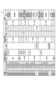
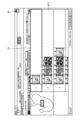
- FIG. 6 is a diagram showing an example of the contents of each of a plurality of image files.
- FIG. 7 is a diagram showing an example of body part information included in the examination result information.
- FIG. 1 is a diagram showing the overall configuration of a medical support system according to an embodiment.
- FIG. 2 is a block diagram showing the functional configuration of the main parts of the endoscope and the control device according to the embodiment.
- FIG. 3 is a block diagram showing a functional configuration
- FIG. 8 is a diagram showing an example of lesion size information regarding characteristic regions included in the examination result information.
- FIG. 9 is a diagram showing an example of treatment information included in the examination result information.
- FIG. 10 is a diagram for explaining an outline of a determination method performed by a determination unit included in a medical support device according to an embodiment.
- FIG. 11 is a diagram for explaining an outline of a determination method performed by a determination unit included in a medical support device according to an embodiment.
- FIG. 12 is a diagram for explaining an outline of a determination method performed by a determining unit included in a medical support device according to an embodiment.
- FIG. 13 is a diagram for explaining an outline of a determination method performed by a determining unit included in a medical support device according to an embodiment.
- FIG. 10 is a diagram for explaining an outline of a determination method performed by a determination unit included in a medical support device according to an embodiment.
- FIG. 11 is a diagram for explaining an outline of a determination method performed by a determination unit included
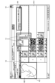
- FIG. 14 is a diagram showing an example of an imaging/report screen that is displayed on the display unit 62 by the display control unit included in the medical support device according to one embodiment.
- FIG. 15 is a flow chart showing an outline of the editing process of FIG.
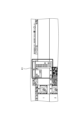
- FIG. 16 is a diagram showing an example of an imaging/report screen displayed on a display unit included in a medical support device according to an embodiment.
- FIG. 17 is a diagram that illustrates a part of a main portion of an imaging/report screen displayed on a display unit included in a medical support device according to one embodiment.
- FIG. 18 is a diagram showing a schematic view of a main part of an imaging/report screen displayed on a display unit included in a medical support device according to one embodiment.
- FIG. 19 is a diagram illustrating the edited content by the editing unit included in the medical support device according to one embodiment.
- FIG. 20 is a diagram showing another example of the imaging/report screen displayed on the display unit included in the medical support device according to one embodiment.
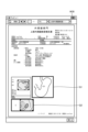
- FIG. 21 is a diagram illustrating an example of a report displayed on a display unit included in the medical support device according to an embodiment.
- FIG. 22 is a diagram illustrating an example of an image displayed on a display unit included in the medical support device according to one embodiment.
- FIG. 23 is a diagram illustrating an example of an image displayed on a display unit included in the medical support device according to one embodiment.
- FIG. 24 is a diagram illustrating an example of an image displayed on a display unit included in the medical support device according to one embodiment.
- FIG. 25 is a diagram illustrating an example of an image displayed on a display unit included in the medical support device according to one embodiment.
- FIG. 26 is a flowchart showing an outline of the transmission process of FIG.
- FIG. 1 is a diagram showing the overall configuration of a medical support system according to an embodiment of the present invention.
- the medical support system 1 shown in Fig. 1 continuously captures images of the inside of a subject, such as a human or animal, by inserting an insertion section 21 of an endoscope 2 from the mouth to the esophagus or from the anus to the large intestine of the subject, and displays a group of captured image data on a display device 3 in chronological order.
- the medical support system 1 detects (recognizes or estimates) characteristic areas including organs, parts, polyps or cancers at multiple observation sites shown in the image data and treatments on the living body using treatment tools such as forceps and snares, based on the image data group input to the image diagnostic device 5 (CAD: Computer Aided Detection) from the control device 4 and an inference model (trained model) trained using training data of images of the subject's organs, parts, lesions, etc., and outputs this detection result information to the control device 4.
- CAD Computer Aided Detection
- a surgeon such as a doctor observes and treats the subject while checking the display image displayed on the display device 3 and the detection results (estimated results) of the image diagnostic device 5.
- the medical support system 1 also acquires image files in which the medical support device 6 stores images (still image data) input from the control device 4 via the network N100, and detection result information including the detection results (estimated results) of the image diagnostic device 5, and records the acquired image files and detection result information in association with each other.
- the medical support system 1 then outputs various data in response to requests from the laptop computer 7 of the surgeon, etc., via the network N100.
- report information such as a test report of the subject by the surgeon or the like is created on the medical support device 6 or laptop computer 7, and this report information is output to the medical support device 6 and recorded.
- the surgeon diagnoses the subject and conducts a conference, etc. based on the report information and the diagnostic results of the living cells obtained by biopsy during observation of the subject.
- the medical support devices 6 send image files or reports to an image management server 8 (PACS server), and the image management server 8 manages the image files or reports sent from each medical support device 6.
- PPS server image management server
- the medical support system 1 includes an endoscope 2, a display device 3, a control device 4, an image diagnostic device 5, and a medical support device 6.
- the endoscope 2 continuously generates image data (RAW data) by capturing images of the inside of the subject, and sequentially outputs this image data to the control device 4.
- the endoscope 2 includes an insertion section 21, an operation section 22, and a universal cord 23.
- the insertion section 21 is at least partially flexible and is inserted into the subject. As shown in FIG. 1, the insertion section 21 includes a tip section 24 provided at the tip of the insertion section 21, a bending section 25 connected to the base end side (operation section 22 side) of the tip section 24 and configured to be bendable, and a long flexible tube section 26 connected to the base end side of the bending section 25 and having flexibility.
- the operation unit 22 is connected to the base end portion of the insertion unit 21.
- the operation unit 22 receives various operations on the endoscope 2. As shown in FIG. 1, the operation unit 22 is provided with a curved knob 221, an insertion port 222, and a number of operation members 223.
- the bending knob 221 is configured to be rotatable in response to a user operation by a user such as a surgeon. By rotating, the bending knob 221 operates a bending mechanism (not shown) such as a metal or resin wire arranged inside the insertion section 21. As a result, the bending section 25 is bent.
- the insertion port 222 is connected to a treatment tool channel (not shown), which is a duct extending from the tip of the insertion section 21, and is an insertion port for inserting a treatment tool or the like into the treatment tool channel from outside the endoscope 2.
- the multiple operating members 223 are composed of buttons and the like that accept various operations by users such as surgeons, and output operation signals corresponding to the various operations to the control device 4 via the universal cord 23.
- Examples of the various operations include a release operation that instructs the endoscope 2 to capture a still image, and an operation that switches the observation mode of the endoscope 2 to a normal light observation mode or a special observation mode.
- the universal cord 23 extends from the operation section 22 in a direction different from the direction in which the insertion section 21 extends, and is a cord on which a light guide 231 (see FIG. 2) made of optical fiber or the like, a first signal line 232 (see FIG. 2) for transmitting the image data described above, and a second signal line 233 (see FIG. 2) for transmitting the operation signal described above, etc. are arranged.
- a first connector section 27 is provided at the base end of the universal cord 23.
- the first connector section 27 is detachably connected to the control device 4.
- the display device 3 is composed of a display monitor such as a liquid crystal or organic EL (Electro Luminescence) display monitor, and under the control of the control device 4, displays an image based on image data that has been image-processed by the control device 4, as well as various information related to the endoscope 2.
- a display monitor such as a liquid crystal or organic EL (Electro Luminescence) display monitor
- the control device 4 is realized using a processor, which is a processing device having hardware such as a GPU (Graphics Processing Unit), FPGA (Field Programmable Gate Array), or CPU (Central Processing Unit), and a memory, which is a temporary storage area used by the processor.
- the control device 4 comprehensively controls the operation of each part of the endoscope 2 according to the program recorded in the memory.
- the image diagnostic device 5 uses a group of image data input from the control device 4 and a trained model previously trained with training data to detect (estimate) organs, parts, and the insertion speed of the insertion part 21 that appear in the image data, characteristic areas (abnormal areas or lesion candidate areas) including polyps or cancer, and treatment of the living body using treatment tools such as forceps and snares, and outputs detection result information that associates this detection result with the detection time to the control device 4.
- the image diagnostic device 5 is realized using a processor, which is a processing device having hardware such as a GPU, FPGA, or CPU, and a memory that is a temporary storage area used by the processor.
- the medical support device 6 sequentially records various data input from the control device 4 and the recognition results of the image diagnostic device 5, and transmits data in response to a request from the laptop computer 7.
- the medical support device 6 is realized using a processor, which is a processing device having hardware such as a GPU, FPGA, or CPU, and a memory, which is a temporary storage area used by the processor. Furthermore, the medical support device 6 is configured using a HDD (Hard Disk Drive), SSD (Solid State Drive), etc.
- FIG. 2 is a block diagram showing the functional configuration of the main parts of the endoscope 2 and the control device 4.
- the endoscope 2 and the control device 4 will be described in that order, and then the image diagnostic device 5 and the medical support device 6 will be described.
- the endoscope 2 includes an illumination optical system 201, an imaging optical system 202, an imaging element 203, an A/D conversion unit 204, a P/S conversion unit 205, an imaging recording unit 206, and an imaging control unit 207.
- each of the illumination optical system 201, the imaging optical system 202, the imaging element 203, the A/D conversion unit 204, the P/S conversion unit 205, the imaging recording unit 206, and the imaging control unit 207 is disposed within the tip portion 24.
- the illumination optical system 201 is composed of one or more lenses, and irradiates the illumination light supplied from the light guide 231 toward the subject.
- the imaging optical system 202 is composed of a plurality of lenses and an actuator consisting of a stepping motor or a voice coil motor that moves a predetermined lens among the plurality of lenses in the optical axis direction.
- the imaging optical system 202 focuses light reflected from the subject, light returned from the subject, fluorescent light emitted by the subject, and the like, to form an image of the subject on the light receiving surface of the image sensor 203.
- the imaging optical system 202 can change the focal length (imaging magnification or enlargement magnification) and the focal position by moving a predetermined lens along the optical axis direction O1 under the control of the imaging control unit 207.
- the imaging optical system 202 can change the imaging magnification to 1x, 80x, or 520x.
- the imaging optical system 202 does not need to change the imaging magnification stepwise, and may be one that can change the imaging magnification linearly.
- the image sensor 203 is configured using a CCD (Charge Coupled Device) or CMOS (Complementary Metal Oxide Semiconductor) image sensor in which one of the color filters constituting a Bayer array (RGGB) is arranged on each of a plurality of pixels arranged in a two-dimensional matrix.
- the image sensor 203 receives the subject image formed by the imaging optical system 202 under the control of the imaging control unit 207, and performs photoelectric conversion to generate an image (analog signal).
- the image sensor 203 may be configured integrally with an image sensor and a TOF (Time Of Flight) sensor that acquires subject distance information (hereinafter referred to as depth map information) using a TOF method.
- TOF Time Of Flight
- the depth map information is information that detects the subject distance from the position of the image sensor 203 (the position of the tip 24) to the corresponding position on the observation target corresponding to the pixel position in the captured image for each pixel position.
- the configuration for generating the depth map information is not limited to the above-mentioned TOF sensor, and an image sensor including a phase difference sensor may also be used.
- the depth map information and the captured image will be collectively referred to as image data.
- the image sensor 203 outputs the image data to the A/D conversion unit 204.
- the A/D conversion unit 204 is configured using an A/D conversion circuit, etc. Under the control of the imaging control unit 207, the A/D conversion unit 204 performs A/D conversion processing on the analog image data input from the imaging element 203, and outputs the result to the P/S conversion unit 205.
- the P/S conversion unit 205 is constructed using a P/S conversion circuit, etc., and under the control of the imaging control unit 207, performs parallel/serial conversion on the digital image data input from the A/D conversion unit 204, and outputs it to the control device 4 via the first signal line 232.
- an E/O conversion unit that converts image data into an optical signal may be provided, and the image data may be output to the control device 4 by the optical signal.
- the image data may be transmitted to the control device 4 by wireless communication such as Wi-Fi (Wireless Fidelity) (registered trademark).
- the imaging and recording unit 206 is composed of a non-volatile memory or a volatile memory, and records various information related to the endoscope 2 (for example, pixel information of the imaging element 203).
- the imaging and recording unit 206 also records various setting data and control parameters transmitted from the control device 4 via the second signal line 233.
- the imaging control unit 207 is realized using a TG (Timing Generator), a processor which is a processing device having hardware such as a CPU, and a memory which is a temporary storage area used by the processor.
- the imaging control unit 207 controls the operation of each of the imaging element 203, the A/D conversion unit 204, and the P/S conversion unit 205 based on the setting data received from the control device 4 via the second signal line 233.
- the control device 4 includes a focusing lens 401, a first light source unit 402, a second light source unit 403, a light source control unit 404, an S/P conversion unit 405, an image processing unit 406, an input unit 407, a recording unit 408, a communication unit 409, and a control unit 410.
- the condenser lens 401 condenses the light emitted by each of the first light source unit 402 and the second light source unit 403, and emits the light to the light guide 231.
- the first light source unit 402 emits visible white light (normal light) under the control of the light source control unit 404, and supplies the white light as illumination light to the light guide 231.
- This first light source unit 402 is configured using a collimator lens, a white LED (Light Emitting Diode) lamp, a driving driver, and the like.
- the first light source unit 402 may be configured using a red LED lamp, a green LED lamp, and a blue LED lamp that emit light simultaneously to supply visible white light.
- the first light source unit 402 may also be configured using a halogen lamp, a xenon lamp, and the like.
- the special light is light used for narrow band imaging (NBI) using narrow band light including 390 to 445 nm and 530 to 550 nm.
- the special light may be amber light (600 nm and 630 nm) used for red dichromatic imaging (RDI) other than narrow band light.
- the light source control unit 404 is realized using a processor having hardware such as an FPGA or a CPU, and a memory that is a temporary storage area used by the processor.
- the light source control unit 404 controls the light emission timing and light emission time of each of the first light source unit 402 and the second light source unit 403 based on control data input from the control unit 410.
- the S/P conversion unit 405 Under the control of the control unit 410, the S/P conversion unit 405 performs serial/parallel conversion on the image data received from the endoscope 2 via the first signal line 232, and outputs the data to the image processing unit 406. If the endoscope 2 outputs image data as an optical signal, an O/E conversion unit that converts an optical signal into an electrical signal may be provided instead of the S/P conversion unit 405. Also, if the endoscope 2 transmits image data via wireless communication, a communication module capable of receiving wireless signals may be provided instead of the S/P conversion unit 405.
- the image processing unit 406 is realized by using a processor having hardware such as a GPU or FPGA, and a memory that is a temporary storage area used by the processor. Under the control of the control unit 410, the image processing unit 406 performs a predetermined image processing on the image data of the parallel data input from the S/P conversion unit 405, and outputs the result to the display device 3. Examples of the predetermined image processing include demosaic processing, white balance processing, gain adjustment processing, gamma correction processing, and format conversion processing.
- the input unit 407 is configured using a mouse, foot switch, keyboard, buttons, switches, a touch panel, etc., and accepts user operations by a user such as a surgeon, and outputs an operation signal corresponding to the user operation to the control unit 410.
- the recording unit 408 is configured using a recording medium such as a volatile memory, a non-volatile memory, an SSD (Solid State Drive), an HDD (Hard Disk Drive), a memory card, etc.
- the recording unit 408 records data including various parameters necessary for the operation of the control device 4 and the endoscope 2.
- the recording unit 408 also has a program recording unit 408a that records various programs for operating the endoscope 2 and the control device 4, an image data recording unit 408b that records an image file that stores an image corresponding to the image data, and an inspection result information recording unit 408c that records detection result information.
- the image data recording unit 408b records the image data group generated by the endoscope 2 successively capturing images of multiple observation sites on the subject and the images corresponding to the still image data (endoscopic images) in association with patient information, etc.
- the still image data is image data captured by the image sensor 203 when imaging is instructed by a release signal input from the operation unit 22, and is image data with a higher resolution than the live view images sequentially generated by the image sensor 203.
- the examination result information recording unit 408c records the detection result information input from the imaging diagnostic device 5, the detection time of this detection result, and patient information in association with each other.
- the detection result information includes the type of characteristic region, size information indicating the size of the characteristic region (lesion size information), site information regarding the organ or site inside the subject's body at the time the image was captured, and treatment information regarding treatment using a treatment tool.
- the characteristic region is a lesion region including cancer, lesions, bleeding, etc. detected by the imaging diagnostic device 5, which will be described later.
- the communication unit 409 under the control of the control unit 410, transmits various information to the image diagnostic device 5 and the medical support device 6 via the network N100, and receives various information from the image diagnostic device 5 and the medical support device 6 and outputs it to the control unit 410. Specifically, under the control of the control unit 410, the communication unit 409 transmits a group of temporally continuous image data that has been subjected to image processing by the image processing unit 406 to the image diagnostic device 5, receives detection results including organs, parts, and characteristic areas detected in the image diagnostic device 5, and outputs them to the control unit 410.
- the communication unit 41 transmits detection result information including image data groups (moving image data), image data (still image data), and detection results of the image diagnostic device 5 to the medical support device 6, and receives patient information of the subject, observation information indicating the observation order of the observation points during the examination of the subject, and the like from the medical support device 6.
- the communication unit 409 is configured using a communication module, etc.
- the control unit 410 corresponds to the second processor of the present disclosure.
- This control unit 410 is realized using a second processor, which is a processing device having hardware such as an FPGA or a CPU, and a memory, which is a temporary storage area used by the second processor.
- the control unit 410 comprehensively controls each unit constituting the endoscope 2 and the control device 4.
- the control unit 410 has an imaging control unit 410a and an acquisition unit 410b.
- the imaging control unit 410a controls the imaging of the endoscope 2.
- the imaging control unit 410a generates a group of image data that is continuous in time by having the endoscope 2 capture images continuously. Furthermore, when a release signal is input from the operation unit 22, the imaging control unit 410a causes the image sensor 203 to capture still image data.
- the acquisition unit 410b acquires image data from the endoscope 2 via the S/P conversion unit 405 or image processing unit 406, and records the data in the image data recording unit 408b.
- the acquisition unit 410b also acquires detection result information from the image diagnostic device 5 via the communication unit 409, and records the information in the examination result information recording unit 408c.
- Fig. 3 is a block diagram showing the functional configuration of the imaging diagnostic device 5.
- the imaging diagnostic device 5 shown in Fig. 3 includes a communication unit 51, an input unit 52, a recording unit 53, a display unit 54, and a control unit 55.
- the communication unit 51 Under the control of the control unit 55, the communication unit 51 receives from the control device 4 via the network N100 a group of image data generated by the endoscope 2 and organ/part order information indicating the observation order of the organs/parts in the subject, i.e. the patient, and outputs these to the control unit 55. Also, under the control of the control unit 55, the communication unit 51 outputs to the control device 4 via the network N100 detection result information including the detection result of the subject's organs, etc., input from the control unit 55, and the detection time when this detection result was detected.
- the communication unit 51 is configured using a communication module, etc.
- the input unit 52 is configured using buttons, switches, a touch panel, etc., and accepts various inputs and outputs them to the control unit 55.
- the recording unit 53 is configured using a recording medium such as a volatile memory, a non-volatile memory, an SSD, an HDD, a memory card, etc.
- the recording unit 53 records data including various parameters etc. required for the operation of the image diagnostic device 5.
- the recording unit 53 also has a program recording unit 531 that records various programs for operating the image diagnostic device 5, an observation order recording unit 532, an inference model recording unit 533, and a detection result information recording unit 534.
- the observation order recording unit 532 records the observation order information input from the medical support device 6, which sets the observation order of multiple observation locations such as organs and parts that are set in advance, when observing a subject with the endoscope 2.
- the inference model recording unit 533 records an inference model used to detect organs, parts, and characteristic regions based on image data.
- the inference model takes image data of the endoscope 2 as input, and outputs the organs, parts, and characteristic regions contained in the image data.
- This inference model is a model generated by machine learning using artificial intelligence (AI (Artificial Intelligence)), for example.
- AI Artificial Intelligence
- the inference model is a model such as deep learning that learns using teacher data in which image data of a subject is given the subject's organs, parts, and characteristic regions such as lesions, treatment tools, and treatments, and outputs the organs, parts, characteristic regions, and the sizes of the characteristic regions, treatment tools, and treatment contents contained in the image data.
- the detection result information recording unit 534 records the detection result information detected by the imaging diagnostic device 5, the detection time of this detection result, and patient information in association with each other.
- the display unit 54 displays various information related to the imaging diagnostic device 5 under the control of the control unit 55.
- the display unit 54 is configured using a liquid crystal display, an organic EL display, etc.
- the control unit 55 is realized using a processor having hardware such as an FPGA or a CPU, and a memory that is a temporary storage area used by the processor.
- the control unit 55 comprehensively controls each unit that constitutes the medical support device 6.
- the control unit 55 has an acquisition unit 551, an organ/part detection unit 552, and a detection time acquisition unit 553.
- the acquisition unit 551 acquires image data generated sequentially by the endoscope 2 from the control device 4 via the communication unit 51 in chronological order.
- the organ/part detection unit 552 detects the organs/parts of the subject contained in the image data based on the image data sequentially acquired by the acquisition unit 551 and the inference model recorded by the inference model recording unit 533, and records this detection result in the detection result information recording unit 534 as test result information.
- the detection time acquisition unit 553 acquires the detection time when the organ/part detection unit 552, the characteristic area detection unit 554 described below, and the treatment detection unit 555 detect the subject's organ/part, characteristic area, and treatment contained in the image data. For example, the detection time acquisition unit 553 acquires as the detection time the time measured by a TG (not shown) when the organ/part detection unit 552 detects the subject's organ/part contained in the image data.
- the characteristic region detection unit 554 detects the characteristic regions and the sizes of the characteristic regions contained in the image data based on the image data sequentially acquired by the acquisition unit 551 and the inference model recorded by the inference model recording unit 533, and records the detection results as examination result information in the detection result information recording unit 534.
- the characteristic regions are lesions such as cancer, bleeding, polyps, etc.
- the treatment detection unit 555 detects the type of treatment tool contained in the image data and the treatment performed on the living body by the treatment tool as treatment information based on the image data sequentially acquired by the acquisition unit 551 and the inference model recorded by the inference model recording unit 533, and records this detection result as examination result information in the detection result information recording unit 534.
- treatment on the living body includes obtaining a living body by biopsy, resection of a living body, thermal treatment of a living body, etc., and also includes medical procedures such as injection of saline solution into a living body.
- Fig. 4 is a block diagram showing the functional configuration of the medical support device 6.
- the medical support device 6 shown in Fig. 4 includes a communication unit 61, a display unit 62, an input unit 63, a database 64 (hereinafter simply referred to as "DB 64"), a program recording unit 65, and a control unit 66.
- DB 64 database 64
- the communication unit 61 transmits various information to the control device 4 and the image diagnostic device 5 via the network N100, and receives various information from the control device 4 and the image diagnostic device 5.
- the communication unit 61 is configured using a communication module.
- the display unit 62 displays various information related to the medical support device 6 under the control of the control unit 66.
- the display unit 62 is configured using a liquid crystal display, an organic EL display, etc.
- the input unit 63 accepts various inputs in response to external operations and outputs them to the control unit 66.
- the input unit 63 is configured using buttons, a keyboard, switches, a touch panel, etc.
- DB64 records various information.
- DB64 is configured using a HDD, SSD, etc.
- DB64 has a patient information DB641, an endoscope DB642, an image data DB643, an examination result information DB644, an observation order information DB645, a report information DB646, an operator information DB647, and a transmission setting information DB648.
- Patient information DB641 records, for each patient, a patient ID that identifies the patient, the patient's date of birth, the patient's doctor, the patient's address, and the patient's allergy information.
- the endoscope DB 642 records, for each endoscope 2, the type of endoscope 2, the endoscope ID, the repair history of the endoscope 2, the maintenance status of the endoscope 2, cleaning history information relating to the cleaning history of the endoscope 2, the usage history and planned usage information of the endoscope 2.
- the image data DB 643 records a group of image data captured by the endoscope 2 in association with each patient ID or each surgeon ID.
- the examination result information DB 644 records past examination results for each patient ID. Furthermore, the examination result information DB 644 records detection result information in which the image diagnostic device 5 detects multiple organs, parts, characteristic areas, and treatment information in the subject based on the image data group captured by the endoscope 2, in association with the examination results for each patient ID.
- the observation order information DB 645 records the observation order of organs and parts using the endoscope 2, which is set for each facility or surgeon ID.
- the report information DB 646 records, for each patient ID or each surgeon ID, the report information generated by the endoscope 2 by the surgeon (radiography reader) and the report information automatically generated by the medical support device 6 in association with each other.
- the surgeon information DB 647 records the name, position, affiliation, and contact information for each surgeon ID.
- the transmission setting information DB 648 records various setting information previously set by the user when the medical support device 6 transmits images to the image management server 8. Specifically, the transmission setting information DB 648 records setting information for transmitting only a specific image, for example a representative image, from among multiple images when the medical support device 6 transmits images to the image management server 8.
- the program recording unit 65 is configured using volatile memory, non-volatile memory, SSD, etc., and records various programs for operating the medical support device 6.
- the control unit 66 corresponds to the first processor of the present disclosure.
- This control unit 66 is realized using a first processor having hardware such as an FPGA or a CPU, and a memory that is a temporary storage area used by the first processor.
- the control unit 66 comprehensively controls each unit that constitutes the medical support device 6.
- the control unit 66 has an acquisition unit 661, a determination unit 662, a creation unit 663, a selection unit 664, a display control unit 665, an editing unit 666, a generation unit 667, and a transmission control unit 668.
- the acquisition unit 661 acquires multiple image files from the control device 4 and test result information from the image diagnostic device 5 via the network N100.
- the acquisition unit 661 records the multiple image files in the image data DB 643 and in the test result information DB 644.
- the determination unit 662 determines whether the same characteristic area is included in each of the multiple images based on the imaging magnification information and the detection result information included in the multiple image files acquired by the acquisition unit 661. Specifically, the determination unit 662 classifies the multiple images into the same group by determining whether the multiple images include the same characteristic area (same lesion). More specifically, the determination unit 662 determines whether the multiple images include the same characteristic area (same lesion) by determining whether the multiple images include the same characteristic area (same lesion).
- the determination unit 662 determines whether the multiple enlarged images (imaging magnification of 2 or more) within the period between the time of the image with the imaging magnification of 1 indicating a non-magnified image as the starting point and the time of the image with the imaging magnification of 1 indicating a non-magnified image as the ending point are images with the same characteristic area.
- the determination unit 662 also determines whether the group of images including the same lesion are the same characteristic area, i.e., the same lesion images, based on the imaging time, the site information, and the lesion size.
- the determination unit 662 determines that images that are consecutive in time and have a magnification of 1, are captured within a predetermined time (e.g., within one minute), and have the same site and pathogen size, are the same characteristic region, that is, the same lesion images captured of different lesions.
- a predetermined time e.g., within one minute
- the determination unit 662 determines that the images are the same characteristic region, that is, the same lesion images captured of different lesions.
- the creation unit 663 creates an image group for each characteristic region based on the determination result made by the determination unit 662. Specifically, the creation unit 663 creates an image group for each different lesion based on the determination result made by the determination unit 662.
- the selection unit 664 selects a representative image for each group created by the creation unit 663 based on the imaging magnification information. Specifically, when a group contains multiple images with the same imaging magnification, the selection unit 664 selects, for example, the image captured at the earliest time as the representative image. Furthermore, when the same group contains multiple images with different imaging magnifications, the selection unit 664 selects a representative image for each imaging magnification.
- the display control unit 665 displays an imaging/report screen including the representative image for each group selected by the selection unit 664 on the display unit 62.
- the editing unit 666 displays and edits according to the operation contents of the user on the input unit 63. Specifically, the editing unit 666 performs editing according to the operation contents of the user on the input unit 63, for example, by linking the group number to a predetermined portion in a schema diagram described later in a group number field.
- the generation unit 667 generates a report according to the operation contents of the input unit 63 by the user. Specifically, the generation unit 667 accepts input of disposition information regarding the diagnosis contents of the user's subject according to the operation contents of the user, registers the accepted diagnosis information, and then generates a report that reflects the diagnosis information.
- the transmission control unit 668 deletes all images except the representative image of the group from the image data DB 643, and transmits only the representative image of each group to the image management server 8.
- the transmission control unit 668 also transmits all images, including the representative image of each group and the still image group, to the image management server 8.
- the acquisition unit 661 acquires multiple image files from the control device 4 and test result information from the image diagnostic device 5 (step S101).
- FIG. 6 is a diagram showing an example of the contents of each of a plurality of image files.
- FIG. 7 is a diagram showing an example of site information included in the test result information.
- FIG. 8 is a diagram showing an example of lesion size information related to characteristic regions included in the test result information.
- FIG. 9 is a diagram showing an example of treatment information included in the test result information.
- an image (still image data), a time stamp indicating the time of image capture by the endoscope 2, and a magnification indicating the image capture magnification information of the endoscope 2 are recorded in association with each other.
- a time stamp of "0:05:00” and a magnification of "x1" are recorded in association with the image "Image P1".
- the image is still image data such as JPEG data or RAW data captured by the endoscope 2.
- a magnification of "x1" indicates a non-magnified image.
- a StartTime indicating the detection start time and an EndTime indicating the detection end time are recorded in association with each organ or part. Specifically, a StartTime of "0:05:00" and an EndTime of "0:05:59" are recorded in association with the part "ileum.”
- a StartTime indicating the detection start time and an EndTime indicating the detection end time are recorded in association with each lesion size indicating the feature area size in the feature area (hereinafter simply referred to as "lesion size"). Specifically, a lesion size of "5 mm” is recorded in association with a StartTime of "0:05:00” and an EndTime of "0:05:10".
- a StartTime indicating the detection start time and an EndTime indicating the detection end time are recorded in association with each treatment. Specifically, a StartTime of "0:10:30" and an EndTime of "0:10:35" are recorded in association with the treatment "biopsy.”
- step S102 the determination unit 662 determines whether the same feature regions included in each of the multiple images belong to the same group based on the imaging magnification information and detection result information included in the multiple image files acquired by the acquisition unit 661 (step S102).
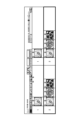
- FIG. 10 is a diagram for explaining an overview of the determination method used by the determination unit 662.
- FIG. 11 is a diagram for explaining an overview of the determination method used by the determination unit 662.
- FIG. 12 is a diagram for explaining an overview of the determination method used by the determination unit 662.
- FIG. 13 is a diagram for explaining an overview of the determination method used by the determination unit 662. Note that the image numbers in FIGS. 10 to 13 are merely examples, and the imaging magnification, the subject's organs, parts, and treatment contents may differ between the figures.
- the determination unit 662 generates an integrated information table T5 that integrates the imaging magnification information, the site information, the lesion size information, and the treatment information contained in the detection result information, which are contained in the multiple image files acquired by the acquisition unit 661, based on the detection time of each information. Specifically, as shown in Fig. 10, the determination unit 662 generates the integrated information table T5 by arranging and integrating the information in order from earliest to latest time stamp, and by recording (storing) the detection result information of the same time in association with the rows of images of the same time.
- the determination unit 662 determines whether images have the same characteristic area (area of the same lesion) in the same group using one or more of the following determination methods 1 to 3. Specifically, the determination unit 662 classifies each of the multiple images into the same group having the same characteristic area (the same lesion) by determining whether the images contain the same characteristic area (the same lesion).
- the determination unit 662 first determines, among the images P1 to P16, the time of an image with a magnification of 1 (x1) indicating a non-magnified image as the starting point, and the time of an image with a magnification of 1 (x1) indicating a non-magnified image as the ending point, and determines a plurality of enlarged images (with an imaging magnification of 2 or more) within the period between them as images having the same characteristic region. That is, the determination unit 662 determines, based on the imaging magnification information, a group of images including the same lesion as images of the same lesion.
- the determination unit 662 determines that images P1 to P7, which are multiple enlarged images during the period between the time (0:05:00) of image P1 with a magnification of 1 ( ⁇ 1) indicating a non-magnified image and the time (0:0:7:40) of image P9 with a magnification of 1 ( ⁇ 1) indicating a non-magnified image, have the same characteristic region.
- the determination unit 662 determines that images P1 to P7 are images of the same lesion.
- the determination unit 662 determines that images P11 to P13, images P14 to P17, and images P19 to P23 are images of different characteristic regions, that is, images of the same lesion for different lesions in the subject.
- the determination unit 662 determines that images P1 to P8, images P9 to P12, and images P14 to P16 are images having the same characteristic area, that is, images of the same lesion for different lesions in the subject.
- the determination unit 662 determines, based on the imaging time, the body part information, and the lesion size, that a group of images including the same lesion are the same feature region, i.e., the same lesion images.
- the determination unit 662 determines that image P10 and image P11 are images with the same characteristic region if they are non-magnified images with a magnification of 1 (x1) that are consecutive in time, were captured within a predetermined time period (e.g., within one minute), and have the same imaged site (ascending colon) and pathogen size (5 mm). In other words, the determination unit 662 determines that image P10 and image P11 are images of the same lesion captured from different lesions.
- the determination unit 662 determines that image P1 and image P2, which have the same imaging site (ascending colon) and pathogen size (5 mm), are images with the same feature area, i.e., they are images of the same lesion captured of different lesions.
- determination method 3 Next, a description will be given of determination method 3. As shown in Fig. 11 to Fig. 13, in the case of an image with the maximum imaging magnification followed by a non-magnified image with a magnification of 1, if the imaging times are within a certain period of time, the site is the same, and a treatment is being performed during that time, the determination unit 662 determines that these images are images of the same characteristic region.
- the determination unit 662 determines that image P17 and image P18 are images of the same characteristic region. In other words, the determination unit 662 determines that image P17 and image P18 are the same lesion images captured of the same lesion (characteristic region).
- the determination unit 662 determines that image P12 and image P13, in which a biological procedure has been performed, are images of the same characteristic region, i.e., they are the same lesion images captured of the same lesion (characteristic region).
- the determination unit 662 uses one or more of determination methods 1 to 3 to classify the images contained in each of the multiple image files into images of the same characteristic area, i.e., images of the same lesion for each different lesion, to make a determination.
- step S104 the creation unit 663 creates an image group for each characteristic region based on the determination result made by the determination unit 662. Specifically, in the case of the above-mentioned Fig. 12 and Fig. 13, the creation unit 663 creates, for images P1 to P16, group G1 for images P1 to P8, group G3 for images P9 to P13, and group G4 for images P14 to P16, based on the determination result made by the determination unit 662.
- the selection unit 664 selects a representative image for each group created by the creation unit 663 based on the imaging magnification information (step S104). Specifically, when images with the same imaging magnification are included in each group created by the creation unit 663, the selection unit 664 selects the image with the earliest imaging time as the representative image. Specifically, as shown in FIG. 12 and FIG. 13, in the case of group G1 created by the creation unit 663, when images with the same imaging magnification are included, the selection unit 664 selects image P1 with the earliest imaging time as the representative image of the non-magnified image, and selects image P4 with the earliest imaging time as the representative image with an imaging magnification of 520 times ( ⁇ 520).
- the selection unit 664 may select the image with the latest imaging time or the image located at the intermediate time of the same magnification as the representative image, and when there are multiple images with the same magnification, the selection unit 664 may select the representative image according to the settings set in advance by the surgeon in the medical support device 6, or may select the image with the best focus as the representative image.
- the display control unit 665 displays an imaging/report screen including the representative image for each group selected by the selection unit 664 on the display unit 62 (step S105).
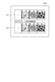
- FIG. 14 is a diagram showing an example of the imaging and report screen that the display control unit 665 causes the display unit 62 to display.
- the imaging and report screen W1 includes a schematic diagram W11 that simulates the internal organs or parts of the subject's body, and a display area W12 in which representative images for each group determined to have the same characteristic area are displayed.
- the display control unit 665 displays a representative image for each group in the display area W12. Furthermore, the display control unit 665 displays each group in association with a number and the position in the organ in the subject's body where the image was taken. Specifically, the display control unit 665 displays the group imaged at the position numbered "1" in the schematic drawing W11 as group G1, the group imaged at the position numbered "2" in the schematic drawing W11 as group G2, and the group imaged at the position numbered "3" in the schematic drawing W11 as group G3. Furthermore, the display control unit 665 displays an icon A1, which indicates that there are multiple images imaged at the same imaging magnification other than the representative image, superimposed on the representative image.
- step S106 the determination unit 662 determines whether or not the user has operated the input unit 63. If the determination unit 662 determines that the user has operated the input unit 63 (step S106: Yes), the medical support device 6 proceeds to step S107, which will be described later. On the other hand, if the determination unit 662 determines that the user has not operated the input unit 63 (step S106: No), the medical support device 6 proceeds to step S112, which will be described later.
- step S107 the determination unit 662 determines whether the user's operation on the input unit 63 is an editing operation. If the determination unit 662 determines that the user's operation on the input unit 63 is an editing operation (step S107: Yes), the medical support device 6 proceeds to step S108, which will be described later. On the other hand, if the determination unit 662 determines that the user's operation on the input unit 63 is not an editing operation (step S107: No), the medical support device 6 proceeds to step S110, which will be described later.
- step S108 the medical support device 6 executes an editing process, such as associating the images of each group with a schematic diagram showing an organ in a simulated manner and inputting findings, based on the user's operation on the input unit 63. Details of the editing process will be described later. After step S108, the medical support device 6 proceeds to step S109, which will be described later.
- step S109 the determination unit 662 determines whether or not the user has performed an end operation on the input unit 63. If the determination unit 662 determines that the user has performed an end operation on the input unit 63 (step S109: Yes), the medical support device 6 ends this process. On the other hand, if the determination unit 662 determines that the user has not performed an end operation on the input unit 63 (step S109: No), the medical support device 6 returns to the above-mentioned step S105.
- step S110 the determination unit 662 determines whether or not the user has performed a sending operation on the input unit 63 to send an image to the image management server 8. If the determination unit 662 determines that the user has performed a sending operation on the input unit 63 to send an image to the image management server 8 (step S110: Yes), the medical support device 6 proceeds to step S111, which will be described later. On the other hand, if the determination unit 662 determines that the user has not performed a sending operation on the input unit 63 to send an image to the image management server 8 (step S110: No), the medical support device 6 proceeds to step S109.
- step S111 the medical support device 6 executes a transmission process to transmit an image corresponding to the user's operation on the input unit 63 to the image management server 8. Details of the transmission process will be described later. After step S111, the medical support device 6 proceeds to step S109.
- step S112 the determination unit 662 determines whether a predetermined time has elapsed, for example, five minutes, since the multiple images were displayed as a group. If the determination unit 662 determines that the predetermined time has elapsed since the multiple images were displayed as a group (step S112: Yes), the medical support device 6 ends this process. On the other hand, if the determination unit 662 determines that the predetermined time has not elapsed since the multiple images were displayed as a group (step S112: No), the medical support device 6 returns to the above-mentioned step S105.
- a predetermined time for example, five minutes
- Fig. 15 is a flow chart showing an outline of the editing process.
- the determination unit 662 determines whether the editing operation is an organ/part editing operation that links an image to an organ/part (step S201).
- the imaging/report screen W1 includes a cell K1 that accepts input of an instruction signal to display an image corresponding to a selected desired organ or part, a button K2 that accepts input of an instruction signal to add a group number to the report, a cell K3 that accepts input of an instruction signal to search for and display a group number, and a cell area K4 that accepts input of an instruction signal to display a past group image of the same subject.
- the determination unit 662 determines whether or not the user has selected a desired organ or part from the cell K1 in the imaging/report screen W1 displayed by the display unit 62 by operating the input unit 63, and if the desired organ or part is selected in the cell K1, determines that the editing operation is organ/part editing that links an image to an organ/part. If the determination unit 662 determines that the editing operation is organ/part editing that links an image to an organ/part (step S201: Yes), the medical support device 6 proceeds to step S203 described later. On the other hand, if the determination unit 662 determines that the editing operation is not an organ/part editing operation linked to an organ/part (step S201: No), the medical support device 6 proceeds to step S205, which will be described later.
- step S202 the display control unit 665 displays images for each organ/part in each group linked to the organ or part selected in cell K1, according to the user's operation on the input unit 63.
- FIG. 17 is a diagram showing a schematic representation of a portion of the imaging and report screen displayed by the display unit 62.
- FIG. 18 is a diagram showing a schematic representation of a portion of the imaging and report screen displayed by the display unit 62.
- the display control unit 665 displays organ/part names D1 to D3 for each group linked to the organ or part selected in cell K1 (FIG. 17 ⁇ FIG. 18). In this case, the display control unit 665 displays the names of each organ and part superimposed on the group number. For example, as shown in FIG. 18, the display control unit 665 displays "esophagus-neck" superimposed on group number "1". This allows the user to check an image of the desired organ or part.
- step S 203 the editing unit 666 performs display and editing in accordance with the operation content of the user on the input unit 63 .
- FIG. 19 is a diagram showing the edited content by the editing unit 666.
- the editing unit 666 performs the user's operation on the input unit 63, for example, dragging and dropping the group number G1 field, and performs editing to link the group number "G1" to a specific part in the schematic diagram W21.
- the medical support device 6 proceeds to step S204, which will be described later.
- step S204 the determination unit 662 determines whether or not the user has performed a termination operation on the input unit 63.
- the determination unit 662 determines that the user has performed a termination operation on the input unit 63 (step S204: Yes)
- the medical support device 6 returns to the main routine of Fig. 5.
- step S204: No the medical support device 6 returns to the above-mentioned step S201.
- step S205 the determination unit 662 determines whether or not the user has performed a report generation operation on the input unit 63. If the determination unit 662 determines that the user has performed a report generation operation on the input unit 63 (step S205: Yes), the medical support device 6 proceeds to step S206, which will be described later. On the other hand, if the determination unit 662 determines that the user has not performed a report generation operation on the input unit 63 (step S205: No), the medical support device 6 proceeds to step S207, which will be described later.
- step S206 the generation unit 667 generates a report according to the operation of the input unit 63 by the user.
- FIG. 20 is a diagram showing another example of an imaging/report screen displayed by the display unit 62.
- FIG. 21 is a diagram showing an example of a report displayed by the display unit 62.
- the generation unit 667 accepts input of decision information regarding the diagnosis of the subject by the user according to the operation by the user, and registers the accepted diagnosis information. Thereafter, as shown in FIG. 21, the generation unit 667 generates a report W30 that reflects the diagnosis information accepted in FIG. 20.
- the display control unit 665 displays the report W30 generated by the generation unit 667 on the display unit 62.
- the report W30 includes a schematic diagram Q1 in addition to the diagnosis information for the subject, and a representative image Q2 of the group number linked to the schematic diagram Q1. This allows the user to view the report W30 and grasp the position and image of the diagnosis site in addition to the diagnosis information diagnosed by the operator of the endoscope 2.
- the medical support device 6 proceeds to step S204.
- step S207 the determination unit 662 determines whether or not the user has performed a lesion operation on the input unit 63.
- the determination unit 662 determines that the user has performed a lesion operation on the input unit 63 (step S207: Yes)
- the medical support device 6 proceeds to step S208, which will be described later.
- step S207: No the medical support device 6 proceeds to step S209, which will be described later.
- step S209 the determination unit 662 determines whether or not the user has performed a past comparison operation on the input unit 63.
- the determination unit 662 determines that the user has performed a past comparison operation on the input unit 63 (step S209: Yes)
- the medical support device 6 proceeds to step S210, which will be described later.
- step S207: No the medical support device 6 proceeds to S204.
- the determination unit 662 determines whether or not to transmit only the representative image of each group (step S301). Specifically, the determination unit 662 determines whether or not the user has set setting information in advance in the transmission setting information DB 648 for transmitting only the representative image of each group, and if setting information for transmitting only the representative image has been set, the determination unit 662 determines that only the representative image of each group will be transmitted. If the determination unit 662 determines that only the representative image of each group will be transmitted (step S301: Yes), the medical support device 6 proceeds to step S302, which will be described later. On the other hand, if the determination unit 662 determines that only the representative image of each group will not be transmitted (step S301: No), the medical support device 6 proceeds to step S305, which will be described later.
- step S302 the determination unit 662 determines whether or not deletion is set to delete images other than the representative image of each group. Specifically, the determination unit 662 determines whether or not deletion is set in advance for deleting images other than the representative image of each group after the user transmits the representative image of each group to the transmission setting information DB 648, and if deletion is set, the determination unit 662 determines that only the representative image of each group will be transmitted. If the determination unit 662 determines that deletion is set to delete images other than the representative image of each group (step S302: Yes), the medical support device 6 proceeds to step S303, which will be described later. On the other hand, if the determination unit 662 determines that deletion is not set to delete images other than the representative image of each group (step S302: No), the medical support device 6 proceeds to step S304, which will be described later.
- step S303 the transmission control unit 668 deletes all images except the representative image of each group from DB6, and transmits only the representative image of each group to the image management server 8. This reduces the amount of data to be transmitted and increases the recording capacity of DB6.
- step S303 the medical support device 6 returns to the main routine of FIG. 5.
- step S304 the transmission control unit 668 transmits only the representative image of each group to the image management server 8. After step S304, the medical support device 6 returns to the main routine of FIG. 5.
- step S305 the transmission control unit 668 transmits all images, including the representative image and still image group of each group, to the image management server 8. After step S305, the medical support device 6 returns to the main routine of FIG. 5.
- the selection unit 664 displays on the display unit 62 an imaging/report screen including a representative image for each group selected, allowing the user to easily and efficiently review a large number of endoscopic images with different magnifications.
- the determination unit 662 determines whether a plurality of images contain the same characteristic area (same lesion), and classifies images having the same characteristic area (same lesion) into the same group, so that the user can easily and efficiently check a large number of endoscopic images with different magnifications.
- the determination unit 662 determines that among the multiple images, the time of an image with an imaging magnification of 1, which indicates a non-magnified image, is the starting point, and the time of an image with an imaging magnification of 1, which indicates a non-magnified image, is the ending point, and determines that multiple enlarged images (with imaging magnifications of 2 or more) within that period are images that have the same characteristic area, so that the user can easily and efficiently check a large number of endoscopic images with different magnifications.
- the determination unit 662 determines that images that are consecutive in time, non-magnified at a magnification of 1, captured within a predetermined time period (e.g., within one minute), and have the same captured part of the body and the same pathogen size, are images that have the same characteristic area, thereby preventing the user from viewing images in duplicate.
- a predetermined time period e.g., within one minute
- the transmission control unit 668 deletes all images other than the representative image of the group from DB64 and transmits only the representative image of each group to the image management server 8, which reduces the amount of data transmitted and increases the storage capacity of DB6.
- the transmission control unit 668 transmits only the representative image of each group to the image management server 8, thereby reducing the amount of data transmitted.
- the display control unit 665 displays images from multiple image files based on selection information that selects one of an organ, a body part, an image group, and a characteristic area, so that the image desired by the user can be displayed efficiently.
- Various inventions can be formed by appropriately combining multiple components disclosed in the medical support system according to the embodiment of the present disclosure described above. For example, some components may be deleted from all the components described in the medical support system according to the embodiment of the present disclosure described above. Furthermore, the components described in the medical support system according to the embodiment of the present disclosure described above may be appropriately combined.
- the "unit” described above can be read as “means” or “circuit.”
- the control unit can be read as control means or control circuit.
- the program executed by the medical support system is provided in the form of file data in an installable or executable format recorded on a computer-readable recording medium such as a CD-ROM, flexible disk (FD), CD-R, DVD (Digital Versatile Disk), USB medium, or flash memory.
- a computer-readable recording medium such as a CD-ROM, flexible disk (FD), CD-R, DVD (Digital Versatile Disk), USB medium, or flash memory.
- the program executed by the medical support system may be configured to be stored on a computer connected to a network such as the Internet and provided by downloading it via the network.
Landscapes
- Health & Medical Sciences (AREA)
- Life Sciences & Earth Sciences (AREA)
- Surgery (AREA)
- Nuclear Medicine, Radiotherapy & Molecular Imaging (AREA)
- Biomedical Technology (AREA)
- Optics & Photonics (AREA)
- Pathology (AREA)
- Radiology & Medical Imaging (AREA)
- Biophysics (AREA)
- Engineering & Computer Science (AREA)
- Physics & Mathematics (AREA)
- Heart & Thoracic Surgery (AREA)
- Medical Informatics (AREA)
- Molecular Biology (AREA)
- Animal Behavior & Ethology (AREA)
- General Health & Medical Sciences (AREA)
- Public Health (AREA)
- Veterinary Medicine (AREA)
- Endoscopes (AREA)
Priority Applications (2)
| Application Number | Priority Date | Filing Date | Title |
|---|---|---|---|
| PCT/JP2023/028350 WO2025027838A1 (ja) | 2023-08-02 | 2023-08-02 | 医療支援装置、医療支援システムおよび医療支援方法 |
| JP2025538154A JPWO2025027838A1 (https=) | 2023-08-02 | 2023-08-02 |
Applications Claiming Priority (1)
| Application Number | Priority Date | Filing Date | Title |
|---|---|---|---|
| PCT/JP2023/028350 WO2025027838A1 (ja) | 2023-08-02 | 2023-08-02 | 医療支援装置、医療支援システムおよび医療支援方法 |
Publications (1)
| Publication Number | Publication Date |
|---|---|
| WO2025027838A1 true WO2025027838A1 (ja) | 2025-02-06 |
Family
ID=94394898
Family Applications (1)
| Application Number | Title | Priority Date | Filing Date |
|---|---|---|---|
| PCT/JP2023/028350 Pending WO2025027838A1 (ja) | 2023-08-02 | 2023-08-02 | 医療支援装置、医療支援システムおよび医療支援方法 |
Country Status (2)
| Country | Link |
|---|---|
| JP (1) | JPWO2025027838A1 (https=) |
| WO (1) | WO2025027838A1 (https=) |
Citations (5)
| Publication number | Priority date | Publication date | Assignee | Title |
|---|---|---|---|---|
| WO2013157354A1 (ja) * | 2012-04-18 | 2013-10-24 | オリンパス株式会社 | 画像処理装置、プログラム及び画像処理方法 |
| WO2019008942A1 (ja) * | 2017-07-03 | 2019-01-10 | 富士フイルム株式会社 | 医療画像処理装置、内視鏡装置、診断支援装置、医療業務支援装置、及び、レポート作成支援装置 |
| WO2019039259A1 (ja) * | 2017-08-25 | 2019-02-28 | 富士フイルム株式会社 | 診断支援システム、内視鏡システム、プロセッサ、及び診断支援方法 |
| WO2019220801A1 (ja) * | 2018-05-15 | 2019-11-21 | 富士フイルム株式会社 | 内視鏡画像処理装置、内視鏡画像処理方法、及びプログラム |
| WO2022185821A1 (ja) * | 2021-03-03 | 2022-09-09 | 富士フイルム株式会社 | 内視鏡システム及びその作動方法 |
-
2023
- 2023-08-02 WO PCT/JP2023/028350 patent/WO2025027838A1/ja active Pending
- 2023-08-02 JP JP2025538154A patent/JPWO2025027838A1/ja active Pending
Patent Citations (5)
| Publication number | Priority date | Publication date | Assignee | Title |
|---|---|---|---|---|
| WO2013157354A1 (ja) * | 2012-04-18 | 2013-10-24 | オリンパス株式会社 | 画像処理装置、プログラム及び画像処理方法 |
| WO2019008942A1 (ja) * | 2017-07-03 | 2019-01-10 | 富士フイルム株式会社 | 医療画像処理装置、内視鏡装置、診断支援装置、医療業務支援装置、及び、レポート作成支援装置 |
| WO2019039259A1 (ja) * | 2017-08-25 | 2019-02-28 | 富士フイルム株式会社 | 診断支援システム、内視鏡システム、プロセッサ、及び診断支援方法 |
| WO2019220801A1 (ja) * | 2018-05-15 | 2019-11-21 | 富士フイルム株式会社 | 内視鏡画像処理装置、内視鏡画像処理方法、及びプログラム |
| WO2022185821A1 (ja) * | 2021-03-03 | 2022-09-09 | 富士フイルム株式会社 | 内視鏡システム及びその作動方法 |
Also Published As
| Publication number | Publication date |
|---|---|
| JPWO2025027838A1 (https=) | 2025-02-06 |
Similar Documents
| Publication | Publication Date | Title |
|---|---|---|
| JP7346285B2 (ja) | 医療画像処理装置、内視鏡システム、医療画像処理装置の作動方法及びプログラム | |
| JP7289373B2 (ja) | 医療画像処理装置、内視鏡システム、診断支援方法及びプログラム | |
| WO2020054543A1 (ja) | 医療画像処理装置及び方法、内視鏡システム、プロセッサ装置、診断支援装置並びにプログラム | |
| US20220338717A1 (en) | Endoscopic examination support device, endoscopic examination support method, and endoscopic examination support program | |
| US12198235B2 (en) | Endoscope system, medical image processing device, and operation method therefor | |
| US20260100278A1 (en) | Medical assistance apparatus, medical assistance system, and method of operating medical assistance apparatus | |
| WO2014061554A1 (ja) | 画像処理装置及び画像処理方法 | |
| JP7335976B2 (ja) | 内視鏡システム、制御プログラム、及び表示方法 | |
| JP2023007331A (ja) | 内視鏡システム、医療画像処理装置及びその作動方法 | |
| US20220414885A1 (en) | Endoscope system, medical image processing device, and operation method therefor | |
| WO2025027838A1 (ja) | 医療支援装置、医療支援システムおよび医療支援方法 | |
| JP7427766B2 (ja) | 画像選択支援装置、画像選択支援方法、及び画像選択支援プログラム | |
| WO2023145078A1 (ja) | 医療支援システムおよび医療支援方法 | |
| US20260069110A1 (en) | Medical support device, medical support system, and method of operating medical support device | |
| JP7470779B2 (ja) | 内視鏡システム、制御方法、及び制御プログラム | |
| WO2026062741A1 (ja) | 制御装置、医療支援システムおよび医療支援方法 | |
| JP7470776B2 (ja) | 内視鏡システム、制御方法、及び制御プログラム | |
| WO2026058330A1 (ja) | 制御装置、医療支援システムおよび医療支援方法 | |
| US20240233896A9 (en) | Information processing apparatus, information processing method, endoscope system, and report creation support device | |
| WO2024166310A1 (ja) | 医療用装置、医療用システム、学習装置、医療用装置の作動方法およびプログラム | |
| JP2025054262A (ja) | 制御装置、学習済みモデル生成装置、内視鏡システム、医療支援方法、学習済みモデル生成方法およびプログラム | |
| WO2024166328A1 (ja) | 医療用装置、医療用システム、学習装置、医療用装置の作動方法およびプログラム | |
| WO2023166647A1 (ja) | 医療支援システムおよび画像表示方法 | |
| WO2024166306A1 (ja) | 医療用装置、内視鏡システム、制御方法、制御プログラム、及び学習装置 | |
| CN120641029A (zh) | 图像处理装置、医疗系统、图像处理装置的工作方法以及学习装置 |
Legal Events
| Date | Code | Title | Description |
|---|---|---|---|
| 121 | Ep: the epo has been informed by wipo that ep was designated in this application |
Ref document number: 23947635 Country of ref document: EP Kind code of ref document: A1 |
|
| ENP | Entry into the national phase |
Ref document number: 2025538154 Country of ref document: JP Kind code of ref document: A |
|
| WWE | Wipo information: entry into national phase |
Ref document number: 2025538154 Country of ref document: JP |
|
| NENP | Non-entry into the national phase |
Ref country code: DE |