WO2025027735A1 - エンジン - Google Patents
エンジン Download PDFInfo
- Publication number
- WO2025027735A1 WO2025027735A1 PCT/JP2023/027908 JP2023027908W WO2025027735A1 WO 2025027735 A1 WO2025027735 A1 WO 2025027735A1 JP 2023027908 W JP2023027908 W JP 2023027908W WO 2025027735 A1 WO2025027735 A1 WO 2025027735A1
- Authority
- WO
- WIPO (PCT)
- Prior art keywords
- cylinder chamber
- engine
- water jacket
- engine block
- section
- Prior art date
- Legal status (The legal status is an assumption and is not a legal conclusion. Google has not performed a legal analysis and makes no representation as to the accuracy of the status listed.)
- Pending
Links
Images



Classifications
-
- F—MECHANICAL ENGINEERING; LIGHTING; HEATING; WEAPONS; BLASTING
- F01—MACHINES OR ENGINES IN GENERAL; ENGINE PLANTS IN GENERAL; STEAM ENGINES
- F01B—MACHINES OR ENGINES, IN GENERAL OR OF POSITIVE-DISPLACEMENT TYPE, e.g. STEAM ENGINES
- F01B9/00—Reciprocating-piston machines or engines characterised by connections between pistons and main shafts, not specific to groups F01B1/00 - F01B7/00
- F01B9/02—Reciprocating-piston machines or engines characterised by connections between pistons and main shafts, not specific to groups F01B1/00 - F01B7/00 with crankshaft
-
- F—MECHANICAL ENGINEERING; LIGHTING; HEATING; WEAPONS; BLASTING
- F01—MACHINES OR ENGINES IN GENERAL; ENGINE PLANTS IN GENERAL; STEAM ENGINES
- F01P—COOLING OF MACHINES OR ENGINES IN GENERAL; COOLING OF INTERNAL-COMBUSTION ENGINES
- F01P3/00—Liquid cooling
- F01P3/02—Arrangements for cooling cylinders or cylinder heads
-
- F—MECHANICAL ENGINEERING; LIGHTING; HEATING; WEAPONS; BLASTING
- F02—COMBUSTION ENGINES; HOT-GAS OR COMBUSTION-PRODUCT ENGINE PLANTS
- F02B—INTERNAL-COMBUSTION PISTON ENGINES; COMBUSTION ENGINES IN GENERAL
- F02B75/00—Other engines
- F02B75/28—Engines with two or more pistons reciprocating within same cylinder or within essentially coaxial cylinders
-
- F—MECHANICAL ENGINEERING; LIGHTING; HEATING; WEAPONS; BLASTING
- F02—COMBUSTION ENGINES; HOT-GAS OR COMBUSTION-PRODUCT ENGINE PLANTS
- F02F—CYLINDERS, PISTONS OR CASINGS, FOR COMBUSTION ENGINES; ARRANGEMENTS OF SEALINGS IN COMBUSTION ENGINES
- F02F1/00—Cylinders; Cylinder heads
- F02F1/02—Cylinders; Cylinder heads having cooling means
- F02F1/10—Cylinders; Cylinder heads having cooling means for liquid cooling
Definitions
- the present invention relates to engines, and in particular to opposed piston engines.
- the small combustion chamber volume makes it difficult to achieve a high compression ratio, and insulating the combustion chamber also poses problems.
- the intake and exhaust valves of conventional opposed piston engines open directly into the combustion chamber, which has the drawback of making the combustion chamber larger in volume.
- Patent Document 3 In order to solve this problem, the engine described in the following Patent Document 3 was invented.
- independent left and right pistons are arranged facing each other inside a horizontal cylinder.
- a single combustion chamber is formed between the left and right piston heads, which communicates with the outside of the horizontal cylinder.
- the opposed piston engine described in the aforementioned patent document has one combustion chamber, and generates kinetic energy by the reciprocating motion of two pistons inside the combustion chamber.
- the combustion chamber is enlarged or multiple combustion chambers are provided in order to improve the output of the opposed piston engine, problems with heat dissipation during engine operation can occur.
- the present invention was made in consideration of these problems, and the object of the present invention is to provide an engine that can effectively cool each cylinder chamber.
- An engine according to one embodiment of the present invention comprises an engine block, a cylinder chamber, and a water jacket, the cylinder chamber having a first cylinder chamber and a second cylinder chamber, a piston arranged to reciprocate inside the first cylinder chamber, another piston arranged to reciprocate inside the second cylinder chamber, and a part of the water jacket is formed between the first cylinder chamber and the second cylinder chamber.
- the central axes of the first cylinder chamber and the second cylinder chamber are approximately parallel to a horizontal plane
- the water jacket has an upper jacket section, a lower jacket section, and an intermediate communication section
- the upper jacket section is configured to surround the upper portions of the first cylinder chamber and the second cylinder chamber
- the lower jacket section is configured to surround the lower portions of the first cylinder chamber and the second cylinder chamber
- the intermediate communication section is configured to communicate the upper jacket section and the lower jacket section in the space sandwiched between the first cylinder chamber and the second cylinder chamber.
- the engine according to one embodiment of the present invention further includes a gasket
- the engine block has a first engine block and a second engine block
- the gasket is disposed between the first engine block and the second engine block, and a communication opening is formed
- the first engine block has a first water jacket portion that partially forms the water jacket and a first intermediate communication portion that partially forms the intermediate communication portion
- the second engine block has a second water jacket portion that partially forms the water jacket and a second intermediate communication portion that partially forms the intermediate communication portion
- the first water jacket portion and the second water jacket portion communicate with each other via the communication opening of the gasket
- the gasket is present between the first intermediate communication portion and the second intermediate communication portion.
- the gasket between the first intermediate communication part and the second intermediate communication part does not have the communication opening formed therein.
- the engine according to one embodiment of the present invention comprises an engine block, a cylinder chamber, and a water jacket, the cylinder chamber having a first cylinder chamber and a second cylinder chamber, a piston arranged to reciprocate inside the first cylinder chamber, another piston arranged to reciprocate inside the second cylinder chamber, and a part of the water jacket is formed between the first cylinder chamber and the second cylinder chamber.
- the air contained in the cooling fluid can be moved to the upper part of the water jacket through the part. Therefore, it is possible to prevent air from stagnation in the lower part of the water jacket.
- the cooling fluid can be circulated well in the vertical direction through the part, and the cylinder chamber can be effectively cooled.
- the central axes of the first cylinder chamber and the second cylinder chamber are approximately parallel to a horizontal plane
- the water jacket has an upper jacket section, a lower jacket section, and an intermediate communication section
- the upper jacket section is configured to surround the upper parts of the first cylinder chamber and the second cylinder chamber
- the lower jacket section is configured to surround the lower parts of the first cylinder chamber and the second cylinder chamber
- the intermediate communication section is configured to communicate the upper jacket section and the lower jacket section in the space between the first cylinder chamber and the second cylinder chamber.
- the upper jacket section and the lower jacket section are communicated by the intermediate communication section, so that air present in the lower jacket section can flow to the upper jacket section via the intermediate communication section. Also, the cooling fluid can be effectively circulated via the intermediate communication section.
- an engine according to one embodiment of the present invention further includes a gasket
- the engine block has a first engine block and a second engine block
- the gasket is disposed between the first engine block and the second engine block, and a communication opening is formed
- the first engine block has a first water jacket portion that partially forms the water jacket and a first intermediate communication portion that partially forms the intermediate communication portion
- the second engine block has a second water jacket portion that partially forms the water jacket and a second intermediate communication portion that partially forms the intermediate communication portion
- the first water jacket portion and the second water jacket portion communicate with each other via the communication opening of the gasket
- the gasket is present between the first intermediate communication portion and the second intermediate communication portion.
- the first water jacket portion and the second water jacket portion communicate with each other via the communication opening of the gasket, so that the cooling fluid flows well between the first water jacket portion and the second water jacket portion.
- the presence of a gasket between the first and second intermediate communication parts allows the gasket to be cooled by the cooling fluid flowing through the first and second intermediate communication parts.
- the gasket between the first intermediate communication portion and the second intermediate communication portion does not have the communication opening formed therein.
- the cooling fluid flows along the main surface of the gasket, and the gasket can be effectively cooled.
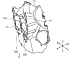
- FIG. 1 is a perspective view showing an engine according to an embodiment of the present invention.
- FIG. 1 is a diagram showing an engine according to an embodiment of the present invention, and is a perspective view showing a first engine block.
- FIG. 2 is a diagram showing an engine according to an embodiment of the present invention, and is a perspective view showing a second engine block.
- FIG. 1 is a diagram showing an engine according to an embodiment of the present invention, and is a perspective view showing an engine section.
- FIG. 2 is a diagram showing an engine according to an embodiment of the present invention, illustrating a contact surface of a first engine block.
- FIG. 2 is a diagram showing an engine according to an embodiment of the present invention, illustrating a contact surface of a second engine block.
- FIG. 1 is a diagram showing an engine according to an embodiment of the present invention, and is a perspective view showing a first engine block.
- FIG. 2 is a diagram showing an engine according to an embodiment of the present invention, illustrating a contact surface of a second engine
- FIG. 1 is a diagram showing an engine according to an embodiment of the present invention, and is a perspective view showing a cylinder chamber, each valve, etc.
- FIG. 1 is a diagram showing an engine according to an embodiment of the present invention, and is a perspective view showing a cylinder chamber, each valve, etc.
- FIG. 1 is a diagram showing an engine according to an embodiment of the present invention, and is a cross-sectional view showing a schematic configuration of a water jacket, etc.
- FIG. 2 is a cross-sectional view showing a wall portion of an engine block which defines a cylinder chamber and an extension space, showing an engine according to an embodiment of the present invention.
- FIG. 1 is a diagram showing an engine according to an embodiment of the present invention, and is a perspective view showing an engine block and a gasket.
- FIG. 2 is a diagram showing an engine according to an embodiment of the present invention, and is a plan view showing a gasket.
- FIG. 2 is a diagram showing an engine according to an embodiment of the present invention, and is a perspective view showing a water jacket and a gasket.
- FIG. 2 is a diagram showing an engine according to an embodiment of the present invention, and is a perspective view showing a water jacket and a gasket from a different angle.
- FIG. 1 is an exploded perspective view showing an engine according to an embodiment of the present invention, illustrating a water jacket and a gasket.
- FIG. 1 is a cutaway perspective view showing an engine according to an embodiment of the present invention, illustrating a water jacket and a gasket.
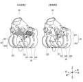
- FIG. 2 is a diagram showing an engine according to an embodiment of the present invention, illustrating the effect of water flow in a water jacket.
- the front-rear direction refers to the direction in which pistons, which will be described later, reciprocate.
- the left-right direction refers to the direction in which cylinder spaces, which will be described later, are arranged.
- the same components are generally given the same reference numerals, and repeated description will be omitted.
- the configuration described in the claims will be mainly illustrated and described. Therefore, parts of the engine 10 other than the relevant configuration, such as the plug, crankshaft rotation synchronization mechanism, lubricating oil supply mechanism, fuel supply mechanism, electrical equipment, etc., are not illustrated.
- Figure 1 is a perspective view of the engine 10.
- Engine 10 is an opposed-piston engine with multiple pistons arranged opposite each other. The internal configuration and operation of engine 10 will be described later with reference to FIG. 2A and subsequent figures. As will be described later, engine 10 mainly comprises an engine block 11, a cylinder chamber 12, and a water jacket 20.
- the engine 10 is configured to operate using gasoline, diesel, hydrogen, or the like as fuel.
- the engine 10 can be used as a drive source for various devices.
- the engine 10 is used as a drive source for vehicles, generators, water heaters, flying devices, drones, series hybrid drones, parallel hybrid drones, and the like.
- a series hybrid drone is a drone in which a generator is operated by the engine 10, a motor is rotated by the power generated by the generator, a rotor is rotated by the motor, and the aircraft is levitated in the air by the lift generated by the rotation of the rotor.
- a parallel hybrid drone is a drone in which a main rotor is mechanically rotated by the engine 10, and the aircraft is levitated by the lift generated by the rotation of the main rotor.
- the engine 10 of this embodiment is an opposed piston type engine, and is lightweight and has low vibration, making it suitable as a drive source for series hybrid drones, parallel hybrid drones, and the like.
- the engine 10 has an engine block 11, which is the main body.
- the engine block 11 is made of, for example, a cast aluminum alloy.
- the engine block 11 is made up of a first engine block 111, a second engine block 112, a third engine block 113, and a fourth engine block 114. Each of these parts is fastened to each other by fastening members (not shown).
- a third crankshaft 163 and a fourth crankshaft 173 extend from the right side of the engine 10. Rotational power can be extracted to the outside from the third crankshaft 163 and the fourth crankshaft 173.
- shafts can also be extended from the left side of the engine 10, and power can also be extracted to the outside from these shafts.
- FIG. 2A is a perspective view showing the first engine block 111.
- the surface of the first engine block 111 facing rearward is the first abutment surface 40.
- the first abutment surface 40 is a flat surface that abuts against a second abutment surface 41 of the second engine block 112, which will be described later.
- the first engine block 111 has a first cylinder chamber front portion 1211 and a second cylinder chamber front portion 1221 that are formed in a generally cylindrical shape extending forward from the first abutment surface 40.
- the first cylinder chamber front portion 1211 and the second cylinder chamber front portion 1221 are adjacent to each other in the left-right direction.
- the first cylinder chamber front portion 1211 is a generally cylindrical space and forms the front portion of the first cylinder chamber 121, which will be described later.
- the second cylinder chamber front portion 1221 is a generally cylindrical space and forms the front portion of the second cylinder chamber 122, which will be described later.
- the first extension space front portion 3311 is a portion of the first abutment surface 40 recessed forward, and is continuous with the upper end of the first cylinder chamber front portion 1211.
- the first extension space front portion 3311 constitutes the front portion of the first extension space 331 described below.
- the second extension space front portion 3321 is a portion of the first abutment surface 40 recessed forward, and is continuous with the upper end of the second cylinder chamber front portion 1221.
- the second extension space front portion 3321 constitutes the front portion of the second extension space 332 described below.
- the surface of the second engine block 112 facing forward is the second abutment surface 41.
- the second abutment surface 41 is a flat surface and abuts against the first abutment surface 40 of the first engine block 111 described above.
- the second engine block 112 has a first cylinder chamber rear portion 1212 and a second cylinder chamber rear portion 1222 formed rearward from the second abutment surface 41.
- the first cylinder chamber rear portion 1212 and the second cylinder chamber rear portion 1222 are adjacent to each other in the left-right direction.
- the first cylinder chamber rear portion 1212 is a roughly cylindrical space and forms the rear portion of the first cylinder chamber 121, which will be described later.
- the second cylinder chamber rear portion 1222 is a roughly cylindrical space and forms the rear portion of the second cylinder chamber 122, which will be described later.
- the first extension space rear portion 3312 is a portion of the second abutment surface 41 recessed toward the rear, and is continuous with the upper end of the first cylinder chamber rear portion 1212.
- the second extension space rear portion 3322 is a portion of the second abutment surface 41 recessed toward the rear, and is continuous with the upper end of the second cylinder chamber rear portion 1222.
- Figure 3 is a perspective view of the engine section 13 built into the engine block 11 described above, seen from the front.
- the spark plug 26 has an electrode formed at its tip that is disposed inside the extension space 33.
- the spark plug 26 has a first spark plug 261 and a second spark plug 262.
- the first spark plug 261 is a component disposed on the left side of the first exhaust valve 191.
- the front end of the first spark plug 261 is disposed inside the first extension space 331.
- the second spark plug 262 is a component disposed to the right of the second exhaust valve 192.
- the front end of the second spark plug 262 is disposed inside the second extension space 332.
- FIG. 6 is a cross-sectional view showing a schematic configuration of the water jacket 20, etc.
- FIG. 6 is a cross-section corresponding to the A-A cutting surface edge in FIG. 1.
- the boundary between the first engine block 111 and the second engine block 112 is shown by a dotted line.
- the engine block 11 has a first engine block 111, a second engine block 112, a third engine block 113 and a fourth engine block 114.
- the first cylinder chamber 121 is a space formed by joining the first engine block 111 and the second engine block 112. As described above, while the engine 10 is operating, the first piston 141 and the second piston 151 reciprocate inside the first cylinder chamber 121.
- the water jacket 20 is a space formed near the cylinder chamber 12 through which the cooling fluid 25 flows.
- the water jacket 20 is configured to cool the first cylinder chamber 121 and the second cylinder chamber 122.
- the configuration in which the water jacket 20 surrounds the first cylinder chamber 121 is illustrated.
- the second cylinder chamber 122 described above is also surrounded by the water jacket 20.
- the water jacket 20 has a first water jacket portion 206, a second water jacket portion 207, and a communication portion 208.
- the first water jacket portion 206 is a cavity formed in the thick portion of the first engine block 111.
- the first water jacket portion 206 is formed so as to surround the front portion of the first cylinder chamber 121 from the periphery.
- the first water jacket portion 206 is connected to the outside via the discharge portion 23.
- the second water jacket portion 207 is a cavity formed in the thick portion of the second engine block 112.
- the second water jacket portion 207 is formed so as to surround the rear portion of the first cylinder chamber 121 from the periphery.
- the second water jacket portion 207 is connected to the outside via the introduction portion 22.
- the communication section 208 is a space that communicates with the first water jacket section 206 and the second water jacket section 207 at the boundary shown by the dotted line, i.e., the boundary between the first engine block 111 and the second engine block 112.
- the cooling fluid 25 When the engine 10 is operating, the cooling fluid 25 is introduced through the inlet 22, flows through the second water jacket section 207, the communication section 208, and the first water jacket section 206, receives heat from the first cylinder chamber 121, and is taken out from the outlet 23.
- a fluid with a large specific heat such as water, can be used.
- a water jacket 20 is formed surrounding the second cylinder chamber 122 described above.
- FIG. 7 is a cross-sectional view taken along the line B-B in FIG. 3, showing the wall of the engine block 11 that defines the first cylinder chamber 121 and the first extension space 331.
- the first cylinder chamber 121 is a space having a substantially cylindrical shape.
- the first cylinder chamber 121 has a first cylinder chamber front portion 1211 on the front side, and a first cylinder chamber rear portion 1212 that is connected to the rear end of the first cylinder chamber front portion 1211.
- a first extension space 331 protrudes upward from the top surface of the first cylinder chamber 121 at approximately the center of the first cylinder chamber 121 in the front-to-rear direction.
- the first cylinder chamber front portion 1211, the first cylinder chamber rear portion 1212, and the first extension space 331 are in communication.
- the first cylinder chamber 121 and the first extension space 331 in this configuration are spaces surrounded by walls formed inside the engine block 11.
- the first cylinder chamber front portion 1211 is a substantially cylindrical space surrounded by the first cylinder wall portion 1281.
- the first cylinder wall portion 1281 is a cylindrical wall formed inside the first engine block 111.
- the front and rear ends of the first cylinder wall portion 1281 are open.
- the first cylinder chamber rear portion 1212 is a substantially cylindrical space surrounded by the second cylinder wall portion 2282.
- the second cylinder wall portion 2282 is a cylindrical wall formed inside the second engine block 112. The front and rear ends of the second cylinder wall portion 2282 are open.
- the first extension space 331 is a space surrounded by the first extension wall portion 1291 and the second extension wall portion 2292.
- the first extension wall portion 1291 is a roughly tongue-shaped portion that extends upward from the upper end portion of the first cylinder wall portion 1281 at the rear end of the first cylinder wall portion 1281.
- the second extension wall portion 2292 is a roughly tongue-shaped portion that extends upward from the upper end portion of the second cylinder wall portion 2282 at the front end of the second cylinder wall portion 2282.
- the first cylinder chamber 121 is a substantially cylindrical space having a first central axis 1213 extending along the front-rear direction.
- the first cylinder chamber 121 has a first side surface 1214.
- the first side surface 1214 is a surface formed by the inner surfaces of the first cylinder wall portion 1281 and the second cylinder wall portion 2282.
- a first extension space 331 extends from the first side surface 1214.
- the first extension space 331 is a space that extends upward, in a direction perpendicular to the first central axis 1213 of the first cylinder chamber 121.
- the first extension space 331 communicates with the first cylinder chamber 121.
- Figure 8 is an oblique view showing the engine block 11 and gasket 21.
- the engine block 11 has a first engine block 111 and a second engine block 112.
- the first abutment surface 40 of the first engine block 111 and the second abutment surface 41 of the second engine block 112 face each other in the front-rear direction.
- the gasket 21 is a generally plate-like member having a shape corresponding to the first abutment surface 40 and the second abutment surface 41.
- the gasket 21 is made of a metal plate and a resin layer covering the surface of the metal plate.
- the gasket 21 is disposed so as to be sandwiched between the first abutment surface 40 of the first engine block 111 and the second abutment surface 41 of the second engine block 112.
- the gasket 21 is a member that fills the gap between the first engine block 111 and the second engine block 112 and prevents liquid or gas from leaking out from between them.
- the gasket 21 has multiple openings. The openings are used for the circulation of the cooling fluid 25, the insertion of fastening members such as stud bolts, and the formation of the extension space 33 and the cylinder chamber 12.
- FIG. 9 is a plan view showing the gasket 21.
- the outer edge shape of the gasket 21 conforms to the first abutment surface 40 and the second abutment surface 41 shown in FIG. 8.
- the gasket 21 has a plurality of through openings. Specifically, the gasket 21 has a communication opening 211, a first cylinder opening 212, a second cylinder opening 213, and an insertion opening 214. In addition, a part of the gasket 21 is an isolating portion 215 that functions as a partial wall.
- the communication openings 211 are openings for allowing the cooling fluid 25 to flow.
- a plurality of communication openings 211 are formed along the periphery of the gasket 21.
- the position and shape of the communication openings 211 are similar to the communication openings 208 shown in FIG. 4A and the communication openings 209 shown in FIG. 4B.
- the communication openings 208 and 209 communicate with each other via the communication openings 211.
- the first cylinder opening 212 is a large opening formed on the left side of the gasket 21.
- the outer edge shape of the first cylinder opening 212 is similar to the outer edge shape of the first cylinder chamber 121 and the first extension space rear portion 3312 shown in FIG. 8.
- the second cylinder opening 213 is a large opening formed on the right side of the gasket 21.
- the outer edge shape of the second cylinder opening 213 is similar to the outer edge shape of the second cylinder chamber 122 and the second extension space rear portion 3322 shown in FIG. 8.
- the insertion opening 214 is a substantially circular opening formed in the gasket 21 between the first cylinder chamber 121 and the second cylinder opening 213.
- a stud bolt (not shown here) is inserted through the insertion opening 214. The stud bolt is used to fasten the first engine block 111 to the fourth engine block 114 shown in FIG. 1 together.
- FIG. 10A is a perspective view showing the water jacket 20 and gasket 21.
- FIG. 10B is a perspective view showing the water jacket 20 and gasket 21 from a different angle.
- FIG. 11 is an exploded perspective view showing the water jacket 20 and gasket 21.
- the water jacket 20 has an upper jacket portion 201, a lower jacket portion 202, and an intermediate communication portion 203.
- the water jacket 20 is a cavity formed in the thick portion surrounding the cylinder chamber 12 in the first engine block 111 and the second engine block 112.
- a cooling fluid 25 for example water, flows through the water jacket 20 to effectively cool the cylinder chamber 12, which repeats the explosion process.
- the water jacket 20 also has a first water jacket portion 206, a second water jacket portion 207, and a communication portion 208.
- the first water jacket portion 206 is made of a cavity formed in the first engine block 111 described above.
- the second water jacket portion 207 is made of a cavity formed in the second engine block 112 described above.
- the communication portion 208 is made of a cavity that connects to the communication portion 208 shown in FIG. 4A and the communication portion 209 shown in FIG. 4B.
- the communication portion 208 is a portion that connects the first water jacket portion 206 and the second water jacket portion 207, and is formed to pass through the communication opening 211 described above.
- the upper jacket portion 201 is configured to surround the upper portions of the first cylinder chamber 121 and the second cylinder chamber 122.
- the upper portion of the upper jacket portion 201 has a complex shape to avoid the valves mentioned above.
- the lower jacket portion 202 is configured to surround the lower portions of the first cylinder chamber 121 and the second cylinder chamber 122.
- the upper jacket portion 201 and the lower jacket portion 202 are continuous at both left and right ends.
- the intermediate communication part 203 is a part of the water jacket 20, and is disposed in the space sandwiched between the first cylinder chamber 121 and the second cylinder chamber 122 in the left-right direction.
- the intermediate communication part 203 is configured to communicate between the upper jacket part 201 and the lower jacket part 202. In this way, air present in the part of the lower jacket part 202 surrounded by the first cylinder chamber 121 and the second cylinder chamber 122 can flow to the upper jacket part 201 via the intermediate communication part 203.
- the cooling fluid 25 can be effectively circulated via the intermediate communication part 203.
- the intermediate communication portion 203 is shorter than the upper jacket portion 201 and the lower jacket portion 202.
- the intermediate communication portion 203 has a first intermediate communication portion 204 and a second intermediate communication portion 205.
- the first intermediate communication portion 204 is the intermediate communication portion 203 in the forward portion of the gasket 21.
- the second intermediate communication portion 205 is the intermediate communication portion 203 in the rear portion of the gasket 21.
- the first intermediate communication portion 204 connects the lower jacket portion 202 and the upper jacket portion 201 in the first water jacket portion 206.
- the second intermediate communication portion 205 connects the lower jacket portion 202 and the upper jacket portion 201 in the second water jacket portion 207.
- the first intermediate communication part 204 and the second intermediate communication part 205 can communicate the jacket lower part 202 and the jacket upper part 201 in both the first water jacket part 206 and the second water jacket part 207. Therefore, air retention can be suppressed in both the first water jacket part 206 and the second water jacket part 207, and the flow of the cooling fluid 25 can be promoted, so that the cylinder chamber 12 can be effectively cooled.
- FIG. 12 is a cutaway perspective view showing the water jacket 20 and gasket 21.
- the water jacket 20 is cut along a plane extending in the front-to-rear and up-to-down directions.
- the flow of the cooling fluid 25 is indicated by dashed arrows.
- the gasket 21 is disposed between the first water jacket portion 206 and the second water jacket portion 207.
- the portion of the gasket 21 existing between the first intermediate communication portion 204 and the second intermediate communication portion 205 corresponds to the isolating portion 215 shown in FIG. 9. In other words, no opening is formed in the gasket 21 in that portion.
- the cooling fluid 25 flows along the main surface of the gasket 21, allowing the gasket 21 to be cooled effectively.
- the cooling fluid 25 introduced into the jacket lower section 202 is supplied to the jacket upper section 201 via the first intermediate communication section 204.
- the cooling fluid 25 comes into contact with the front surface of the isolation section 215 of the gasket 21, thereby cooling the gasket 21.
- the cooling fluid 25 introduced into the jacket lower section 202 is supplied to the jacket upper section 201 via the second intermediate communication section 205.
- the cooling fluid 25 comes into contact with the rear surface of the isolation section 215 of the gasket 21, thereby cooling the gasket 21.
- the flow area of the intermediate communication section 203 for the flow of the cooling fluid 25 is smaller than the flow area of the lower jacket section 202 and the upper jacket section 201. Therefore, the flow rate of the cooling fluid 25 is faster in the intermediate communication section 203 than in the upper jacket section 201 and the lower jacket section 202. This also increases the effect of cooling the isolation section 215 of the gasket 21 by the cooling fluid 25 flowing at high speed.
- the isolating portion 215 is the central portion of the gasket 21, and is also the portion sandwiched between the first cylinder chamber 121 and the second cylinder chamber 122 described above. Therefore, the isolating portion 215 of the gasket 21 is in an environment that is prone to high temperatures.
- the cooling fluid 25 that flows vertically through the first intermediate communication portion 204 and the second intermediate communication portion 205 effectively cools the isolating portion 215 of the gasket 21, thereby preventing the portion from overheating.
- the intermediate communication part 203 is a cavity that connects the lower jacket part 202 and the upper jacket part 201, and is divided in the front-to-rear direction by the gasket 21. Therefore, the intermediate communication part 203 has the function of allowing the flow of the cooling fluid 25 in the up-down direction, but not allowing the flow of the cooling fluid 25 in the front-to-rear direction.
- a recessed portion is formed at the bottom between the two chambers. Therefore, unless some measures are taken, there is a concern that air will stagnate in that portion. Furthermore, in order to reduce the size of the engine 10, it is not possible to ensure a large gap between the first cylinder chamber 121 and the second cylinder chamber 122, and therefore it is not easy to cool the gap between the two chambers.
- an intermediate communication portion 203 is formed between the first cylinder chamber 121 and the second cylinder chamber 122 to prevent air from stagnation in that portion. Furthermore, a cooling fluid 25 is passed between the first cylinder chamber 121 and the second cylinder chamber 122 to effectively cool that portion.
- Figure 13 shows the effect of water flow in the water jacket 20.
- the comparative example on the left side is a comparative example that does not have the intermediate communication part 203 described above.
- the example on the right side has the intermediate communication part 203 described above.
- the flow rate distribution is shown by hatching, and the hatched parts have low flow rates.
- the intermediate communication portion 203 described above is not formed. Therefore, there is a hatched portion in the portion corresponding to the portion between the first cylinder chamber 121 and the second cylinder chamber 122. Therefore, in the water jacket 20 of the comparative example, there are some parts where the cooling fluid 25 does not flow or where the cooling fluid 25 stagnates. Therefore, there is a risk that these parts will not be sufficiently cooled by the cooling fluid 25 and will become heated.
Landscapes
- Engineering & Computer Science (AREA)
- Mechanical Engineering (AREA)
- General Engineering & Computer Science (AREA)
- Chemical & Material Sciences (AREA)
- Combustion & Propulsion (AREA)
- Cylinder Crankcases Of Internal Combustion Engines (AREA)
Priority Applications (2)
| Application Number | Priority Date | Filing Date | Title |
|---|---|---|---|
| JP2025538072A JPWO2025027735A1 (https=) | 2023-07-31 | 2023-07-31 | |
| PCT/JP2023/027908 WO2025027735A1 (ja) | 2023-07-31 | 2023-07-31 | エンジン |
Applications Claiming Priority (1)
| Application Number | Priority Date | Filing Date | Title |
|---|---|---|---|
| PCT/JP2023/027908 WO2025027735A1 (ja) | 2023-07-31 | 2023-07-31 | エンジン |
Publications (1)
| Publication Number | Publication Date |
|---|---|
| WO2025027735A1 true WO2025027735A1 (ja) | 2025-02-06 |
Family
ID=94394723
Family Applications (1)
| Application Number | Title | Priority Date | Filing Date |
|---|---|---|---|
| PCT/JP2023/027908 Pending WO2025027735A1 (ja) | 2023-07-31 | 2023-07-31 | エンジン |
Country Status (2)
| Country | Link |
|---|---|
| JP (1) | JPWO2025027735A1 (https=) |
| WO (1) | WO2025027735A1 (https=) |
Citations (7)
| Publication number | Priority date | Publication date | Assignee | Title |
|---|---|---|---|---|
| JPS60152041U (ja) * | 1984-03-19 | 1985-10-09 | 日産自動車株式会社 | 内燃機関のシリンダブロツク |
| JPH0893498A (ja) * | 1994-09-26 | 1996-04-09 | Teruo Mikawa | 水平対向エンジン |
| JPH10184358A (ja) * | 1996-12-27 | 1998-07-14 | Fuji Heavy Ind Ltd | 水冷式エンジンの冷却装置 |
| JP2000110580A (ja) * | 1998-10-05 | 2000-04-18 | Honda Motor Co Ltd | 多気筒エンジン |
| JP2007046534A (ja) * | 2005-08-10 | 2007-02-22 | Kumikawa Tekkosho:Kk | 対向エンジン |
| JP2012184769A (ja) * | 2005-02-24 | 2012-09-27 | John W Fitzgerald | 可変ピストンストローク式の4シリンダ、4サイクル、フリーピストン、予混合気圧縮点火型の内燃往復ピストンエンジン |
| JP5508604B2 (ja) * | 2011-09-30 | 2014-06-04 | 株式会社石川エナジーリサーチ | 対向ピストン型エンジン |
-
2023
- 2023-07-31 JP JP2025538072A patent/JPWO2025027735A1/ja active Pending
- 2023-07-31 WO PCT/JP2023/027908 patent/WO2025027735A1/ja active Pending
Patent Citations (7)
| Publication number | Priority date | Publication date | Assignee | Title |
|---|---|---|---|---|
| JPS60152041U (ja) * | 1984-03-19 | 1985-10-09 | 日産自動車株式会社 | 内燃機関のシリンダブロツク |
| JPH0893498A (ja) * | 1994-09-26 | 1996-04-09 | Teruo Mikawa | 水平対向エンジン |
| JPH10184358A (ja) * | 1996-12-27 | 1998-07-14 | Fuji Heavy Ind Ltd | 水冷式エンジンの冷却装置 |
| JP2000110580A (ja) * | 1998-10-05 | 2000-04-18 | Honda Motor Co Ltd | 多気筒エンジン |
| JP2012184769A (ja) * | 2005-02-24 | 2012-09-27 | John W Fitzgerald | 可変ピストンストローク式の4シリンダ、4サイクル、フリーピストン、予混合気圧縮点火型の内燃往復ピストンエンジン |
| JP2007046534A (ja) * | 2005-08-10 | 2007-02-22 | Kumikawa Tekkosho:Kk | 対向エンジン |
| JP5508604B2 (ja) * | 2011-09-30 | 2014-06-04 | 株式会社石川エナジーリサーチ | 対向ピストン型エンジン |
Also Published As
| Publication number | Publication date |
|---|---|
| JPWO2025027735A1 (https=) | 2025-02-06 |
Similar Documents
| Publication | Publication Date | Title |
|---|---|---|
| US10167810B2 (en) | Engine assembly | |
| IT201800004821A1 (it) | Motore a combustione interna ad alte prestazioni con gestione delle emissioni migliorata e metodo di controllo di tale motore | |
| US6295963B1 (en) | Four cycle engine for a marine propulsion system | |
| KR20120104367A (ko) | 로터리 내연 기관 | |
| EP3051092B1 (en) | Cooling of pre-chamber in internal combustion engine | |
| CN116104609A (zh) | 发动机系统 | |
| JP6476796B2 (ja) | 多気筒エンジンの冷却用オイル通路構造 | |
| US12448915B2 (en) | Engine | |
| CN109642479B (zh) | 十字头和构架、以及十字头式内燃机 | |
| WO2025027735A1 (ja) | エンジン | |
| US20240309799A1 (en) | Engine | |
| US6338660B1 (en) | Exhaust system for an outboard motor | |
| WO2025027731A1 (ja) | エンジン | |
| US2718221A (en) | Combustion chamber | |
| JP6888430B2 (ja) | エンジンの冷却用オイル通路構造 | |
| JP7633746B1 (ja) | エンジン | |
| US10286988B2 (en) | Outboard motor and marine vessel | |
| WO2025027733A1 (ja) | エンジン | |
| JPH07506650A (ja) | ピストン及びシリンダ装置 | |
| JP4676319B2 (ja) | 2サイクルエンジン | |
| WO2025027732A1 (ja) | エンジン | |
| JPH07217442A (ja) | ピストン組立体 | |
| WO2025027734A1 (ja) | エンジン | |
| JP6897347B2 (ja) | エンジンの冷却用オイル通路構造 | |
| US3034491A (en) | Internal combustion engine |
Legal Events
| Date | Code | Title | Description |
|---|---|---|---|
| 121 | Ep: the epo has been informed by wipo that ep was designated in this application |
Ref document number: 23947534 Country of ref document: EP Kind code of ref document: A1 |
|
| ENP | Entry into the national phase |
Ref document number: 2025538072 Country of ref document: JP Kind code of ref document: A |
|
| WWE | Wipo information: entry into national phase |
Ref document number: 2025538072 Country of ref document: JP |
|
| NENP | Non-entry into the national phase |
Ref country code: DE |