WO2025023306A1 - 光ファイバテープ心線および光ファイバテープ心線の製造方法 - Google Patents
光ファイバテープ心線および光ファイバテープ心線の製造方法 Download PDFInfo
- Publication number
- WO2025023306A1 WO2025023306A1 PCT/JP2024/026681 JP2024026681W WO2025023306A1 WO 2025023306 A1 WO2025023306 A1 WO 2025023306A1 JP 2024026681 W JP2024026681 W JP 2024026681W WO 2025023306 A1 WO2025023306 A1 WO 2025023306A1
- Authority
- WO
- WIPO (PCT)
- Prior art keywords
- light irradiation
- core
- cores
- irradiation surface
- fiber
- Prior art date
- Legal status (The legal status is an assumption and is not a legal conclusion. Google has not performed a legal analysis and makes no representation as to the accuracy of the status listed.)
- Pending
Links
Images


Classifications
-
- G—PHYSICS
- G02—OPTICS
- G02B—OPTICAL ELEMENTS, SYSTEMS OR APPARATUS
- G02B6/00—Light guides; Structural details of arrangements comprising light guides and other optical elements, e.g. couplings
- G02B6/02—Optical fibres with cladding with or without a coating
-
- G—PHYSICS
- G02—OPTICS
- G02B—OPTICAL ELEMENTS, SYSTEMS OR APPARATUS
- G02B6/00—Light guides; Structural details of arrangements comprising light guides and other optical elements, e.g. couplings
- G02B6/44—Mechanical structures for providing tensile strength and external protection for fibres, e.g. optical transmission cables
Definitions
- the present disclosure relates to an optical fiber ribbon and a method for manufacturing an optical fiber ribbon.
- This application claims priority based on Japanese Application No. 2023-120735 filed on July 25, 2023, and incorporates by reference all of the contents of said Japanese application.
- Patent Document 1 discloses a type of tape core wire that includes multiple multi-core fibers and allows each fiber to be separated, and a manufacturing method thereof.
- Patent Document 2 discloses a method for aligning a multi-core fiber. In the alignment method described in Patent Document 2, illumination light is applied to the side of the multi-core fiber and the displacement of the shadow of the core is detected by an imaging device. This allows the twist of the multi-core fiber to be detected, and the twist is eliminated using a twist elimination pulley.
- Patent Document 3 discloses a tape core wire of a different type from the tape core wire of Patent Document 1.
- An optical fiber ribbon includes a first multicore fiber having a plurality of first cores and a first clad covering the plurality of first cores, a second multicore fiber having a plurality of second cores and a second clad covering the plurality of second cores and arranged in parallel to the first multicore fiber, and a coating member at least partially covering the first multicore fiber and the second multicore fiber.
- the coating member has a first coating portion that coats the first multicore fiber and a second coating portion that coats the second multicore fiber.
- a first light irradiation surface having a width greater than the diameter of the first core is provided in at least one region where a virtual line passing through at least two or more of the plurality of first cores or a virtual line passing through the center of the first multicore fiber intersects with the outer periphery of the first coating portion.
- This first light irradiation surface includes a curved surface or a flat surface having a radius of curvature of 0.5 mm or more.
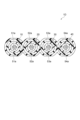
- FIG. 1 is a cross-sectional view showing an optical fiber ribbon according to an embodiment.
- FIG. 2 is a diagram showing a method for manufacturing the optical fiber ribbon shown in FIG.
- FIG. 3 is a diagram for explaining a method of core alignment by light irradiation in a general multi-core fiber.
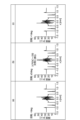
- Parts (a), (b) and (c) of FIG. 4 are diagrams showing the measurement results of symmetry in the core alignment shown in FIG.
- FIG. 5 is a diagram showing an example of the relationship between asymmetry and the rotation angle.
- Part (a) of Figure 6 is an example showing the transmission state of light irradiated when there is no uneven distribution of coating resin in the ribbon core
- part (b) of Figure 6 is an example showing the transmission state of light irradiated when there is uneven distribution of coating resin in the ribbon core
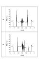
- Part (a) of Figure 7 is a diagram showing the measurement results of symmetry in the core alignment shown in part (a) of Figure 6
- part (b) of Figure 7 is a diagram showing the measurement results of symmetry in the core alignment shown in part (b) of Figure 6.
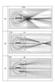
- Parts (a), (b), and (c) of Figure 8 are examples showing the light transmission state when the coating resin of the ribbon core is unevenly distributed, and the light transmission state is changed to a general multi-core fiber, a multi-core fiber whose light irradiation surface is a curved surface with a large radius of curvature, and a multi-core fiber whose light irradiation surface is a flat surface.
- FIG. 9 is a diagram showing the relationship between the asymmetry in a multi-core fiber and the radius of curvature of the light irradiation surface when the radius of curvature of the light irradiation surface is changed.
- FIG. 10 is a graph showing the measurement results of symmetry when light is irradiated onto a multi-core fiber having the structure shown in part (c) of FIG.
- Parts (a), (b), and (c) of Figure 11 are examples showing the light transmission state when the coating resin of the ribbon core is unevenly distributed, and when the light transmission state is changed to a general multi-core fiber, a multi-core fiber having a light irradiation surface on one side, and a multi-core fiber having a light irradiation surface on both sides.
- FIG. 12 is a diagram showing the relationship between the asymmetry and the radius of curvature of the light irradiation surface in the multi-core fiber shown in parts (a) to (c) of FIG.
- Parts (a), (b) and (c) of FIG. 13 are diagrams showing an example of the positional relationship between the installation position of the light irradiation surface and each core.
- Parts (a), (b) and (c) of FIG. 14 are diagrams showing another example of the positional relationship between the installation position of the light irradiation surface and each core.
- FIG. 15 is a cross-sectional view showing a first modified example of the optical fiber ribbon.
- FIG. 16 is a cross-sectional view showing a second modified example of the optical fiber ribbon.
- various resins covering the clad in each multi-core fiber may be unevenly distributed (so-called uneven thickness portions may be formed).
- Such resins are, for example, a primary resin layer or a secondary resin layer covering the clad, or a resin layer that covers the fibers collectively. If the resin is unevenly distributed in this way, even if the arrangement of the cores in each fiber is uniform, the alignment may not go well, for example, when performing core alignment by light irradiation, due to the influence of the uneven distribution of resin.
- An optical fiber ribbon includes a first multicore fiber having a plurality of first cores and a first clad covering the plurality of first cores, a second multicore fiber having a plurality of second cores and a second clad covering the plurality of second cores and arranged in parallel to the first multicore fiber, and a coating member at least partially covering the first multicore fiber and the second multicore fiber.
- the coating member has a first coating portion covering the first multicore fiber and a second coating portion covering the second multicore fiber.
- a first light irradiation surface having a width greater than the diameter of the first core is provided in at least one region where a virtual line passing through at least two or more first cores among the plurality of first cores or a virtual line passing through the center of the first multicore fiber intersects with an outer periphery of the first coating portion.
- the first light irradiation surface includes a curved surface or a flat surface having a radius of curvature of 0.5 mm or more.
- a first light irradiation surface having a width greater than the diameter of the first core is provided in at least one region where a virtual line passing through at least two or more of the multiple first cores or a virtual line passing through the center of the first multicore fiber intersects with the outer periphery of the first coating portion.
- This first light irradiation surface includes a curved surface or a flat surface having a radius of curvature of 0.5 mm or more.
- this optical fiber ribbon can be a ribbon in which the alignment of the multiple first cores is reliably performed.
- a second light irradiation surface having a width greater than the diameter of the second core may be provided in at least one region where a virtual line passing through at least two or more of the multiple second cores or a virtual line passing through the center of the second multicore fiber intersects with the outer periphery of the second coating portion.
- This second light irradiation surface may include a curved surface or a flat surface having a curvature radius of 0.5 mm or more.
- a ribbon core wire can be obtained in which, in addition to the alignment of the multiple first cores, the alignment of the multiple second cores is also reliably performed.
- the normal direction of the first light irradiation surface at the intersection of the first light irradiation surface and the virtual line may be the same as the normal direction of the second light irradiation surface at the intersection of the second light irradiation surface and the virtual line.
- the illumination light for the alignment work of each core in the first multi-core fiber and the second multi-core fiber can be irradiated from the same direction. Therefore, it is possible to provide an optical fiber ribbon core wire that can easily perform alignment in a ribbon core wire including multiple multi-core fibers.
- the "same direction” here does not only mean the completely same direction, but also allows for a slight deviation, for example a deviation of about ⁇ 1°, between the normal direction of the first light irradiation surface and the normal direction of the second light irradiation surface.
- the axis of the virtual line and the normal direction of the first light irradiation surface may be oriented in the same direction.
- the same direction here does not only mean that they are exactly the same direction, but also means that there may be some deviation between the axis of the virtual line and the normal direction of the first light irradiation surface, for example, a deviation of about ⁇ 1°.
- the arrangement of the multiple first cores may be linearly symmetrical with respect to a virtual line passing through the center of the first multicore fiber, at least in the range corresponding to the first light irradiation surface.
- the light transmitted through the optical fiber can be made into a symmetrical brightness graph.
- the arrangement of the multiple first cores may be linearly symmetrical with respect to a virtual line passing through the center of the first multicore fiber.
- the light transmitted through the optical fiber can be made into a symmetrical brightness graph.
- the width of the first light irradiation surface may be 20 ⁇ m or more longer than the diameter of the first core.
- the resin which is a constituent element, may be unevenly distributed, but this is acceptable as a product if, for example, the core center shifts by about 10 ⁇ m from the specified position (no change in thickness rate of 70%). Therefore, even in a ribbon core wire with such uneven resin distribution, by providing a first light irradiation surface of the above-mentioned width, it is possible to reduce the effect of the uneven distribution and obtain a ribbon core wire with reliable alignment of the first core.
- the virtual line may pass through at least three or more first cores.
- the light for alignment passes through more cores, improving alignment accuracy, and a ribbon core having more reliable alignment can be obtained in a ribbon core including multiple multicore fibers.
- the three or more first cores referred to here may include a marker core that has a higher refractive index than the cladding portion, like a normal first core, but does not have a trench or the like formed on the outer periphery of the cladding.
- the first light irradiation surface may be provided in each of two opposing regions where the imaginary lines intersect on the outer periphery of the first coating portion.
- the transmitted light will have more symmetry, so that a ribbon including multiple multicore fibers that can be easily aligned can be provided.
- the optical fiber ribbon according to any one of [1] to [9] above may further include a third multicore fiber having a plurality of third cores and a third clad covering the plurality of third cores, and a fourth multicore fiber having a plurality of fourth cores and a fourth clad covering the plurality of fourth cores.
- the first multicore fiber, the second multicore fiber, the third multicore fiber, and the fourth multicore fiber may be arranged in parallel in this order, and the coating member may cover the third multicore fiber and the fourth multicore fiber together with the first multicore fiber and the second multicore fiber.
- the coating member may further include a third coating portion that coats the third multicore fiber and a fourth coating portion that coats the fourth multicore fiber.
- a recess may be provided at least one between the first coating portion and the second coating portion, between the second coating portion and the third coating portion, and between the third coating portion and the fourth coating portion.
- a third light irradiation surface having a width longer than the diameter of the third core may be provided in a region where a virtual line passing through at least two or more third cores among the plurality of third cores or a virtual line passing through the center of the third multicore fiber intersects with the outer periphery of the third coating portion, and this third light irradiation surface may include a curved surface or a flat surface having a curvature radius of 0.5 mm or more.
- a fourth light irradiation surface having a width longer than the diameter of the fourth core may be provided in a region where a virtual line passing through at least two or more fourth cores among the plurality of fourth cores or a virtual line passing through the center of the fourth multicore fiber intersects with the outer periphery of the fourth coating portion, and this fourth light irradiation surface may include a curved surface or a flat surface having a curvature radius of 0.5 mm or more.
- this optical fiber ribbon even if the number of cores in the optical fiber ribbon increases to four, the ribbon can be easily aligned.
- a recess is provided between at least one of the first and second coated portions, between the second and third coated portions, and between the third and fourth coated portions, so that each fiber can be easily separated.
- the normal direction of the first light irradiation surface at the intersection of the first light irradiation surface and the virtual line, the normal direction of the second light irradiation surface at the intersection of the second light irradiation surface and the virtual line, the normal direction of the third light irradiation surface at the intersection of the third light irradiation surface and the virtual line, and the normal direction of the fourth light irradiation surface at the intersection of the fourth light irradiation surface and the virtual line may all face the same direction.
- the illumination light for the alignment work of each core in the first multi-core fiber, the second multi-core fiber, the third multi-core fiber, and the fourth multi-core fiber can be irradiated from the same direction. Therefore, it is possible to provide an optical fiber ribbon core wire that can easily perform alignment in a ribbon core wire including multiple multi-core fibers.
- the "same direction" here does not only mean the completely same direction, but also allows for a slight deviation between each normal direction, for example, a deviation of about ⁇ 1°.
- a method for manufacturing an optical fiber ribbon includes the steps of: preparing a first multicore fiber having a plurality of first cores and a first clad covering the plurality of first cores; preparing a second multicore fiber having a plurality of second cores and a second clad covering the plurality of second cores; coating the first and second multicore fibers with resin while arranging the first and second multicore fibers in parallel; and irradiating light onto a light irradiation surface in a coating resin portion that coats the first multicore fiber, and aligning the plurality of first cores in the first multicore fiber based on the result of the light irradiation.
- the light irradiation surface is a surface provided in a region where a virtual line passing through at least two or more of the plurality of first cores or a virtual line passing through the center of the first multicore fiber intersects with the outer periphery of the coating resin portion, and the light irradiation surface includes a curved surface or a flat surface having a width greater than the diameter of the first core and a radius of curvature of 0.5 mm or more.
- This optical fiber ribbon manufacturing method includes a step of irradiating light onto a light irradiation surface in a coating resin portion that coats the first multicore fiber, and aligning the first cores in the first multicore fiber based on the result of the light irradiation.
- the light irradiation surface is a surface provided in a region where a virtual line passing through at least two or more of the first cores among the multiple first cores or a virtual line passing through the center of the first multicore fiber intersects with the outer periphery of the coating resin portion, and the light irradiation surface has a width greater than the diameter of the first core and includes a curved surface or a flat surface with a curvature radius of 0.5 mm or more.
- FIG. 1 is a cross-sectional view showing an optical fiber tape core wire according to an embodiment.
- the optical fiber tape core wire 1 includes a plurality of multi-core fibers 10, 20, 30, 40 and a coating member 50.
- the multi-core fibers 10 to 40 extend along a first direction D1.
- the multi-core fibers 10 to 40 are arranged in parallel along a second direction D2 and are entirely covered by a coating member 50.
- the optical fiber tape core wire 1 is, for example, a four-core tape core wire, and recesses 55, 56, 57 are provided between each fiber so that the fibers can be separated into individual fibers. Note that in this four-core tape core wire, the recess 56 is provided but the recesses 55 and 57 are not provided, and the tape core wire may be formed from two pairs of fibers (see the modified example in FIG. 16).
- the multicore fiber 10 (first multicore fiber) has a plurality of cores 11 (a plurality of first cores), a clad 12 (first clad) covering the plurality of cores 11, a primary resin layer 13 covering the clad 12, and a secondary resin layer 14 covering the primary resin layer 13.
- 12 cores 11 are arranged in the order of 2, 4, 4, and 2, in line symmetry with respect to a virtual line passing through the center of the multicore fiber 10.
- the 12 cores 11 may be arranged line symmetrically with respect to a virtual line passing through the center of the multicore fiber 10 in the ranges corresponding to each of the light irradiation surfaces 51a to 54a described later.
- the diameter of the core 11 may be, for example, 5 ⁇ m to 15 ⁇ m.
- the diameter of the clad 12 may be, for example, 120 ⁇ m to 130 ⁇ m, or 170 ⁇ m to 190 ⁇ m.
- the number of cores in the core 11 is 12 in the example shown in FIG. 1, but is not limited to this and may be 16 (see FIG. 14) or another number of cores.
- the core 11 is made of pure silica (SiO 2 ) glass or a material in which germanium dioxide or fluorine is added to silica glass.
- the cladding 12 has a refractive index lower than that of the core 11.
- the cladding 12 is made of, for example, pure silica glass or a material in which fluorine is added to silica glass.
- a trench having a refractive index lower than that of the cladding 12 may be provided between each core 11 and the cladding 12.
- the primary resin layer 13 coats the outer periphery of the clad 12. More specifically, the primary resin layer 13 is in contact with the outer peripheral surface of the clad 12, and coats the entire clad 12.
- the secondary resin layer 14 further coats the outer periphery of the primary resin layer 13. More specifically, the secondary resin layer 14 is in contact with the outer peripheral surface of the primary resin layer 13, and coats the entire primary resin layer 13.
- the primary resin layer 13 can be formed by curing an ultraviolet-curable resin composition containing a photopolymerizable compound, a photopolymerization initiator, and a silane coupling agent.
- urethane (meth)acrylate or epoxy (meth)acrylate can be used as the photopolymerizable compound.
- the secondary resin layer 14 can be formed by curing a resin composition containing urethane (meth)acrylate, a monomer, and a photopolymerization initiator.
- the secondary resin layer 14 has a higher elasticity than the primary resin layer 13, and the secondary resin layer 14 is harder than the primary resin layer 13.
- the thickness of each layer of the primary resin layer 13 and the secondary resin layer 14 is, for example, 5 ⁇ m or more and 50 ⁇ m or less.
- the multicore fiber 20 (second multicore fiber) has a plurality of cores 21 (a plurality of second cores), a clad 22 (second clad) covering the plurality of cores 21, a primary resin layer 23 covering the clad 22, and a secondary resin layer 24 covering the primary resin layer 23, similar to the multicore fiber 10.
- the multicore fiber 30 (third multicore fiber) has a plurality of cores 31 (a plurality of third cores), a clad 32 (third clad) covering the plurality of cores 31, a primary resin layer 33 covering the clad 32, and a secondary resin layer 34 covering the primary resin layer 33, similar to the multicore fiber 10.
- the multicore fiber 40 (fourth multicore fiber) has a plurality of cores 41 (a plurality of fourth cores), a clad 42 (fourth clad) covering the plurality of cores 41, a primary resin layer 43 covering the clad 42, and a secondary resin layer 44 covering the primary resin layer 43, similar to the multicore fiber 10.
- Each core, clad, primary resin layer, and secondary resin layer of each multicore fiber 20, 30, and 40 has the same structure as each core 11, clad 12, primary resin layer 13, and secondary resin layer 14 of multicore fiber 10, respectively, so detailed description is omitted.
- the coating member 50 is formed from a ribbon resin.
- the ribbon resin may contain a thermosetting resin such as a silicone resin, an epoxy resin, or a urethane resin, or an ultraviolet-curing resin such as an epoxy acrylate, a urethane acrylate, or a polyester acrylate, from the viewpoint of preventing damage to the optical fiber and facilitating its severing.
- the coating member 50 has a first coating portion 51 that covers the multicore fiber 10, a second coating portion 52 that covers the multicore fiber 20, a third coating portion 53 that covers the multicore fiber 30, and a fourth coating portion 54 that covers the multicore fiber 40.
- Each coating portion 51 to 54 is in contact with the outer circumferential surface of the corresponding multicore fiber (the outer circumferential surface of each secondary resin layer, and the outer circumferential surface of the colored ink layer if there is a colored ink layer), and covers the entirety of each multicore fiber.
- the coating member 50 covers each multicore fiber to an extent that the user does not unintentionally separate it, and the coating member 50 may have a structure that partially covers the corresponding multicore fiber without covering the entirety of the multicore fiber.
- the first coated portion 51 has a shape that generally corresponds to the outer peripheral shape of the coated multi-core fiber 10, and has, for example, a substantially circular cross-sectional shape.
- the second coated portion 52, the third coated portion 53, and the fourth coated portion 54 have shapes that generally correspond to the outer peripheral shapes of the coated multi-core fiber 20, the multi-core fiber 30, and the multi-core fiber 40, respectively, and have, for example, a substantially circular cross-sectional shape.
- the first covered portion 51, the second covered portion 52, the third covered portion 53, and the fourth covered portion 54 each have a light irradiation surface 51a, 52a, 53a, and 54a formed from a flat surface.
- the light irradiation surfaces 51a to 54a may not be flat, but may be curved surfaces with a radius of curvature of 0.5 mm or more (see, for example, part (b) in FIG. 8).
- the radius of curvature may be larger than the radius of the curved surface of the portions of each covered portion 51 to 54 other than the light irradiation surfaces 51a to 54a.
- the radius of curvature can also be considered to be infinite.
- the light irradiation surface 51a is provided in a region where a virtual line passing through two or more cores 11a or a virtual line passing through two or more cores 11b, or a virtual line (center line) passing through the center of the multi-core fiber 10 intersects with the outer periphery of the first coated portion 51.
- the light irradiation surface 51a is provided on one side of the third direction D3 (upward in the figure) with respect to the core 11.
- the light irradiation surfaces 52a, 53a, and 54a are provided in regions where a virtual line passing through two or more cores 21, 31, and 41, or a virtual line (center line) passing through the center of the multi-core fiber 20, 30, and 40 intersects with the outer periphery of the second coated portion 52, the third coated portion 53, and the fourth coated portion 54, respectively.
- the width of such light irradiation surfaces 51a, 52a, 53a, 54a along the second direction D2 is longer than the diameter of the cores 11, 21, 31, 41 of each multi-core fiber 10, 20, 30, 40.
- the width of the light irradiation surfaces 51a, 52a, 53a, 54a along the second direction D2 may be equal to or greater than the diameter of the cores 11, 21, 31, 41 of each multi-core fiber 10, 20, 30, 40 plus 20 ⁇ m.
- the width of the light irradiation surfaces 51a, 52a, 53a, 54a along the second direction D2 may be longer than the center distance (core pitch) between two cores 11 (e.g., core 11a and core 11b), 21, 31, 41 located in the center of each multi-core fiber 10, 20, 30, 40 and adjacent in the second direction.
- each of the light irradiation surfaces 51a, 52a, 53a, and 54a is formed to face the same direction (upward in the third direction D3).
- the light irradiation surfaces 51a to 54a are formed so that the normal direction of the light irradiation surface 51a at the intersection of the light irradiation surface 51a and the virtual line in the multi-core fiber 10, the normal direction of the light irradiation surface 52a at the intersection of the light irradiation surface 52a and the virtual line in the multi-core fiber 20, the normal direction of the light irradiation surface 53a at the intersection of the light irradiation surface 53a and the virtual line in the multi-core fiber 30, and the normal direction of the light irradiation surface 54a at the intersection of the light irradiation surface 54a and the virtual line in the multi-core fiber 40 face in the same direction.
- the "same direction" not only refers to the case where each normal direction is completely the same direction, but also allows for a slight deviation between each normal direction, for example, a deviation of about ⁇ 1°.
- Any of the light irradiation surfaces 51a to 54a may be formed to face in a direction different from the other light irradiation surfaces.
- one light irradiation surface 51a to 54a is provided on each of the covered parts 51 to 54, but two or more light irradiation surfaces may be provided.
- two light irradiation surfaces 51a may be provided on the covered parts 51 that face each other in the third direction D3 (see, for example, FIG. 15).
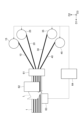
- FIG. 2 is a schematic diagram showing a method for manufacturing the optical fiber ribbon 1 shown in FIG. 1.
- the multicore fibers 10, 20, 30, and 40 are prepared. Each of the multicore fibers 10, 20, 30, and 40 is wound around the corresponding supply rolls 15, 25, 35, and 45, respectively, with each fiber being pulled out from each roll.
- the multi-core fibers 10, 20, 30, 40 thus drawn out from each of the supply rolls 15, 25, 35, 45 are arranged in parallel to one another along the second direction D2 in the die 61 and are coated with resin.
- This resin is a ribbon resin that forms the coating member 50, and contains a thermosetting resin such as silicone resin, epoxy resin, or urethane resin, or an ultraviolet-curing resin such as epoxy acrylate, urethane acrylate, or polyester acrylate.
- a resin is introduced into the die 61, and the ribbon resin is applied to cover the multi-core fibers 10, 20, 30, 40 aligned in the die 61.
- the applied resin is then irradiated with ultraviolet light (not shown) to harden the ribbon resin.
- the molding holes located inside the die 61 and through which the multi-core fibers 10, 20, 30, 40 pass have a cross-sectional shape that corresponds to the outer shape of the coating member 50 shown in FIG. 1.
- the light irradiation surface 51a, 52a, 53a, 54a in the coating resin portion coating the multi-core fibers 10, 20, 30, 40 is irradiated with illumination light L from the light irradiation device 62, and the light receiving device 63 receives brightness data, which is the shadow of the light transmitted through the optical fiber ribbon 1.
- the light receiving device 63 is, for example, a camera.
- the light received by the light receiving device 63 can be expressed as brightness data shown, for example, in parts (a) to (c) of FIG. 4.
- the brightness data shown in parts (a) to (c) of FIG. 4 is a graph of brightness data corresponding to the multi-core fiber. By detecting whether such a graph of brightness data has symmetry, it is possible to determine whether the arrangement of the cores in each of the multi-core fibers 10, 20, 30, 40 is uniform.
- the multiple cores in each multicore fiber 10, 20, 30, 40 are aligned.
- the brightness data from the light receiving device 63 is analyzed by the control device 64, and the angles of each supply roll 15, 25, 35, 45 are fine-tuned by a motor (not shown) or the like so that the brightness data has symmetry based on the analysis results. This adjusts the positions of the cores.
- such illumination light L is irradiated onto light irradiation surfaces 51a, 52a, 53a, and 54a provided corresponding to each of the multi-core fibers 10, 20, 30, and 40.
- these light irradiation surfaces 51a to 54a are flat surfaces having a predetermined width or curved surfaces having a curvature radius of 0.5 mm or more. Therefore, even if there is uneven distribution of resin in each of the multi-core fibers 10, 20, 30, and 40, the effect on the symmetry of the brightness data of the light passing through the fiber is reduced. Below, it will be explained that even if there is uneven distribution of resin (uneven thickness portion), the effect on the alignment of the cores is reduced by providing such light irradiation surfaces.
- FIG. 3 is a diagram for explaining core alignment by light irradiation in a general multi-core fiber.
- Parts (a), (b), and (c) of Fig. 4 are diagrams showing the measurement results of the symmetry in the core alignment shown in Fig. 3, and show the cases where the alignment angles are -1 deg, ⁇ 0 deg, and +1 deg, respectively. As shown in Fig.
- a general multi-core fiber 110 has multiple cores 111, cladding 112, primary resin layer 113, and secondary resin layer 114.
- Illumination light L is irradiated from the side of such a multi-core fiber 110, and the transmitted light is received by a camera, which is a light receiving device, to perform observation.
- a graph of the brightness data received by such a camera is, for example, as shown in parts (a) to (c) of Figure 4.
- the multi-core fiber 110 is slightly rotated in the plus (+) or minus (-) direction shown in Figure 3 to align it so that the graph of such brightness data has symmetry as shown in part (b) of Figure 4.
- the symmetry of such luminance data can also be shown, for example, as an asymmetry graph as shown in FIG. 5.
- the value obtained by integrating the square of the difference between the normal signal of the luminance data and the signal obtained by flipping the luminance data horizontally is displayed. If the luminance data is completely symmetrical, the value is 0, and the value increases as the asymmetry increases. It has been empirically found that when the asymmetry value is, for example, 0.2 or less, the arrangement of the cores in the multicore fiber is uniform and appropriate. However, as shown in FIG. 6B, the resin outside the cladding 112 may be unevenly distributed.
- FIG. 6A shows a case where there is no uneven distribution. As shown in FIG.
- FIG. 6A when there is no uneven distribution of the resin, and as shown in FIG. 7A, when the core arrangement is uniform, symmetrical luminance data can be obtained.
- FIG. 6B when there is uneven distribution of the resin, although the cores 111 themselves are uniform, as shown in FIG. 7B, the symmetry of the luminance data is lost, resulting in asymmetric luminance data. In this case, if one were to look only at the brightness data, it could be determined that the cores 111 of the multicore fiber 110A are not aligned.
- Parts (a), (b) and (c) of Figure 8 show examples of the light transmission state when the coating resin of the ribbon core is unevenly distributed and the light irradiation surface is changed to a curved surface with a large radius of curvature or a flat surface.
- Part (a) of Figure 8 shows the general multi-core fiber 110A described above
- parts (b) and (c) of Figure 8 show multi-core fibers provided with a light irradiation surface corresponding to the present embodiment described above.
- Parts (a), (b) and (c) of Figure 8 all have the same core arrangement.
- Figure 9 is a diagram showing the relationship between the asymmetry in each aspect shown in parts (a) to (c) of Figure 8 and the radius of curvature of the light irradiation surface.
- the transmitted illumination light will be distorted (asymmetric), but it has been found from simulations that when a curved light irradiation surface 51A with a curvature radius of 0.5 mm or more is provided on the optical fiber ribbon 1A as shown in part (b) of Figure 8, the illumination light will maintain symmetry. Similarly, it has been found from simulations that when a flat light irradiation surface 51B with an infinite curvature radius is provided on the optical fiber ribbon 1B as shown in part (c) of Figure 8, the illumination light will maintain symmetry.
- Figure 9 shows a table plotting the asymmetry when the curvature of the curved surface forming the light irradiation surface 51A is changed.
- the radius of curvature to 0.5 mm or more
- the asymmetry value in the transmitted light when the illumination light L is irradiated onto the multicore fiber can be set to the above-mentioned specified value of 0.2 or less.
- Figure 10 shows luminance data when the light irradiation surface 51B is formed from a flat surface as shown in part (c) of Figure 8.
- a graph with beautiful symmetry can be obtained as long as the cores are aligned, even if there is uneven distribution of resin.
- Part (a) of FIG. 11 shows the transmission state when illumination light is irradiated onto a general multi-core fiber 110A in the case where there is uneven distribution of resin
- part (b) of FIG. 11 shows the transmission state when illumination light is irradiated onto a multi-core fiber (optical fiber tape core 1C) with a light irradiation surface 51B provided on one side in the case where there is uneven distribution of resin
- FIG. 11 shows the transmission state when illumination light is irradiated onto a multi-core fiber with a light irradiation surface 51B provided on both sides in the case where there is uneven distribution of resin.
- the cores are aligned.
- the transmitted light has symmetry when there is uneven distribution of resin and a flat light irradiation surface 51B is provided on either one side or both sides.
- FIG. 12 the asymmetry values in the multicore fiber shown in parts (a), (b), and (c) of FIG. 11 are plotted. As is clear from FIG.
- the asymmetry value is significantly smaller than the reference value of 0.2.
- the asymmetry value is even lower than when the light irradiation surface 51B is provided on one surface. In other words, it is clear that core alignment can be performed more reliably when the light irradiation surface 51B is provided on both surfaces.
- the asymmetry value is sufficiently small even when the light irradiation surface 51B is provided on one surface, it is clear that core alignment can be performed reliably even when the light irradiation surface 51B is provided on one surface.
- a light irradiation surface having a width greater than the diameter of the core in the region where a virtual line passing through at least two or more cores or a virtual line (center line) passing through the center of the multi-core fiber intersects with the outer periphery of the coating, and by including a curved or flat surface with a curvature radius of 0.5 mm or more, it is understood that core alignment can be performed without problems even if the resin around the cladding is unevenly distributed.
- Fig. 13 describes an example of an optical fiber ribbon core wire 201 having a multi-core fiber 210.
- Fig. 13 shows only one multi-core fiber 210, but the optical fiber ribbon core wire 201 has multiple multi-core fibers 210.
- the multi-core fiber shown in Fig. 13 has 12 cores 211.
- Parts (a) and (b) of Fig. 14 describe an example of an optical fiber ribbon core wire 301 having a multi-core fiber 310.
- FIG. 14 describes an example of an optical fiber ribbon core wire 401 having a multi-core fiber 410.
- Fig. 14 shows only one multi-core fiber 310, 410, but the optical fiber ribbon core wires 301, 401 have multiple multi-core fibers 310, 410.
- the multicore fiber 310 shown in parts (a) and (b) of Figure 14 has 16 cores 311.
- the multicore fiber 410 shown in part (c) of Figure 14 has 12 cores 411 and one core marker 411b.
- a flat light irradiation surface 251a is formed in the region where an imaginary line A1 passing through four cores 211 in a row shifted to the right from the center intersects with the outer periphery of the covering portion 251.
- the axis of the imaginary line A1 faces in the same direction as the normal direction of the light irradiation surface 251a.
- the width of this light irradiation surface 251a is 20 ⁇ m or more longer than the diameter of the core 211.
- the light irradiation surface 251a may not be a flat surface, but may be a curved surface having a large radius of curvature of 0.5 mm or more. The same applies to the following examples. With the structure of this example, it is easy to select and align the cores that are the target of core alignment.
- a flat light irradiation surface 251a is formed in the region where a virtual line A2 (center line) passing between four cores 211a in a row shifted leftward from the center and four cores 211b in a row shifted rightward from the center intersects with the outer periphery of the coating portion 251.
- the virtual line A2 passes through the center of the multicore fiber 210.
- the axis of the virtual line A2 faces in the same direction as the normal direction of the light irradiation surface 251a.
- the width of this light irradiation surface 251a is 20 ⁇ m or more longer than the diameter of the core 211 (cores 211a, 211b). According to the structure of this example, although the signal of the luminance data through which the irradiation light passes becomes weaker, it is easier to obtain symmetry.
- the multi-core fiber 210 shown in part (a) of FIG. 13 is rotated 45 degrees.
- a flat light irradiation surface 251a is formed in the area where a virtual line A3 passing through two cores 211c on a center line passing through the center of the fiber intersects with the outer periphery of the coating portion 251.
- the axis of the virtual line A3 faces in the same direction as the normal direction of the light irradiation surface 251a.
- the width of this light irradiation surface 251a is 20 ⁇ m or more longer than the diameter of the core 211 (core 211c). According to the structure of this example, it is possible to select and align the cores to be targeted for core alignment, and to improve the symmetry of the luminance data of the transmitted illumination light.
- a flat light irradiation surface 351a is formed in the region where a virtual line B1 (center line) passing through four cores 311a on a center line passing through the center of the multicore fiber 310 intersects with the outer periphery of the coating portion 351.
- the axis of the virtual line B1 faces in the same direction as the normal direction of the light irradiation surface 351a.
- the width of this light irradiation surface 351a is 20 ⁇ m or more longer than the diameter of the core 311 (core 311a).
- the light irradiation surface 351a may not be a flat surface, but may be a curved surface having a large radius of curvature of 0.5 mm or more. The same applies to the following examples. According to the structure of this example, it is possible to select and align the cores to be targeted for core alignment, and to improve the symmetry of the luminance data through which the illumination light has passed.
- a light irradiation surface 351a made of a plane is formed in the region where a virtual line B2 passing through four cores 311a on a center line passing through the center of the multi-core fiber 310 intersects with the outer circumference of the coating portion 351, as in the example shown in FIG. 14(a).
- the axis of the virtual line B2 faces in the same direction as the normal direction of the light irradiation surface 351a.
- the pitch between the core 311a on the center line and the core 311b located on the outside is formed to be larger than the other core pitches.
- the rest of the structure is the same as the example shown in FIG. 14(a).
- the interval between the core 311a to be aligned and the non-aligned cores 311b, etc. is widened, so that overlapping of the cores during rotation during alignment can be reduced, and alignment can be performed with high precision.
- a core marker 411b is further provided for the multi-core fiber 210 shown in part (c) of FIG. 13, and a flat light irradiation surface 451a is formed in the area where a virtual line B3 (center line) passing through two cores 411a on the center line passing through the center of the fiber and the core marker 411b intersects with the outer periphery of the coating portion 451.
- the axis of the virtual line B3 faces in the same direction as the normal direction of the light irradiation surface 451a.
- the width of this light irradiation surface 451a is 20 ⁇ m or more longer than the diameter of the core 411a and the core marker 411b.
- light irradiation surfaces 51a, 52a, 53a, and 54a having a width greater than the diameter of the cores are provided in the region where a virtual line passing through at least two or more of the multiple cores 11, 21, 31, and 41 or a virtual line (center line, etc.) passing through the center of each multi-core fiber intersects with the outer periphery of the coating portion 51, 52, 53, and 54.
- These light irradiation surfaces 51a to 54a are curved or flat surfaces having a radius of curvature of 0.5 mm or more.
- this optical fiber ribbon 1 Furthermore, in this optical fiber ribbon 1, recesses 55, 56, and 57 are provided between each coated portion. This allows each fiber to be easily separated. In other words, it can be used as a ribbon that can be separated into single fibers.
- the light irradiation surfaces 51a, 52a, 53a, and 54a face in the same direction. Therefore, the illumination light L for the alignment of each core in each of the multi-core fibers 10, 20, 30, and 40 can be irradiated from the same direction. This makes it possible to provide an optical fiber ribbon that allows easy alignment in a ribbon including multiple multi-core fibers.
- the width of each light irradiation surface 51a, 52a, 53a, 54a is 20 ⁇ m or more longer than the diameter of each core 11, 21, 31, 41.
- the resin which is a constituent element, may be unevenly distributed, but this is acceptable as a product if, for example, the core center shifts by about 10 ⁇ m from the specified position (no change in thickness rate of 70%). Therefore, even in a tape core wire with such uneven resin distribution, by providing light irradiation surfaces 51a to 54a with the above-mentioned widths, the effect of the uneven distribution can be reduced, and a tape core wire with reliable core alignment can be obtained.
- the virtual line that defines the positions of the light irradiation surfaces 51a, 52a, 53a, and 54a may pass through at least three or more cores.
- the ribbon including multiple multi-core fibers can be more reliably aligned.
- all of the light irradiation surfaces 51a, 52a, 53a, and 54a may be flat. In this case, the accuracy of forming each light irradiation surface can be easily improved.
- the optical fiber ribbon 1 and its manufacturing method according to the present disclosure have been described in detail above, but the present invention is not limited to the above embodiment and can be applied to various embodiments and modified examples.
- the light irradiation surface 51a, 52a, 53a, 54a is provided on one side of each of the multi-core fibers 10, 20, 30, 40, but as shown in FIG. 15, the optical fiber ribbon 1D may have the light irradiation surfaces 51a to 54a provided on both sides of each of the multi-core fibers 10, 20, 30, 40.
- each of the light irradiation surfaces 51a to 54a may be a flat surface or a curved surface having a radius of curvature of 0.5 mm or more.
- an optical fiber ribbon core wire consisting of four (or two pairs) multi-core fibers has been described, but the present disclosure is not limited to this. In other words, it is clear to those skilled in the art that the contents of the present disclosure can be applied to any optical fiber ribbon core wire that includes two or more multi-core fibers.
- an optical fiber ribbon core wire 1E may be provided with 12 (or six pairs) multi-core fibers 10, 20, 30, 40 (optical fibers), which is more than four (or two pairs).
- Multicore fiber first multi-core fiber
- 11a, 11b...Core first core
- 12 ... Clad (first clad) 13, 23, 33, 43... Primary resin layers 14, 24, 34, 44... Secondary resin layers 15, 25, 35, 45... Supply roll
- Multicore fiber second multicore fiber 21...Core (second core) 22...
Landscapes
- Physics & Mathematics (AREA)
- General Physics & Mathematics (AREA)
- Optics & Photonics (AREA)
- Optical Fibers, Optical Fiber Cores, And Optical Fiber Bundles (AREA)
Priority Applications (1)
| Application Number | Priority Date | Filing Date | Title |
|---|---|---|---|
| JP2025535874A JPWO2025023306A1 (https=) | 2023-07-25 | 2024-07-25 |
Applications Claiming Priority (2)
| Application Number | Priority Date | Filing Date | Title |
|---|---|---|---|
| JP2023120735 | 2023-07-25 | ||
| JP2023-120735 | 2023-07-25 |
Publications (1)
| Publication Number | Publication Date |
|---|---|
| WO2025023306A1 true WO2025023306A1 (ja) | 2025-01-30 |
Family
ID=94375424
Family Applications (1)
| Application Number | Title | Priority Date | Filing Date |
|---|---|---|---|
| PCT/JP2024/026681 Pending WO2025023306A1 (ja) | 2023-07-25 | 2024-07-25 | 光ファイバテープ心線および光ファイバテープ心線の製造方法 |
Country Status (2)
| Country | Link |
|---|---|
| JP (1) | JPWO2025023306A1 (https=) |
| WO (1) | WO2025023306A1 (https=) |
Citations (10)
| Publication number | Priority date | Publication date | Assignee | Title |
|---|---|---|---|---|
| US20130322835A1 (en) * | 2012-05-31 | 2013-12-05 | Douglas L. Butler | Angular alignment of optical fibers for fiber optic ribbon cables, and related methods |
| JP2014133673A (ja) | 2013-01-09 | 2014-07-24 | Hitachi Metals Ltd | ファイバ素線製造装置及びテープ心線 |
| WO2016047658A1 (ja) | 2014-09-24 | 2016-03-31 | 古河電気工業株式会社 | テープ心線およびテープ心線の製造方法 |
| US20160223774A1 (en) * | 2013-11-22 | 2016-08-04 | Corning Cable Systems, Llc | Multicore optical fibers and methods of manufacturing the same |
| JP2017173514A (ja) | 2016-03-23 | 2017-09-28 | 古河電気工業株式会社 | 光ファイバテープ心線および光ファイバテープ心線の製造方法 |
| JP2018526687A (ja) * | 2015-07-31 | 2018-09-13 | コーニング オプティカル コミュニケイションズ リミテッド ライアビリティ カンパニー | ロール可能な光ファイバリボン |
| WO2022065485A1 (ja) * | 2020-09-28 | 2022-03-31 | 住友電気工業株式会社 | 光ファイバケーブルおよびコネクタ付きケーブル |
| WO2022254986A1 (ja) * | 2021-06-04 | 2022-12-08 | 住友電気工業株式会社 | 光ファイバの製造方法、光ファイバ、光ファイバリボンの製造方法、光ファイバリボン、光ファイバの製造装置、及び、光ファイバリボンの製造装置 |
| US20230152513A1 (en) * | 2021-11-12 | 2023-05-18 | Corning Incorporated | Reduced clad dual-core optical fibers for optical fiber cables and optical fiber interconnects |
| JP2023120735A (ja) | 2022-02-18 | 2023-08-30 | プライムプラネットエナジー&ソリューションズ株式会社 | 電力取引支援装置 |
-
2024
- 2024-07-25 JP JP2025535874A patent/JPWO2025023306A1/ja active Pending
- 2024-07-25 WO PCT/JP2024/026681 patent/WO2025023306A1/ja active Pending
Patent Citations (10)
| Publication number | Priority date | Publication date | Assignee | Title |
|---|---|---|---|---|
| US20130322835A1 (en) * | 2012-05-31 | 2013-12-05 | Douglas L. Butler | Angular alignment of optical fibers for fiber optic ribbon cables, and related methods |
| JP2014133673A (ja) | 2013-01-09 | 2014-07-24 | Hitachi Metals Ltd | ファイバ素線製造装置及びテープ心線 |
| US20160223774A1 (en) * | 2013-11-22 | 2016-08-04 | Corning Cable Systems, Llc | Multicore optical fibers and methods of manufacturing the same |
| WO2016047658A1 (ja) | 2014-09-24 | 2016-03-31 | 古河電気工業株式会社 | テープ心線およびテープ心線の製造方法 |
| JP2018526687A (ja) * | 2015-07-31 | 2018-09-13 | コーニング オプティカル コミュニケイションズ リミテッド ライアビリティ カンパニー | ロール可能な光ファイバリボン |
| JP2017173514A (ja) | 2016-03-23 | 2017-09-28 | 古河電気工業株式会社 | 光ファイバテープ心線および光ファイバテープ心線の製造方法 |
| WO2022065485A1 (ja) * | 2020-09-28 | 2022-03-31 | 住友電気工業株式会社 | 光ファイバケーブルおよびコネクタ付きケーブル |
| WO2022254986A1 (ja) * | 2021-06-04 | 2022-12-08 | 住友電気工業株式会社 | 光ファイバの製造方法、光ファイバ、光ファイバリボンの製造方法、光ファイバリボン、光ファイバの製造装置、及び、光ファイバリボンの製造装置 |
| US20230152513A1 (en) * | 2021-11-12 | 2023-05-18 | Corning Incorporated | Reduced clad dual-core optical fibers for optical fiber cables and optical fiber interconnects |
| JP2023120735A (ja) | 2022-02-18 | 2023-08-30 | プライムプラネットエナジー&ソリューションズ株式会社 | 電力取引支援装置 |
Also Published As
| Publication number | Publication date |
|---|---|
| JPWO2025023306A1 (https=) | 2025-01-30 |
Similar Documents
| Publication | Publication Date | Title |
|---|---|---|
| CN100430767C (zh) | 具有优先分离顺序的光纤带 | |
| US8023790B2 (en) | Optical waveguide film with mark for positioning and method for producing the same | |
| EP2995980B1 (en) | Optical fiber ribbon core and optical fiber cable | |
| US9453979B2 (en) | Multi-core optical fiber tape | |
| CN101027588A (zh) | 具有一个或多个优先破裂部分的光纤带及其制造方法 | |
| EP2056147B1 (en) | Optical fiber ribbon | |
| JP4383342B2 (ja) | 不均一な厚さおよび/または優先的な切り裂き部分を有する光ファイバリボン | |
| CN113933992A (zh) | 近眼显示设备和光学结构及其晶圆级别的制备方法 | |
| US20090080848A1 (en) | Optical waveguide and method for manufacturing the same | |
| JP2001159726A (ja) | 裂くことが可能な光ファイバリボン | |
| WO2025023306A1 (ja) | 光ファイバテープ心線および光ファイバテープ心線の製造方法 | |
| JP7297643B2 (ja) | 光ファイバテープ心線の製造方法及び光ファイバテープ心線の製造装置 | |
| US20250224554A1 (en) | Optical fiber, optical fiber ribbon, and method of manufacturing optical fiber | |
| WO2025023257A1 (ja) | 光ファイバテープ心線および光ファイバテープ心線の製造方法 | |
| EP1386892A1 (en) | Optical fiber and method of manufacturing the optical fiber | |
| JP5947967B2 (ja) | 光ファイバテープ心線及び光ファイバケーブル | |
| WO2024095531A1 (ja) | マルチコア光ファイバの調心装置、マルチコア光ファイバリボンの製造装置、マルチコア光ファイバユニットの製造装置、マルチコア光ファイバの調心方法、マルチコア光ファイバリボンの製造方法、マルチコア光ファイバユニットの製造方法、マルチコア光ファイバリボンの検査装置、及びマルチコア光ファイバリボンの検査方法 | |
| WO2025263438A1 (ja) | 光ファイバ、光ファイバ平型素線、光ファイバテープ心線、および、光ファイバテープ心線の製造方法 | |
| JP4247946B2 (ja) | 光ファイバテープ心線集合体、光ファイバテープ心線用樹脂被覆装置及び光ファイバテープ心線の樹脂被覆方法 | |
| JP2025123678A (ja) | テープファイバおよびテープファイバの製造方法 | |
| EP4703782A1 (en) | Optical fiber ribbon | |
| JPWO2025023306A5 (https=) | ||
| JP3383022B2 (ja) | 光ファイバテープ心線の製造方法 | |
| WO2025173711A1 (ja) | 光ファイバ、光ファイバの製造方法、テープファイバ、および、テープファイバの製造方法 | |
| CN121899988A (zh) | 一种光纤柔性板布纤方法 |
Legal Events
| Date | Code | Title | Description |
|---|---|---|---|
| 121 | Ep: the epo has been informed by wipo that ep was designated in this application |
Ref document number: 24845680 Country of ref document: EP Kind code of ref document: A1 |
|
| ENP | Entry into the national phase |
Ref document number: 2025535874 Country of ref document: JP Kind code of ref document: A |
|
| WWE | Wipo information: entry into national phase |
Ref document number: 2025535874 Country of ref document: JP |
|
| WWE | Wipo information: entry into national phase |
Ref document number: 2024845680 Country of ref document: EP |
|
| NENP | Non-entry into the national phase |
Ref country code: DE |