WO2025023266A1 - ドリル及び切削加工物の製造方法 - Google Patents
ドリル及び切削加工物の製造方法 Download PDFInfo
- Publication number
- WO2025023266A1 WO2025023266A1 PCT/JP2024/026396 JP2024026396W WO2025023266A1 WO 2025023266 A1 WO2025023266 A1 WO 2025023266A1 JP 2024026396 W JP2024026396 W JP 2024026396W WO 2025023266 A1 WO2025023266 A1 WO 2025023266A1
- Authority
- WO
- WIPO (PCT)
- Prior art keywords
- drill
- rotation
- region
- discharge groove
- margin surface
- Prior art date
- Legal status (The legal status is an assumption and is not a legal conclusion. Google has not performed a legal analysis and makes no representation as to the accuracy of the status listed.)
- Pending
Links
Images




Classifications
-
- B—PERFORMING OPERATIONS; TRANSPORTING
- B23—MACHINE TOOLS; METAL-WORKING NOT OTHERWISE PROVIDED FOR
- B23B—TURNING; BORING
- B23B51/00—Tools for drilling machines
Definitions
- This disclosure relates to a method for manufacturing drills and machined products.
- Patent Document 1 A drill (hole-making tool) described in JP-A-7-040117 (Patent Document 1) is known as a drill used when performing turning on a workpiece.
- the drill described in Patent Document 1 has a first margin and a second margin. Having multiple margins in this way improves the straight-line stability of the drill.
- the end portion of the tip portion that is located forward in the direction of rotation is located closer to the rear end of the drill than the end portion that is located backward in the direction of rotation.
- the above-described configuration of the second margin allows the tip portion to function as a scraping edge.
- Patent Document 1 The tip of the second margin in Patent Document 1 is prone to a relatively large cutting load. Therefore, there is a demand for further improvement in the durability of the second margin.
- the non-limiting one-sided drill of the present disclosure has a rod-shaped body extending along a rotation axis from a tip to a rear end.
- the body has a first cutting edge located on the tip side, a second cutting edge located on the tip side and rearward of the first cutting edge in the rotation direction of the rotation axis, a clearance surface extending rearward in the rotation direction from the first cutting edge, a first discharge groove extending from the first cutting edge toward the rear end, a second discharge groove extending from the second cutting edge toward the rear end, and an outer peripheral surface located between the first discharge groove and the second discharge groove and extending from the clearance surface toward the rear end.
- the outer peripheral surface has a front margin surface extending along the first discharge groove, a rear margin surface extending along the second discharge groove, and a clearance surface located between the front margin surface and the rear margin surface.
- the ridgelines of the rear margin surface and the clearance surface extend toward the rear end as they move forward in the direction of rotation.
- the ridgeline includes an end portion of the ridgeline located forward in the direction of rotation, and has a convex curved portion that protrudes forward in the direction of rotation.
- FIG. 1 is a perspective view of a non-limiting one sided drill of the present disclosure.
- FIG. 2 is an enlarged view of a region II shown in FIG. 1 .
- FIG. 3 is an enlarged view of region III shown in FIG. 2 .
- FIG. 2 is a side view of the drill shown in FIG. 1 .
- FIG. 5 is an enlarged view of a region V shown in FIG. 4 .
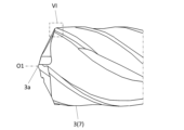
- FIG. 6 is an enlarged view of region VI shown in FIG. 5 .
- 7 is a cross-sectional view of the VII section of the drill shown in FIG. 4 .
- FIG. 8 is an enlarged view of region VIII shown in FIG. 7 .
- FIG. 4 is a perspective view of a non-limiting one-sided drill of the present disclosure, the view corresponding to FIG. 3; FIG.
- FIG. 10 is a side view of the drill shown in FIG. 9 and corresponds to FIG. 6 .
- 9 is a cross-sectional view of a non-limiting one-sided drill of the present disclosure, the view corresponding to FIG. 8 .
- FIG. 2 is a schematic diagram showing a step in a non-limiting method of manufacturing a one-sided machined product according to the present disclosure.
- FIG. 2 is a schematic diagram showing a step in a non-limiting method of manufacturing a one-sided machined product according to the present disclosure.
- FIG. 2 is a schematic diagram showing a step in a non-limiting method of manufacturing a one-sided machined product according to the present disclosure.
- the non-limiting one-sided drill 1 of the present disclosure will be described in detail with reference to the drawings.
- the drill 1 may include any component members not shown in each of the drawings referred to.
- the dimensions of the components in each drawing do not faithfully represent the dimensions of the actual components and the dimensional ratios of each component.
- a solid drill may be shown as an example of the drill 1.
- the drill 1 is not limited to a solid drill and may be, for example, a replaceable tip drill.
- the drill 1 may have a body 3, as shown in a non-limiting example in Figs. 1 to 8.
- the body 3 may be rod-shaped extending along the rotation axis O1 from the tip 3a to the rear end 3b.
- the body 3 is rotatable around the rotation axis O1.
- the arrow Y1 in Fig. 1 etc. may indicate the direction of rotation of the rotation axis O1, or may indicate the direction of rotation of the body 3 around the rotation axis O1.
- the main body 3 may have a shank portion 5 and a cutting portion 7.
- the shank portion 5 may function as a portion that is gripped by a rotating spindle of a machine tool.
- the shank portion 5 may be designed according to the shape of the spindle in the machine tool.
- the cutting portion 7 may be located on the tip 3a side relative to the shank portion 5.
- the cutting portion 7 is capable of contacting the workpiece and can function as a portion that plays a major role in cutting the workpiece (e.g., drilling).
- the main body 3 is not limited to a specific size.
- the maximum value of D may be set to approximately 2 to 50 mm.
- the main body 3 may have a first cutting edge 9, a second cutting edge 11, a clearance surface 13, a first discharge groove 15, a second discharge groove 17, and an outer peripheral surface 19, as shown in a non-limiting example in FIG. 2. These parts may be located in the cutting section 7.
- the first cutting edge 9 may be located on the side of the tip 3a.
- the first cutting edge 9 may function as a part that cuts the workpiece during cutting.
- the first cutting edge 9 may also be called the main cutting edge.
- the second cutting edge 11 may be located on the tip 3a side, rearward of the first cutting edge 9 in the rotation direction Y1 of the rotation axis O1.
- the second cutting edge 11 may function as a part that cuts the workpiece in the cutting process.
- the second cutting edge 11 may also be called a main cutting edge.
- the second cutting edge 11 may have the same configuration as the first cutting edge 9.
- first cutting edge 9 and the second cutting edge 11 There may be only one each of the first cutting edge 9 and the second cutting edge 11, or there may be multiple each of them. When there are multiple each of the first cutting edge 9 and the second cutting edge 11, they may be positioned alternately in the direction along the rotation direction Y1.
- the first cutting edge 9 and the second cutting edge 11 may be positioned so as to be rotationally symmetrical at 180° with respect to the rotation axis O1.
- the drill 1 has high linearity when cutting the workpiece.
- the flank 13 may extend rearward from the first cutting edge 9 in the rotational direction Y1.
- the flank 13 may function as a portion that avoids contact with the workpiece and reduces cutting resistance.
- the flank 13 may be connected to the first cutting edge 9.
- the flank 13 may have a second flank 21 and a third flank 23.
- the second flank 21 may be located along the first cutting edge 9.
- the second flank 21 may also be connected to the first cutting edge 9.
- the second flank 21 may be flat.
- the third flank 23 may be located along the second flank 21 at the rear in the rotational direction Y1.
- the third flank 23 may also be connected to the second flank 21.
- the third flank 23 may be inclined with respect to the second flank 21.
- the third flank 23 may be flat.
- the first discharge groove 15 may extend from the first cutting edge 9 toward the rear end 3b.
- the first discharge groove 15 may function as a portion for discharging chips generated by the first cutting edge 9 to the outside.
- the first discharge groove 15 may extend parallel to the rotation axis O1, or may extend in a spiral shape around the rotation axis O1.
- the number of first discharge grooves 15 may be the same as the number of first cutting edges 9.
- the first discharge groove 15 may be connected to the first cutting edge 9. In this case, the bite into the workpiece is strong. A rake face connecting the first discharge groove 15 and the first cutting edge 9 may be located between them. In this case, the discharge direction of the chips generated by the first cutting edge 9 is likely to be stable. From the viewpoint of smoothly discharging the chips to the outside, the first discharge groove 15 may have a concave curved shape in a cross section perpendicular to the rotation axis O1.
- the second discharge groove 17 may extend from the second cutting edge 11 toward the rear end 3b.
- the second discharge groove 17 may function as a portion for discharging chips generated by the second cutting edge 11 to the outside.
- the second discharge groove 17 may extend parallel to the rotation axis O1, or may extend in a spiral shape around the rotation axis O1.
- the number of second discharge grooves 17 may be the same as the number of second cutting edges 11.
- each of the first discharge groove 15 and the second discharge groove 17 is not limited to a specific value.
- the depth of the first discharge groove 15 may be set to 1.5 to 10% of the outer diameter of the main body 3 (cutting portion 7), and the depth of the second discharge groove 17 may be set to 15 to 40%.
- the depth of the first discharge groove 15 may be the value obtained by subtracting the distance between the bottom of the first discharge groove 15 and the rotation axis O1 from the radius of the main body 3 (cutting portion 7) in a cross section perpendicular to the rotation axis O1.
- the bottom of the first discharge groove 15 may be the portion of the first discharge groove 15 that is closest to the rotation axis O1.
- the depth of the second discharge groove 17 may be defined in the same way as the depth of the first discharge groove 15.
- the outer peripheral surface 19 may be located between the first discharge groove 15 and the second discharge groove 17.
- the outer peripheral surface 19 may extend from the clearance surface 13 toward the rear end 3b.
- the outer peripheral surface 19 may be connected to the first discharge groove 15 and the second discharge groove 17.
- the outer peripheral surface 19 may be connected to the clearance surface 13.
- the outer peripheral surface 19 may have a forward margin surface 25, a rearward margin surface 27, and a clearance surface 29.
- the front margin surface 25 may extend along the first discharge groove 15.
- the rear margin surface 27 may extend along the second discharge groove 17.
- the front margin surface 25 and the rear margin surface 27 can function as portions that slide against the inner wall surface of the machined hole in the workpiece to stabilize the operability of the drill 1.
- the straight-line stability of the drill 1 is high.
- the front margin surface 25 and the rear margin surface 27 may be arc-shaped portions that correspond to the outer periphery of the main body 3.
- the clearance surface 29 may be located between the front margin surface 25 and the rear margin surface 27.
- the clearance surface 29 may function as a portion that reduces friction with the workpiece during cutting.
- the clearance surface 29 may be recessed relative to the front margin surface 25 and the rear margin surface 27.
- the clearance surface 29 may be connected to the front margin surface 25 and the rear margin surface 27.
- the ridge 31 of the rear margin surface 27 and the clearance surface 13 may extend toward the rear end 3b as it moves forward in the rotation direction Y1, as in the non-limiting example shown in FIG. 6.
- This configuration may be evaluated in a side view.
- a side view may refer to a state seen from a direction perpendicular to the rotation axis O1. If the ridge 31 extends toward the rear end 3b as it moves forward in the rotation direction Y1, the ridge 31 may function as a scraping edge.
- the ridge line 31 may further have a straight portion 35, as shown in a non-limiting example in FIG. 6.
- the straight portion 35 may extend rearward in the rotational direction Y1 from the convex curved portion 33. In this case, it is easy to avoid the ridge line 31 rubbing against the workpiece more than necessary. This can reduce the cutting resistance, suppress wear of the ridge line 31, and easily improve the life of the drill 1.
- the straight line portion 35 may be connected to the convex curve portion 33.
- the straight line portion 35 may also include the end 31b of the ridge line 31 located rearward in the rotational direction Y1.
- the end 31a located forward in the rotational direction Y1 may be located closer to the rear end 3b than the end 31b located rearward in the rotational direction Y1.
- the end 31a may be referred to as the first end 31a, and the end 31b may be referred to as the second end 31b.
- the width W35 of the straight portion 35 in the direction along the rotation direction Y1 may be the same as the width W33 of the convex curved portion 33 in the direction along the rotation direction Y1, or may be different.
- the width W35 of the straight portion 35 may be greater than the width W33 of the convex curved portion 33.
- the width W35 of the straight portion 35 and the width W33 of the convex curved portion 33 are not limited to any particular value.
- the outer peripheral surface 19 may further have a chamfered region 37, as shown in a non-limiting example in FIG. 3.
- the chamfered region 37 may be sandwiched between the second discharge groove 17 and the rear margin surface 27. In this case, stress concentration between the rear margin surface 27 and the second discharge groove 17 can be alleviated, making it easier to reduce the risk of sudden breakage.
- the chamfered region 37 may be connected to the second discharge groove 17 and the rear margin surface 27. As shown in a non-limiting example in FIG. 8, the chamfered region 37 may have a linear shape in a cross section perpendicular to the rotation axis O1. The chamfered region 37 may be inclined with respect to the rear margin surface 27.
- the clearance surface 29 may have a rear region 39, as shown in a non-limiting example in FIG. 8.
- the rear region 39 may be connected to the rear margin surface 27.
- the rear region 39 may have a concave curved shape. In these cases, fine chips generated during cutting can be discharged to the outside via the concave curved rear region 39. This makes it difficult for chips to get caught in the rear margin surface 27, and the main body 3 is less likely to be damaged.
- the angle ⁇ 1 between the rear region 39 and the rear margin surface 27 may be the same as the angle ⁇ 2 between the chamfer region 37 and the rear margin surface 27, or they may be different.
- the angle ⁇ 1 in a cross section perpendicular to the rotation axis O1, the angle ⁇ 1 may be smaller than the angle ⁇ 2. In this case, a wide space can be secured for the rear region 39 located forward of the rear margin surface 27 in the rotation direction Y1, making it easier to flow a large amount of chips into the rear region 39.
- a tangent line may be set at the boundary with the rear margin surface 27, and the angle ⁇ 1 between the rear region 39 and the rear margin surface 27 may be determined by the angle at which this tangent line intersects with the rear margin surface 27.
- the angle ⁇ 1 between the rear region 39 and the rear margin surface 27, and the angle ⁇ 2 between the chamfer region 37 and the rear margin surface 27 may each be an obtuse angle.
- the rigidity of the drill 1 can be increased, and the hole drilling process can be stabilized.
- Angle ⁇ 1 and angle ⁇ 2 are not limited to specific values.
- angle ⁇ 1 may be set to 60 to 145°, and angle ⁇ 2 may be set to 80 to 155°.
- angle ⁇ 1 may be referred to as the first angle ⁇ 1
- angle ⁇ 2 may be referred to as the second angle ⁇ 2.
- the width W37 of the chamfered region 37 in the direction along the rotation direction Y1 may be the same as or different from the width W27 of the rear margin surface 27 in the direction along the rotation direction Y1.
- the width W37 of the chamfered region 37 may be smaller than the width W27 of the rear margin surface 27.
- the rear margin surface 27 and the second discharge groove 17 are close to each other, so that the rear margin surface 27 can stably function as a margin.
- the width W37 of the chamfered region 37 and the width W27 of the rear margin surface 27 are not limited to any particular value.
- the width W37 of the chamfered region 37 may be set to 1-10% of the total length of the outer periphery of the main body 3 (cutting portion 7), and the width W27 of the rear margin surface 27 may be set to 3-10%.
- the width W27 of the rear margin surface 27 may be greater than the width W25 of the front margin surface 25 in the direction along the rotation direction Y1. Also, in a cross section perpendicular to the rotation axis O1, the width W29 of the clearance surface 29 in the direction along the rotation direction Y1 may be greater than the width W25 of the front margin surface 25 and the width W27 of the rear margin surface 27.
- the width W25 of the front margin surface 25 and the width W29 of the clearance surface 29 are not limited to specific values.
- the width W25 of the front margin surface 25 may be set to 3-8% of the total length of the outer periphery of the main body 3 (cutting portion 7), and the width W29 of the clearance surface 29 may be set to 10-25%.
- the flank 13 may have a convex curved region 41 extending from the convex curved portion 33 toward the rotation axis O1, as in a non-limiting example shown in FIG. 3.
- the region 41 may extend forward in the rotation direction Y1 as it moves away from the convex curved portion 33.
- the width of the region 41 in the direction along the rotation axis O1 may decrease as it approaches the rotation axis O1.
- the region 41 may be connected to the convex curved portion 33.
- the region 41 may be connected to the third flank 23.
- the region 41 may be separated from the second flank 21.
- the material of the main body 3 may be, for example, a cemented carbide or a cermet.
- the composition of the cemented carbide may be, for example, WC-Co, WC-TiC-Co, or WC-TiC-TaC-Co.
- WC, TiC, and TaC may be hard particles
- Co may be a binder phase.
- the cermet may be a sintered composite material in which a ceramic component is combined with a metal.
- the cermet may be a titanium compound whose main component is titanium carbide (TiC) or titanium nitride (TiN).
- TiC titanium carbide
- TiN titanium nitride
- the above materials are only non-limiting examples, and the main body 3 is not limited to these materials.
- the surface of the body 3 may be coated with a coating using a chemical vapor deposition (CVD) method or a physical vapor deposition ( PVD ) method.
- the composition of the coating may include, for example, titanium carbide (TiC), titanium nitride (TiN), titanium carbonitride (TiCN), and alumina ( Al2O3 ).
- drill 1A of the present disclosure will be described with reference to the drawings.
- drill 1A and drill 1 will be mainly described, and detailed descriptions of the same configuration as drill 1 may be omitted. Therefore, the description of drill 1 may be used to understand the configuration of drill 1A. This also applies to drill 1B, which will be described later.
- the entire ridge 31 may be the convex curved portion 33.
- the convex curved portion 33 may further include the end portion 31b of the ridge 31 located rearward in the rotational direction Y1. In this case, the durability of the ridge 31 against cutting loads is even higher.
- the outer peripheral surface 19 may further have a chamfered region 37 sandwiched between the second discharge groove 17 and the rear margin surface 27.
- the chamfered region 37 may have a concave curved shape. In these cases, chips are more likely to be discharged to the outside. Therefore, drilling is less likely to be performed with chips adhering to the chamfered region 37, and the machined surface is less likely to be damaged by the chips.
- the clearance surface 29 may have a rear region 39 connected to the rear margin surface 27. Also, in a cross section perpendicular to the rotation axis O1, the rear region 39 may have a concave curved shape.
- the radius of curvature of the chamfered region 37 may be the same as or different from the radius of curvature of the rear region 39, which is a concave curved shape.
- the radius of curvature of the chamfered region 37 in a cross section perpendicular to the rotation axis O1, may be larger than the radius of curvature of the rear region 39, which is a concave curved shape. In this case, the rigidity of the rear margin surface 27 can be increased.
- the radius of curvature of the chamfered region 37 in a cross section perpendicular to the rotation axis O1 may be larger than the radius of curvature of the convex curved portion 33 at the ridge line 31 (see Figures 6, 10, and 11). If the radius of curvature of the chamfered region 37 is relatively large, drilling is less likely to be performed with chips adhering to the chamfered region 37. Also, if the radius of curvature of the convex curved portion 33 is relatively small, chips are less likely to get caught in the convex curved portion 33. This makes it less likely for the drill 1B to break and for the inner wall surface of the drilled hole to be scratched.
- the respective radii of curvature of the chamfered region 37, the rear region 39, and the convex curved portion 33 are not limited to specific values.
- the radius of curvature of the chamfered region 37 may be set to 3 to 20 mm.
- the radius of curvature of the rear region 39 may be set to 0.4 to 3 mm.
- the radius of curvature of the convex curved portion 33 may be set to 0.2 to 2 mm.
- the drill 1B may have the following configuration. That is, in the drill 1B, in a cross section perpendicular to the rotation axis O1, the width W37 of the chamfered region 37 in the direction along the rotation direction Y1 may be smaller than the width W27 of the rear margin surface 27 in the direction along the rotation direction Y1.
- the angle ⁇ 1 between the rear region 39 and the rear margin surface 27 may be smaller than the angle ⁇ 2 between the chamfer region 37 and the rear margin surface 27 in a cross section perpendicular to the rotation axis O1.
- the angle ⁇ 1 between the rear region 39 and the rear margin surface 27, and the angle ⁇ 2 between the chamfer region 37 and the rear margin surface 27 may each be an obtuse angle.
- a tangent line may be set at the boundary with the rear margin surface 27, and the angle ⁇ 2 between the chamfered region 37 and the rear margin surface 27 may be determined by the angle at which this tangent line intersects with the rear margin surface 27.
- the machined product 101 may be produced by cutting the workpiece 103.
- the manufacturing method of the machined product 101 may include the following steps (1) to (4).
- Step of placing the drill 1 above the workpiece 103 (see FIG. 12).
- Step of rotating the drill 1 in the direction of the arrow Y1 around the rotation axis O1 and bringing the drill 1 closer to the workpiece 103 (see FIG. 12).
- the workpiece 103 may be fixed on the table of a machine tool to which the drill 1 is attached, and the drill 1 may be brought closer to the workpiece 103 while rotating.
- the workpiece 103 and the drill 1 only need to be relatively close to each other, and for example, the workpiece 103 may be brought closer to the drill 1.
- step (3) cutting may be performed so that at least a portion of the cutting portion 7 in the main body 3 is located inside the machined hole 105. Also, in step (3), the shank portion 5 in the main body 3 may be set to be located outside the machined hole 105. From the viewpoint of obtaining a good finished surface, a portion of the rear end 3b side of the cutting portion 7 may be set to be located outside the machined hole 105. It is possible for the above portion to function as a margin area for chip evacuation, and excellent chip evacuation can be achieved through this area.
- a step of removing the drill 1 from the workpiece 103 (see FIG. 14).
- the workpiece 103 and the drill 1 may be separated from each other.
- the workpiece 103 may be separated from the drill 1.
- Examples of the material of the workpiece 103 include aluminum, carbon steel, alloy steel, stainless steel, cast iron, and non-ferrous metals.
- drill 1 is used, but the present invention is not limited to this form.
- drill 1A or drill 1B may be used instead of drill 1.
- a drill has a rod-shaped body extending along a rotation axis from a front end to a rear end, the body having a first cutting edge located on the front end side, a second cutting edge located on the front end side and rearward of the first cutting edge in a rotation direction of the rotation axis, a flank extending from the first cutting edge toward the rear in the rotation direction, a first discharge groove extending from the first cutting edge toward the rear end, a second discharge groove extending from the second cutting edge toward the rear end, and a discharge groove located between the first discharge groove and the second discharge groove and extending from the flank to the rear end.
- the outer peripheral surface having a front margin surface extending along the first discharge groove, a rear margin surface extending along the second discharge groove, and a clearance surface located between the front margin surface and the rear margin surface, the ridgelines of the rear margin surface and the relief surface extend toward the rear end as they proceed forward in the rotation direction, and the ridgeline includes an end portion of the ridgeline located forward in the rotation direction, and has a convex curved portion protruding forward in the rotation direction.
- the entire ridgeline may be the convex curved portion.
- the ridgeline may further have a straight portion extending rearward in the rotation direction from the convex curved portion.
- a width of the straight portion in a direction along the rotation direction may be greater than a width of the convex curved portion in the direction along the rotation direction.
- the outer peripheral surface may further have a chamfered region sandwiched between the second discharge groove and the rear margin surface, and in a cross section perpendicular to the rotation axis, the chamfered region may have a concave curved shape.
- the clearance surface may have a rear region connected to the rear margin surface, and in a cross section perpendicular to the rotation axis, the rear region may have a concave curved shape.
- the angle between the rear region and the rear margin surface in a cross section perpendicular to the rotation axis, may be smaller than the angle between the chamfered region and the rear margin surface.
- the angle between the rear region and the rear margin surface, and the angle between the chamfered region and the rear margin surface may each be obtuse angles.
- a radius of curvature of the chamfered region in a cross section perpendicular to the rotation axis, may be larger than a radius of curvature of the rear region, which is concavely curved.
- the width of the chamfered region in a direction along the rotation direction in a cross section perpendicular to the rotation axis, may be smaller than the width of the rear margin surface in the direction along the rotation direction.
- a method for manufacturing a machined product can include the steps of rotating a drill according to any one of the above [1] to [11], bringing the rotating drill into contact with a workpiece, and removing the drill from the workpiece.
Landscapes
- Engineering & Computer Science (AREA)
- Mechanical Engineering (AREA)
- Drilling Tools (AREA)
Priority Applications (2)
| Application Number | Priority Date | Filing Date | Title |
|---|---|---|---|
| JP2025535850A JPWO2025023266A1 (https=) | 2023-07-25 | 2024-07-24 | |
| CN202480037983.8A CN121548476A (zh) | 2023-07-25 | 2024-07-24 | 钻头及切削加工物的制造方法 |
Applications Claiming Priority (2)
| Application Number | Priority Date | Filing Date | Title |
|---|---|---|---|
| JP2023120633 | 2023-07-25 | ||
| JP2023-120633 | 2023-07-25 |
Publications (1)
| Publication Number | Publication Date |
|---|---|
| WO2025023266A1 true WO2025023266A1 (ja) | 2025-01-30 |
Family
ID=94375370
Family Applications (1)
| Application Number | Title | Priority Date | Filing Date |
|---|---|---|---|
| PCT/JP2024/026396 Pending WO2025023266A1 (ja) | 2023-07-25 | 2024-07-24 | ドリル及び切削加工物の製造方法 |
Country Status (3)
| Country | Link |
|---|---|
| JP (1) | JPWO2025023266A1 (https=) |
| CN (1) | CN121548476A (https=) |
| WO (1) | WO2025023266A1 (https=) |
Citations (3)
| Publication number | Priority date | Publication date | Assignee | Title |
|---|---|---|---|---|
| US4330229A (en) * | 1980-12-04 | 1982-05-18 | Omark Industries, Inc. | Drill bit |
| JP2008036759A (ja) * | 2006-08-04 | 2008-02-21 | Fuji Heavy Ind Ltd | ドリル |
| CN214264027U (zh) * | 2021-01-13 | 2021-09-24 | 阿斯图精密工具(上海)有限公司 | 铸件通用加工钻头 |
-
2024
- 2024-07-24 JP JP2025535850A patent/JPWO2025023266A1/ja active Pending
- 2024-07-24 CN CN202480037983.8A patent/CN121548476A/zh active Pending
- 2024-07-24 WO PCT/JP2024/026396 patent/WO2025023266A1/ja active Pending
Patent Citations (3)
| Publication number | Priority date | Publication date | Assignee | Title |
|---|---|---|---|---|
| US4330229A (en) * | 1980-12-04 | 1982-05-18 | Omark Industries, Inc. | Drill bit |
| JP2008036759A (ja) * | 2006-08-04 | 2008-02-21 | Fuji Heavy Ind Ltd | ドリル |
| CN214264027U (zh) * | 2021-01-13 | 2021-09-24 | 阿斯图精密工具(上海)有限公司 | 铸件通用加工钻头 |
Also Published As
| Publication number | Publication date |
|---|---|
| CN121548476A (zh) | 2026-02-17 |
| JPWO2025023266A1 (https=) | 2025-01-30 |
Similar Documents
| Publication | Publication Date | Title |
|---|---|---|
| US11311947B2 (en) | Rotary tool | |
| WO2020054702A1 (ja) | 切削インサート、回転工具及び切削加工物の製造方法 | |
| JP7386339B2 (ja) | ドリル及び切削加工物の製造方法 | |
| JP2019115939A (ja) | 回転工具及び切削加工物の製造方法 | |
| JP7344321B2 (ja) | 回転工具及び切削加工物の製造方法 | |
| JP7279167B2 (ja) | ドリル及び切削加工物の製造方法 | |
| WO2025204502A1 (ja) | ドリルおよび切削加工物の製造方法 | |
| JP7142681B2 (ja) | ドリル及び切削加工物の製造方法 | |
| WO2019088013A1 (ja) | ドリル及び切削加工物の製造方法 | |
| JP6882517B2 (ja) | 回転工具 | |
| WO2025023266A1 (ja) | ドリル及び切削加工物の製造方法 | |
| JP7045460B2 (ja) | 切削工具及び切削加工物の製造方法 | |
| JP7391108B2 (ja) | ドリル及び切削加工物の製造方法 | |
| JP7750804B2 (ja) | ドリル及び切削加工物の製造方法 | |
| JP7558304B2 (ja) | 回転工具及び切削加工物の製造方法 | |
| JP7279163B2 (ja) | 回転工具及び切削加工物の製造方法 | |
| WO2025182267A1 (ja) | 回転工具及び切削加工物の製造方法 | |
| WO2024224768A1 (ja) | ドリルおよび切削加工物の製造方法 | |
| JP7747875B2 (ja) | 切削工具及び切削加工物の製造方法 | |
| WO2026088668A1 (ja) | ドリル、及び切削加工物の製造方法 | |
| WO2024224769A1 (ja) | ドリルおよび切削加工物の製造方法 | |
| WO2025197320A1 (ja) | ドリル及び切削加工物の製造方法 | |
| JP2025030995A (ja) | 回転工具及び切削加工物の製造方法 | |
| JPWO2023162671A5 (https=) | ||
| WO2025069976A1 (ja) | ドリル及び切削加工物の製造方法 |
Legal Events
| Date | Code | Title | Description |
|---|---|---|---|
| 121 | Ep: the epo has been informed by wipo that ep was designated in this application |
Ref document number: 24845641 Country of ref document: EP Kind code of ref document: A1 |
|
| ENP | Entry into the national phase |
Ref document number: 2025535850 Country of ref document: JP Kind code of ref document: A |
|
| WWE | Wipo information: entry into national phase |
Ref document number: 2025535850 Country of ref document: JP |